Embed Size (px)
Citation preview

Performance Analysis and Optimization
Unit 7 & 8
ByLeena Chandrashekar,
Assistant Professor, ECE Dept,RNSIT, Bangalore
09-Nov-14 1ECE Dept, RNSIT,VTU, Aug - Dec 2014
Performance or Efficiency Measures
• Means time, space, power, cost• Depends on input data, hardware platform,
compiler, compiler options.• Measure based on complexity, time and
power, memory, cost and weight.• Development time, Ease of maintainance and
extensibility.
• Means time, space, power, cost• Depends on input data, hardware platform,
compiler, compiler options.• Measure based on complexity, time and
power, memory, cost and weight.• Development time, Ease of maintainance and
extensibility.
09-Nov-14 2ECE Dept, RNSIT,VTU, Aug - Dec 2014

The System
• HardwareoComputational and control elementsoCommunication systemoMemory
• SoftwareoAlgorithms and data StructuresoControl and Scheduling
• HardwareoComputational and control elementsoCommunication systemoMemory
• SoftwareoAlgorithms and data StructuresoControl and Scheduling
09-Nov-14 3ECE Dept, RNSIT,VTU, Aug - Dec 2014

Some Limitations
• Amdahl’s Law
ExampleConsider a system with the following characteristics: The taskto be analyzed and improved currently executes in 100 timeunits, and the goal is to reduce execution time in 80 timeunits. The algorithm under consideration in the task uses 40time units.
n=2; If execution speed is decreased by 20 time units ,required result is met. Indicates the necessary requirement.
09-Nov-14 4ECE Dept, RNSIT,VTU, Aug - Dec 2014

• ExampleConsider a system with the following characteristics: The taskto be analyzed and improved currently executes in 100 timeunits, ad the goal is to reduce execution time to 50 time units.The algorithm to be improved uses 40 time units.
Simplifying n=-4. The algorithm speed will have to run innegative time to meet the new specification. This is non-causal system.
09-Nov-14 5ECE Dept, RNSIT,VTU, Aug - Dec 2014

Complexity Analysis – A High-Level Measure
Intructions Operationsint total (int myArray[], int n) --- 2{
int sum=0; ---1int i =0; ---1for (i=0;i<n;i++) ---2*n +1{
sum= sum + myArray[i]; --- 3*n}
return sum; ---1}Total = 5n+6 operations
Intructions Operationsint total (int myArray[], int n) --- 2{
int sum=0; ---1int i =0; ---1for (i=0;i<n;i++) ---2*n +1{
sum= sum + myArray[i]; --- 3*n}
return sum; ---1}Total = 5n+6 operations
09-Nov-14 6ECE Dept, RNSIT,VTU, Aug - Dec 2014

• 5n+6; for given n, the no. of operations are n=10 ; 56 n=100; 506 n=1000; 5006 n= 10,000; 50,006
Linear proportion to n; and final number isdecreasing.
• 5n+6; for given n, the no. of operations are n=10 ; 56 n=100; 506 n=1000; 5006 n= 10,000; 50,006
Linear proportion to n; and final number isdecreasing.
09-Nov-14 7ECE Dept, RNSIT,VTU, Aug - Dec 2014

The Methodology
1. Decompose the problem into a set of operations2. Count the total number of such operations3. Derive a formula, based on some parameter n that
is size of the problem4. Use order of magnitudes estimation to assess
behavior
MostImportantSlide
MostImportantSlide
1. Decompose the problem into a set of operations2. Count the total number of such operations3. Derive a formula, based on some parameter n that
is size of the problem4. Use order of magnitudes estimation to assess
behavior
09-Nov-14 8ECE Dept, RNSIT,VTU, Aug - Dec 2014

A Simple experiment
• Linear• Quadratic• Logarithmic• Exponential
• Linear• Quadratic• Logarithmic• Exponential
09-Nov-14 9ECE Dept, RNSIT,VTU, Aug - Dec 2014

Asymptotic Complexity
• F(n)=5n+6• The function grows asymptotically and referred to as
asymptotic complexity• This is only an approximation as many other factors
need to be considered like operations requiringvarying amounts of time
• As n increases, concentrate on the highest orderterm and drop the lower order term such as6(constant term)
09-Nov-14 10ECE Dept, RNSIT,VTU, Aug - Dec 2014

Comparing AlgorithmsBased on• Worst case performance(upper bound)• Average case• Best performance(lower bound)
F(N) = O(g(N)) – complexity function – Big-O notation
The complexity of an algorithm approaches a bound called orderof the bound.
If such a function is expressed as a function of the problem size N,and that function is called g(N), then comparison can be written asf(N)=O(g(N)).
If there is a constant c such that f(N)<cg(N) then f(N) is of order ofg(N).
Based on• Worst case performance(upper bound)• Average case• Best performance(lower bound)
F(N) = O(g(N)) – complexity function – Big-O notation
The complexity of an algorithm approaches a bound called orderof the bound.
If such a function is expressed as a function of the problem size N,and that function is called g(N), then comparison can be written asf(N)=O(g(N)).
If there is a constant c such that f(N)<cg(N) then f(N) is of order ofg(N).
09-Nov-14 11ECE Dept, RNSIT,VTU, Aug - Dec 2014

Big-O Arithmetic
09-Nov-14 12ECE Dept, RNSIT,VTU, Aug - Dec 2014
Analyzing Code
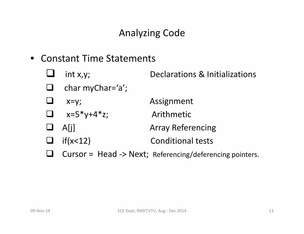
• Constant Time Statements int x,y; Declarations & Initializations char myChar=‘a’; x=y; Assignment x=5*y+4*z; Arithmetic A[j] Array Referencing if(x<12) Conditional tests Cursor = Head -> Next; Referencing/deferencing pointers.
• Constant Time Statements int x,y; Declarations & Initializations char myChar=‘a’; x=y; Assignment x=5*y+4*z; Arithmetic A[j] Array Referencing if(x<12) Conditional tests Cursor = Head -> Next; Referencing/deferencing pointers.
09-Nov-14 13ECE Dept, RNSIT,VTU, Aug - Dec 2014

Looping Constants
• For Loops, While Loops• Determine number of iterations and number of steps
per iteration.int sum=0; 1for (int j=0;j<N;j++) 3*N
sum=sum+j; 1*NTotal time for loop = 4 steps=O(1) steps per iteration.Total time is N.O(1)= O(N.1)=O(N) complexity of theloop is a constant.
• For Loops, While Loops• Determine number of iterations and number of steps
per iteration.int sum=0; 1for (int j=0;j<N;j++) 3*N
sum=sum+j; 1*NTotal time for loop = 4 steps=O(1) steps per iteration.Total time is N.O(1)= O(N.1)=O(N) complexity of theloop is a constant.
09-Nov-14 14ECE Dept, RNSIT,VTU, Aug - Dec 2014

While Loopbool done=false;int result=1;int n;While(!done){
result=result*n; ----1(multiply)+1(assignment)n-; -----1(decrement)if(n<=1)done=true;
}Total time is N.O(1)=O(N)
bool done=false;int result=1;int n;While(!done){
result=result*n; ----1(multiply)+1(assignment)n-; -----1(decrement)if(n<=1)done=true;
}Total time is N.O(1)=O(N)
09-Nov-14 15ECE Dept, RNSIT,VTU, Aug - Dec 2014

Sequences of Statements
int j,k,sum=0;for (j=0;j<N;j++)
for(k=0;K<j;k++)sum=sum+k*j;
for(i=0;i<N;i++)sum=sum+i;
The complexity is given byTotal time is N3+N=O(N3)
int j,k,sum=0;for (j=0;j<N;j++)
for(k=0;K<j;k++)sum=sum+k*j;
for(i=0;i<N;i++)sum=sum+i;
The complexity is given byTotal time is N3+N=O(N3)
09-Nov-14 16ECE Dept, RNSIT,VTU, Aug - Dec 2014

Conditional Statements
if(condition){statement1; ----- O(n2)elsestatement2; ----- O(n)
}Consider worst case complexity/maximum running time.
if(condition){statement1; ----- O(n2)elsestatement2; ----- O(n)
}Consider worst case complexity/maximum running time.
09-Nov-14 17ECE Dept, RNSIT,VTU, Aug - Dec 2014

Function Calls
• Cost = the call+ passing the arguments+ executing
the function/=returning a value.
• Making and returning from call – O(1)
• Passing arguments – depends on how it is passed –
passed by value/reference
• Cost of execution – body of function
• Determining cost of return – values returned
• Cost = the call+ passing the arguments+ executing
the function/=returning a value.
• Making and returning from call – O(1)
• Passing arguments – depends on how it is passed –
passed by value/reference
• Cost of execution – body of function
• Determining cost of return – values returned
09-Nov-14 18ECE Dept, RNSIT,VTU, Aug - Dec 2014

Analyzing Algorithms
• Complexity Function for• Analyzing Search AlgorithmsLinear Search – O(N)Binary Search – O(log2N)
• Analyzing Sort Algorithms Selection Sort – O(N2) Quick Sort - O(Nlog2N)
• Complexity Function for• Analyzing Search AlgorithmsLinear Search – O(N)Binary Search – O(log2N)
• Analyzing Sort Algorithms Selection Sort – O(N2) Quick Sort - O(Nlog2N)
09-Nov-14 19ECE Dept, RNSIT,VTU, Aug - Dec 2014
Analyzing Data Structures
• Insert/delete at the beginning• Insert/delete at the end• Insert/delete in the middle• Access at the beginning, the end and in the
middle.• Each has a complexity function of O(N)ArrayLinked List
• Insert/delete at the beginning• Insert/delete at the end• Insert/delete in the middle• Access at the beginning, the end and in the
middle.• Each has a complexity function of O(N)ArrayLinked List
09-Nov-14 20ECE Dept, RNSIT,VTU, Aug - Dec 2014

Instructions in Detail• Addressing Mode• Flow of control – Sequential
BranchLoopFunction Call
• Analyzing the flow of control – Assembly and C language• Example
ld r0,#0AAh --- 400nspush r0 ---600nsadd r0,r1 ----400ns
• Addressing Mode• Flow of control – Sequential
BranchLoopFunction Call
• Analyzing the flow of control – Assembly and C language• Example
ld r0,#0AAh --- 400nspush r0 ---600nsadd r0,r1 ----400ns
09-Nov-14 21ECE Dept, RNSIT,VTU, Aug - Dec 2014
Co-routine• A co-routine is a special kind of procedure call in
which there is a mutual call exchange betweencooperating procedures – 2 procedures sharing time.
• Similar to procedure and time budget.• Procedures execute till the end whereas co-routine
exit and return throughout the body of theprocedure.
• The control procedure starts the process. Eachcontext switch is determined by any of the of thefollowing – Control procedure, External event – atiming signal, internal event – a data value.
• A co-routine is a special kind of procedure call inwhich there is a mutual call exchange betweencooperating procedures – 2 procedures sharing time.
• Similar to procedure and time budget.• Procedures execute till the end whereas co-routine
exit and return throughout the body of theprocedure.
• The control procedure starts the process. Eachcontext switch is determined by any of the of thefollowing – Control procedure, External event – atiming signal, internal event – a data value.
09-Nov-14 22ECE Dept, RNSIT,VTU, Aug - Dec 2014

• The process continues until both procedures arecompleted.
• It is time burdened and for faster responsepreemption must be used.
Control Procedure
Procedure2 Procedure3
09-Nov-14 23ECE Dept, RNSIT,VTU, Aug - Dec 2014

Interrupt call
InterruptHandler
ForegroundTask
ISRForegroundTask
09-Nov-14 24ECE Dept, RNSIT,VTU, Aug - Dec 2014

Time Metrics• Response Time• Execution time• Throughput• Time loading – percentage of time that CPU is
doing useful work.• Memory loading – percentage of usable
memory.
• Response Time• Execution time• Throughput• Time loading – percentage of time that CPU is
doing useful work.• Memory loading – percentage of usable
memory.
09-Nov-14 25ECE Dept, RNSIT,VTU, Aug - Dec 2014

Response Time• Time interval between the event and completion of
associated action• Ex – A/D command and acquisition• Polled Loops – The response time consists of 3
componentsHardware delays in external device to set the
signaling event Time to test the flagTime needed to respond to and process the
event associated with the flag.
• Time interval between the event and completion ofassociated action
• Ex – A/D command and acquisition• Polled Loops – The response time consists of 3
componentsHardware delays in external device to set the
signaling event Time to test the flagTime needed to respond to and process the
event associated with the flag.
09-Nov-14 26ECE Dept, RNSIT,VTU, Aug - Dec 2014

External Hardware Device Delay
• Two Cases considereda) Case 1 - The response through external system to
prior internal eventb) Case 2- An asynchronous external event
Internal Event
Casual System RespondingSystem
Internal Event
Response from External system
Delay throughExternal System
09-Nov-14 27ECE Dept, RNSIT,VTU, Aug - Dec 2014

• Time to get the polling loop from the internal causal event• The delay through an external device• The time to generate the response• Flag time - Determined from the execution time of the
machine's bit test instruction• Processing time – time to perform the task associated with
triggering event
• Time to get the polling loop from the internal causal event• The delay through an external device• The time to generate the response• Flag time - Determined from the execution time of the
machine's bit test instruction• Processing time – time to perform the task associated with
triggering event
09-Nov-14 28ECE Dept, RNSIT,VTU, Aug - Dec 2014

Case 2 Asynchronous Event from External Device
• The occurrence of event cannot be determined.
09-Nov-14 29ECE Dept, RNSIT,VTU, Aug - Dec 2014

Co-routine
• Interrupt Driven Environment• Preemptive Schedule• Non-preemptive Schedule
09-Nov-14 30ECE Dept, RNSIT,VTU, Aug - Dec 2014

Interrupt Driven Environment
• Context switch to interrupt handler
• To acknowledge the interrupt
• Context switch to processing routine Context switch
back to original routine
• Context switch to interrupt handler
• To acknowledge the interrupt
• Context switch to processing routine Context switch
back to original routine
09-Nov-14 31ECE Dept, RNSIT,VTU, Aug - Dec 2014

Preemptive Schedule• Context Switch• Task Execution• Interrupt latency – Highest Priority
Lowest PriorityCase 1 Highest Priority – 3 Factors• The time from the leading edge of the interrupt in the
external device until that edge is recognized inside thesystem.
• The time to complete the current instruction if interrupts areenabled. Most processors complete the current instructionbefore switching context. Some permit an interrupt to berecognized at the micro instruction level. Thus the time isgoing to be bounded by the longest instruction.
• The time to complete the current task if interrupts aredisabled. This time will be bounded by the task size.
• Context Switch• Task Execution• Interrupt latency – Highest Priority
Lowest PriorityCase 1 Highest Priority – 3 Factors• The time from the leading edge of the interrupt in the
external device until that edge is recognized inside thesystem.
• The time to complete the current instruction if interrupts areenabled. Most processors complete the current instructionbefore switching context. Some permit an interrupt to berecognized at the micro instruction level. Thus the time isgoing to be bounded by the longest instruction.
• The time to complete the current task if interrupts aredisabled. This time will be bounded by the task size.
09-Nov-14 32ECE Dept, RNSIT,VTU, Aug - Dec 2014

Case 2 Low Priority Task
• 2 Cases First, the interrupt occurs and is processed. Second, the interrupt occurs and is interrupted. Unless
interrupts are disabled, the situation is non-deterministic. In critical cases, one may have to changethe priority or place limits on the number ofpreemptions.
• Non-Preemptive Schedule Since preemption is not allowed, times are computed as
in highest priority case.
09-Nov-14 33ECE Dept, RNSIT,VTU, Aug - Dec 2014

Time Loading
• Is percentage of time that the CPU is doing usefulwork – execution of tasks assigned to embeddedsystem
• The time loading is measured in terms of executiontimes of primary and secondary(supported) tasks.
• Time loading = primary/primary+secondary• To compute the time, 3 methods are used
Instruction countingSimulationPhysical measurement
09-Nov-14 34ECE Dept, RNSIT,VTU, Aug - Dec 2014

Instruction Counting
• For periodic systems, the total execution time iscomputed and then divided by time for the individualmodule
• For sporadic systems, the maximum task executionrates are used, and the percentages are combinedover all of the tasks.
• Effective instruction counting requires understandingof basic flow of control through a piece of software.Altering the flow involves context switch
09-Nov-14 35ECE Dept, RNSIT,VTU, Aug - Dec 2014
Simulation• Complete understanding of the system and accurate
workload, accurate model of system• Model can include hardware or software or both• Tools like Verilog or VHDL is used for hardware
modeling• System C or a variety of software languages can be
used for software modeling
• Complete understanding of the system and accurateworkload, accurate model of system
• Model can include hardware or software or both• Tools like Verilog or VHDL is used for hardware
modeling• System C or a variety of software languages can be
used for software modeling
09-Nov-14 36ECE Dept, RNSIT,VTU, Aug - Dec 2014

Model• 2 major categories of models are behavior or conceptual and
structural or analytic• Behavioral – symbols for qualitative aspects• Structural – mathematical or logical relations to represent the
behavior System-level model Functional model Physical model Structural model Behavioral model Data model
• 2 major categories of models are behavior or conceptual andstructural or analytic
• Behavioral – symbols for qualitative aspects• Structural – mathematical or logical relations to represent the
behavior System-level model Functional model Physical model Structural model Behavioral model Data model
09-Nov-14 37ECE Dept, RNSIT,VTU, Aug - Dec 2014

Timers
• Timers can be associated with various busesor pieces of code in the system
• Start timer at beginning of the code and endtimer at end of code
• For determining the timing of blocks
• Timers can be associated with various busesor pieces of code in the system
• Start timer at beginning of the code and endtimer at end of code
• For determining the timing of blocks
09-Nov-14 38ECE Dept, RNSIT,VTU, Aug - Dec 2014

Instrumentation
• Numerous instruments – logic analyzer, codeanalyzer
• Maximum and minimum times, time loops, identifynon executed code, capture the rates of execution,frequently used code
• Limitation – there are like input to the system, notgood for typical and boundary conditions
• They are not predictive – don’t guaranteeperformance under all circumstance
• Provide significant information
09-Nov-14 39ECE Dept, RNSIT,VTU, Aug - Dec 2014

Memory Loading
• Most devices come with largememory
• But amount of memory may bereduced to save weight(aircraft/spacecraft)
• Memory loading is defined aspercentage of usable memory fora application
• Memory map – useful inunderstanding the allocation anduse of available memory
Memorymapped I/O
and DMA
Firmware
• Most devices come with largememory
• But amount of memory may bereduced to save weight(aircraft/spacecraft)
• Memory loading is defined aspercentage of usable memory fora application
• Memory map – useful inunderstanding the allocation anduse of available memory
RAM
Stack Space
SystemMemory
A Memory Map09-Nov-14 40ECE Dept, RNSIT,VTU, Aug - Dec 2014

• The total memory loading will be sum of individualloadings for instructions, stack and RAM
• The values of Mi reflect memory loading for eachportion of memory
• Pi represent the percentage of total memoryallocated for program
• MT is represented as percentage• Memory mapped I/O and DMA are not included in
the calculation, these are fixed by hardware design
09-Nov-14 41ECE Dept, RNSIT,VTU, Aug - Dec 2014

Example
• Let the system be implemented as followsMi=15Mb;MR=100Kb;MS=150KbPT=55%;PR=33%;PS=10%Find value of MT
09-Nov-14 42ECE Dept, RNSIT,VTU, Aug - Dec 2014

Designing a Memory Map
• Allocate minimum amount of memory necessary forthe instructions and the stack
• The firmware contains the program that implementsthe application
• Memory loading is computed by dividing the numberof user locations by the maximum allowable
• Ram area – global variables, registers• Ram improves the instruction fetch speed• Size of Ram area is decided at design time
09-Nov-14 43ECE Dept, RNSIT,VTU, Aug - Dec 2014

Stack Area
• Stores context information and auto variables• Multiple stacks depending on design• Capacity – design time• Maximum stack size can be computed using• US=Smax*Tmax
• Memory loading
• Stores context information and auto variables• Multiple stacks depending on design• Capacity – design time• Maximum stack size can be computed using• US=Smax*Tmax
• Memory loading
09-Nov-14 44ECE Dept, RNSIT,VTU, Aug - Dec 2014

Evaluating Performance• Depends on information• Exact times if computable• Measurement technique
Criterion Analyticmethod
Simulation Measurement
Stage Any Any Post prototype
Time Required Small Medium VariesTime Required Small Medium Varies
Tools Analysis Computer languages Instrumentation
Accuracy Low Moderate Varies
Trade-off Evaluation Easy Moderate Difficult
Cost Small Medium High
Scalability Low Medium High
09-Nov-14 45ECE Dept, RNSIT,VTU, Aug - Dec 2014
Early Stages• The model should be hierarchical. Complex system
can be modeled by decomposing it to simpler parts.Progressive refinement, abstraction, reuse of existingcomponents
• The model should express concurrent and temporalinterdependencies among physical and modeledelements. Understand dynamic performance andinteraction between other elements
• Model should be graphical; not necessary• Permit worst case and scenario analysis, boundary
condition
• The model should be hierarchical. Complex systemcan be modeled by decomposing it to simpler parts.Progressive refinement, abstraction, reuse of existingcomponents
• The model should express concurrent and temporalinterdependencies among physical and modeledelements. Understand dynamic performance andinteraction between other elements
• Model should be graphical; not necessary• Permit worst case and scenario analysis, boundary
condition
09-Nov-14 46ECE Dept, RNSIT,VTU, Aug - Dec 2014

Mid Stages
• Real components of design• Prototype modules and integrate them into
subsystems
Later Stages• Integrate into larger system
• Real components of design• Prototype modules and integrate them into
subsystems
Later Stages• Integrate into larger system
09-Nov-14 47ECE Dept, RNSIT,VTU, Aug - Dec 2014

Performance Optimization
• What is being optimized ?
• Why is it being optimized?
• What is the effect on overall system?
• Is optimization appropriate operating context?
• What is being optimized ?
• Why is it being optimized?
• What is the effect on overall system?
• Is optimization appropriate operating context?
09-Nov-14 48ECE Dept, RNSIT,VTU, Aug - Dec 2014

Common Mistakes
• Expecting improvement in one aspect of the design
to improve overall performance proportional to
improvement
• Using hardware independent metrics to predict
performance
• Using peak performance
• Comparing performance based on couple of metrics
• Using synthetic benchmarks
• Expecting improvement in one aspect of the design
to improve overall performance proportional to
improvement
• Using hardware independent metrics to predict
performance
• Using peak performance
• Comparing performance based on couple of metrics
• Using synthetic benchmarks
09-Nov-14 49ECE Dept, RNSIT,VTU, Aug - Dec 2014

Tricks of the Trade
Response times and time loading can be reduced innumber of ways1. Perform measurements and computations at a rate
of change and values of the data, type of data,number of significant digits and operations
2. Use of look up tables or combinational logic3. Modification of certain operations to reduce certain
parameters4. Learn from compiler experts5. Loop management6. Flow of control optimization
09-Nov-14 50ECE Dept, RNSIT,VTU, Aug - Dec 2014

7. Use registers and caches8. Use of only necessary values9. Optimize a common path of frequently used
code block10.Use page mode accesses11.Know when to use recursion vs. iteration12.Macros and Inlining functions
Tricks of the Trade
7. Use registers and caches8. Use of only necessary values9. Optimize a common path of frequently used
code block10.Use page mode accesses11.Know when to use recursion vs. iteration12.Macros and Inlining functions
09-Nov-14 51ECE Dept, RNSIT,VTU, Aug - Dec 2014

Hardware Accelerators• One technique to improve the performance of software
implementation is to move some functionality to hardware• Such a collection of components is called hardware
accelerators• Often attached to CPU bus• Communication with CPU is accomplished by – shared
variables, shared memory• An accelerator is distinguished from coprocessor• The accelerator does not execute instructions; its interface
appears as I/O• Designed to perform a specific operation and is generally
implemented as an ASIC,FPGA, CPLD
• One technique to improve the performance of softwareimplementation is to move some functionality to hardware
• Such a collection of components is called hardwareaccelerators
• Often attached to CPU bus• Communication with CPU is accomplished by – shared
variables, shared memory• An accelerator is distinguished from coprocessor• The accelerator does not execute instructions; its interface
appears as I/O• Designed to perform a specific operation and is generally
implemented as an ASIC,FPGA, CPLD
09-Nov-14 52ECE Dept, RNSIT,VTU, Aug - Dec 2014

• Hardware accelerators are used when there arefunctions whose operations do not map onto theCPU
• Examples – bit and bit field operations, differingprecisions, high speed arithmetic, FFT calculations,high speed/demand input output operations,streaming applications
Hardware Accelerators
• Hardware accelerators are used when there arefunctions whose operations do not map onto theCPU
• Examples – bit and bit field operations, differingprecisions, high speed arithmetic, FFT calculations,high speed/demand input output operations,streaming applications
09-Nov-14 53ECE Dept, RNSIT,VTU, Aug - Dec 2014

Optimizing for Power Consumption
• Safe mode, low power mode, sleep mode• Advanced Configuration and power interface (ACPI)
is international standardSoftwareHardware
•SoftwareThe algorithms usedLocation of codeUse of software to control various subsystems
• Safe mode, low power mode, sleep mode• Advanced Configuration and power interface (ACPI)
is international standardSoftwareHardware
•SoftwareThe algorithms usedLocation of codeUse of software to control various subsystems
09-Nov-14 54ECE Dept, RNSIT,VTU, Aug - Dec 2014

Techniques to measure power consumption
• Identify the portion of the code to be analyzed• Measure the current power consumed by processor while
code is being executed• Modify the loop, such that code comprising the loop is
disabled. Ensure compiler has not optimized the loop orsection of code out
• Measure current power consumed by processor• Kind the instructions• Collection or sequence of instructions executed• Locations of the instructions and their operands
09-Nov-14 55ECE Dept, RNSIT,VTU, Aug - Dec 2014

09-Nov-14 56ECE Dept, RNSIT,VTU, Aug - Dec 2014

Relative Power consumption for Common ProcessorOperation
Operation Relative PowerConsumption
16-Bit Add 1
16-Bit Multiply 3.6
8x128x16SRAM Read
4.4
8x128x16SRAM Write
98x128x16SRAM Write
9
I/O access 10
16-bit DRAMMemorytransfer
33
Using cache have significant effect on system power consumption, SRAM consumesmore power than DRAM on per-cell basis and cache is generally SRAM. The size ofcache should be optimized.
09-Nov-14 57ECE Dept, RNSIT,VTU, Aug - Dec 2014

Other Techniques
• Power aware compilers• Use of registers effectively• Look for Cache conflicts and eliminate if
possible• Unroll loops• Eliminate recursive procedures
• Power aware compilers• Use of registers effectively• Look for Cache conflicts and eliminate if
possible• Unroll loops• Eliminate recursive procedures
09-Nov-14 58ECE Dept, RNSIT,VTU, Aug - Dec 2014

Hardware Power Optimization Techniques
Power Management Schemes• Best option to turn off system when not in use- power
consumption is limited to leakage-lower bound ofconsumption- static power
• Upper bound – apply power to all parts of the system –maximum value – dynamic power
• The goal is to find a mid power consumption value, governedby specs
• ex – topographic mapping satellite• Approaches
Decide which portion of system to power downDecide components which have to shut down instantlyRecognize which components do not power up instantly
09-Nov-14 59ECE Dept, RNSIT,VTU, Aug - Dec 2014

Basic for System power down-power up sequence
09-Nov-14 60ECE Dept, RNSIT,VTU, Aug - Dec 2014

Predictive Shutdown• The approaches discussed in previous slide is not possible
everywhere.• Knowledge of current status and previous state must be
considered to shutdown the system – predictive shutdown• Such a technique is used in branch prediction logic in
instruction prefetch pipeline• This can lead to premature shutdown or restart
Timers• Another technique is to use timers• Timers monitor the system behavior and turn off when timer
expires• Device turns on again based on demand
• The approaches discussed in previous slide is not possibleeverywhere.
• Knowledge of current status and previous state must beconsidered to shutdown the system – predictive shutdown
• Such a technique is used in branch prediction logic ininstruction prefetch pipeline
• This can lead to premature shutdown or restart
Timers• Another technique is to use timers• Timers monitor the system behavior and turn off when timer
expires• Device turns on again based on demand
09-Nov-14 61ECE Dept, RNSIT,VTU, Aug - Dec 2014

Producer, service, consumer• Based on queuing theory• Producer is the system which is to be powered on• Consumer is part of a system which needs a service• A power manager monitors behavior of system and utilizes a
schedule based on Markov modeling which maximizes systemcomputational performance satisfying power budget
• Based on queuing theory• Producer is the system which is to be powered on• Consumer is part of a system which needs a service• A power manager monitors behavior of system and utilizes a
schedule based on Markov modeling which maximizes systemcomputational performance satisfying power budget
09-Nov-14 62ECE Dept, RNSIT,VTU, Aug - Dec 2014
Example• The operating system is responsible for dynamically
controlling the power in a simple I/O subsystems• The dynamically controlled portion supports two modes – OFF
and ON• The dynamic subcomponents consume 10watts when on and
0 watts when off• Switching takes 2 seconds and consumes 40joules to switch
from off state to on state and one second and 10joules toswitch from on to off
• The request has a period of 25 seconds• Graphically 3 alternate schemes as illustrated• Observe same average throughput with substantially reduced
power consumption
• The operating system is responsible for dynamicallycontrolling the power in a simple I/O subsystems
• The dynamically controlled portion supports two modes – OFFand ON
• The dynamic subcomponents consume 10watts when on and0 watts when off
• Switching takes 2 seconds and consumes 40joules to switchfrom off state to on state and one second and 10joules toswitch from on to off
• The request has a period of 25 seconds• Graphically 3 alternate schemes as illustrated• Observe same average throughput with substantially reduced
power consumption
09-Nov-14 63ECE Dept, RNSIT,VTU, Aug - Dec 2014

Example
09-Nov-14 64ECE Dept, RNSIT,VTU, Aug - Dec 2014

Advanced Configuration and Power interface (ACPI)
• ACPI is an industry standard power management scheme thatwas initially applied to PC specifically Windows.
• This standard provides some basic power managementfacilities as well as interfaces to the hardware
• The software more specifically operating systems providesmanagement module
• It is responsibility of OS to specify the power managementpolicy for the system
• The OS uses ACPI module to send the required controls tohardware and to monitor the state of hardware as an input topower manager
• The behavior of the ACPI scheme is expressed in the statediagram
09-Nov-14 65ECE Dept, RNSIT,VTU, Aug - Dec 2014

ACPI
09-Nov-14 66ECE Dept, RNSIT,VTU, Aug - Dec 2014

• The standard supports 5 global power states1. G3- hard off or full off – defined as physically off
state – system consumes no power2. G2- soft off requires full OS reboot to restore
system to full operational condition3. G1- sleeping state – the system appears to be off.
The time required to return to an operationalcondition is inversely proportional to powerconsumption
4. G0 – working state in which the system is fullyusable
5. Legacy state – the system doesnot comply with ACPI
09-Nov-14 67ECE Dept, RNSIT,VTU, Aug - Dec 2014
• Substates1. S1- low wakeup latency – ensures no loss of
system context2. S2- low wakeup latency state – has loss of
CPU and system cache state3. S3- low wakeup latency state – all system
state except for main memory is lost4. S4- lowest power sleeping state – all the
devices are off
• Substates1. S1- low wakeup latency – ensures no loss of
system context2. S2- low wakeup latency state – has loss of
CPU and system cache state3. S3- low wakeup latency state – all system
state except for main memory is lost4. S4- lowest power sleeping state – all the
devices are off
09-Nov-14 68ECE Dept, RNSIT,VTU, Aug - Dec 2014
Caches and Performance• Based on locality of reference characteristics, small amounts
of high speed memory to hold a subset of instructions anddata for immediate use can be used
• Such a scheme gives the illusion that the program hasunlimited amounts of high speed memory
• The bulk of instructions and data are held in memory withmuch longer cycle/access times than available in the systemCPU
• One major problem in real time embedded application is thatcache behavior is non deterministic
• It is difficult to predict when there will be a cache hit or miss• It is difficult to set reasonable upper bounds on execution
times for tasks
• Based on locality of reference characteristics, small amountsof high speed memory to hold a subset of instructions anddata for immediate use can be used
• Such a scheme gives the illusion that the program hasunlimited amounts of high speed memory
• The bulk of instructions and data are held in memory withmuch longer cycle/access times than available in the systemCPU
• One major problem in real time embedded application is thatcache behavior is non deterministic
• It is difficult to predict when there will be a cache hit or miss• It is difficult to set reasonable upper bounds on execution
times for tasks
09-Nov-14 69ECE Dept, RNSIT,VTU, Aug - Dec 2014

• The problem is due to 2 sources – conditional branches andshared access with preemption
• Conditional branches are handled with good branchprediction algorithms, but cannot be solved completely
• The path taken and a successful cache access may vary withiteration
• This is overcome with pipelined architectures• Pipelining techniques are used to prefetch data and
instructions while other activities are taking place• The selection of an alternate branch requires that the pipe be
flushed and refilled• This may lead to cache miss and time delay
Pipelining
• The problem is due to 2 sources – conditional branches andshared access with preemption
• Conditional branches are handled with good branchprediction algorithms, but cannot be solved completely
• The path taken and a successful cache access may vary withiteration
• This is overcome with pipelined architectures• Pipelining techniques are used to prefetch data and
instructions while other activities are taking place• The selection of an alternate branch requires that the pipe be
flushed and refilled• This may lead to cache miss and time delay
09-Nov-14 70ECE Dept, RNSIT,VTU, Aug - Dec 2014

Preemption and multi tasking
• In a multi tasking interrupt context, one task maypreempt the other
• This requires different block of data/instructions thatwill have significant number of cache misses as taskswitch
• Similar situation arises during Von Neuman machine– same memory for code and data
• In a multi tasking interrupt context, one task maypreempt the other
• This requires different block of data/instructions thatwill have significant number of cache misses as taskswitch
• Similar situation arises during Von Neuman machine– same memory for code and data
09-Nov-14 71ECE Dept, RNSIT,VTU, Aug - Dec 2014

Shared Access• Example – consider a direct mapping caching scheme• If 1K cache with blocks of 64 words, such blocks from main
memory addresses 0,1024,2048 and so on• Assume a following memory map• Instructions are loaded starting at location 1024, and data is
loaded starting at location 8192. consider the simple codefragment
for(i=0;i<10:i++){
a[i]= b[i]+4;}
• Example – consider a direct mapping caching scheme• If 1K cache with blocks of 64 words, such blocks from main
memory addresses 0,1024,2048 and so on• Assume a following memory map• Instructions are loaded starting at location 1024, and data is
loaded starting at location 8192. consider the simple codefragment
for(i=0;i<10:i++){
a[i]= b[i]+4;}
09-Nov-14 72ECE Dept, RNSIT,VTU, Aug - Dec 2014

• On the first access, the instruction access will missand bring in the appropriate block from mainmemory
• The instruction will execute and have to bring in data• The data access will miss and bring in the
appropriate block from main memory• Because block 0 is occupied, the data block will
overwrite the instructions in cache block 0• On second access, the instruction access will again
miss and bring in the appropriate block from themain memory
• The miss occurs because the instructions had beenover written by the incoming data
09-Nov-14 73ECE Dept, RNSIT,VTU, Aug - Dec 2014

• The instruction will execute and have to bring thedata again. Because block 0 is again occupied, thedata block will over write block 0 again
• This process repeats causing serious degradation• There is also a time burden of searching and
managing the cache• The continuing main memory accesses can also
increase the power consumption of the system
09-Nov-14 74ECE Dept, RNSIT,VTU, Aug - Dec 2014

Possible solutions
1. Use a set associative rather than direct
mapping scheme
2. Move to Harvard or Aiken Architecture
3. Support an instruction cache and data cache
1. Use a set associative rather than direct
mapping scheme
2. Move to Harvard or Aiken Architecture
3. Support an instruction cache and data cache
09-Nov-14 75ECE Dept, RNSIT,VTU, Aug - Dec 2014

Smart Memory Allocation for Real time (SMART)
• Cache is decomposed into restricted regions andcommon portions
• A critical task is assigned a restricted portion on startup
• All cache accesses are restricted to those partitionsand to common area
• The task retains exclusive rights to such areas untilterminated or aborted
• This remains an open problem and various heuristicschemes have been explored and utilized
09-Nov-14 76ECE Dept, RNSIT,VTU, Aug - Dec 2014