Embed Size (px)
Citation preview

Deepak Bhalla (Asst. Professor (MCA & IT Dept.)) Deepak Bhalla (Asst. Professor (MCA & IT Dept.))
Unit-3
Control Unit Organization
MY
csvtu
Note
s
ww
w.m
ycsvtu
no
tes.in

Deepak Bhalla (Asst. Professor (MCA & IT Dept.))
Control Unit • All the control unit does is generate a set of control
signals
• Each control signal is on or off
• Represent each control signal by a bit
• Have a control word for each micro-operation
• While doing instruction fetch, the instruction consisted of state information and in each state the signals that are necessary to setup the data path that information is available from the micro word
MY
csvtu
Note
s
ww
w.m
ycsvtu
no
tes.in

Deepak Bhalla (Asst. Professor (MCA & IT Dept.))
• Have a sequence of control words for each machine code instruction
• Add an address to specify the next micro-instruction, depending on conditions.
• A control unit undertakes the following responsibilities:
•Instruction Interpretation
•Instruction Sequencing
MY
csvtu
Note
s
ww
w.m
ycsvtu
no
tes.in

Deepak Bhalla (Asst. Professor (MCA & IT Dept.))
Instruction Interpretation • In the interpretation phase, the control unit reads instructions from the
memory, using the PC as a pointer.
• Then it identifies the instruction type, obtains the necessary operands, and routes them to the appropriate functional units of the execution unit.
• Then the necessary signals are issued to the execution unit to perform the desired operation, and the results are routed to the specified destination.
MY
csvtu
Note
s
ww
w.m
ycsvtu
no
tes.in

Deepak Bhalla (Asst. Professor (MCA & IT Dept.))
Instruction Sequencing
• In the sequencing phase, the control unit decides the address of the next instruction to be executed and loads it into the PC. M
Ycsvtu
Note
s
ww
w.m
ycsvtu
no
tes.in
Deepak Bhalla (Asst. Professor (MCA & IT Dept.))
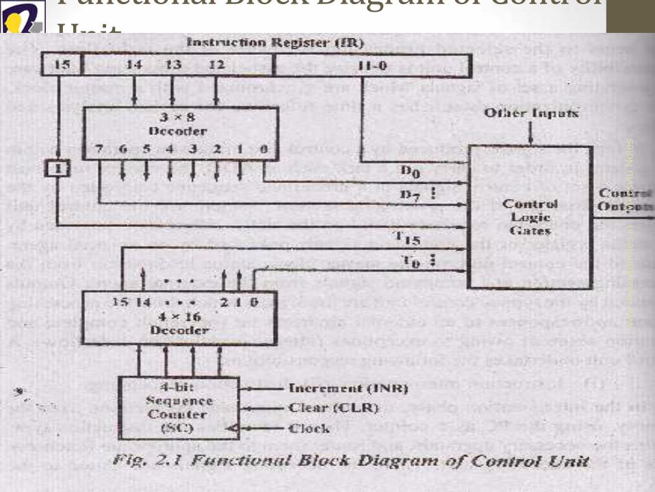
Functional Block Diagram of Control Unit
MY
csvtu
Note
s
ww
w.m
ycsvtu
no
tes.in

Deepak Bhalla (Asst. Professor (MCA & IT Dept.))
• Figure above shows the functional block diagram of the control unit.
• It consists of two decoders-a sequence counter and a number of control logic gates.
• An instruction read from the memory is kept in the instruction register (IR).
• The instruction register as shown in the figure is divided into 3 parts.
• 1 bit
• The operation code
• And bits through 0 through 11
MY
csvtu
Note
s
ww
w.m
ycsvtu
no
tes.in
Deepak Bhalla (Asst. Professor (MCA & IT Dept.))
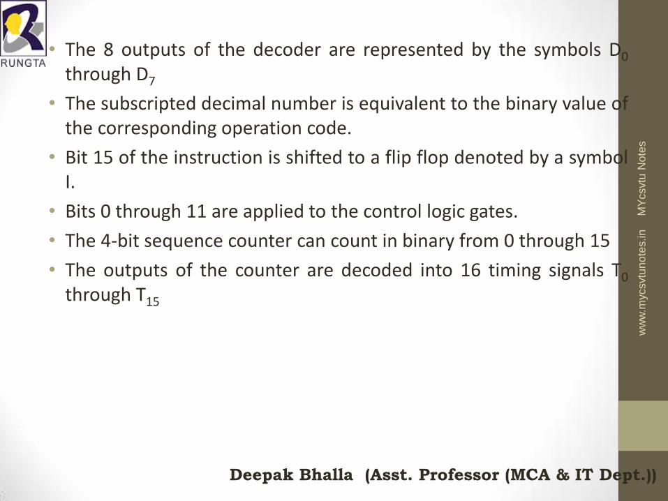
• The 8 outputs of the decoder are represented by the symbols D0 through D7
• The subscripted decimal number is equivalent to the binary value of the corresponding operation code.
• Bit 15 of the instruction is shifted to a flip flop denoted by a symbol I.
• Bits 0 through 11 are applied to the control logic gates.
• The 4-bit sequence counter can count in binary from 0 through 15
• The outputs of the counter are decoded into 16 timing signals T0 through T15
MY
csvtu
Note
s
ww
w.m
ycsvtu
no
tes.in
Deepak Bhalla (Asst. Professor (MCA & IT Dept.))
• Sequence counter (SC) can be incremented or cleared synchronously.
• Most of the time, the counter is incremented to provide the sequence of timing signals out of 4 x 16 decoder.
• Once in a while, the counter is cleared to 0, causing the next active timing signal to be T0 M
Ycsvtu
Note
s
ww
w.m
ycsvtu
no
tes.in
Deepak Bhalla (Asst. Professor (MCA & IT Dept.))
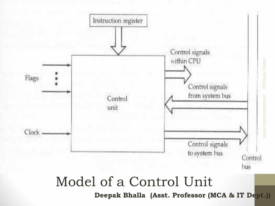
Model of a Control Unit
MY
csvtu
Note
s
ww
w.m
ycsvtu
no
tes.in

Deepak Bhalla (Asst. Professor (MCA & IT Dept.))
• Figure above is a general model of the control unit, showing all of its inputs and outputs.
• The inputs are as follows :
• Clock : This is how the control unit “keep time”. The control unit causes one micro operation to be performed for each clock pulse. This is sometimes referred to as the processor cycle time or the clock cycle time.
• Instruction Register : The opcode of the current instruction is used to determine which micro operations to perform during the execution cycle.
MY
csvtu
Note
s
ww
w.m
ycsvtu
no
tes.in

Deepak Bhalla (Asst. Professor (MCA & IT Dept.))
• Flags : These are needed by the control unit to determine the status of the processor and the outcome of the previous ALU operations.
• For example , for the increment -and –skip- if zero (ISZ) instruction , the control unit sill increment the PC if zero flag is set.
• Control Signals From Control Bus : The control bus portion of the system bus provides signal to the control unit, such as interrupt signals and acknowledgement.
MY
csvtu
Note
s
ww
w.m
ycsvtu
no
tes.in

Deepak Bhalla (Asst. Professor (MCA & IT Dept.))
MY
csvtu
Note
s
ww
w.m
ycsvtu
no
tes.in

Deepak Bhalla (Asst. Professor (MCA & IT Dept.))
MY
csvtu
Note
s
ww
w.m
ycsvtu
no
tes.in

Deepak Bhalla (Asst. Professor (MCA & IT Dept.))
Micro-Operations
• A computer executes a program
• Fetch/execute cycle
• Each cycle has a number of steps
• Called micro-operations
• Each step does very little
• Atomic operation of CPU
MY
csvtu
Note
s
ww
w.m
ycsvtu
no
tes.in

Deepak Bhalla (Asst. Professor (MCA & IT Dept.))
Constituent Elements of Program Execution
MY
csvtu
Note
s
ww
w.m
ycsvtu
no
tes.in

Deepak Bhalla (Asst. Professor (MCA & IT Dept.))
Fetch - 4 Registers • Memory Address Register (MAR)
• Connected to address bus
• Specifies address for read or write op
• Memory Buffer Register (MBR) • Connected to data bus
• Holds data to write or last data read
• Program Counter (PC) • Holds address of next instruction to be fetched
• Instruction Register (IR) • Holds last instruction fetched
MY
csvtu
Note
s
ww
w.m
ycsvtu
no
tes.in

Deepak Bhalla (Asst. Professor (MCA & IT Dept.))
Fetch Sequence
• Address of next instruction is in PC
• Address (MAR) is placed on address bus
• Control unit issues READ command
• Result (data from memory) appears on data bus
• Data from data bus copied into MBR
• PC incremented by 1 (in parallel with data fetch from memory)
• Data (instruction) moved from MBR to IR/IBR
• MBR is now free for further data fetches
MY
csvtu
Note
s
ww
w.m
ycsvtu
no
tes.in

Deepak Bhalla (Asst. Professor (MCA & IT Dept.))
Fetch Sequence (symbolic)
• t1: MAR <- (PC)
• t2: MBR <- (memory)
• PC <- (PC) +1
• t3: IR <- (MBR)
• (tx = time unit/clock cycle)
• or
• t1: MAR <- (PC)
• t2: MBR <- (memory)
• t3: PC <- (PC) +1
• IR <- (MBR)
MY
csvtu
Note
s
ww
w.m
ycsvtu
no
tes.in

Deepak Bhalla (Asst. Professor (MCA & IT Dept.))
Indirect Cycle
• MAR <- (IRaddress) - address field of IR
• MBR <- (memory)
• IRaddress <- (MBRaddress)
• MBR contains an address
• IR is now in same state as if direct addressing had been used
• (What does this say about IR size?)
MY
csvtu
Note
s
ww
w.m
ycsvtu
no
tes.in
Deepak Bhalla (Asst. Professor (MCA & IT Dept.))
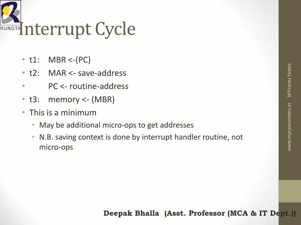
Interrupt Cycle
• t1: MBR <-(PC)
• t2: MAR <- save-address
• PC <- routine-address
• t3: memory <- (MBR)
• This is a minimum
• May be additional micro-ops to get addresses
• N.B. saving context is done by interrupt handler routine, not micro-ops
MY
csvtu
Note
s
ww
w.m
ycsvtu
no
tes.in

Deepak Bhalla (Asst. Professor (MCA & IT Dept.))
Execute Cycle (ADD)
• Different for each instruction
• e.g. ADD R1,X - add the contents of location X to Register 1 , result in R1
• t1: MAR <- (IRaddress)
• t2: MBR <- (memory)
• t3: R1 <- R1 + (MBR)
• Note no overlap of micro-operations
MY
csvtu
Note
s
ww
w.m
ycsvtu
no
tes.in

Deepak Bhalla (Asst. Professor (MCA & IT Dept.))
Execute Cycle (ISZ)
• ISZ X - increment and skip if zero
• t1: MAR <- (IRaddress)
• t2: MBR <- (memory)
• t3: MBR <- (MBR) + 1
• t4: memory <- (MBR)
• if (MBR) == 0 then PC <- (PC) + 1
• Notes:
• if is a single micro-operation
• Micro-operations done during t4
MY
csvtu
Note
s
ww
w.m
ycsvtu
no
tes.in

Deepak Bhalla (Asst. Professor (MCA & IT Dept.))
Functional Requirements
• Define basic elements of processor
• Describe micro-operations processor performs
• Determine functions control unit must perform
MY
csvtu
Note
s
ww
w.m
ycsvtu
no
tes.in

Deepak Bhalla (Asst. Professor (MCA & IT Dept.))
Types of Micro-operation
• Transfer data between registers
• Transfer data from register to external
• Transfer data from external to register
• Perform arithmetic or logical ops
MY
csvtu
Note
s
ww
w.m
ycsvtu
no
tes.in

Deepak Bhalla (Asst. Professor (MCA & IT Dept.))
Functions of Control Unit
• Sequencing
• Causing the CPU to step through a series of micro-operations in the proper sequence , based on the program being executed.
• Execution
• Control unit causes each micro operation to be performed.
• This is done using Control Signals
MY
csvtu
Note
s
ww
w.m
ycsvtu
no
tes.in

Deepak Bhalla (Asst. Professor (MCA & IT Dept.))
Control unit implementations • To execute instructions, a computer’s processor must generate the control
signals used to perform the processor's actions in the proper sequence.
• This sequence of actions can either be executed by another processor's software (for example in software emulation or simulation of a processor) or in hardware.
• Hardware methods fall into two categories: the processor's hardware signals are generated either by hardwired control, in which the instruction bits directly generate the signals, or by microprogrammed control in which a dedicated microcontroller executes a microprogram to generate the signals.
MY
csvtu
Note
s
ww
w.m
ycsvtu
no
tes.in
Deepak Bhalla (Asst. Professor (MCA & IT Dept.))
Hardware Control Unit
•When a control signals are generated by hardware using conventional logic design techniques, the control unit is said to be Hardwired.
•A diagram of hardwired control unit is shown in the figure below:
MY
csvtu
Note
s
ww
w.m
ycsvtu
no
tes.in

Deepak Bhalla (Asst. Professor (MCA & IT Dept.))
MY
csvtu
Note
s
ww
w.m
ycsvtu
no
tes.in

Deepak Bhalla (Asst. Professor (MCA & IT Dept.))
• In this case, the control unit is a combinatorial circuit; it gets a set of inputs (from IR, flags, clock, system bus) and transforms them into a set of control signals.
• This control unit may be based on the counter driven by a clock signal,CLK.
• The required control signals are uniquely determined by the following information :
i) Contents of the control counter.
ii) Contents of the instruction register
iii)Contents of the condition code and
other status flags.
By status flags, we mean the signals
representing the states of various
sections of the CPU and various control
lines connected to it.
MY
csvtu
Note
s
ww
w.m
ycsvtu
no
tes.in

Deepak Bhalla (Asst. Professor (MCA & IT Dept.))
• In order to gain some insight into the structure of the control unit, we will start by giving a simplified view of the hardware involved.
• The decoder encoder block in fig 2.3 is a combinational circuit which produces the required control outputs, depending on the state of all its input.
• By separating the decoding and encoding functions, we obtain the more detailed block diagram in figure below
MY
csvtu
Note
s
ww
w.m
ycsvtu
no
tes.in

Deepak Bhalla (Asst. Professor (MCA & IT Dept.))
MY
csvtu
Note
s
ww
w.m
ycsvtu
no
tes.in
Deepak Bhalla (Asst. Professor (MCA & IT Dept.))
Advantages of Hardwired Control • Hardwired Control is more advantageous as
compared to microprogram control.
• In hardware organization, the control logic is implemented with gates, flip-flops, decoders and other digital circuits
• Hardwired control provides highest speed.
• It can be optimized to produced a fast mode of operation.
• RISCs are implemented with hardwired control.
MY
csvtu
Note
s
ww
w.m
ycsvtu
no
tes.in

Deepak Bhalla (Asst. Professor (MCA & IT Dept.))
Problems With Hard Wired Designs •Complex sequencing & micro-
operation logic
•Difficult to design and test
• Inflexible design
•Difficult to add new instructions
MY
csvtu
Note
s
ww
w.m
ycsvtu
no
tes.in

Deepak Bhalla (Asst. Professor (MCA & IT Dept.))
Micro Programmed Control Unit • The idea of microprogramming was introduced by M. V.
Wilkes in 1951 as an intermediate level to execute computer program instructions.
• Microprograms were organized as a sequence of microinstructions and stored in special control memory.
• The algorithm for the microprogram control unit is usually specified by flow-chart description
MY
csvtu
Note
s
ww
w.m
ycsvtu
no
tes.in

Deepak Bhalla (Asst. Professor (MCA & IT Dept.))
• The main advantage of the microprogram control unit is the simplicity of its structure.
•Outputs of the controller are organized in microinstructions and they can be easily replaced
MY
csvtu
Note
s
ww
w.m
ycsvtu
no
tes.in

Deepak Bhalla (Asst. Professor (MCA & IT Dept.))
MY
csvtu
Note
s
ww
w.m
ycsvtu
no
tes.in

Deepak Bhalla (Asst. Professor (MCA & IT Dept.))
• The summary of the use of various components included in this organization is given below:
•Control Memory Buffer Register(CMBR) :
• Control means buffer register functions the same as the memory buffer register of the main memory.
• Basically it is a latch, and serves as a buffer from microinstructions retrieved from the control memory.
• Typically, each microinstructions will have three distinct fields.
MY
csvtu
Note
s
ww
w.m
ycsvtu
no
tes.in

Deepak Bhalla (Asst. Professor (MCA & IT Dept.))
Condition Select Branch Address Field
Control Function Field
The control select field chooses the external condition to be tested.
In case the select condition is true the output of the MUX will be 1, because the output of the multiplexer is connected to the load input of the micro program counter(MPC), the MPC will be loaded with the address specified in the branch address field of the micro instruction
MY
csvtu
Note
s
ww
w.m
ycsvtu
no
tes.in
Deepak Bhalla (Asst. Professor (MCA & IT Dept.))
• If the selected external condition is false, then microprogram counter will point to the next microinstruction to be executed.
• So this arrangement permits conditional branching.
• The control function field of the microinstruction may hold the control information in an encoded form.
MY
csvtu
Note
s
ww
w.m
ycsvtu
no
tes.in

Deepak Bhalla (Asst. Professor (MCA & IT Dept.))
Micro Program Counter
• The microprogram counter holds the address of the next microinstruction to be executed.
• Initially it is loaded from an external source to point to the starting address of the microprogram to be executed.
• From then on, the microprogram counter is incremented after each instruction fetch, and the instruction fetched is shifted to the CMBR.
MY
csvtu
Note
s
ww
w.m
ycsvtu
no
tes.in
Deepak Bhalla (Asst. Professor (MCA & IT Dept.))
• If a branch instruction is encountered , then the microprogram counter will be loaded with the contents of branch address field of the micro instruction that is held in the control memory buffer register.
MY
csvtu
Note
s
ww
w.m
ycsvtu
no
tes.in

Deepak Bhalla (Asst. Professor (MCA & IT Dept.))
External Condition Select MUX
• The MUX chooses one of the external condition according to the contents of the condition select field of the microinstruction.
• So, the condition to be chosen must be specified in an encoded form.
MY
csvtu
Note
s
ww
w.m
ycsvtu
no
tes.in
Deepak Bhalla (Asst. Professor (MCA & IT Dept.))
Difference Between Hardwired & Micro Programmed Control • Hardwired control is more advantageous as compared to microprogram
control.
• In the hardwire organization, the control logic is implemented with gates, flip-flop, decoders and other digital circuits.
• It has the advantage that it can be optimized to produce a fast mode of operation.
• Mostly computer based on the reduced instruction set computer (RISC) architecture concept use hardwired control, as the name implies, requires changing in the wiring among the various components, if the design has to be modified or changed.
MY
csvtu
Note
s
ww
w.m
ycsvtu
no
tes.in

Deepak Bhalla (Asst. Professor (MCA & IT Dept.))
• In the micro programmed organization, the control information is stored in control memory.
• The control memory is programmed to initiate the required sequence of micro operation.
• The main advantage of microprogrammed control unit is the fact that once the hardwired configuration is established. There should be no need for further hardware or wiring changes.
MY
csvtu
Note
s
ww
w.m
ycsvtu
no
tes.in
Deepak Bhalla (Asst. Professor (MCA & IT Dept.))
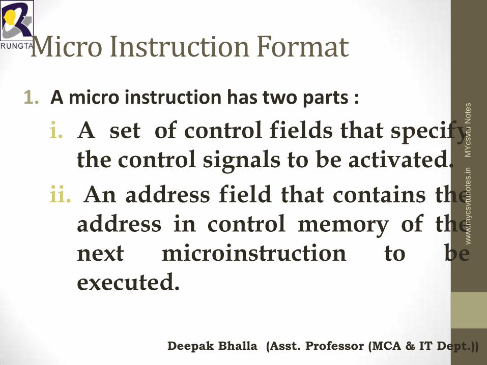
Micro Instruction Format
1. A micro instruction has two parts :
i. A set of control fields that specify the control signals to be activated.
ii. An address field that contains the address in control memory of the next microinstruction to be executed.
MY
csvtu
Note
s
ww
w.m
ycsvtu
no
tes.in

Deepak Bhalla (Asst. Professor (MCA & IT Dept.))
Microinstruction length is determined by 3 factors: • Maximum number of simultaneous micro
operations which must be specified , that is, the degree of parallelism required at the micro operation level.
• The manner in which control information is represented or encoded.
• The manner in which the next microinstruction is specified.
MY
csvtu
Note
s
ww
w.m
ycsvtu
no
tes.in
Deepak Bhalla (Asst. Professor (MCA & IT Dept.))
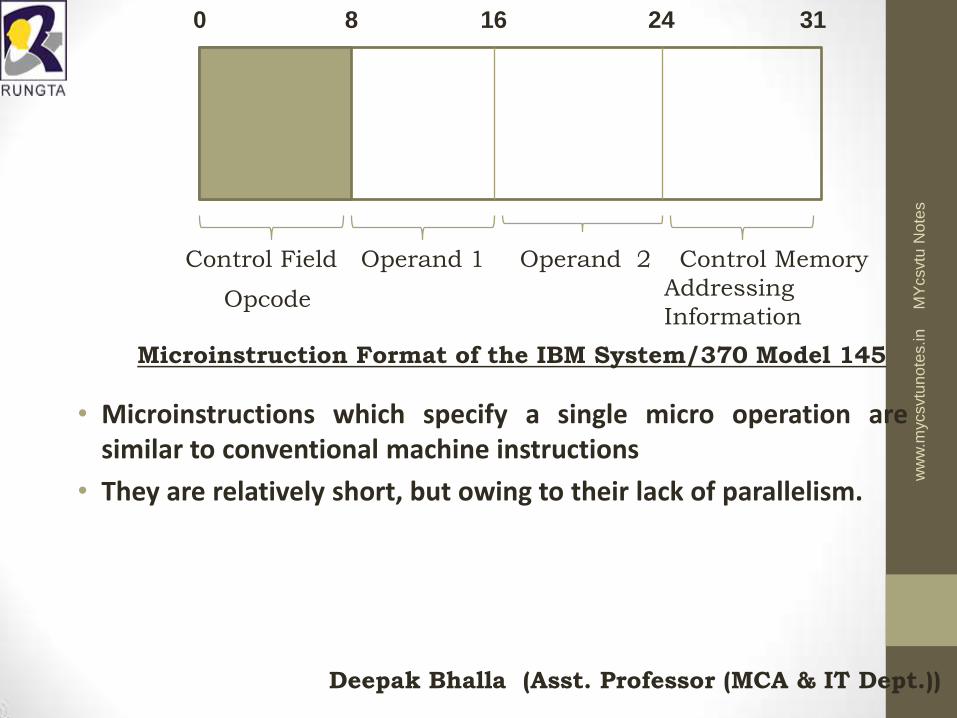
• Microinstructions which specify a single micro operation are similar to conventional machine instructions
• They are relatively short, but owing to their lack of parallelism.
0 8 16 24 31
Control Field Operand 1 Operand 2 Control Memory
Addressing
Information Opcode
Microinstruction Format of the IBM System/370 Model 145
MY
csvtu
Note
s
ww
w.m
ycsvtu
no
tes.in

Deepak Bhalla (Asst. Professor (MCA & IT Dept.))
• The format of IBM system/370 model 145 which is shown in figure above is representative of this type of micro instruction
• It consists of 4 bytes. • The leftmost byte (shaded) is an opcode which
specifies the microinstruction to be performed. • The next two bytes specify the operands which
in most cases, are the address of CPU registers. • The right most byte contains information used
to construct the address of the next micro instruction.
MY
csvtu
Note
s
ww
w.m
ycsvtu
no
tes.in

Deepak Bhalla (Asst. Professor (MCA & IT Dept.))
Micro-instruction Types
• Each micro-instruction specifies single (or few) micro-operations to be performed
• (vertical micro-programming)
• Each micro-instruction specifies many different micro-operations to be performed in parallel
• (horizontal micro-programming)
MY
csvtu
Note
s
ww
w.m
ycsvtu
no
tes.in

Deepak Bhalla (Asst. Professor (MCA & IT Dept.))
Vertical Micro-programming register
Micro-instruction Address
Function Codes
Jump
Condition
MY
csvtu
Note
s
ww
w.m
ycsvtu
no
tes.in

Deepak Bhalla (Asst. Professor (MCA & IT Dept.))
Vertical Micro-programming
• Short format
• Width is narrow
• n control signals encoded into log2 n bits
• Limited ability to express parallelism
• Considerable encoding of control information.
MY
csvtu
Note
s
ww
w.m
ycsvtu
no
tes.in

Deepak Bhalla (Asst. Professor (MCA & IT Dept.))
Horizontal Micro-programmed diag
Internal CPU Control Signals Micro-instruction Address
Jump Condition System Bus
Control Signals
MY
csvtu
Note
s
ww
w.m
ycsvtu
no
tes.in

Deepak Bhalla (Asst. Professor (MCA & IT Dept.))
Horizontal Micro-programming
• Long Format
• Wide memory word
• Ability to express High degree of parallelism
• Little encoding of control information
MY
csvtu
Note
s
ww
w.m
ycsvtu
no
tes.in

Deepak Bhalla (Asst. Professor (MCA & IT Dept.))
Sequencing Techniques
• Based on current microinstruction, condition flags, contents of IR, control memory address must be generated
• Based on format of address information
• Two address fields
• Single address field
• Variable format
MY
csvtu
Note
s
ww
w.m
ycsvtu
no
tes.in

Deepak Bhalla (Asst. Professor (MCA & IT Dept.))
Address Generation
• Explicit Implicit
• Two-field Mapping
• Unconditional Branch Addition
• Conditional branch Residual control
MY
csvtu
Note
s
ww
w.m
ycsvtu
no
tes.in

Deepak Bhalla (Asst. Professor (MCA & IT Dept.))
Execution
• The cycle is the basic event
• Each cycle is made up of two events
• Fetch
• Determined by generation of microinstruction address
• Execute
MY
csvtu
Note
s
ww
w.m
ycsvtu
no
tes.in

Deepak Bhalla (Asst. Professor (MCA & IT Dept.))
Execute
• Effect is to generate control signals
• Some control points internal to processor
• Rest go to external control bus or other interface
MY
csvtu
Note
s
ww
w.m
ycsvtu
no
tes.in

Deepak Bhalla (Asst. Professor (MCA & IT Dept.))
Control Unit Organization
MY
csvtu
Note
s
ww
w.m
ycsvtu
no
tes.in