Embed Size (px)
Citation preview

UNIT-IVDATA COMMUNICATION
TECHNIQUES

Data Link Protocols
AsynchronousProtocols
SynchronousProtocols
Character-oriented Bit-oriented
• Xmodem• Ymodem• Zmodem• BLAST• Kermit
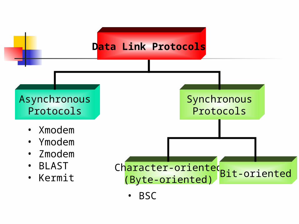
Asynchronous: treat each character in a bit stream independentlySynchronous: take whole bit stream and chop it into characters of equal size

The Use of the Word Asynchronous
Asynchronous Transmission Generally refers to the transmission
of characters with each character carrying information about timing
Asynchronous Communication Refers to overall communication
between two points An example in this case would be ATM

Asynchronous Transmission Applied to Characters
Stop Bit Start Bit
Each character is individually timed.
Character Frame

Asynchronous Transmission Applied to Packets
Packets of data Packets of data
Burst of Data
A B
Intermittent transmission of packets of data

Asynchronous Transmission/Communication Application
Character by character transmission
Data packet transmission at present
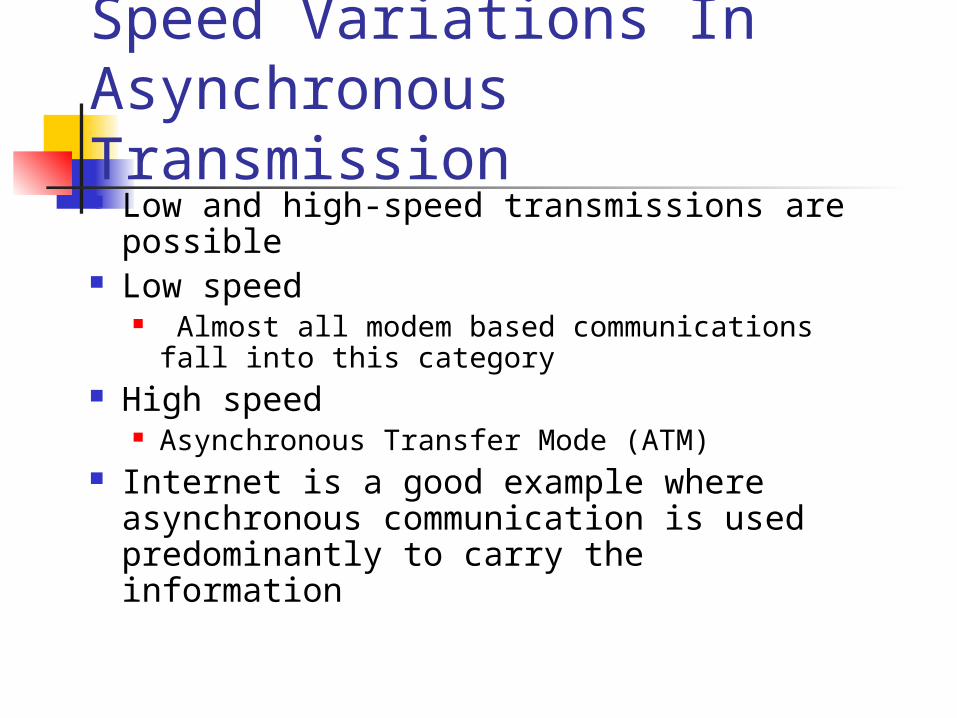
Speed Variations In Asynchronous Transmission Low and high-speed transmissions are
possible Low speed
Almost all modem based communications fall into this category
High speed Asynchronous Transfer Mode (ATM)
Internet is a good example where asynchronous communication is used predominantly to carry the information

Asynchronous Protocols Long, long…time ago Not complex and easy to implement Slow Required start/stop bit and space Now mainly used in modem Replaced by high speed
synchronous

Data Link Protocols
AsynchronousProtocols
SynchronousProtocols
Character-oriented(Byte-oriented)
Bit-oriented
• Xmodem• Ymodem• Zmodem• BLAST• Kermit
• BSC

Ymodem data unit changes to 1024 bytes (Xmodem=128)
use CRC16multiple files accepted
Zmodem combination of X and Ymodem
BLAST (Blocked Asynchronous Transmission) better than
Xmodem (full-duplex, sliding window flow conrol)
Kermit (Columbia U) most widely used asyn. Protocol (operation same as Xmodem)

Synchronous Protocols Character-oriented protocol
Based on one byte (8-bit) Use ASCII for control character Not efficient seldom used
Bit-oriented protocol Based on individual bits One or multiple bits for control More efficient

Binary Synchronous Communication (BISYNC)OR (BSC)
Character-oriented protocol Half-duplex, stop-and-wait ARQ 2 frame types
Data frame (data transmission) Control frame (connect/disconnect and flow/error
control)

A simple BSC data frame
SYN = Synchronous idle = 0010110STX = Start of text = 0000010ETX = End of text = 0000011
SYN : Alert the receiver for the incoming frameBCC : can be LRC (longitudinal redundancy check) or CRC (cyclic redundancy check)This simple frame is seldom used

A BSC frame with a header
Header Fields:• address (sender/receiver)• #frame identifier (0/1 for stop-and-wait ARQ)

A multiblock frame
ITB = Intermediate text block
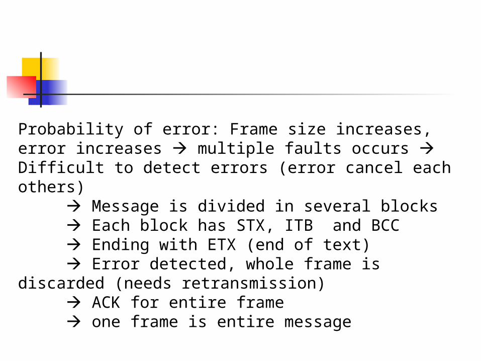
Probability of error: Frame size increases, error increases multiple faults occurs Difficult to detect errors (error cancel each others)
Message is divided in several blocks Each block has STX, ITB and BCC Ending with ETX (end of text) Error detected, whole frame is discarded
(needs retransmission) ACK for entire frame one frame is entire message

Multiframe transmission
ETB = End of transmission Block
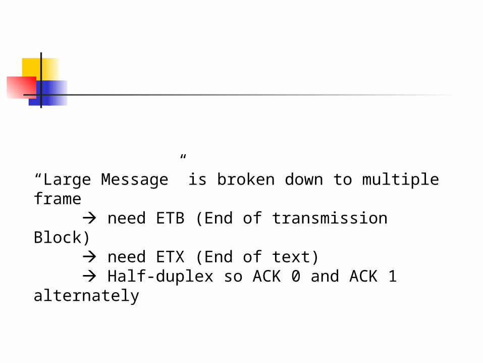
“Large Message” is broken down to multiple frame need ETB (End of transmission Block) need ETX (End of text) Half-duplex so ACK 0 and ACK 1
alternately

Control frame
Note: Control Frame is used to send command * Establish connection * Maintaining flow & error control * terminating connection
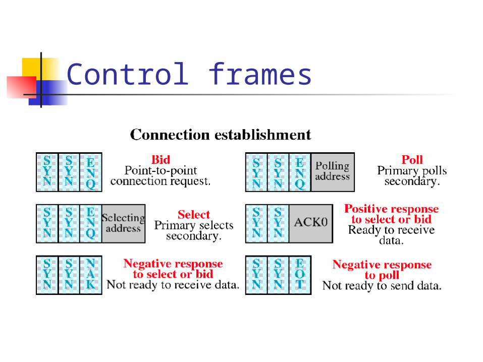
Control frames

Control frames

Control frames

Data Transparency BSC is designed for text message Now, non-text message (graphics,…)
Problem? BSC control character problem
Data transparency: should be able to send any data

Byte stuffing
DLE = data link escape

Byte Stuffing 2 activities:- Defining the transparent text region with
DLE- Preceding any DLE character within the
transparent region (extra DLE)Problem still exist if text = DLE ?
Insert an addition DLE next to the character (DLE DLE)
Data Link Protocols
AsynchronousProtocols
SynchronousProtocols
Character-oriented(Byte-oriented)
Bit-oriented
• Xmodem• Ymodem• Zmodem• BLAST• Kermit
• BSC

Bit-oriented protocol Represent more information into
shorter frame Avoid the transparency problems
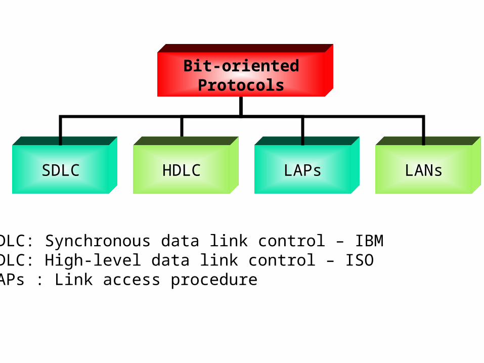
Bit-orientedProtocols
SDLC HDLC LAPs LANs
SDLC: Synchronous data link control – IBMHDLC: High-level data link control – ISOLAPs : Link access procedure

HDLC Support half/full – duplex over
point-to-point and multipoint links HDLC system characterization
Station types Configurations Communication modes
Frames

HDLC station types Primary station
The station that controls the medium by sending “command”
Secondary station The station that “response” to the primary
station Combined station
The station that can both command and response

HDLC configurations The relationship of hardware
devices on a link 3 configurations of all stations
(primary/secondary/combined) Unbalanced Symmetrical Balanced

HDLC Configurations: Unbalanced (master/slave)

HDLC Configurations: Symmetrical

HDLC Configurations:Balanced
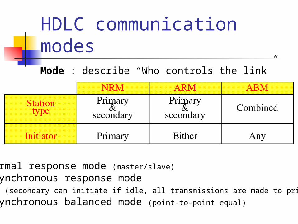
HDLC communication modes
NRM: Normal response mode (master/slave)
ARM: Asynchronous response mode (secondary can initiate if idle, all transmissions are made to primary station)
ABM: Asynchronous balanced mode (point-to-point equal)
Mode : describe “Who controls the link”

HDLC frame 3 frame types
Information frame (I-frame) Supervisory frame (S-frame)
For ACK, Flow/Error controls Unnumbered frame (U-frame)
For Mode setting, Initialize, Disconnect

HDLC Frame

HDLC Frame

HDLC Frame: Flag field
Flag: beginning and ending of a frame Last flag can be the start of the next flag
Flag similar to “Control Character” problem for transparency !!! Bit
Stuffing

Bit Stuffing How to differentiate data and flag? Adding one extra 0 whenever there are
five consecutive 1s in the data
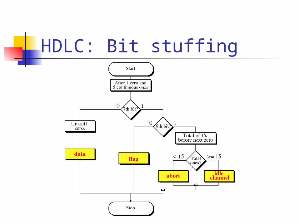
HDLC: Bit stuffing

HDLC frame: Address field Primary station creates a frame destination address Secondary station creates a frame source address Can be one byte or more

HDLC Frame: Address field

HDLC Frame: Control field

N(R) can be think as “ACK”if correct N(R) = next frame seqelse N(R) = number of damaged frame
(need reTx)In S-Frame not transmit data, so do not need N(S)
S-Frame for response (return N(R) )Code flow and error control information

HDLC frame: Poll / Final
P/F: dual purposes1) P/F = 0 no meaning (regular data)2) P/F = 1 means “poll” when send by primary P/F = 1 means “final” when send by
secondary

HDLC Frame: Information field

HDLC Frame: FCS field
FCS: Frame check sequence

HDLC: S-Frame

HDLC: Use of P/F field

HDLC: Use of P/F field
Piggybacking: data + ack

HDLC: Use of P/F field

HDLC: Use of P/F field

HDLC: S-FrameAcknowledgement

HDLC: S-Frame Positive Acknowledgement RR
Receiver sends “Positive Ack” (no data to send)
N(R) = seq of next frame RNR
Receiver sends “Positive Ack” N(R) = seq of next frame Receiver tells sender that sender cannot
send any frame until ‘RR’ frame is received

HDLC: S-Frame Negative Acknowledgement
Reject (REJ) Go-back-n ARQ N(R) = # of damage frame (and
follow) Selective-Reject (SREJ)
N(R) = # of damage frame
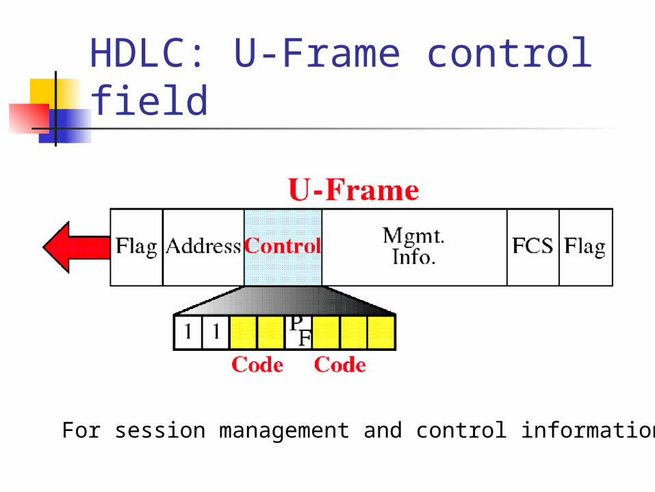
HDLC: U-Frame control field
For session management and control information

HDLC: U-Frame control field

HDLC: Polling example

HDLC: Selecting example

HDLC: Peer-to-peer example
SABM: Set asynchronous balanced modeUA: Unnumbered ack

HDLC: Peer-to-peer example

X.25 AND FRAME RELAY

X.25• X.25 is a packet-switching wide area network
developed by ITU-T in 1976.
• X.25 defines how a packet-mode terminal can be connected to a packet network for the exchange of data.
• X.25 is what is known as subscriber network interface (SNI) protocol.
• It defines how the user’s DTE communicates with the network and how packets are sent over that network using DCEs.

Figure 17-1
X.25
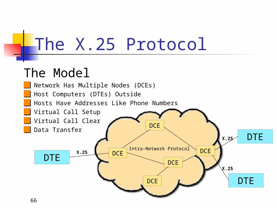
Data terminal equipment (DTE) is an end instrument that converts user information into signals or reconverts received signals. These can also be called tail circuits. A DTE device communicates with the data circuit-terminating equipment (DCE). The DTE/DCE classification was introduced by IBM.A data circuit-terminating equipment (DCE) is a device that sits between the data terminal equipment (DTE) and a data transmission circuit. It is also called data communications equipment and data carrier equipment. Usually, the DTE device is theterminal (or computer), and the DCE is a modem.In a data station, the DCE performs functions such as signal conversion, coding, and line clocking and may be a part of the DTE or intermediate equipment.
66
The X.25 Protocol
The ModelNetwork Has Multiple Nodes (DCEs)Host Computers (DTEs) OutsideHosts Have Addresses Like Phone NumbersVirtual Call SetupVirtual Call ClearData Transfer
DTE
DTE
DCE
DCE
DCE
DCEDCEX.25
X.25
X.25
Intra-Network Protocol
DTE

• X.25 network is a packet switching network that used X.25 protocol.
• X.25 is a standard packet switching protocol that has been widely used in WAN.
• X.25 is a standard for interface between the host system with the packet switching network in which it defines how DTE is connected and communicates with packet switching network.
• It uses a virtual circuit approach to packet switching (SVC and PVC) and uses asynchronous (statistical) TDM to multiplex packets.

Figure 17-2
X.25 Layers in Relation to the OSI Layers
X.25 protocol specifies three layers:
i. Physical Layer (X.21)
ii. Frame Layer (LAPB)
iii. Packet Layer (PLP) (Packet Layer Protocol)
X.25 Layers

-specifies the physical interface between the node (computer, terminal) and the link that connected to X.25 network.
-specifies a protocol called X.21 or X.21bis (interface).
-similar enough to other PHY layer protocols, such as EIA-232.
X.25 – Physical Layers

X.21 hardware interface

X.25 Frame Layer
- provides a reliable data transfer process through data link control which used link access procedure, balanced (LAPB) protocol.
- there are 3 categories of frame involved in the LAPB frame format:
I-Frames – encapsulate PLP packets from the network layer and before being passed to the physical layer

Figure 17-3
Format of a Frame in X.25
Cont…
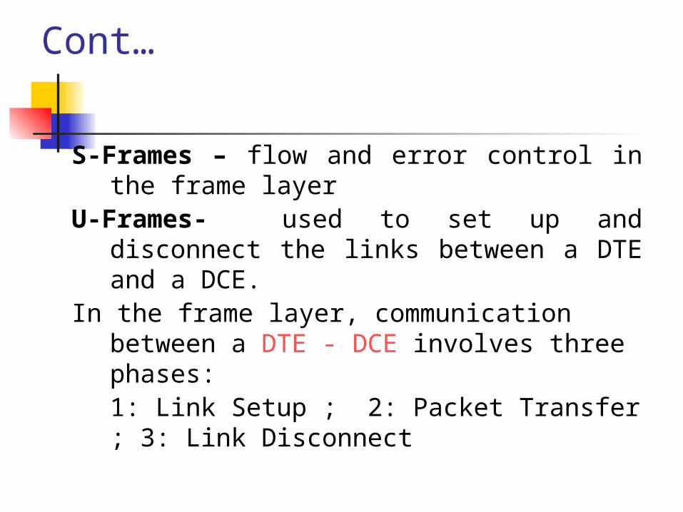
S-Frames – flow and error control in the frame layer
U-Frames- used to set up and disconnect the links between a DTE and a DCE.
In the frame layer, communication between a DTE - DCE involves three phases: 1: Link Setup ; 2: Packet Transfer ; 3: Link Disconnect

Figure 17-6
Frame Layer and Packet Layer Domains

The X.25 ProtocolLAPB Link Setup and Disconnect
Local DCE
Local DTE
SABM
UA
•SABM = Set Asynchronous Balanced Mode
•UA Acknowledges SABM
•DISC Requests Disconnect
•UA Acknowledges DISC
•Exchange on Local Link Only
DISC
UA
Now in Data Transfer Mode
Now in Disconnected Mode

The X.25 ProtocolLAPB Data Transfer
Local DCE
Local DTE
I-Frame #1
RR N(R)=2
•I-Frame Contains Packet•Seq from 0 - 7 and back to 0•RR Gives Next Expected I-Frame•I-Frame Can also Acknowledge
I-Frame #2
RR N(R)=3
I-Frame #3
I-Frame #0 N(R)=4

X.25 Packet layer (PLP)
Packet Layer Protocol (PLP) - it is the network layer in X.25- this layer is responsible for establishing the connection, transferring the data, and terminating the connection between 2 DTEs. - it also responsible for creating the virtual circuits and negotiating network services between two DTEs.
• Virtual circuits in X.25 are created at the network layer (not the data link layers as in some other wide area networks such as Frame Relay and ATM)
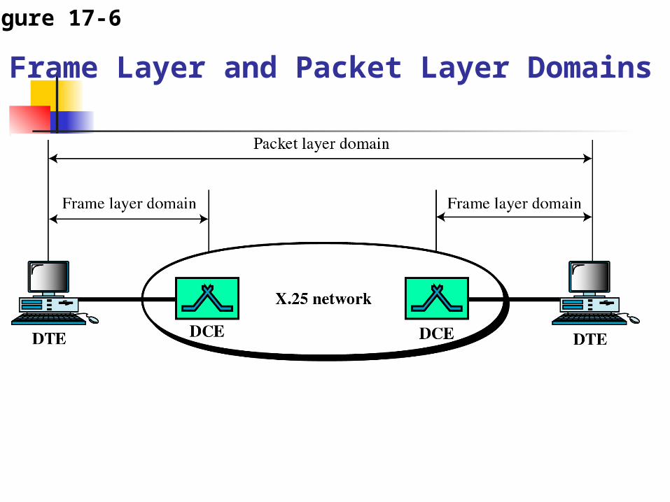
Figure 17-6
Frame Layer and Packet Layer Domains

The X.25 ProtocolCall Setup
Local DCE
Remote DCE
Local DTE
Remote DTE
Call Request
Incoming Call
Call Accepted
Call Connected
Internal Protocol
•Each Channel is Distinct
•Select Unused Channel
•Different Channel Numbers on Each End
•End to End is “Virtual Circuit”
•VC = Local Chnl + Network Route + Remote Chnl
•Internal Network Protocol Not Specified
•Call Setup is End to End
Locate Remote DCE

The X.25 ProtocolCall Clearing
Local DCE
Remote DCE
Local DTE
Remote DTE
Clear Request
Clear Indication
Clear Confirm
Clear Confirm
Internal Protocol
•Each Channel is Distinct
•Channels Become Available
•End to End is “Virtual Circuit”
•Internal Network Protocol Not Specified
•Clearing May be End to End or Local
•Clear Packet Used to Report Procedure Errors
Remote DCE from Call Setup

The X.25 ProtocolData Transfer w/End to End Ack
Local DCE
Remote DCE
Local DTE
Remote DTE
Data Packet #1
Data Packet #1
RR P(R)=2
RR P(R)=2
Internal Protocol
•Each Channel is Distinct
•End to End is “Virtual Circuit”
•Internal Network Protocol Not Specified
•Each Data Pkt Has Seq Nr
•Each RR Has Next Expected Seq Nr
•Example Shows End to End Acknowledgement
Remote DCE from Call Setup

The X.25 ProtocolData Transfer w/Local Ack
Local DCE
Remote DCE
Local DTE
Remote DTE
Data Packet #1
Data Packet #1RR P(R)=2
Internal Protocol
•Each Channel is Distinct
•End to End is “Virtual Circuit”
•Internal Network Protocol Not Specified
•Each Data Pkt Has Seq Nr
•Each RR Has Next Expected Seq Nr
•Example Shows Local Acknowledgement
RR P(R)=2
Data Packet #2
RR P(R)=3Data Packet #2
RR P(R)=3
Remote DCE from Call Setup

Implementation of X.25
• X.25 protocol is a packet-switched virtual circuit network.
• Virtual Circuit in X.25 created at the network layer. unlike Frame Relay and ATM which both VC created at Data Link Layer.
• Fig 17.7 shows an X.25 network in which 3 virtual circuits have been created between DTE A and 3 other DTEs.

Figure 17-7
Virtual Circuits in X.25

Virtual Circuit in X.25• Each virtual circuit in X.25 should be
identified for use by the packets.• The VC in X.25 is called logical
channel number (LCN). See fig 17.8

Figure 17-8LCNs in X.25

PVC and SVC in X.25• PVC = permanent Virtual Circuit• SVC = Switched virtual circuit• X.25 applied both PVC and SVC.• PVCs are established by the X.25
network providers. (similar to the leased line in telephone networks.)
• SVCs are established at each session. Involve 5 events (like 3-phase). Setup, transfer & connection released.

5 events in SVC• A Link is setup between DTE and DCE
also between REMOTE DTE and DCE• A virtual circuit is established between
the local DTE and the remote DTE.• Data are transferred between the two
DTEs.• The virtual circuit is released• The link is disconnected

Frame Relay• Packet-switching with virtual-circuit
technology• Improvement of previous technology
X.25• Operate only at the PHY and Data
link layer.

Frame Relay: Why it is needed?• Higher Data Rate at Lower Cost• Allow Bursty Data• Less Overhead Due to Improved
Transmission Media (compared to prev. tech X.25)

Higher Data Rate at Lower Cost
•Fig. Frame Relay versus Pure Mesh T-Line Network•To connect all the highspeed LANs, it is better used frame-relay network rather than T-Line Network which cost a lot of money and impractical

Frame Relay Operation• Frame relay provides permanent
virtual and switched virtual circuit connections (PVC and SVC)
• The devices that connects users to the network are DTEs.
• The switches that route the frames thru the network are DCEs (see fig 18.5)

Figure 18-5Frame Relay Network

Virtual Circuit in FR• FR is a virtual circuit network. It
therefore does not use PHY addresses to define the DTEs connected to the network.
• It uses VCI called Data Link Connection Identifier (DLCI).
• DLCI is assigned to the DTEs when Virtual Circuit is established for connection

Figure 18-6DLCIs

FR Operation: SVC and PVC• It uses a virtual circuit identifier that is known as data
link connection identifier (DLCI).• Two types of connection:
1. Permanent virtual connection (PVC)• The connection is already exist for 2 DTE in the
network• 2 DLCI is given for each end of the connection
2. Switched virtual connection (SVC)• Everytime when one DTE needs to connect to
other DTE, VC will be established. It needs a protocol that has network layer function and network layer addressing like IP.
• Generally, local DTE will send a SETUP message to the remote DTE which will response by sending message CONNECT.
• VC will be establish for sending the data• Message RELEASE is sent to terminate the
connection.

Figure 18-7
PVC DLCIs

Figure 18-9SVC DLCIs

Figure 18-8
SVC Setup and Release

Figure 18-13Comparing Layers in Frame Relay and X.25

Figure 18-25FRAD
To handle frames arriving from other protocols, Frame Relay uses a device called a FRAD.
A FRAD assembles and disassembles frames coming from other protocols to allow them to be carried by Frame Relay frames.
A FRAD can be implemented as a separate device or as part of a switch.

Figure 12.3 Frame Relay frame

Adv of Frame Relay tech.• Higher speed than X.25 (44.376 Mbps)• Application that used TCP/IP protocol such
as email/http/chat can easily use Frame relay as it backbone bcoz FR operates at only 2 layer (DL and PHY).
• Allow bursty data• Allow frame size of 9000 bytes, which can
accommodate all LAN frames• Less expensive compared to other WANs
tech.

Disadv. Of Frame Relay• Max. transfer rate is at 44.376. Not enuff
speed compared to nowadays demand• allows variable-length frames which may
cause varying delays for different users.• Because of the varying delays, which are
not under user control, Frame relay is not suitable for sending delay sensitive data such as real time voice or video. E.g. FR not suitable for teleconferencing.


![[MS-SPO]: SharePoint Protocols OverviewMS-SPO... · SharePoint Protocols Overview ... 2018 [MS-SPO]: SharePoint Protocols Overview This overview describes the SharePoint Protocols](https://img.dokumen.tips/doc/110x75/5ece03cb25b3922c1e1461bd/ms-spo-sharepoint-protocols-overview-ms-spo-sharepoint-protocols-overview.jpg)