Embed Size (px)
Citation preview
316482 Automotive Electrical & Electronics A J Bhosale
Government College of Engineering and Research, Avsari (Kd)
Unit -IV
Automotive Sensors & Actuators
By,
Mr. A J Bhosale
Asst. Professor
Dept. of Automobile Engineering
Govt. College of Engineering and Research, Avsari (Kd)

316482 Automotive Electrical & Electronics A J Bhosale
Government College of Engineering and Research, Avsari (Kd)
Syllabus:
Working principle of sensors, Types of sensors, Airflow
rate sensor, Position sensor, Throttle angle sensor,
Temperature sensor, MAP sensors, Knock/Detonation
Sensor, Load cell, Lambda Sensor(Exhaust gas O2
Sensor), yaw rate sensor, sensor feedback control,
Electronic Control Unit (ECU), Principle of actuator,
Types of actuators, engine control actuators, Solenoid
actuators, motorized actuators (Stepper motors).

316482 Automotive Electrical & Electronics A J Bhosale
Government College of Engineering and Research, Avsari (Kd)
Sensors:
Sensors are the components ofthe system that provide the inputsthat enable the computer (ECM)to carry out the operations thatmake the system functioncorrectly.
In the case of vehicle sensors it isusually a voltage that isrepresented by a code at thecomputer’s processor. If thisvoltage is incorrect the processorwill probably take it as an invalidinput and record a fault.

316482 Automotive Electrical & Electronics A J Bhosale
Government College of Engineering and Research, Avsari (Kd)
Types of Sensors used
1. Mass air flow (MAF) rate
2. Exhaust gas oxygen concentration (possibly heated)
3. Throttle plate angular position
4. Crankshaft angular position/RPM
5. Coolant temperature
6. Intake air temperature
7. Manifold absolute pressure (MAP)
8. Differential exhaust gas pressure
9. Vehicle speed
10. Transmission gear selector position

316482 Automotive Electrical & Electronics A J Bhosale
Government College of Engineering and Research, Avsari (Kd)
Mass air flow (MAF) rate sensor
Airflow sensors are used on engines with multiportelectronic fuel injection. This is because the amount of fueldelivered by an EFI system is controlled by a computer(powertrain control module or PCM) which turns the fuelinjectors on and off.
The airflow sensor keeps the computer informed about howmuch air is being pulled into the engine past the throttleplates. This input along with information from other enginesensors allows the computer to calculate how much fuel isneeded.
The computer then increases or decreases injector duration(on time) to provide the correct air/fuel ratio.
Types: 1. Vane type Air Flow Rate Sensor
2. Hot Wire type Air Flow Rate Sensor

316482 Automotive Electrical & Electronics A J Bhosale
Government College of Engineering and Research, Avsari (Kd)
Vane type air flow (MAF) rate sensor
An engine requires the correct air–fuelratio to suit various conditions. Withelectronic fuel injection the ECM controlsthe air–fuel ratio and in order to do this itneeds a constant flow of information aboutthe amount of air flowing to the engine.
With this information, and data stored in itsmemory, the ECM can then send out asignal to the injectors, so that they providethe correct amount of fuel.
Air flow measurement is commonlyperformed by a ‘flap’-type air flow sensor.The air flow sensor shown in Figure A.uses the principle of the potential divider(potentiometer).
Fig. A
Fig. B

316482 Automotive Electrical & Electronics A J Bhosale
Government College of Engineering and Research, Avsari (Kd)
Figure B. shows the theoretical form of a simple
potential divider. A voltage, say 5 V, is applied across
terminals A and B. C is a slider which is in contact with
the resistor and a voltmeter is connected between A and
C. The voltage VAC is related to the position of the slider
C in the form VAC =VAB * x/l.
In the air flow sensor, the moving probe (wiper) of the
potential divider is linked to the pivot of the measuring
flap so that angular displacement of the measuring flap
is registered as a known voltage at the potentiometer.

316482 Automotive Electrical & Electronics A J Bhosale
Government College of Engineering and Research, Avsari (Kd)
Figure shows a simplified form of the airflow sensor. The closed position of themeasuring flap will give a voltage ofapproximately zero, and when fully open thevoltage will be 5 V.
Intermediate positions will give voltagesbetween these values. In practice, it is notquite as simple as this, because allowancemust be made for other contingencies.
A vane airflow sensor is located ahead ofthe throttle and monitors the volume of airentering the engine by means of a spring-loaded mechanical flap. The flap is pushedopen by an amount that is proportional tothe volume of air entering the engine.

316482 Automotive Electrical & Electronics A J Bhosale
Government College of Engineering and Research, Avsari (Kd)
The flap has a wiper arm that rotates against a sealed
potentiometer (variable resistor or rheostat), allowing the
sensor's resistance and output voltage to change according to
airflow.
The greater the airflow, the further the flap is forced open.
This lowers the potentiometer's resistance and increases the
voltage return signal to the computer.
A compensation plate acts as a shock absorber to prevent
rapid movement or vibrations of the measuring plate.
A sealed idle mixture screw is also located on the airflow
sensor. This controls the amount of air that bypasses the flap,
and consequently the richness or leanness of the fuel
mixture.

316482 Automotive Electrical & Electronics A J Bhosale
Government College of Engineering and Research, Avsari (Kd)
VANE AIRFLOW SENSOR PROBLEMS
Vane airflow sensors as well as all the other types of airflowsensors can't tolerate air leaks. Air leaks downstream ofthe sensor can allow "unmetered" or "false" air to enter theengine. The extra air can lean out the fuel mixture causing avariety of driveability problems, including lean misfire,hesitation and stumbling when accelerating, and a roughidle.
Dirt can also cause problems. Unfiltered air passingthrough a torn or poor fitting air filter can allow dirt to buildup on the flap shaft of a vane airflow sensor causing the flapto bind or stick. The operation of the flap can be tested bygently pushing it open with a finger. It should open and closesmoothly with even resistance. If it binds or sticks, a shot ofcarburetor cleaner may loosen it up otherwise the sensor willhave to be replaced.

316482 Automotive Electrical & Electronics A J Bhosale
Government College of Engineering and Research, Avsari (Kd)
Backfiring in the intake manifold can force the flap
backwards violently, often bending or breaking the
flap. Some sensors have a "backfire" valve built into the
flap to protect the flap in case of a backfire by venting
the explosion. But the anti-backfire valve itself can
become a source of trouble if it leaks. A leaky backfire
valve will cause the sensor to read low and the engine to
run rich.

316482 Automotive Electrical & Electronics A J Bhosale
Government College of Engineering and Research, Avsari (Kd)
Hot Wire Type MAF:
The hot wire MAF sensor is a variationof a classic air flow sensor that wasknown as a hot wire anemometer andwas used, for example, to measure windvelocity for weather forecasting.
In this MAF, the hot-wire, or sensing,element is replaced by a hot-filmstructure mounted on a substrate.
On the air inlet side is mounted ahoneycomb flow straightener that“smooths” the air flow (causingnominally laminar air flow over the filmelement). At the lower portion of thestructure is the signal processingcircuitry.

316482 Automotive Electrical & Electronics A J Bhosale
Government College of Engineering and Research, Avsari (Kd)
The film element is electrically heated to a constanttemperature above that of the inlet air.
The hot-film element is incorporated in a Wheatstone bridgecircuit (Figure at top).
The power supply for the bridge circuit comes from anamplifier.

316482 Automotive Electrical & Electronics A J Bhosale
Government College of Engineering and Research, Avsari (Kd)
The Wheatstone bridge consists of three fixed resistors R1,R2, and R3 and a hot-film element having resistance RHW.With no air flow the resistors R1, R2, and R3 are chosen suchthat voltage va and vb are equal (i.e., the bridge is said to bebalanced).
As air flows across the hot film, heat is carried away fromthe film by the moving air. The amount of heat carried awayvaries in proportion to the mass flow rate of the air.
The heat lost by the film to the air tends to cause theresistance of the film to vary, which unbalances the bridgecircuit, thereby producing an input voltage to the amplifier.
The output of the amplifier is connected to the bridge circuitand provides the power for this circuit. The amplifiedvoltage changes the resistance in such a way as to maintain afixed hot-film temperature relative to the inlet temperature.

316482 Automotive Electrical & Electronics A J Bhosale
Government College of Engineering and Research, Avsari (Kd)
The amplifier output voltage vc varies with MAF and
serves as a measure of Rm. Typically the conversion of
MAF to voltage is slightly nonlinear, as indicated by the
calibration curve depicted in Figure.
Fortunately, a modern digital engine controller can
convert the analog bridge output voltage directly to mass
air flow by simple computation.

316482 Automotive Electrical & Electronics A J Bhosale
Government College of Engineering and Research, Avsari (Kd)
Hot Wire MAF sensors have no moving parts. Unlike a vaneairflow meter that uses a spring-loaded flap, mass airflow sensorsuse electrical current to measure airflow.
The sensing element, which is either a platinum wire (hot wire)or nickel foil grid (hot film), is heated electrically to keep it acertain number of degrees hotter than the incoming air.
In the case of hot film MAFs, the grid is heated to 75oC aboveincoming ambient air temperature. With the hot wire sensors, thewire is heated to 100 oC above ambient temperature.
As air flows past the sensing element, it cools the element andincreases the current needed to keep the element hot. Because thecooling effect varies directly with the temperature, density andhumidity of the incoming air, the amount of current needed tokeep the element hot is directly proportional to the air "mass"entering the engine

316482 Automotive Electrical & Electronics A J Bhosale
Government College of Engineering and Research, Avsari (Kd)
Positions Sensors:
The positions sensors are generally speed sensors ofdifferent working principle used for detecting theposition of different parameters.
Parameters Measured,
1. Crankshaft Position Sensor
2. Camshaft Position Sensor
3. ABS Wheel Sensors
4. Vehicle Speed Sensor
Working Principles used,
1. Magnetic Reluctance (Variable Reluctance) type
2. Hall Effect type
3. Optical Type

316482 Automotive Electrical & Electronics A J Bhosale
Government College of Engineering and Research, Avsari (Kd)
Crankshaft Position Sensor:
A crank position sensor is a component used in an
internal combustion engine to monitor the position or
rotational speed of the crankshaft. This information is
used by engine management systems to control ignition
system timing and other engine parameters.

316482 Automotive Electrical & Electronics A J Bhosale
Government College of Engineering and Research, Avsari (Kd)
Magnetic Reluctance (or Variable Reluctance)type sensor
This type of sensor is used in many vehicleapplications, such as ignition systems, enginespeed sensors for fuelling, and wheel speedsensors for anti-lock braking etc.
Air has a greater reluctance (resistance tomagnetism) than iron and this fact is made use ofin many sensors. The basic principle of operationof a variable reluctance type sensor (Fig. 5.1) maybe understood from the following description.
The principal elements of the sensor are: an iron rotor with lobes on it;
a permanent magnet;
a metallic path (the pole piece) for carrying the magnetic flux;
a coil, wound around the metallic path, in which a voltage is induced.

316482 Automotive Electrical & Electronics A J Bhosale
Government College of Engineering and Research, Avsari (Kd)
The reluctor disc has a number of tabs on it and these tabsare made to move through the air gap in the magnetic circuit.
The movement of the reluctor tabs, through the air gap isachieved by rotation of the reluctor shaft. The voltageinduced in the sensor coil is related to the rate of change ofmagnetic flux in the magnetic circuit.
The faster the rate of change of magnetic flux the larger willbe the voltage that is generated in the sensor coil. When themetal tab on the reluctor rotor is outside the air gap, thesensor voltage is zero.
As the tab moves into the air gap the flow of magnetism(flux) increases rapidly. This causes the sensor voltage toincrease, quite quickly, to a maximum positive value. Figure5.2 shows the approximate behavior of the voltage output asthe reluctor is rotated.

316482 Automotive Electrical & Electronics A J Bhosale
Government College of Engineering and Research, Avsari (Kd)
Figure 5.2(a) shows the reluctor tab moving into the air gap.
As the metal tab moves further into the gap the voltage
begins to fall and, when the metal tab is exactly aligned with
the pole piece, the sensor voltage falls back to zero
(Although the magnetic flux is strongest at this point, it is
not changing and this means that the voltage is zero.)
Figure 5.2(b) shows that
there is zero voltage when
the reluctor tab is in
alignment with the pole
piece.

316482 Automotive Electrical & Electronics A J Bhosale
Government College of Engineering and Research, Avsari (Kd)
As the metal tab continues to rotate out of the air gap
and away from the pole piece, the rate of change of the
magnetic flux is rapid, but opposite in direction to when
the tab was moving into the air gap.
This results in the negative half of the voltage waveform
as shown in Fig. 5.2(c). When the tab has moved out of
the air gap the sensor voltage returns to zero. While the
rotor shaft continues to turn another tab will enter the air
gap and the above process will be repeated.
If the sensor coil is connected to an oscilloscope the
pattern observed will be similar to that shown in Fig.
5.2(d).

316482 Automotive Electrical & Electronics A J Bhosale
Government College of Engineering and Research, Avsari (Kd)
316482 Automotive Electrical & Electronics A J Bhosale
Government College of Engineering and Research, Avsari (Kd)
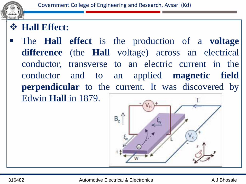
Hall Effect:
The Hall effect is the production of a voltage
difference (the Hall voltage) across an electrical
conductor, transverse to an electric current in the
conductor and to an applied magnetic field
perpendicular to the current. It was discovered by
Edwin Hall in 1879.

316482 Automotive Electrical & Electronics A J Bhosale
Government College of Engineering and Research, Avsari (Kd)
2. Hall Effect type sensor:
Figure shows the principle of a Hall type sensor. The
Hall element is a small section of semiconductor
material such as silicon.
When connected as shown in Fig.(a), the battery will
cause current to flow through the semiconductor Hall
element and battery circuit, but there will be no current
in the circuit which is at right angles to the battery
circuit, as shown by a zero reading on the voltmeter.

316482 Automotive Electrical & Electronics A J Bhosale
Government College of Engineering and Research, Avsari (Kd)

316482 Automotive Electrical & Electronics A J Bhosale
Government College of Engineering and Research, Avsari (Kd)
When a magnetic field is imposed on the Hall element,
as shown in Fig. (b), a current will flow in circuit 2.
When the magnetic effect is prevented from reaching
the Hall element, as in Fig.(c), the current will cease to
flow in circuit 2.
The result is that the current in circuit 2 can be switched
on and off by shielding the Hall element from the
magnetic field.

316482 Automotive Electrical & Electronics A J Bhosale
Government College of Engineering and Research, Avsari (Kd)

316482 Automotive Electrical & Electronics A J Bhosale
Government College of Engineering and Research, Avsari (Kd)
When the metal plate that is inserted between the magnet
and the Hall element is mounted on a rotating shaft, the
Hall current can be switched on and off at any desired
frequency.
The Hall type sensor produces an output power that is
virtually constant at all speeds.
Hall effect sensors are used wherever other
electromagnetic sensors are used, e.g. engine speed and
crank position, ABS wheel sensors, camshaft (cylinder)
identification (for ignition and fuelling) etc.

316482 Automotive Electrical & Electronics A J Bhosale
Government College of Engineering and Research, Avsari (Kd)
The voltage from a Hall element is quite small and it is
common practice for Hall type sensors to incorporate an
amplifying and pulse-shaping circuit. The result is that
the sensor produces a digital signal, i.e. it is a
rectangular waveform as shown in Fig. 5.7.

316482 Automotive Electrical & Electronics A J Bhosale
Government College of Engineering and Research, Avsari (Kd)
Optical Sensor:
In a sufficiently clean environment a shaft position can alsobe sensed using optical techniques. Figure below illustratessuch a system. Again, as with the magnetic system, a disk isdirectly coupled to the crankshaft.
This time, the disk has holes in it that correspond to thenumber of tabs on the disks of the magnetic systems.
Mounted on each side of the disk are fiber-optic light pipes.The hole in the disk allows transmission of light through thelight pipes from the light-emitting diode (LED) source to thephototransistor used as a light sensor.
Light would not be transmitted from source to sensorwhen there is no hole because the solid disk blocks thelight.

316482 Automotive Electrical & Electronics A J Bhosale
Government College of Engineering and Research, Avsari (Kd)
As shown in Figure below, the pulse of light is
detected by the phototransistor and coupled to an
amplifier to obtain a satisfactory signal level. The
output pulse level can very easily be standard transistor
logic levels of +2.4 V for the high level and +0.8 V for
the low level.
One of the problems with optical sensors is that they
must be protected from dirt and oil; otherwise, they
will not work properly.
They have the advantages that they can sense position
without the engine running and that the pulse amplitude
is constant with variation in speed.

316482 Automotive Electrical & Electronics A J Bhosale
Government College of Engineering and Research, Avsari (Kd)

316482 Automotive Electrical & Electronics A J Bhosale
Government College of Engineering and Research, Avsari (Kd)
Throttle Position Sensor:
When an engine is idling the exhaust gas
scavenging of the cylinders is poor. This
has the effect of diluting the incoming
mixture.
The ECU must detect when the throttle is
in the idling position, so that alteration of
the air–fuel ratio can occur to ensure that
the engine continues to run smoothly.
At full engine load and full throttle, the
mixture (air–fuel ratio) needs enriching,
so the ECU also needs a signal to show
that the throttle is fully open.

316482 Automotive Electrical & Electronics A J Bhosale
Government College of Engineering and Research, Avsari (Kd)
These duties are performed by the
throttle position switch. Figure 5.12
shows how the action of a throttle
position sensor is based on the principle
of the potential divider.
The sensor produces a voltage which
is related to throttle position. The
voltage signal is conducted to the
ECU where it is used, in conjunction
with other inputs, to determine the
correct fuelling for a given condition.

316482 Automotive Electrical & Electronics A J Bhosale
Government College of Engineering and Research, Avsari (Kd)
Thermistor:
Thermistors are of two opposite fundamental types:
With NTC thermistors, resistance decreases as temperaturerises. An NTC is commonly used as a temperature sensor, orin series with a circuit as an inrush current limiter.
With PTC thermistors, resistance increases as temperaturerises. PTC thermistors are commonly installed in series witha circuit, and used to protect against overcurrent conditions,as resettable fuses
Thermistors differ from resistance temperature detectors(RTDs) in that the material used in a thermistor is generallya ceramic or polymer, while RTDs use pure metals. Thetemperature response is also different; RTDs are useful overlarger temperature ranges, while thermistors typicallyachieve a greater precision within a limited temperaturerange, typically −90 °C to 130 °C

316482 Automotive Electrical & Electronics A J Bhosale
Government College of Engineering and Research, Avsari (Kd)
Temperature sensor
A commonly used device used for sensing
temperature is the thermistor. A
thermistor utilizes the concept of negative
temperature coefficient.
Most electrical conductors have a positive
temperature coefficient. This means that
the hotter the conductor gets the higher
is its electrical resistance.
This thermistor operates differently; its
resistance gets lower as its temperature
increases and this is a characteristic of
semiconductor materials.

316482 Automotive Electrical & Electronics A J Bhosale
Government College of Engineering and Research, Avsari (Kd)
There is a well-defined relationship
between temperature and resistance.
This means that current flow through the
thermistor can be used to give an accurate
representation of temperature.
Figure shows the approximate
relationship between temperature and
resistance.
The coolant temperature sensor provides
the ECU with information about engine
temperature and thus allows the ECU to
make alterations to fuelling for cold starts
and warm-up enrichment.
316482 Automotive Electrical & Electronics A J Bhosale
Government College of Engineering and Research, Avsari (Kd)
Manifold Absolute Pressure (MAP) Sensor:
Several MAP sensor configurations have been used inautomotive applications.
The earliest sensors were derived from aerospaceinstrumentation concepts, but these proved more expensivethan desirable for automotive applications and have beenreplaced with more cost-effective designs.
It is interesting to note that none of the MAP sensors in usemeasure manifold pressure directly, but instead measure thedisplacement of a diaphragm that is deflected by manifoldpressure.
The details of the diaphragm displacement and themeasurement of this displacement vary from oneconfiguration to another.

316482 Automotive Electrical & Electronics A J Bhosale
Government College of Engineering and Research, Avsari (Kd)
Strain Gauge MAP Sensor
One relatively inexpensive MAP sensorconfiguration is the silicon diaphragmdiffused strain gauge sensor shown inFigure.
This sensor uses a silicon chip that isapproximately 3 millimeters square.Along the outer edges, the chip isapproximately 250 micrometers (1micrometer = 1 millionth of a meter)thick, but the center area is only 25micrometers thick and forms adiaphragm.
The edge of the chip is sealed to a pyrexplate under vacuum, thereby forming avacuum chamber between the plate andthe center area of the silicon chip.

316482 Automotive Electrical & Electronics A J Bhosale
Government College of Engineering and Research, Avsari (Kd)
A set of sensing resistors is formed around the edge of thischamber, as indicated in Figure. The resistors are formed bydiffusing a doping impurity into the silicon.
External connections to these resistors are made throughwires connected to the metal bonding pads. This entireassembly is placed in a sealed housing that is connected tothe intake manifold by a small-diameter tube.
Manifold pressure applied to the diaphragm causes it todeflect.
The resistance of the sensing resistors changes in proportionto the applied manifold pressure by a phenomenon that isknown as piezoresistivity.
Piezoresistivity occurs in certain semiconductors so that theactual resistivity (a property of the material) changes inproportion to the strain (fractional change in length).

316482 Automotive Electrical & Electronics A J Bhosale
Government College of Engineering and Research, Avsari (Kd)
The strain induced in each resistor isproportional to the diaphragmdeflection, which, in turn, isproportional to the pressure on theoutside surface of the diaphragm. Thispressure is the manifold pressure.
An electrical signal that is proportionalto the manifold pressure is obtained byconnecting the resistors in a circuitcalled a Wheatstone bridge, as shownin the schematic of Figure a.
The voltage regulator holds a constantdc voltage across the bridge.

316482 Automotive Electrical & Electronics A J Bhosale
Government College of Engineering and Research, Avsari (Kd)
The resistors diffused into the diaphragm are denoted R1, R2,R3, and R4 in Figure a.
When there is no strain on the diaphragm, all fourresistances are equal, the bridge is balanced, and the voltagebetween points A and B is zero. When manifold pressurechanges, it causes these resistances to change in such a waythat R1 and R3 increase by an amount that is proportionalto pressure; at the same time, R2 and R4 decrease by anidentical amount.
This unbalances the bridge and a net difference voltage ispresent between points A and B. The differential amplifiergenerates an output voltage proportional to the differencebetween the two input voltages (which is, in turn,proportional to the pressure), as shown in Figure b.

316482 Automotive Electrical & Electronics A J Bhosale
Government College of Engineering and Research, Avsari (Kd)
Variable-Capacitance type MAP Sensor
Figure below gives an indication of the principle of operationof the variable capacitance type of MAP sensor.
Capacitance C = eo A/d, where eo = permittivity in a vacuum,A = area of the metallized plates and d = the distance betweenthe plates.
The metallized plates of the capacitor are placed on each sideof an evacuated capsule.
This capsule is placed in a chamber which is connected tomanifold pressure and, as the manifold pressure changes, thedistance d between the capacitor plates changes.
This change in distance between the capacitor plates causesthe value of the capacitance C to change. The capacitor isconnected into an electronic circuit that converts changes incapacitance into an electrical signal.

316482 Automotive Electrical & Electronics A J Bhosale
Government College of Engineering and Research, Avsari (Kd)

316482 Automotive Electrical & Electronics A J Bhosale
Government College of Engineering and Research, Avsari (Kd)
Variable-Inductance type MAP Sensor:
The variable-inductance type of MAP sensor relies on
the principle that the inductance of a coil is altered by
varying the position of an iron cylinder placed in the
center of the coil. Figure illustrates the principle
involved.
In this simplified
version, the iron
cylinder moves in
or out of the coil
under the influence
of the diaphragm
and spring.

316482 Automotive Electrical & Electronics A J Bhosale
Government College of Engineering and Research, Avsari (Kd)
Variations in manifold absolute pressure increase or decreasethe ‘suction’ force acting on the diaphragm and the resultantchanges in inductance are related to the manifold absolutepressure.
The coil (inductance) forms part of an electronic circuit andthis circuit is designed so that the changes in frequency ofthe square-wave output are accurate representations ofmanifold absolute pressure. Figure shows the approximateform of the variable frequency output of sensors of this type.

316482 Automotive Electrical & Electronics A J Bhosale
Government College of Engineering and Research, Avsari (Kd)
Knock Sensor:
A knock sensor that is commonly used in engine control systemsutilizes the piezoelectric generator effect, i.e. the sensing elementproduces a small electric charge when it is compressed and thenrelaxed.
Materials such as quartz and some ceramics like PZT (a mixtureof platinum, zirconium and titanium) are effective in piezoelectricapplications.
In the application shown, the knock sensor is located on theengine block adjacent to cylinder number 3 (Fig. 5.10). This is thebest position to detect vibrations arising from combustion knockin any of the four cylinders.
Because combustion knock is most likely to occur close to TDCin any cylinder, the control program held in the ECM memoryenables the processor to use any knock signal generated to alterthe ignition timing by an amount that is sufficient to eliminate theknock.

316482 Automotive Electrical & Electronics A J Bhosale
Government College of Engineering and Research, Avsari (Kd)
When knock has ceased the ECM
will advance the ignition, in steps,
back to its normal setting. The
mechanism by which vibrations
arising from knock are converted
to electricity is illustrated in Fig.
5.11.
The sensor is accurately designed
and the center bolt that pre-
tensions the piezoelectric crystal
is accurately torqued. The steel
washer that makes up the seismic
mass has very precise dimensions.

316482 Automotive Electrical & Electronics A J Bhosale
Government College of Engineering and Research, Avsari (Kd)
When combustion knock occurs, the resulting mechanical
vibrations are transmitted by the seismic mass, to the
piezoelectric crystal. The ‘squeezing up’ and relaxing of the
crystal in response to this action, produces a small
electrical signal that oscillates at the same frequency as the
knock sensor element.
The electrical signal is
conducted away from the
crystal by wires that are
secured to suitable points
on the crystal.

316482 Automotive Electrical & Electronics A J Bhosale
Government College of Engineering and Research, Avsari (Kd)
The tuning of the sensor is critical because it must be
able to distinguish between knock from combustion and
other knocks that may arise from the engine mechanism.
This is achieved because combustion knock produces
vibrations that fall within a known range of frequencies.

316482 Automotive Electrical & Electronics A J Bhosale
Government College of Engineering and Research, Avsari (Kd)
Lambda Sensor (Exhaust Gas Oxygen Sensor)
In order for the exhaust emissions catalyst to operatecorrectly, the air–fuel ratio must be kept close to 15:1 (bymass), and it is the exhaust gas oxygen (EGO) sensor thatassists the ECM to keep the air–fuel ratio within the requiredlimits.
The EGO sensor constantly monitors the oxygen content ofthe exhaust gas, and hence the air–fuel ratio at the engineintake, since the percentage of oxygen in the exhaust gas isan accurate measure of the air–fuel ratio of the mixtureentering the engine cylinders.
Figure 5.26 shows the relation between the oxygen contentof the exhaust gas and the air–fuel ratio of the mixtureentering the combustion chambers of the engine.

316482 Automotive Electrical & Electronics A J Bhosale
Government College of Engineering and Research, Avsari (Kd)
The information (voltage) from the EGOsensor is fed back to the ECM so that theamount of fuel injected into the enginemay be changed to ensure that the air–fuel ratio is kept within the requiredlimits.
It is common practice to refer to the air–fuel ratio that gives chemically correctcombustion as lambda = 1.
If the mixture is rich, lambda is less than1 (probably lambda = 0.97), and if themixture is weak, lambda is greater than1 (probably lambda = 1.03). For thisreason, the exhaust gas oxygen sensor isoften referred to as a lambda sensor.

316482 Automotive Electrical & Electronics A J Bhosale
Government College of Engineering and Research, Avsari (Kd)
THE VOLTAIC-TYPE EGO SENSOR
The voltaic, or zirconia (ZrO2), type oxygen sensor operateson the basis of a difference between the oxygen partialpressure of atmospheric air and the partial pressure ofoxygen in the exhaust gas.
At sea level, atmospheric air contains approximately 21%oxygen by weight, and this gives the oxygen a partialpressure of approximately 0.2 bar.
The oxygen content of exhaust gas varies from zero in a richmixture, to about 10% in a weak mixture, as shown inFig.5.26.
The partial pressure of the oxygen in the exhaust gastherefore ranges from near zero to approximately 0.01 bar.

316482 Automotive Electrical & Electronics A J Bhosale
Government College of Engineering and Research, Avsari (Kd)
Figure 5.27 shows that the sensor element is essentially
a cell (battery). The plates are made from platinum and
they have a layer of ceramic zirconia between them
which acts as an electrolyte.
The platinum plates act as catalysts for the oxygen
which makes contact with them, and they are also used
to conduct electricity away from the sensor.

316482 Automotive Electrical & Electronics A J Bhosale
Government College of Engineering and Research, Avsari (Kd)
The catalyzing action that takes place when oxygen contactsthe platinum plates causes the transport of oxygen ionsthrough the electrolyte and this creates the electric currentthat gives rise to the e.m.f. (voltage) of the sensor.
This sensor voltage is an accurate representation of theoxygen content of the exhaust gas.
In practice the sensing element is formed into a thimbleshape as shown in Fig. 5.28.
This type of construction exposes the maximum area ofplatinum to the exhaust gas on one side and to theatmospheric air on the other side. The platinum that isexposed to the exhaust gas is covered with a porous ceramicmaterial.
This allows the oxygen through to the platinum but protectsthe platinum against harmful contaminants in the exhaustproducts.

316482 Automotive Electrical & Electronics A J Bhosale
Government College of Engineering and Research, Avsari (Kd)

316482 Automotive Electrical & Electronics A J Bhosale
Government College of Engineering and Research, Avsari (Kd)
The greater the difference in oxygen levelsbetween the atmospheric air and the exhaustgas, the greater is the voltage produced bythe EGO sensor.
When the air–fuel ratio changes from slightlyrich, say 14:1 lambda = 0.93 to slightlyweak, 16:1 lambda = 1.06, there is a markedchange in the oxygen partial pressure of theexhaust gas and this leads to a step change inthe EGO sensor voltage because the ceramicelectrolyte (zirconia) is very sensitive tooxygen levels, as shown in Fig. 5.29.
This sudden change in sensor voltage is usedto trigger an action by the ECM, that willalter the fuelling, to maintain lambda=1(chemically correct air–fuel ratio).

316482 Automotive Electrical & Electronics A J Bhosale
Government College of Engineering and Research, Avsari (Kd)
The result of this action is that the EGO sensor output cyclesup and down, at a frequency that ensures that the engine runssmoothly and the exhaust catalyst is kept functioningcorrectly.
The actual frequency is determined by the program that thedesigner places in the ROM of the ECM. All of this meansthat a voltaic-type EGO produces a standard type of outputthat can be measured by means of equipment that is readilyavailable to vehicle repairers
The approximate shape of the voltage waveform from theEGO sensor when in operation is shown in Fig. 5.30. Thiswaveform arises from the way that the ECM alters theamount of fuel injected, i.e. lowering and raising the amountof fuel injected, in an ordered way, so as to keep the air–fuelratio within the required limits.

316482 Automotive Electrical & Electronics A J Bhosale
Government College of Engineering and Research, Avsari (Kd)
The action of the oxygen sensor is dependenton its temperature. The sensor needs to reacha temperature of around 250oC before itstarts to function at its best.
In order to assist the sensor to reach thistemperature as quickly as possible, from acold start, it is common practice to equip thesensor with a resistive-type heating element asshown in Fig. 5.31.
This means that most oxygen sensors will beequipped with four wires: a signal wire and anearth for the sensor element, and a feed wireand an earth for the heating element.
This type of sensor is known as a heatedexhaust gas oxygen sensor (HEGO)

316482 Automotive Electrical & Electronics A J Bhosale
Government College of Engineering and Research, Avsari (Kd)
ON-BOARD MONITORING OF THE CATALYTIC CONVERTER
The USA OBDII and impending European legislation requiresthat vehicle emissions systems are equipped with the facilitiesto illuminate a warning lamp (malfunction indicator lamp orMIL) should the catalytic converter cease to function correctly.In order to meet this requirement it is current practice to fit asecond oxygen sensor downstream of the catalyst, as shown inFig. 5.34.
316482 Automotive Electrical & Electronics A J Bhosale
Government College of Engineering and Research, Avsari (Kd)
In Fig. 5.34, A represents the upstream oxygen which is
on the engine side of the catalyst.
It is this sensor that provides the feedback signal that the
ECM uses to control the air–fuel ratio within the
required limits.
The second sensor at B sends a signal to the ECM that is
used to determine the efficiency of the catalyst. The
voltage amplitude of this second sensor signal is the key
to assessing the catalyst efficiency.
As the catalyst ages, or is damaged by incorrect fuel
etc., the voltage amplitude of this second sensor
increases.

316482 Automotive Electrical & Electronics A J Bhosale
Government College of Engineering and Research, Avsari (Kd)
Load Cell
A load cell is a transducer that is used to create an
electrical signal whose magnitude is directly
proportional to the force being measured.
The various types of load cells include hydraulic load
cells, pneumatic load cells and strain gauge load cells.

316482 Automotive Electrical & Electronics A J Bhosale
Government College of Engineering and Research, Avsari (Kd)
The strain gauge measures the deformation (strain) as achange in electrical resistance, which is a measure of thestrain and hence the applied forces.
Where,R : Initial resistance of the strain gauge
ΔR : Resistance change caused by elongation or contraction
K : Proportional constant (called the “gauge factor”) (ΔR/R/ΔL/L)
ε : Strain

316482 Automotive Electrical & Electronics A J Bhosale
Government College of Engineering and Research, Avsari (Kd)

316482 Automotive Electrical & Electronics A J Bhosale
Government College of Engineering and Research, Avsari (Kd)
The working principle is based on the strain/resistancerelationship of electrical conductors.
Any electrical conductor changes its resistance withmechanical stress, e.g. through tension or compressionforces. The resistance change is partially due to theconductor's deformation and partially due to the changein the resistivity of the conductor material as a result ofmicrostructural changes.
Operating Principle:
Welded Sensor utilizes bonded strain gagesconnected in Wheatstone bridge circuit. The output isderived from imbalance in the bridge circuit as load issensed by sensor.

316482 Automotive Electrical & Electronics A J Bhosale
Government College of Engineering and Research, Avsari (Kd)
Wheatstone Bridge:
Wheatstone bridge is an electric circuit suitable for
detection of minute resistance changes, therefore used
to measure resistance changes of a strain gage
The bridge is configured by combining four resistors
as shown in Fig. Initially R1=R2=R3=R4, in this condition no output
voltage is there, e=0
When one of the Resistances is replaced by strain
Gauge attached to the object whose strain is to be
measured and load is applied, then there is small
change in the resistance of gauge, hence some output
voltage is there which can be related to strain as
From this, strain can be easily determined using the relation

316482 Automotive Electrical & Electronics A J Bhosale
Government College of Engineering and Research, Avsari (Kd)
Yaw Rate Sensor:
The drive portion looks and acts exactly like a simple
tuning fork. Because the drive tines are constructed of
crystalline quartz, it is possible to electronically “ring”
this tuning fork.
Each fork tine has a mass and an instantaneous radial
velocity which changes sinusoidally as the tine moves
back and forth.
As long as the fork’s base is stationary the momenta of
the two tines exactly cancel one another and there is no
energy transfer from the tines to the base. In fact, it
takes only ~6µW of power to keep the fork ringing.
316482 Automotive Electrical & Electronics A J Bhosale
Government College of Engineering and Research, Avsari (Kd)
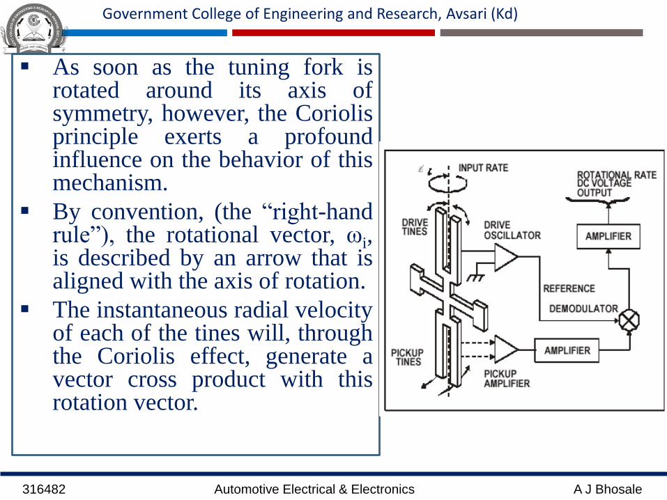
As soon as the tuning fork isrotated around its axis ofsymmetry, however, the Coriolisprinciple exerts a profoundinfluence on the behavior of thismechanism.
By convention, (the “right-handrule”), the rotational vector, ωi,is described by an arrow that isaligned with the axis of rotation.
The instantaneous radial velocityof each of the tines will, throughthe Coriolis effect, generate avector cross product with thisrotation vector.

316482 Automotive Electrical & Electronics A J Bhosale
Government College of Engineering and Research, Avsari (Kd)
The net effect is that each tine will generate a forceperpendicular to the instantaneous radial velocity of each ofthe tines:
F = 2mωi * Vr
where:– m = tine mass
– ωi = rotation rate
– Vr = radial velocity
Note that this force is directly proportional to the rotationrate, and since the radial velocity of the tines is sinusoidal,the force on each tine is also sinusoidal.
Because the radial velocities of the two tines are equal andopposite, the Coriolis forces are equal and opposite,producing an oscillating torque at the base of the drive tinefork which is proportional to the input angular rate.

316482 Automotive Electrical & Electronics A J Bhosale
Government College of Engineering and Research, Avsari (Kd)
Actuators:
Actuators are the devices, such as fuel injectors, ignitioncoils, ABS modulators etc., that are operated by outputsfrom the ECM.
Actuators normally rely on one of two electrical devices fortheir operation; they are either operated by a solenoid or byan electric motor.
Solenoid-operated actuators are normally controlled in oneof two ways. One is the duty cycle method, where thesolenoid is switched on for a percentage of the timeavailable, e.g. 20 or 80%.
This means that pulses of varying width can be used toprovide the desired result. The other method of solenoidcontrol is known as pulse width modulation (PWM). Herethe solenoid current is switched on and off at frequenciesthat change to suit operating requirements.

316482 Automotive Electrical & Electronics A J Bhosale
Government College of Engineering and Research, Avsari (Kd)
Electric motors that are used in actuators may be steppermotors, or reversible permanent magnet d.c. motors.
A stepper motor can be made to provide small movements ofvalves by pulsing the current supply.
Some stepper motors rotate 7.5° per step, which means that afull rotation of the motor shaft takes 48 steps. A commonform of stepper motor uses two sets of windings.
Current in one set of windings drives the motor shaftforward and when this is switched off and current is appliedto the other set of windings, the motor shaft rotates in thereverse direction.
This means that accurate control over the position of a valvecan be achieved because the control computer determinesthe valve position by counting the number of pulses appliedto the stepper motor windings.

316482 Automotive Electrical & Electronics A J Bhosale
Government College of Engineering and Research, Avsari (Kd)
Solenoid Valves:
A fuel injector is (in essence) a solenoid-operatedvalve. The valve opens or closes to permit orblock fuel flow to the engine. The valve isattached to the movable element of the solenoidand is switched by the solenoid activation.
In a fuel injector with no current flowing, thesolenoid movable element is held down againstthe stop, covering the aperture or nozzle.
Fuel is thereby blocked from flowing from thepressurized fuel chamber into the aperture. Whencurrent flows through the solenoid coil, themovable element is switched upward, theaperture is exposed, and fuel (under pressure)sprays through this aperture.
Figure A

316482 Automotive Electrical & Electronics A J Bhosale
Government College of Engineering and Research, Avsari (Kd)
The fuel flow rate through the
nozzle is constant for a given
regulated fuel pressure and
nozzle geometry; therefore, the
quantity of fuel injected into
the air stream is proportional
to the time the valve is open.
The control current that
operates the fuel injector is
pulsed on and off to deliver
precise quantities of fuel.
Figure B

316482 Automotive Electrical & Electronics A J Bhosale
Government College of Engineering and Research, Avsari (Kd)
Fuel Injector Signal
Consider an idealized fuel injectoras shown in Figure B, in which theinjector is open when the appliedvoltage is on and is closed when theapplied voltage is off.
In this idealization, the controlvoltage operating the fuel injector isa binary pulse train (i.e., either onor off ).
For a pulse train signal, the ratio ofon time t to the period of the pulse T(on time + off time) is called theduty cycle.
Figure C

316482 Automotive Electrical & Electronics A J Bhosale
Government College of Engineering and Research, Avsari (Kd)
This is shown in Figure C. The fuel injector is energized
for time t to allow fuel to spray from the nozzle into the
air stream going to the intake manifold. The injector is
de-energized for the remainder of the period.
Therefore, a low duty cycle, as seen in Figure C-a, is
used for a high air/fuel ratio (lean mixture), and a high
duty cycle (Figure C-b) is used for a low air/ fuel ratio
(rich mixture).

316482 Automotive Electrical & Electronics A J Bhosale
Government College of Engineering and Research, Avsari (Kd)
EGR Valve Actuator:
The exhaust gas recirculation (EGR) is utilized to reduce NOxemissions. The amount of EGR is regulated by the enginecontroller.
When the correct amount of EGR has been determined by thecontroller based on measurements from the various engine controlsensors, the controller sends an electrical signal to the EGRactuator.
Typically, this actuator is a variable-position valve that regulatesthe EGR as a function of intake manifold pressure and exhaustgas pressure. Although there are many EGR configurations, onlyone representative example will be discussed to explain the basicoperation of this type of actuator.
The example EGR actuator is shown schematically in Figure.This actuator is a vacuum-operated diaphragm valve with a springthat holds the valve closed if no vacuum is applied.

316482 Automotive Electrical & Electronics A J Bhosale
Government College of Engineering and Research, Avsari (Kd)
The vacuum that operates the diaphragm is supplied by the intake
manifold and is controlled by a solenoid-operated valve. This
solenoid valve is controlled by the output of the control system.
This solenoid operates essentially the same as that explained in the
discussion on fuel injectors. Whenever the solenoid is energized
(i.e., by current supplied by the control system flowing through the
coil), the EGR valve is opened by the applied vacuum.

316482 Automotive Electrical & Electronics A J Bhosale
Government College of Engineering and Research, Avsari (Kd)
The amount of valve opening is determined by the
average pressure on the vacuum side of the diaphragm.
This pressure is regulated by pulsing the solenoid with a
variable-duty-cycle electrical control current.
The duty cycle of this pulsing current controls the
average pressure in the chamber that affects the
diaphragm deflection, thereby regulating the amount of
EGR.

316482 Automotive Electrical & Electronics A J Bhosale
Government College of Engineering and Research, Avsari (Kd)
Petrol engine idle speed control
Idle speed control is an important element of the controlstrategy for any engine management system. The controlstrategy for engine idling must take account of factors suchas engine coolant temperature, engine load, power assistedsteering, alternator load, etc.
Many systems are fitted with an idle speed control valve thatprovides a supply of air that by-passes the throttle valve,whilst other systems may make use of the electronic throttlecontrol.
Two types of valve are used to provide a computercontrolled idle air supply. One makes use of a steppermotor, as shown in Fig. 6.12, and the other uses a solenoidoperated valve as shown in Fig. 6.15.

316482 Automotive Electrical & Electronics A J Bhosale
Government College of Engineering and Research, Avsari (Kd)

316482 Automotive Electrical & Electronics A J Bhosale
Government College of Engineering and Research, Avsari (Kd)
STEPPER MOTOR-OPERATED VALVE
Figure 6.12 shows a simplified arrangement of the extra air(air by-pass) valve that is built into the throttle body of somepetrol injection systems.
The ECU pulses the transistor bases, in the correct sequence,so that the stepper motor moves the air valve to provide thecorrect air supply, for any given condition.
In addition, other sensor signals will enable the ECU toprovide the correct amount of fuel to ensure that the enginecontinues to run smoothly. Figure 6.13 shows the steppermotor with the air valve attached.
The multiple pin connection is typical of the type ofconnection that is used to electrically connect the steppermotor to the ECU. The stepper motor can normally bechecked by operating it with the diagnostic tool connected tothe serial communication port of the ECM.

316482 Automotive Electrical & Electronics A J Bhosale
Government College of Engineering and Research, Avsari (Kd)
An oscilloscope can also be used to check the pulses
that are sent to the motor from the ECM. Figure 6.14
gives an impression of the type of result that is to be
expected from the PMS 100 oscilloscope when used to
test a stepper motor.

316482 Automotive Electrical & Electronics A J Bhosale
Government College of Engineering and Research, Avsari (Kd)

316482 Automotive Electrical & Electronics A J Bhosale
Government College of Engineering and Research, Avsari (Kd)
SOLENOID-OPERATED VALVE
This type of valve regulates the amount of air that by-passes the
throttle valve through the medium of a solenoid-operated valve
of the type shown in Fig. 6.15.
In the rest position shown, the valve (4) is closed by the spring
(5) and the armature of the solenoid (2) is pushed back inside the
solenoid coil (3). When operating, the energized solenoid opens
the valve (4) and admits air to the induction system. The quantity
of air admitted is controlled by duty cycle pulses that are sent
from the ECM.

316482 Automotive Electrical & Electronics A J Bhosale
Government College of Engineering and Research, Avsari (Kd)
Electronic Control Unit (ECU)
Figure shows the general form of a computer that consists of thefollowing parts: a central processing unit (CPU)
input and output devices (I/O)
memory
a program
a clock for timing purposes.
Data processing is one of the main functions that computersperform. Data, in computer terms, is the representation of factsor ideas in a special way that allows it to be used by thecomputer.
In the case of digital computers this usually means binary datawhere numbers and letters are represented by codes made up from0s and 1s. The input and output interfaces enable the computer toread inputs and to make the required outputs.
316482 Automotive Electrical & Electronics A J Bhosale
Government College of Engineering and Research, Avsari (Kd)
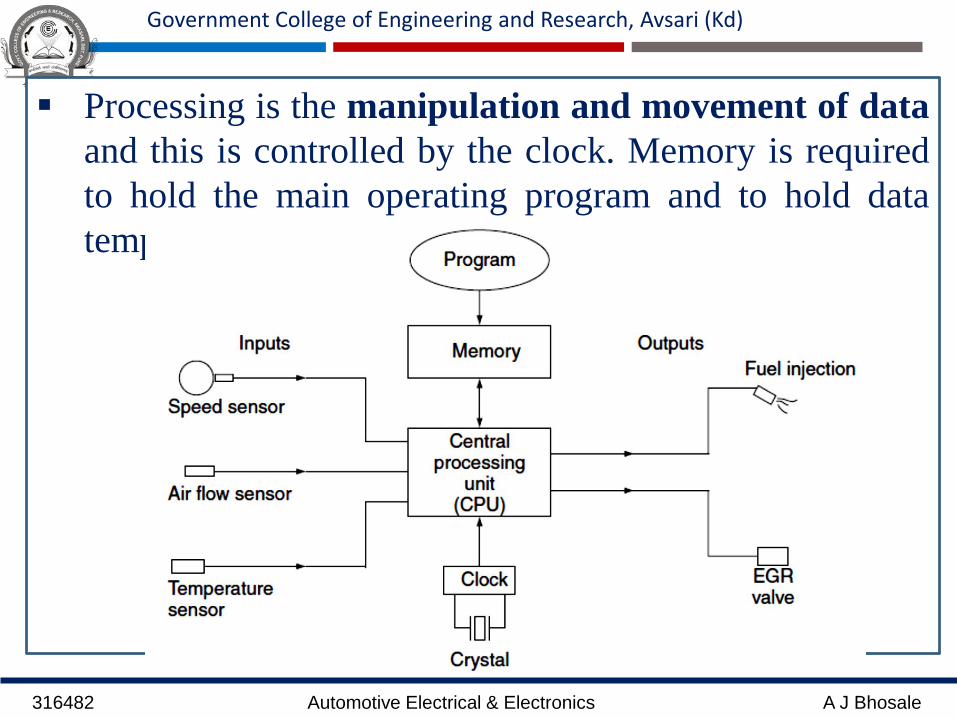
Processing is the manipulation and movement of data
and this is controlled by the clock. Memory is required
to hold the main operating program and to hold data
temporarily while it is being worked on.

316482 Automotive Electrical & Electronics A J Bhosale
Government College of Engineering and Research, Avsari (Kd)
COMPUTER MEMORY
Read only memory (ROM) is where the operating program for thecomputer is placed. It consists of an electronic circuit which givescertain outputs for predetermined input values. ROMs have largestorage capacity.
Read and write, or random access memory (RAM), is where datais held temporarily while it is being worked on by the processingunit. Placing data in memory is referred to as ‘writing’ and theprocess of using this data is called ‘reading’.
THE CLOCK
The clock is an electronic circuit that utilizes the piezoelectriceffect of a quartz crystal to produce accurately timed electricalpulses that are used to control the actions of the computer.
Clock speeds are measured in the number of electrical pulsesgenerated in one second. One pulse per second is 1 Hertz andmost computer clocks operate in millions of pulses per second.One million pulses per second is 1 megahertz (1 MHz).

316482 Automotive Electrical & Electronics A J Bhosale
Government College of Engineering and Research, Avsari (Kd)
A practical automotive ECU
Figure 2.2 shows a computer controlled transmissionsystem. At the heart of the system is an electronicmodule.
This particular module is a self-contained computerwhich is also known as a microcontroller.Microcontrollers are available in many sizes, e.g. 4, 8,16 and 32 bit, which refers to the length of the binarycode words that they work on. In this system it is an 8-bit microcontroller.
Figure 2.3 shows some of the internal details of thecomputer and the following description gives an insightinto the way that it operates.

316482 Automotive Electrical & Electronics A J Bhosale
Government College of Engineering and Research, Avsari (Kd)
The microcomputer
This is an 8-bit microcontroller.In computer language a bit is a 0or a 1. The 0 normally representszero, or low voltage, and the 1normally represents a highervoltage, probably 1.8 V.
The microcontroller integratedcircuit (chip) has a ROMcapacity of 2048 bytes (there are8 bits to one byte) and a RAMthat holds 64 bytes.
The microcontroller also has anon-chip capacity to convert fouranalogue inputs into 8-bit digitalcodes.
316482 Automotive Electrical & Electronics A J Bhosale
Government College of Engineering and Research, Avsari (Kd)
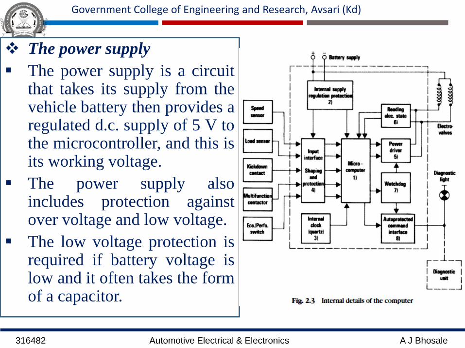
The power supply
The power supply is a circuitthat takes its supply from thevehicle battery then provides aregulated d.c. supply of 5 V tothe microcontroller, and this isits working voltage.
The power supply alsoincludes protection againstover voltage and low voltage.
The low voltage protection isrequired if battery voltage islow and it often takes the formof a capacitor.

316482 Automotive Electrical & Electronics A J Bhosale
Government College of Engineering and Research, Avsari (Kd)
The clock circuit
In this particular application the clock operates at 4 MHz.
The clock controls the actions of the computer, such as
counting sensor pulses to determine speed and timing the
output pulses to the electro-valves so that gear changes take
place smoothly and at the required time.
The input interface
The input interface contains the electronic circuits that
provide the electrical power for the sensors and switches that
are connected to it. Some of these inputs are in an electrical
form (analogue) that cannot be read directly into the
computer and these inputs must be converted into computer
(digital) form at the interface.

316482 Automotive Electrical & Electronics A J Bhosale
Government College of Engineering and Research, Avsari (Kd)
The output (power) interface
The power driver consists of power transistors that are switchedelectronically to operate electro-valves that operate the gear changehydraulics.
Feedback
At (6) on the diagram the inscription reads ‘ Reading electricalstate’. This means that the computer is being made aware of thepositions (on or off) of the electro-valves.
The watchdog
The watchdog circuit is a timer circuit that prevents the computerfrom going into an endless loop that can sometimes happen if falsereadings occur.
The diagnostic interface
The diagnostic interface is a circuit that causes a warning lamp tobe illuminated in case of a system malfunction. It can also be usedto connect to the diagnostic kit.