Embed Size (px)
Citation preview
UNIT I
SITE INVESTIGATION AND
SELECTION OF FOUNDATION
OBJECTIVES OF SITE EXPLORATIONS
• Determine the nature of the deposite of soil
• Determine the depth and thickness of various soil
• Determine the location of ground water table andthe fluctuating of ground water table
• Determine the engineering properties of soil
• To ensure the safety of surrounding existingstructures
• To know the sources of construction materials
• Selection of site for disposal of waste water

METHODS OF EXPLORATIONS
Site exploration
1.Reconnaisance
2.Priliminary
3.Detailed exploration

Reconnaisance
• It is the first method of site explorations orsubsurface investigations
• It includes to visit the site and study the mapsand other relevant records.

Priliminary
• To determine the depth thickness and thecomposition of soil strata
• It includes to determine the ground watertable

Detailed exploration
• It includes to determine the engineeringproperties of soil in various soil strata
• It includes an extensive boring programsampling and testing of sample in the lab
• Field test such as,
Vane shear test
Plate load test
Permeability test

Types of soil exploration
• The methods available for soil exploration may be classified as follow,
Direct method (test pit)
semi direct (boring or augering)
Indirect method (sounding or penetration and geophysical method)

Semi direct method
Boring and augering
Auger boring
Wash boring
Rotary boring
Pre-caussion boring
Auger and shell boring

Depth of exploration
• It required at a particular site depends upon the degree of variationof the subsurface data in the horizontal and vertical directions.
• It is not to possible to fix the number, disposition and depth ofbearings without making a few priliminary borings or surroundingsat the site. The depth of exploration is governed by the depth of theinfluence zone. The depth of influence zone depends upon the typeof the structure ,intensity of loading, shape and disposition of theloaded area the soil profile and the physical characteristics of thesoil.
• The depth up to which the stress increment due to super imposedloads can produce significant settlement and shear stresses isknown as significant depth
• D= C(S)^0.7
• C=Constant(3 for light steel structure 6 for heavy steel)
• S=Number of storeys

Lateral extent of exploration
• The lateral extent of explorations and the spacing of bore holesdepend mainly on the variation of the strata in horizontal direction
• For small and less important building even one bore hole or a trialpit is enough.
• Compact building covering an area of about 0.4 hec there should be5 bore holes one @centre and 4 corners.
• For large multi storey building bore holes should be drilled at all thecorners and also at important locations.
• The spacing between the boreholes is generally kept between 10to 30 m depending upon the variation in the sub surface
• For highways bore holes b/w 150 mm to 300mm• For concrete dams bore holes b/w 40 to 80mm

Pits and trenches
• The size of the pit should be sufficient to providenecessary working space.
• IS 4453-1967 recommends working space 1.2mX1.2m at the bottom of the pit.
• The depth of the pit depends upon therequirement of the investigation
• Shallow pits - depth of 3m without any lateralsupport
• Deeper pits – below the ground water table thelateral support in the form of bracing andsheeting

Trenches

Drifts and shafts
Drifts :
They are the horizontal tunnels made in the hill sides todetermine the nature and structure of the geologicalstrata. According to IS 4453-1980 a drift should be 1.5m wide and 2 m height in hard rock.
Shafts:
Large sized vertical holes made in the geologicalinformation are called as shafts
For circular diameter = 2.4m
For rectangular width = 2.4m

Drifts and shafts

Types of soil samples
• Disturbed samples
• Undisturbed samples

Disturbed samples

Undisturbed samples
Auger boring
• Augers are used in cohesive and soft soil above water table.In this boring there are two types of augers are used,
Hand auger (15-20mm dia)Mechanically operated auger/power given auger
Hand augers are used only for the depth of 6mMechanically operated augers are used for greater depth.This type of boring are used for gravelly soil.
The auger is advanced by rotating it while pressing it in tothe soil at the same time. The auger is filled with soil and itis taken out and then the soil sample are collected. Thesamples are used for identification purpose only,
Auger boring is purely satisfactory for highway exploration atshallow depth and for exploring barrow bit

Auger boring

Auger boring

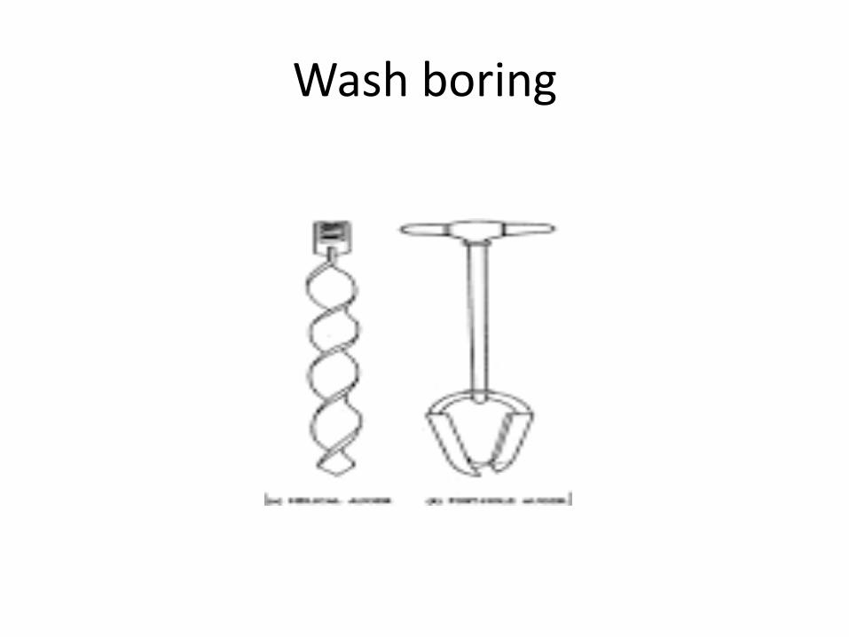
Wash boring
• Wash boring is a fast and simple method foradvancing holes in all types of soil.
• In this boring boulders and rocks cannot bepenetrated into the soil.
• This method consist of first driving a causingthrough hollow drill rod with a sharp chisel andcharping bit and a lower end is inserted
• Water is forced under pressure through a drill rodalternatively raise and drop and also rotated.

Contin..
• The cutting or forced up to the ground surface inthe form of soil water slurry through the annularspace between the drill rod and the casing. Thewater collected in the sump is used to circulatingagain.
• And then the collected samples are verydisturbed it is not very useful for determining theengineering properties.
• The changes of colour of water is to indicatechanging the soil strata.
Wash boring

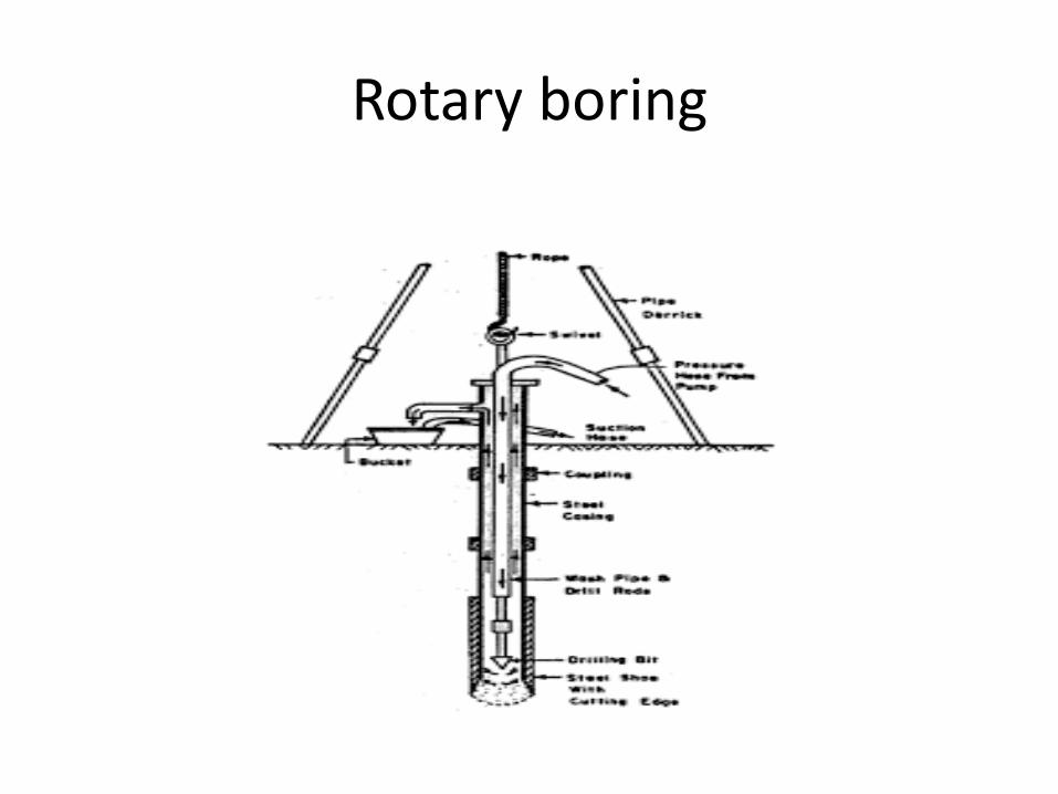
Rotary boring
• Rotary boring (or) rotary drilling is a very fastmethod of advancing hole for both rocks andsoil.
• The drill bit is fixed to the lower end of thedrill rod it is rotated by the suitable chunk.
• It is always kept in the form contact with abottom of soil. The drill mud is usually a watersolution of bentenoid with or withoutadmixtures.

Contin…
• It is continuously forced on the hollow drillrods. The mud retaining upwards bringing thecutting to the surface.
• The soil samples are collected and testing inthe laboratories.
Rotary boring

Pre-caussion boring
• It is used for making holes in rocks and other hardstrata. A heavy chisel is alternatively lifted anddropped in vertical hole.
• The materials get pulverized. The water forms aslurry with the pulverized material which isremoved by a sand pump. The main advantage isit can be used for all types of materials.
• The major disadvantages is the material at thebottom of the hole is disturbed by heavy blows ofchisel.

Precaussion boring

Auger and shell boring
• It is used for drilling holes and for obtaining rocks.A core barrel filled with a drilling bit is fixed to ahollow drilled rod.
• As the drilling rod is rotated bit and cut an hole,the core is removed from its bottom and isretained by a core lifter and brought to theground surface.
• The core barrel may consist of a single tube ordouble tube. A double tube barrel gives a goodquality sample of the rock.

Auger and shell boring

Depth of boring
• The depth of exploration depends upon the type ofProposed structuretotal weightsize of the structureshape of the structureposition of loaded areasoil profilephysical properties of soil
That constitute each and individual stratum. It shouldbe one and half times the width of footing below thefoundation level.

Types and depth of foundation
Types of foundation Depth of exploration
Isolated spread footings (or) raft (or) adjacent footing with clear spacing equal or greater than four times the width
1 ½ times the width
Adjacent footing with clear spacing less than twice the width
1 ½ times the length
Pile foundation 10 to 30 m (or) more (or) atleast (or) 1 ½ times the width of the structure
Base of retaining wall 1 ½ times the base of width
Footing basement Depth of construction
Dams 1 ½ times the bottom width of each dams
Roads cuts and fills 1m below foundation level

Depth of boring
Number of storeys Depth of boring
Single storey 3.5m depth
Two storey building 6m depth
Three 10m depth
Four 16m depth
Five 24m depth
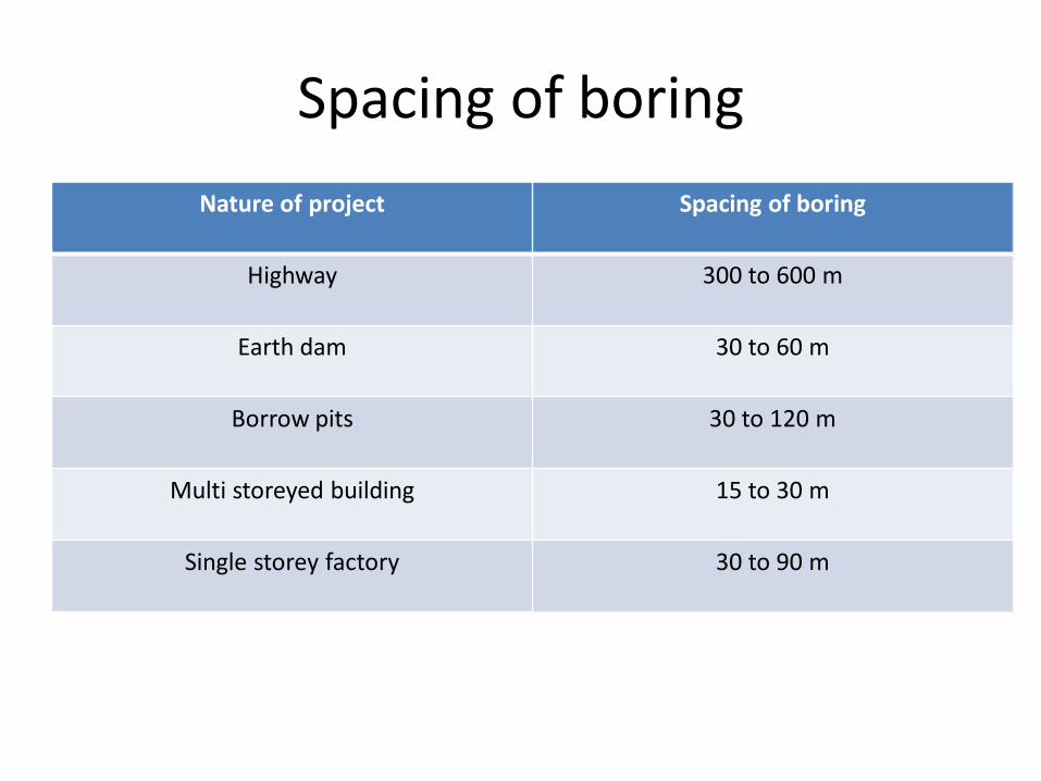
Spacing of boring
Nature of project Spacing of boring
Highway 300 to 600 m
Earth dam 30 to 60 m
Borrow pits 30 to 120 m
Multi storeyed building 15 to 30 m
Single storey factory 30 to 90 m

Design features affecting the sample
• Area ratio
• Inside clearance
• Outside clearance
• Inside wall friction
• Design of non return value
• Method of applying force
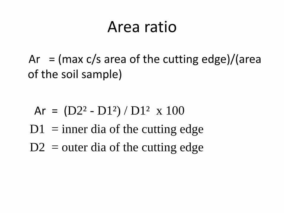
Area ratio
Ar = (max c/s area of the cutting edge)/(area of the soil sample)
Ar = (D2² - D1²) / D1² x 100
D1 = inner dia of the cutting edge
D2 = outer dia of the cutting edge

Inside clearance
Ci = (D3-D1) / D1 X100
D3 = Inner dia of sampling tube
The inside clearance allows elastic expansionof the sample when it enters the tube. It helpsto reducing the frictional drag on the samplefor an undisturbed sample the Ci between 0.5to 3%

Outside clearance
It can be defined as,
Co =(D2-D4) / D4 X100
D4 = Outer dia of the sampling tube
For reducing the driving force the outsideclearance should be small as possible. Covalue 0.02%

Inside wall friction
• The friction on the inside wall causesdisturbance of the sample.
• The inside surface of the sample should besmooth.

Design of non return value
• The non return value provided on the samplershould be of proper design. It should have anorifice of large area to allow air water or slurryto escape quickly when the sampler is driven.
• It should immediately close when the sampleris withdrawn.
Method of applying force
• The degree of disturbance depends upon themethod of applying force during sampling andupon the rate of penetration of the sampler

Method of sampler
• Split spoon sampler
• Stationery sampler
• Thin walled sampler
• Rotary sampler

Split spoon sampler
• It is basically a thick walled steel tube and it split in tolengthwise. The standard size of the split spoonsampler is of 35mm internal diameter and 50.8 mmexternal diameter.
• The sampler is an driven by forcing it in to the soil byblows from a hammer.
• The soil samples are collected in to the sampler. Thetwo half of the barrel are separated and thus exposed.
• The sample may be placed in a glass jar and sealed. Inthis sampler liner are inserted in side the split spoonsampler

Split spoon sampler

Split spoon sampler

Split spoon sampler
Stationary sampler
• It consist of simple cylinder and the piston
system. During lowering the sampler the hole
of the lower end of the sampler escaped close
with the piston.
• The desired sampling elevation is reached the
piston rod is clamp. The sampler is more
suitable for sampling soft soil and saturated
sands

Thin walled sampler
• The sampling tube shall be made of steel, brassor aluminium. The lower end of tube is level toform a cutting edge and its tapered to reducewall friction.
• The inside dia of the steel tube is 38mm andoutside dia of the tube is 40mm. The sampler islower at the bottom of the borehole by attachingit to the drill rod.
• Then the sampler is prevent by forcing it in to thesoil by blows from a hammer or a piston.

Thin walled sampler

Thin walled sampler

Penetration test
This test involves the measurement of the system to
penetration of sampling spoon, a cone (or) other
shaped tools under dynamic and static penetration.
This resistant is embrically with some engineering
properties of soil such as density index consistency
and bearing capacity. They can be classified in to 2
types,
Standard penetration test
Static cone penetration test

Standard penetration test
• The most important and most commonly used field test.This test is especially suited for cohesion less soil.
Typical equipements
• Drill rod
• Split spoon sampler
• Hammering equipement
• Casing pipe
It is useful for finding out a relative density ofcohesionless soil. And the angle of shearing resistanceof the cohesionless soil. Then unconfined compressionstrength of cohesive soil.

Standard penetration test

Standard penetration test

Standard penetration test procedure
• This test is performed in a clean hole of 55 -150mmdia.
• First assembling the tripod the nuts are tightened sothat the tripod is stable keep the tripod joints shouldbe flexible. A strong rope is inserted in to the pulley tothe centre of the hole. A rope is centered to the hole. Asplit spoon is attached to bottom of the core barrel andlowered in to the position at the bottom of the borehole.
• The sampler is driven in to the ground by the drophammer weighing 63.5 kg falling through a height of76cm at the rate of 30 blows per minute.

Contin…
• The number of hammer blows is counted. The split spoon sampler removing by hammering it reversely.
• Bring the sampler to the surface and open it remove the sample and war pit are seal in a plastic bag to retain moisture.

Correction for N values
• Over burden correction
• Dilatancy correction

Over burden correction
The following expression is used to find N value
• N´=Cn.N
• N= measured N value
• N´=Standard penetration value
• Cn= 0.77 log (2000/p)
• P= over burden pressure in KN/m²

Dilatancy correction
• If the stratum consist of fine sand and siltbelow under water table dilatancy correctionshould be applied. (or) N value is greater than15 using this expression
• Ne=15 + (No -15)
Static cone penetration test
• It is commonly abbreviated as cone penetrationtest. It is used for getting continuous record ofresistance of soil by penetrating steadily understatic pressure.
• A cone with a base of 10cm² and an angle of60º at the vertex
• The cone is carried at the lower end of the steeldriving rod which passes through the steel withexternal diameter equal to the base of the cone.
Contin…
• Either cone (or) tube (or) both together can beforced in to the soil by means of jacks. The coneis first forced down for a distance of 8 cm and themaximum value of resistance is recorded.
• The steel tube is than pushed down upto thecone and both together are further penetratedthrough the depth of 20cm to give the total coneresistance and the frictional resistance along thetube.

Static cone penetration test

Static cone penetration test
Normalization of qc value
• Similar to standard penetration value ‘N’ andcone penetration test value qc also requirenormalization to the standard overburdenpressure of 100 KN/m² using the relation
• qcn =Cn.qc
• qcn = normalised value
• Cn = various overburden pressure

Bore log(sub soil investigation report)
• Scope of the investigation
• Description of the field exploration programme
• Methods of exploration
• Description of the subsoil conditions such as static penetration test, cone penetration test
• Details of the lab test
• Depth of ground water table and changes in water level
• Discussion of the results
• Recommendation about the bearing pressure type of foundation

Liquefaction
• The shear strength due to oscillatory motion is known as liquefaction of sand.
• In the case of partial liquefaction the structure may undergo excessive settlement and the complete failure may not occur.
• If the deposits are compacted to a void ratio smaller than the critical void ratio the chances of liquefaction are reduced.

Liquefaction

Factors affecting liquefaction
• Soil type
• Particle size and gradation
• Density
• Length of drainage path
• Surcharge loads
• Characteristics of vibration
• Age of soil deposits
• Trapped air

Prevention of liquefaction
• Providing deep foundation
• Compaction of soils
• Replacing the liquefiable soil
• Grouting the soil
• Ground water pumping
• Drainage of soil
• Providing stone columns
• Application of surcharge