Embed Size (px)
Citation preview

Tulsiramji Gaikwad Patil College of Engineering and Technology, Nagpur
Department of Mechanical Engineering
Computer Integrated Manufacturing
UNIT-I: INTRODUCTION OF CIM
Computer Integrated Manufacturing (CIM) encompasses the entire range of product
development and manufacturing activities with all the functions being carried out with the help
of dedicated software packages. The data required for various functions are passed from one
application software to another in a seamless manner. For example, the product data is created
during design. This data has to be transferred from the modelling software to manufacturing
software without any loss of data. CIM uses a common database wherever feasible and
communication technologies to integrate design, manufacturing and associated business
functions that combine the automated segments of a factory or a manufacturing facility. CIM
reduces the human component of manufacturing and thereby relieves the process of its slow,
expensive and error-prone component. CIM stands for a holistic and methodological approach to
the activities of the manufacturing enterprise in order to achieve vast improvement in its
performance.
This methodological approach is applied to all activities from the design of the product to
customer support in an integrated way, using various methods, means and techniques in order to
achieve production improvement, cost reduction, fulfilment of scheduled delivery dates, quality
improvement and total flexibility in the manufacturing system. CIM requires all those associated
with a company to involve totally in the process of product development and manufacture. In
such a holistic approach, economic, social and human aspects have the same importance as
technical aspects. CIM also encompasses the whole lot of enabling technologies including total
quality management, business process reengineering, concurrent engineering, workflow
automation, enterprise resource planning and flexible manufacturing. The challenge before the
manufacturing engineers is illustrated in Fig.

Figure Challenges in manufacturing
Manufacturing industries strive to reduce the cost of the product continuously to remain
competitive in the face of global competition. In addition, there is the need to improve the quality
and performance levels on a continuing basis. Another important requirement is on time
delivery. In the context of global outsourcing and long supply chains cutting across several
international borders, the task of continuously reducing delivery times is really an arduous task.
CIM has several software tools to address the above needs. Manufacturing engineers are required
to achieve the following objectives to be competitive in a global context.
1. Reduction in inventory
2. Lower the cost of the product
3. Reduce waste
4. Improve quality
5. Increase flexibility in manufacturing to achieve immediate and rapid response
6. Product changes
7. Production changes
8. Process change
9. Equipment change
10. Change of personnel CIM technology is an enabling technology to meet the above
challenges to the manufacturing.

EVOLUTION OF COMPUTER INTEGRATED MANUFACTURING
Computer Integrated Manufacturing (CIM) is considered a natural evolution of the technology of
CAD/CAM which by itself evolved by the integration of CAD and CAM. Massachusetts
Institute of Technology (MIT, USA) is credited with pioneering the development in both CAD
and CAM. The need to meet the design and manufacturing requirements of aerospace industries
after the Second World War necessitated the development these technologies. The manufacturing
technology available during late 40's and early 50's could not meet the design and manufacturing
challenges arising out of the need to develop sophisticated aircraft and satellite launch vehicles.
This prompted the US Air Force to approach MIT to develop suitable control systems, drives and
programming techniques for machine tools using electronic control. The first major innovation in
machine control is the Numerical Control (NC), demonstrated at MIT in 1952. Early Numerical
Control Systems were all basically hardwired systems, since these were built with discrete
systems or with later first generation integrated chips. Early NC machines used paper tape as an
input medium. Every NC machine was fitted with a tape reader to read paper tape and transfer
the program to the memory of the machine tool block by block. Mainframe computers were used
to control a group of NC machines by mid 60's. This arrangement was then called Direct
Numerical Control (DNC) as the computer bypassed the tape reader to transfer the program data
to the machine controller. By late 60's mini computers were being commonly used to control NC
machines. At this stage NC became truly soft wired with the facilities of mass program storage,
offline editing and software logic control and processing. This development is called Computer
Numerical Control (CNC). Since 70's, numerical controllers are being designed around
microprocessors, resulting in compact CNC systems. A further development to this technology is
the distributed numerical control (also called DNC) in which processing of NC program is
carried out in different computers operating at different hierarchical levels - typically from
mainframe host computers to plant computers to the machine controller. Today the CNC systems
are built around powerful 32 bit and 64 bit microprocessors. PC based systems are also becoming
increasingly popular. Manufacturing engineers also started using computers for such tasks like
inventory control; demand forecasting, production planning and control etc. CNC technology
was adapted in the development of co-ordinate measuring machine's (CMMs) which automated
inspection. Robots were introduced to automate several tasks like machine loading, materials
handling, welding, painting and assembly. All these developments led to the evolution of flexible

manufacturing cells and flexible manufacturing systems in late 70's. Evolution of Computer
Aided Design (CAD), on the other hand was to cater to the geometric modelling needs of
automobile and aeronautical industries. The developments in computers, design workstations,
graphic cards, display devices and graphic input and output devices during the last ten years have
been phenomenal. This coupled with the development of operating system with graphic user
interfaces and powerful interactive (user friendly) software packages for modelling, drafting,
analysis and optimization provides the necessary tools to automate the design process. CAD in
fact owes its development to the APT language project at MIT in early 50's. Several clones of
APT were introduced in 80's to automatically develop NC codes from the geometric model of the
component. Now, one can model, draft, analyze, simulate, modify, optimize and create the NC
code to manufacture a component and simulate the machining operation sitting at a computer
workstation. If we review the manufacturing scenario during 80's we will find that the
manufacturing is characterized by a few islands of automation. In the case of design, the task is
well automated. In the case of manufacture, CNC machines, DNC systems, FMC, FMS etc
provide tightly controlled automation systems. Similarly computer control has been implemented
in several areas like manufacturing resource planning, accounting, sales, marketing and
purchase. Yet the full potential of computerization could not be obtained unless all the segments
of manufacturing are integrated, permitting the transfer of data across various functional
modules. This realization led to the concept of computer integrated manufacturing. Thus the
implementation of CIM required the development of whole lot of computer technologies related
to hardware and software.
THE COMPONENTS OF CIM SYSTEM
Manufacturing firms must organize themselves to accomplish the five functions described above.
Figure 7 illustrates the cycle of information-processing activities that typically occur in a
manufacturing firm which produces discrete parts and assembles them into final products for sale
to its customers. The factory operations described in the preceding section are pictured in the
centre of the figure. The information-processing cycle, represented by the outer ring, can be
described as consisting of four functions:
1. Business functions

2. Product design
3. Manufacturing planning
4. Manufacturing control
Figure CIMS cycle in a typical manufacturing firm
SCOPE OF COMPUTER-INTEGRATED MANUFACTURING
When all of the activities of the modern manufacturing plants are considered as a whole, it is
impossible to think that a small portion might be automated, let alone trying to envisage
automation of the whole. In systems approach, a large and complex system with interacting
components are analyzed and improved. Anyone vested with the responsibility of
implementation of automation for complex system is advised to implement a technique similar to
the traditional systems approach.
Following steps are involved in the systems approach:
(a) Objectives of the system are determined.
(b) Structuring the system and set definable system boundaries.
(c) Significant components for a system are determined.
(d) A detailed study of the components is carried out
(e) Analyzed components are synthesized into the system.

(f) On the basis of the performance criteria, predetermined system is evaluated.
(g) For continuous improvement, Step „b‟ to Step „f‟ are constantly repeated.
No task, however small, should be tackled without knowledge of the task objective. This is the
key ingredient which, when lacking, causes members of the same team to pull in different
directions. In considering factory automation, there could be many possible objectives. One
might be to improve the performance of a specific process. Boundary conditions would then be
limited to that process (as well as other processes that might be affected by increased output,
such as material supply and assembly after production). Another objective might be to minimize
cost in a segment of the operation, while a third might be profit maximization; obviously it is
rare that such multiple objectives can all be optimized, even though politicians seem to think so
when it comes close to election day. When considering moving to a computer integrated
manufacturing operation, the objective would probably be related to being competitive, a
problem that manufacturing plants are having at the micro level and a situation that is almost
catastrophic for the nation at the macro level. Setting system boundaries for a CIM project might
at first appear to be concerned only with the engineering design and actual manufacture of the
products. While the integration of these two components is a major task which is not satisfied in
most of the facilities, CIM goes beyond these activities. Figure shows graphically what is
involved in computer integrated manufacturing
CIMS activities include product design, engineering analysis and drafting whereas the process
planning and NC part programming come in the manufacturing functions. The literal meaning of
CAM is the manufacturing of the products with the aid of computers. Manufacturing is defined
as a chain of interrelated activities that comprises designing, material selection, planning,
production, quality assurance, management and marketing of discrete consumer and durable
goods. CAM includes these aforementioned manufacturing functions

Figure: Scope of CIMS
CAD/CAM signifies an integration of design and manufacturing activities with the aid of
computers. The conventional method of manufacturing a product which involves two separate
procedures – designing the product and process planning – is a time consuming one and also
involved duplication of effort by design and manufacturing personnel. These conventional
methods are replaced by CAD/CAM. The direct link between product design and manufacturing
is established with the help of CAD/CAM. While considering ideal CAD/CAM system, it takes
the specific design of the product because it remains in the database and is converted into a
process plan for manufacturing a product. CAD/CAM system automatically converts design of a
product into a process plan. On a numerically controlled machine tool, a large portion of the
processing can be completed. CAD/CAM automatically generates NC part programming. Using
telecommunication network, NC program is directly downloaded to the machine tool in
CAD/CAM system. Thus under CAD/CAM system, computer implements all the functions such
as Product design, NC programming and Physical Production.
BENEFITS AND LIMITATIONS OF CIM
CIM plays a vital role in the economy of the manufacturing system or enterprise. The benefits of
CIM are indicated as follows:

1. Products quality improvement.
2. Shorter time in launching new product in the market.
3. Inventory level reduced.
4. Improved scheduling performance.
5. Shorter lead time.
6. Improved customer service.
7. Increase in flexibility and responsiveness.
8. Total cost minimized.
9. Long term profitability increases.
10. Manufacturing productivity increases.
Limitations of CIM as follows:
1. High Initial Cost
2. Skilled manpower required
3. Unemployment
4. Degradation of Skills
5. High maintenance cost

DIFFERENCE BETWEEN AUTOMATION AND CIM
Automation Computer Integrated Manufacturing (CIM)
1. Automation is a technology concerned
with the application of mechanical,
electronic, and computer-based
systems to operate and control
production.
1. CIM is a technology concern with the
application and integration of all factions
like business function, product
development, manufacturing planning and
manufacturing control for informational
control to operate production.
2. It includes components like NC,CNC,
Industrial Robots, Material Handling
system, automated inspection system,
feedback system and data base system
2. It includes components like Computer
Base Business Function, CAD, CAM,
CAPP, CAQC and FMS.
3. It is a physical activity performed in
industry automation like processing,
manufacturing, assembling, material
handling, inspections etc.
3. It is communicative process of all integrated
enterprise of industry like Business database
communicate to product development, and
product development to manufacturing
planning and manufacturing control.
4. It is involve in actual activities in
manufacturing
4. It is for supporting the manufacturing
activities
5. It is human less programmed activity
of production
5. it is information processing activity which
starts from customer and goes on continuously
CONCURRENT ENGINEERING CONCEPT
Concurrent engineering, also known as simultaneous engineering, is a method of designing and
developing products, in which the different stages run simultaneously, rather than consecutively.
It decreases product development time and also the time to market, leading to improved
productivity and reduced costs.

Concurrent Engineering was first implemented by Japanese companies in the late 80’s and early
90’s. According to total lead time of Japanese product projects at that time was 43 months as it
correspondingly was 63 months in Europe. There were of course many things affecting but one
of them was sc. Simultaneous Engineering nowadays called Concurrent Engineering (sometimes
term Parallel Engineering also used). Concurrent Engineering presented a new team-based
approach and implementation of certain technologies and methods that aimed to shorten total
lead time with also improved quality and market entrance capability. As in traditional sequential
engineering the engineering results are usually poured “finalized”, non-changeable, to next step,
Concurrent Engineering approach tries to capture need for change in early phases using constant
interaction between departments. Concurrent Engineering collects many features of engineering
philosophies and technologies under one umbrella. Methods like Quality Function Deployment
and Taguchi method or technologies of CAD/CAM integration and Collaborative Engineering
are examples of elements or “tools” in Concurrent Engineering. Concurrent Engineering should
be seen as business strategy facilitator. In world today, it is not enough to make excellent
products. You have to be in the market at the right time – and market is changing. Therefore
companies must adapt to change in their processes – the faster they are the less time there is for
market change. Concurrent Engineering aims to optimize the resource use in the product process
providing an environment for agile product introduction.
Concurrent Engineering can be used with differing focus and using different elements to build
the system. The focus can consist of one or more (adapted and fulfilled) :
1. Shorter total lead time
2. Products improved overall quality
3. Decreased manufacturing costs
4. Earlier break-even point
5. Life-cycle cost reduction
6. Better customer satisfaction
7. Reduced changes / changes earlier / less changes after ramp-up
8. Less risk of failure

9. Lower risk to flop with product in general
10. More predictable / accurate results / process (e.g. in feasibility)
11. Global engineering environment development
Common elements to all Concurrent Engineering environments are interaction between different
functional departments (sales/marketing, design, production, purchase and also main suppliers).
Typical for Concurrent Engineering is that there is more time used to define the product. This
increased allocation of resources in the beginning of the process but decreases needs for changes
later in the process where they are expensive to perform. When e.g. manufacturing sees also the
first sketch manufacturing function can comment issues requiring manufacturing knowledge and
start relevant preparations earlier. Also when marketing sees that same sketch, they can respond
with market knowledge e.g. about the possible prize or volume – cross department issues
definitively affecting to design issues. Basically this is done through cross border interactions –
overlapping of functions. One must though be careful with overlapping. It must be remembered
that use of resources is to be optimized – not wasted. The essential is not to assign marketing and
manufacturing to all design meetings. Essential is to link knowledge domains of different
functions, which can happen for example through team involvement. Concurrent Engineering
requires constant monitoring and management following with enhancing changes to
environment. Actually, there is quite much freedom in creating a Concurrent Engineering
environment. E.g. Japanese auto manufacturers have their own solutions. Honda introduced sc.
SED method that introduced “guest engineer” – an engineer from supplier taking part in the
product team and acting as knowledge domain link. The features to deploy depend on focus and
organization. CAD/CAM technologies, providing today sc. digital mock-ups, are today a key
element of Concurrent Engineering. Virtual products and collaborative environments allow
different expertise’s to contribute to product design. As one of the principles was to share
information early in the project the three-dimensional geometry is unambiguous to all
participants and therefore central part of interaction.
Concurrent Engineering benefits an extensive list of Concurrent Engineering benefits is available
at.
1. Faster time to market which results in increased market share.

2. Lower manufacturing and production costs.
3. Improved quality of resulting end products.
4. Increased positioning in a highly competitive world market.
5. Increased accuracy in predicting and meeting plans, schedules, timelines, and budgets.
6. Increased efficiency and performance.
7. Higher reliability in the product development process.
8. Reduced defect rates.
9. Increased effectiveness in transferring technology.
10. Increased customer satisfaction.
11. Ability to execute high level and complex projects while minimizing the difficulties.
12. Shorter design and development process with accelerated project execution.
13. Higher return on investments.
14. Reduction or elimination of the number of design changes and reengineering efforts at
later phases in the development process.
15. Reduced labour and resource requirements.
16. Ability to recognize necessary design changes early in the development process.
17. Increased innovation by having all players participate in the concept development phase.
18. Ability to design right the first time out / First time capabilities.
19. Overlapping capabilities and the ability to work in parallel.
20. Increased cohesiveness within the firm.
21. Improved communication between individuals and departments within the firm.
22. Lower implementation risks.
23. Faster reaction time in responding to the rapidly changing market.

24. Lower product and process design and development costs.
25. Improved inventory control, scheduling and customer relations. Concurrent
Engineering process In Figure a normal sequential engineering process is described. In
sequential engineering each functional phase goes through reviews or gates in which the phase is
locked and next phase is allowed to start. This approach has three deficiencies
1) Communication between expertises throughout the process is not supported
2) Total time used per product is long
3) Possibility to change is locked in gates.
Figure In sequential engineering different phases follows each other – the text in boxes
may vary or more phases can be included e.g. sales, quality or testing)
QUESTION BANK
1) Explain the various components of computer integrated manufacturing system?(W-03)
3) What is the difference between CIM and Automation? (W-03, W-06, W-11)
4) What is the difference between CIM and Automation? Explain the various segments of CIMS.
(W-04, S-05, W-05, S-11) OR
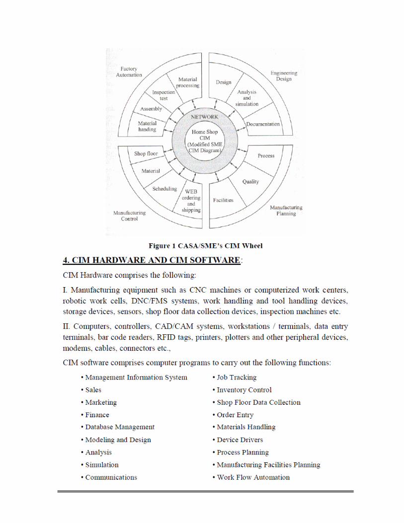
Explain the various segments of CIMS with the help of CIM wheel. (S-06,
W-06, S-07, W-09, S-10, W-10, W-11)
5) Explain the evolution of CIM. Discuss any one CIM software. (W-09, S-11)
6) Write a Short Note on:
a) Difference between Automation & CIMS (S-06, W-10, W-11)
7) What is concurrent Engineering? Explain in brief.


Tulsiramji Gaikwad Patil College of Engineering and Technology, Nagpur
Department of Mechanical Engineering
Computer Integrated Manufacturing
Unit –II
Introduction to Numerical Control of Machines
* Why NC machines?
1) Automation and mass production are associated with advancement in technology.
2) In today world of globalization and Industrialization cut throat compition increases for productivity, time
& quality to satisfy this all industries are going for automation.
3) Automation means special purpose automation m/cs, automatic transfer lines and material handling
robots etc. which are controlled by a digital electronics unit.
4) In conventional large variety of components and product manufactured by general purpose machine
tools & skilled operators who was responsible for many inputs to the machine for example reading
drawing, dimensions, material loading, unloading and inspection for quality.
5) Although the general purpose machines are very flexible but this flexibility on the cost of time,
productivity & quality.
6) As the degree of complexity of component increases the tolerances of time and productivity become
closer.
7) The process was totally dependent on operators, the mistakes on the part of operator due to in
attention and tiredness, result in production of defective components.
8) To over come these problems of job & batch production several improvements had been made in
conventional m/cs by reducing the manual control element
9) At the age of second world war the special purpose machine like copying machine had been evolved
for producing similar component in mass level. It is also called tracer machines, a model or template
called master was used to manufactured first then a tracer or stylus scans the model r template and
controls the motion of cutting tool by mean of servo motor, mechanism.
10) The main disadvantage of copying machine is time spent on producing the master, as master is made
without automation and it has to be produced to high degree of accuracy. Since this operation is very
time consuming.
11) After copying machine automated lathe machine had been evolved but this type of setup of the
required dimensions of the parts are established by micro switches and stoppers.
The disadvantage of this setup is to setting of the limit switches and stoppers for every new product.
12) So all these problems of automation of medium and small volume production have been overcome by
numerically controlled machine tools where the machining opera hens/processes are controlled with
the help of coded instructions given to the machine tools.
The simplest definition of numerical control (NC) given by Electronic industries Association (EIA) USA
is :
“A system in which the actions are controlled by direct in section of numerical data at some point. The
system must automatically interpret at least some portion of this data”.
13) This definition elaborated as machine tools controlled by means of a prepared programme, which
consists of blocks or series of numbers, alphabets or alpha numerics.
These codes define the required position of each machine slide, feed, cuttings speed & depth of cut.
In addition the codes are used to control other functions like codeant ON /OFF, tool change, etc. The
data for preparing the coded instructions, called part programming.

NC machines :
What is the concept of NC machines?
1) Combining control system with coded programmed and machine tools is formed Numerical controlled
machine tools (NC machines)
2) NC machines having variety of complexities & capabilities. Conventionally NC control units added to
machine tools which were used to control the position of work piece and relative motion of cutting tool.
But the operator was required to select the cutting tolls, speed & feeds etc.

3) But As time passes the capabilities of machines tools improved and in addition to maintaining cutting
tools & work piece relationship, the material removal was also controlled by the numerical control
system.
4) NC machines consisting of following types of components.
1) Program of instruction (paper tape or magnetic tape)
2) Machine control Unit.
3) Machine tool or processing equipment.
Diagram:
NC Machine System
1) Program of instruction: The instructions to NC machines are fed through an external medium i.e.
paper tape or magnetic tape. The information coded on the paper tape and magnetic tap inform of
coded punter with specific position. Which defines, cutting tool position with respect to the work piece.
2) Machines control Unit :- The information read through an external medium i.e., paper tap or
magnetic tape processed and decoded in for m of digital signals which converts these digital signals
into analog signals and control the motion of cutting tool with respect to work piece. This read
information stored into the memory of the control system called “buffer storage” and is processed by
the machine is working on one instructions block, the next block read from the tape and stored in the
memory of machine control system.
3) Machine tool or processing unit :- Since the part cannot be produced without a tape being run
through the control unit these type of NC machines called tape controlled machines. The machine
tool. reads the digital signals inform of analog and transmit inform of mechanical motion for producing
components. The tape has to be run repeatedly to be produced. Also if there is minor change inhering
of component, the tape has to be discarded and new tape with changed programme has to be
produced.

CNC Machines:
*What is the concept of CNC machines?
1) In case of computer is used to perform all basic NC functions to control the machine tolls this type of
machine tool system is called CNC machine (computer numerical controlled machine)
2) The complete part program to produce a component is input and stored in the computer memory and
the information for each operation is fed to the machine tools i.e. motors, etc.
3) The programs can be stored in memory of the computer and used in future.
Some of important features available for CNC m/c:-
1) The part program can be input to the controller unit through keyboard
2) The part program can be input to the computer memory can be used again and again.
3) The part program can be edited and optimized at m/c tool itself if there is any change in the design of
the component the part program can be changed according to the requirements.
4) The input information can be reproduced by developing sub program favor putative operations. For
example, for making holes on pitch circle etc. Subroutines can be retrieved and used any number of
times within a part program only certain parameters have to be specified.
5) The CNC machines have the facility for providing the part program without actually running it on the
machine tool. Each operation we can execute actual running of machine tool with we can see the
video of operation on monitor screen.
6) CNC control unit allows compensation for any changes the dimension of cutting tool. Because
according to part program particular type & size of cutting tool in mind. But in actual use that cutting
may not available. So in this regard CNC can provide compensation to made difference between the
programmed cutter and the actual cutter used.
7) CNC machines system, useful to the management also like control system can provide the
information such as number of components produced, time per component time for setting up a job,
time for which a particular toll has been use, time for which machine has not been working and fault
diagnosis etc.
CNC machine consist of following component;-
1) Program instruction
2) Machine control unit
3) Machine tool or processing equipment.
Diagram:-
CNC Machine system

1) Program instruction: The program of CNC machine in two type’s manual part programming & APT
manual part programming use in special coded instructions for different machining operat ion ‘G’ code
& ‘H’ code form. After the completion of part program it is allow to execute without actual operation
and check where her it is correct or not in control unit of CNC machine.
2) Machine Control Unit (MCU):- The machine control unit through which reading of the part
programming and convert these coded instruction to the main operation instruction in digital mode and
transmit the coded digital signal of instruction to the machine tool.
MCU also provides the actual working interface of the actual operation without machine tool running
which can be helpful to find out defects an part programming.
MCU work as a management unit of CNC machine tool for managing various operational activities
and store the information like program and sort of instruction for future use.
Direct Numerical control (DNC machine):-
What is the concept of DNC machines?
1) Direct Numerical control (DNC) machine is a new generation manufacturing system in which large
number of machines is controlled by a computer through the direct connections.
2) All machines linked to a main frame computer which sends information to individual machines when
required.
3) The part programming for all the components, which are to be manufactured on DNC system, are
stored in the memory of the computer.
4) There are two types of system configuration for linking the computer with machine tool.
The 1st configuration in which main computer is directly linked to the machine but in this type there
can be delay in communicating the instruction in between computers. 2nd configuration the main computer
is connected to machine tool through a minim computer called satellite computer. The main computer
stores the part programmes for all the components to be mechanical on a particular machine. The
satellite computer receives and stores the part program. The satellite computer controls the machines tool
operation. The advantage of this system is that the machine can be used independent of the main
computer as the main computer is not actively involved in operation of machine tool.
Advantage DNC machine that we can give the instruction of complier manufacturing unit from very
long distance.
There are various components of DNC machines as follows :-
1) Central main frame satellite computer with bulk memory.
2) Satellite minicomputer with memory buffer
3) Tele communication lines
4) Machine tolls.

Diagram:
1) Central Computer:- It is the master computer which consist or execute the part program and transmit
the command or instruction directly or through satellite to mini subsystem through the
telecommunication system.
The control computer consists of main Bulk memory for storing different part program and sort of
instruction.
2) Satellite mini computers:- Satellite mini computers are the sub systems which are linked to their
machine tool. There computer taking signals in form of instruction from the central computer directly
or through satellite these instruction transmit to the machine tool for operation. These computers
having. Buffer memory for storing the program and instruct.
3) Telecommunication lines:- Telecom.- communication lines through which the central mainframe
computer linked with satellite minicomputer directly or through satellite.
4) Machine tool:- Machine tools receives the digital signal from minicomputers inform of instruction and
convert that digital signals into the analog signals and perform different machining operations.
Advantages of CNC machines:
*What are the advantages of CNC M/C?
There are following advantages of CNC machine:-
1) Reducing Lead Time :- It is the time there receipt of a design drawing by production department and
manufacturer getting ready to start production including the time needed for planning, design or Jigs &
Fixtures etc. is called lead time.
Since special Jigs and fixtures are often entirely eliminated CNC machines, the whole of the time
needed for their design and manufacturing saved.
CNC machine can start production within a short period of the work being planned and material being
available.
2) Elimination of operator Errors: - The machine is controlled by program of instructions stored in
memory. The program is checked before goes on machine so no errors will occur in job Fatigue
boredom or in attention by a operator will not effect the quality or duration of the machining.
3) Operator Activity:- The operator is relieved of talks readily performed like pre-setting of tools, setting
of components and preparation of planning so man factor totally eliminated in CNC systems.
4) Lower Labour cost:- CNC machine requires lower operation time hence one operator can room two
or more machines or multiple parallel machines at a time resulting reduced of labour cost.
5) Smaller Batches:- In CNC machines pre-setting of tolls and work piece is minimum 80 we can
produce different design of product with smaller batches.

6) Longer tool Life :-Tools can be used at optimum speed and feed because this functions are controlled
by part program so we can get Longer tool life.
7) Elimination of special Jigs & Fixtures:- Special Jig & Fixtures are often not used on CNC and cost and
storage space required for it totally eliminated because CNC having all these facilities in built.
8) Flexibility in changes of component Design:- The modification or changes in component design can
be readily accommodated by re programming.
9) Reduced inspection:- The time spent on inspection and in waiting for inspection to being greatly
reduced. Normally it is required to inspect only 1st component in place of inspection in batch wise.
10) Less scrap:- Since the operator error eliminated results the proper planning of raw material use and
tool setting which avoids raw material & tools wastage. Which result into less scrap.
11) Accurate costing & scheduling:-In CNC machine the time fell in maching is predictable, consist and
result in greater accuracy of costing & scheduling and more predictable output.
Disadvantages of CNC machines
Explain various disadvantages of CNC m/c3
There are four main disadvantages of CNC m/c are as follows:-
1) Higher Investment Cost: - CNC machine tolls represent a more sophisticated and complex technology.
This technology costs more to buy than its non CNC counterpart, higher cost requires manufacturing
management, erection & operation.
2) Higher Maintenance Cost: - CNC machines are more sophisticated and complex then maintenance
problem occur more frequency and it required skilled manpower for maintenance which cost is very high.
3) Costlier CNC personnel:- Certain aspects of CNC machine operations requires a higher skill level than
conversional operations. Part program & CNC maintenance with required skill are in short supply. Hence cost
of CNC personnel hiring is very high.
4) Planned Support facility:- CNC operations is done which required a vast planned support facility for
different planning of work, time, cost & material which much costlier as compaire to conversional one.
Classification of CNC machines.
*What are different type of control system ?
Ans : I) Based on the motion type point to point, straight line & contouring system.
a) Point to Point control system :-
1) point to point control is one where accurate positional slides only to place the machine slides in fixed
position & the machine tool slide is required to reach a particular fixed to co-ordinate point in the shortest
possible time.
2) The machining operating are performed at specific points and there is no machining while the machine
table/slide move from one point to the next. No machining takes place until the machine slides have reached
the programmed co-ordinate point and slide movement ceases. Since there is no machining when the
machine slides move from one point to other point.
3) Here path of movement of tool is not important but care must be taken to ensure that the costing tool
should not hit the work piece while moving from one position to the next.
4) The movement along different axis may be sequential or simultaneous. The sequential or simultaneous
movement reducing machining time.
5) Point to point system is suitable for drilling, boring, tapping, punch presses and jig boring machines.

Diagram :
Point - to – point system
b) Straight line control system :-
1. It is extension of point to point control system in which special provision for maching along a straight
line as in case of milling, turning & facing.
2. In this control system controlled feed provides along the axis in line motion.
3. In this control system it is capable of calculating and displacing the slides simultaneously at suitable
feed rates to reach the desired points.
C) Continuous path or contouring control system
1. The contouring system is a high technology and most versatile control system. The control system
generates continuous motion of tool and work piece along different co-ordinate axis.
2. This system enables the machining of profile, contours and curved surfaces.
3. This system designed for continuous path machining hence in it we can perform point to point &
straight line machining also
4. In this system the machine tool, tool & work piece movement control simultaneously relative positions
and velocities at every point throughout the operation.
Diagram :
Contouring System

*Explain the open loop & close loop control system:
II) Based on Feedback control
a) Open-loop control System :
Diagram
Open loop control system
Block diagram of an open-loop system.
1) Machine toll control in which there is no provision to compare the actual position of cutting tool or work
piece are called open-loop systems.
2) Programmed instructions are fed into the controller through an input device. These instructions are
then convert to electrical pulses (signals) by the controller and sent to the servo amplifier to energize
the servo motors.
3) The primary drawback there is not monitoring of the actual displacement of the machine slide.
4) For these reasons the open-loop system is generally used in point-to-point systems. Where the
accuracy requirements are not critical.
5) In open –loop control system the actual displacement of the slide way vary with change in external
conditions and wear of components of the drive mechanism. Since there is no provision of feed back
in the control system periodical adjustment are required to compensate for the changed due to
various factors.

b) Closed –loop control system :
Diagram :
1) In a closed –loop control system i.e. actual displacement of the machine slide, is compared with the
input signal. The closed loop control systems are characterized by the presence of feed-back devices
in the system.
2) In the closed –loop control system the displacement can be achieved by a very high degree of
accuracy because a measuring or monitoring devices is used to determine the displacement of the
slide.
3) The feedback from the monitoring device is then compared with the input. Signal and slide position is
regulated by the servo system until it agrees with desired position a closed loop control system with a
provision for feed back for the displacement of position of machining slide. In order to measure the
speed of the motor and compare the actual speed with the programmed speed, a velocity feed backs
system is added to the system.

III) Based on the number of axes 2,3,4, & 5 axes CNC machines
1) 2 & 3 lathes will be coming under 2 axes machines. There will be two axes along which motion
takes place. The saddle will be moving


Q.5.Write a manual part program for machining the profile as shown in figure. Assume the depth of
slot to be 2 mm. Assume appropriate speed and feed. Take the billet size as 100 x 100 x 10 mm. Briefly
explain each program statement.
All dimensions are in mm.
Answer: ‐ Program
N001 G21 G92 X0 Y0 Z0;
N002 G00 X15 Y30;
N003 G01 X40 Y25 Z‐2 F40;
N004 G01 X60;
N005 G01 X85 Y30;
N006 G01 Y70;
N007 G01 X60 Y75;
N008 G01 X40;
N009 G01 X15 Y70;
N010 G01 Y30;
N011 G00 X0 Y0 Z0;
N012 G00 X40 Y25;
N013 G03 X60 Y25 R10; 27
N014 G00 X0 Y0 Z0;
N015 G00 X40 Y75;
N016 G02 X60 Y75 R10 F40;
N017 G00 X0 Y0 Z0;
N018 G00 X47.5 Y50;
N019 G02 X47.5 Y50 Z‐2 R2.5;
N020 M30;

Q.6.Write a manual part program to mill a slot as shown in figure.1 on an aluminum billet of size 100 x
100 x 10 mm. the depth of the slot should be 2 mm by using a drill bit of φ 5 mm. Assume suitable
machining data wherever necessary.
All dimensions are in mm.
Answer: ‐ Program
N001 G21 G92 X0 Y0 Z0;
N002 G00 X20 Y40;
N003 G01 X40 Y20 Z‐2 F40;
N004 G01 X20;
N005 G01 Y40;
N006 G01 X80;
N007 G01 Y60;
N008 G02 X60 Y80 R20;
N009 G01 X40; 28
N010 G03 X20 Y60 R20;
N011 G01 Y40;
N012 G00 X0 Y0 Z0;
N013 M30;

Tulsiramji Gaikwad Patil College of Engineering and Technology, Nagpur
Department of Mechanical Engineering
Computer Integrated Manufacturing
Unit –III
Group Technology
Introduction
As early as in the 1920ies it was observed, that using product-oriented departments to manufacture standardized
products in machine companies lead to reduced transportation. This can be considered the start of Group
Technology (GT). Parts are classified and parts with similar features are manufactured together with
standardized processes. As a consequence, small "focused factories" are being created as independent operating
units within large facilities.
More generally, Group Technology can be considered a theory of management based on the principle that
"similar things should be done similarly". In our context, "things" include product design, process planning,
fabrication, assembly, and production control. However, in a more general sense GT may be applied to all
activities, including administrative functions.
The principle of group technology is to divide the manufacturing facility into small groups or cells of machines.
The term cellular manufacturing is often used in this regard. Each of these cells is dedicated to a specified
family or set of part types. Typically, a cell is a small group of machines (as a rule of thumb not more than five).
An example would be a machining center with inspection and monitoring devices, tool and Part Storage, a robot
for part handling, and the associated control hardware.
The idea of GT can also be used to build larger groups, such as for instance, a department, possibly composed
of several automated cells or several manned machines of various types. As mentioned in Chapter 1 (see also
Figure 1.5) pure item flow lines are possible, if volumes are very large. If volumes are very small, and parts are
very different, a functional layout (job shop) is usually appropriate. In the intermediate case of medium-variety,
medium-volume environments, group configuration is most appropriate.
GT can produce considerable improvements where it is appropriate and the basic idea can be utilized in all
manufacturing environments:
To the manufacturing engineer GT can be viewed as a role model to obtain the advantages of flow line
systems in environments previously ruled by job shop layouts. The idea is to form groups and to aim at a
product-type layout within each group (for a family of parts). Whenever possible, new parts are
designed to be compatible with the processes and tooling of an existing part family. This way,
production experience is quickly obtained, and standard process plans and tooling can be developed for
this restricted part set.
To the design engineer the idea of GT can mean to standardize products and process plans. If a new part
should be designed, first retrieve the design for a similar, existing part. Maybe, the need for the new
part is eliminated if an existing part will suffice. If a new part is actually needed, the new plan can be
developed quickly by relying on decisions and documentation previously made for similar parts. Hence,
the resulting plan will match current manufacturing procedures and document preparation time is
reduced. The design engineer is freed to concentrate on optimal design.

In this GT context a typical approach would be the use of composite Part families. Consider e.g. the
parts family shown in Figure 3.1.
Figure 3.1. Composite Group Technology Part
(Askin & Standridge, 1993, p. 165).
The parameter values for the features of this
single part family have the same allowable
ranges. Each part in the family requires the
same set of machines and tools; in our
example: turning/lathing (Drehbank), internal
drilling (Bohrmaschine), face milling
(Planfräsen), etc.
Raw material should be reasonably consistent
(e.g. plastic and metallic parts require different
manufacturing operations and should not be in
the same family).
Fixtures can be designed that are capable of
supporting all the actual realizations of the
composite parts within the family.
Standard machine setups are often possible
with little or no changeover required between
the different parts within the family (same
material, same fixture method, similar size,
same tools/machines required).
In the functional process (job shop) layout, all parts travel through the entire shop. Scheduling and
material control are complicated. Job priorities are difficult to set, and large WIP inventories are used
to assure reasonable capacity utilisation. In GT, each part type flows only through its specific group
area. The reduced setup time allows faster adjustment to changing conditions.
Often, workers are cross-trained on all machines within the group and follow the job from Start to
finish. This usually leads to higher job satisfaction/motivation and higher efficiency.
For smaller-volume part families it may be necessary to include several such part families in a machine
group to justify machine utilization.
One can identify three different types group layout:
Figure 3.2a. GT flow line
(Askin & Standridge, 1993, p. 167).
In a GT flow line concept all parts
assigned to a group follow the same
machine sequence and require relatively
proportional time requirements on each
machine.
The GT flow line operates as a mixed-
product assembly line system; see Figure
3.2a. Automated transfer mechanisms
may be possible. See also Chapter 4 for
mixed-product assembly lines.

Figure 3.2b. GT cell
(Askin & Standridge, 1993, p. 167).
The classical GT cell allows parts to move from
any machine to any other machine. Flow is not
unidirectional. However, since machines are
located in close proximity short and fast transfer
is possible.
Figure 3.2c. GT center
(Askin & Standridge, 1993, p. 167).
The GT center may be appropriate when
large machines have already been located
and cannot be moved, or
product mix and part families are dynamic
and would require frequent relayout.
Then, machines may be located as in a process
layout by using functional departments (job
shops), but each machine is dedicated to
producing only certain Part families. This way,
only the tooling and control advantages of GT
can be achieved. Compared to a GT cell layout,
increased material handling is necessary.

GT offers numerous benefits w.r.t. throughput time, WIP inventory, materials handling, job
satisfaction, fixtures, setup time, space needs, quality, finished goods, and labor cost; read also
Chapter 6.1 of Askin & Standridge, 1993.
In general, GT simplifies and standardizes. The approach to simplify, standardize, and internalize
through repetition produces efficiency.
Since a workcenter will work only on a family of similar parts generic fixtures can be developed and
used. Tooling can be stored locally since parts will always be processed through the same machines.
Tool changes may be required due to tool wear only, not part changeovers (e.g. a press may have a
generic fixture that can hold all the parts in a family without any change or simply by changing a part-
specific insert secured by a single screw. Hence setup time is reduced, and tooling cost is reduced.
Using queuing theory (M/M/1 model) it is possible to show that if setup time is reduced, also the
throughput time for the system is reduced by the same percentage.
How to form groups
Askin & Standridge, 1993, Chapter 6.2 provides a list of seven characteristics of successful groups:
Characteristic Description
Team specified team of dedicated workers
Products specified set of products and no others
Facilities specified set of (mainly) dedicated machines equipment
Group layout dedicated contiguous space for specified facilities
Target common group goal, established at start of each period
Independence buffers between groups; groups can reach goals independently
Size Preferably 6-15 workers (small enough to act as a team with a
common goal; large enough to contain all necessary resources)
Clearly, also the organization should be structured around groups. Each group performs functions that
in many cases were previously attributed to different functional departments. For instance, in most
situations employee bonuses should be based on group performance.
Worker empowerment is an important aspect of manned cells. Exchanging ideas and work load is
necessary. Many groups are allocated the responsibility for individual work assignments. By cross-
training of technical skills, at least two workers can perform each task and all workers can perform
multiple tasks. Hence the there is some flexibility in work assignments.
The group should be an independent profit center in some sense. It should also retain the responsibility
for its performance and authority to affect that performance. The group is a single entity and must act
together to resolve problems.
There are three basic steps in group technology planning:
1. coding

2. classification
3. layout.
These will be discussed in separate subsections.
Coding schemes
The knowledge concerning the similarities between parts must be coded somehow. This will facilitate
determination and retrieval of similar parts. Often this involves the assignment of a symbolic or
numerical description to parts (part number) based on their design and manufacturing characteristics.
However, it may also simply mean listing the machines used by each part.
There are four major issues in the construction of a coding system:
part (component) population
code detail
code structure, and
(digital) representation.
Numerous codes exist, including Brisch-Birn, MULTICLASS, and KK-3. One of the most widely used
coding systems is OPITZ. Many firms customize existing coding systems to their specific needs.
Important aspects are
The code should be sufficiently flexible to handle future as well as current parts.
The scope of part types to be included must be known (e.g. are the parts rotational, prismatic,
sheet metal, etc.?)
To be useful, the code must discriminate between parts with different values for key attributes
(material, tolerances, required machines, etc.)
Code detail is crucial to the success of the coding project. Ideal is a short code that uniquely identifies
each part and fully describes the part from design and manufacturing viewpoints,
Too much detail results in cumbersome codes and the waste of resources in data collection.
With too few details and the code becomes useless.
As a general rule, all information necessary for grouping the part for manufacturing should be included
in the code whenever possible. Features like outside shape, end shape, internal shape, holes, and
dimensions are typically included in the coding scheme.
code structure, codes are generally classified as, hierarchical (also called monocode), chain (also
called polycode), or hybrid. This is explained in Figure 3.3 (taken from Askin & Standridge,
1993).
Hierarchical code structure: the meaning of a
digit in the code depends on the values of
preceding digits. The value of 3 in the third
place may indicate
the existence of internal threads in a
rotational part: "1232"
a smooth internal feature: "2132"
Hierarchical codes are efficient; they only
consider relevant information at each digit. But

Figure 3.3a. Hierarchical structure.
Figure 3.3b. Chain structure.
they are difficult to learn because of the large number of conditional inferences.
Chain code: each value for each digit of the code has a consistent meaning. The value 3 in the third place
has the same meaning for all parts.
They are easier to learn but less efficient. Certain digits may be almost meaningless for some parts.
Figure 3.3c. Chain structure.
Since both hierarchical and chain codes have
advantages, many commercial codes are
hybrid: combination of both:
Some section of the code is a chain code and
then several hierarchical digits further detail
the specified characteristics. Several such
sections may exist. One example of a hybrid
code is OPITZ.
The final decision is, code representation. The digits can be
numeric or even binary; for direct use in computer (storage and retrieval efficiency)
alphabetic; humans are more comfortable with a coding like "S" for smooth or "T" for thread
(Gewinde) than with digits
The proper decision process involves the design engineer, manufacturing engineer, and Computer
scientist working together as a team.
A well known coding system is OPITZ. It can have 3 sections:
it starts with a five-digit "geometric form code"
followed by a fourdigit "supplementary code."
This may be followed by a company-specific four-digit "secondary code" intended for
describing production operations and sequencing.

Figure 3.4. Overview of the Opitz code (Askin & Standridge, 1993, p. 167).
Digit 1: shows whether the
part is rotational and also
the basic dimension ratio
(length/diameter if
rotational, length/width if
nonrotational).
Digit 2: main external
shape; partly dependent on
digit 1.
Digit 3: main internal
shape.
Digit 4: machining require-
ments for plane surfaces.
Digit 5: auxiliary features
like additional holes, etc.
For more details on the
meaning of these digits see
Figure 6.6 in Askin &
Standridge, 1993.

Figure 3.4. Opitz code
for sample part (Askin &
Standridge, 1993, p. 167).
An example for a coded
Part is shown in Figure
3.5.
Correct code: 2 2 4 0 0

Part coding is helpful for design and group formation. But, the time and cost involved in collecting
data, determining part families, and rearranging facilities can be seen as the major disadvantage of GT.
For designing new facilities and product lines, this is not so problematic: Parts must be identified and
designed, and facilities must be constructed anyway. The extra effort to plan under a GT framework is
marginal, and the framework facilitates standardization and operation thereafter. Hence, GT is a logical
approach to product and facility planning.
Classification (group formation)
Here, part codes and other information are used to assign parts to families. Part families are assigned to
groups along with the machines required to produce the parts. A variety of models for forming part-
machine groups are available in the literature, as can be seen from the following figure:
Figure 3.5. Methods of group formation

Production Flow Analysis (PFA)
Method of grouping part into families
Used to analyze the operation steps and machine routes for the parts produced groups parts
with similar or identical routings together
These groups can be used to form logical machine cells in a gt layout
Uses manufacturing data rather than design data to make groups, so takes care of the
problem of:
Parts whose basic geometry may differ but might take same or similar process routes
Parts whose basic geometry may be same or similar but require different process routings
Disadvantage:
Takes the route details the way they are, no check for optimal, consistent or logical routing
Production Flow Analysis: Procedure
1 Data Collection
Define the population of the parts to be analyzed
Study a sample or the whole population
Minimum data needed is the part number and routing sequence of each part (route sheets)
additional data as lot size, annual production rate, can be used to design cells of the desired
productivity
2 Sorting of Process
Routings
Arrange the parts according to the similarity of their process routings
Sorting procedure is used to arrange the parts into “packs”
“pack: is a group of parts with identical process routings
each pack is given a pack identification number or letter
3 PFA Chart
Processes used for each pack are displayed graphically on a PFA chart
Plot of the process code numbers for all the packs that have been determined
4 Analysis
Most difficult and crucial step
From the PFA chart, similar groups are identified
Minimum data needed is the part number and routing sequence of each part (route sheets)
Additional data as lot size, annual production rate, can be used to design cells of the desired
Productivity

Example (Matrix Form)
Production Flow Analysis: Procedure
1) There will be packs that do not fit into similar groupings
2) These parts can be analyzed to determine if a revised process sequence can be developed which fits
to one of the groups
3) If not possible, then these parts continue to be manufactured through a conventional process
4) Type plant layout
5) weakness of PFA is that the data used in the analysis is derived from route sheets, prepared by
different process planners
6) Routings may contain unnecessary and non-optimal steps
7) Final groupings may be sub-optimal
8) Requires less time to perform than a complete parts classification and coding
Procedure
Group Technology: Machine Cell Design Composite Part Concept
• A Composite Part for a given family, which includes all of the design and manufacturing attributes of
the family
• An individual part in the family will have some of the features that characterize the family but not all
of them
• Composite part possesses all of the features

Machine Cell Designs: Types Term “cellular manufacturing” is used to describe the operations of a GT machine cell _ can be classified,
based on number of machines and the degree to which the material f low is mechanized between the
machines:
1. single machine cell
2. group machine cell with manual handling
3. group machine cell with semi-integrated handling
4. flexible manufacturing system (FMS)
Machine Cell Designs: Type 1
Single machine cell
1. It consists of 1 machine plus supporting fixtures and tooling to make one or more part families
2. It can be applied to work parts that is made by one type of process, such as turning or milling
Machine Cell Designs: Type 2 Group machine cell with manual handling using a U-shaped layout
1. It consists of more than one machine used collectively to make one or more part families
2. There no provision for mechanized part movement between machines
3. Human operators running cell, perform material handling; if size of the part is huge or arrangement of
machines in cell is large, regular handling crew may be required
4. It may organized in a U-shape layout when there is variation in work f low in parts; also useful in
movement of multi functional workers
5. Design is often achieved without rearranging the process-type layout; simply include certain machines
in group and restrict their work to specified part family
6. Saves cost of rearranging but many material handling benefits of GT are not realized

Machine Cell Designs: Type 3 Group machine cell with semi-integrated handling
1. Uses a mechanized handling system, such as a conveyor, to move parts between machines in
the cell
2. Parts made in the cell have identical or similar routing – in-line layout (a)
3. Machines are laid along a conveyor to match the processing sequence
4. P routings vary in parts – loop layout (b)
5. Allows parts to circulate in the handling system
6. Permits different processing steps in the different parts in the system
Machine Cell Designs: Type 4
Flexible Manufacturing System (FMS)
1. highly automated machine cells in GT
2. combines automated processing stations with a fully integrated material handling system
Best Machine Arrangement Depends on the work processing requirements important factors are:
1. Volume of the work to be done by the cell includes the number of parts per year and the work required
per part
2. Influences number of machines to be used in cell, cost of operating a cell, amount of money
to be spent in establishing a cell
• Variations in process routings of the part determines the work flow; for identical routings- in-line flow,
significant variation in routing – a U-shape or loop layout
• Part size, shape, weight, and other physical attributes determine the size and type of material handling and
processing equipment that can be used

Opitz Classification System One of the first published and best known classification and coding schemes for mechanical parts
uses the following digit sequence
12345 6789 ABCD
1. basic code consists of 9 digits
2. digits 1 through 5 (12345) -> form code
3. primary shape and design attributes (hierarchical structure)
4. digits 6 through 9 -> supplementary code – attributes that are useful in manufacturing (e.g.,
dimensions, starting material)
5. digits 10 through 13 (ABCD) ->secondary code – identify production operation type and sequence
very complex system
Benefits of Group Technology
1. Product design
Derived from coding and classification
If new part design is required -> code of the required part is figured out matched with the existing
part designs
Design standardization
2. Material handling is reduced
parts are moved within a machine cell rather than the entire factory
3. Process planning and production scheduling are simplified
4. Work-in-process and manufacturing lead time are reduced
5. Improved worker satisfaction in a GT cell
6. Higher quality work

Tulsiramji Gaikwad Patil College of Engineering and Technology, Nagpur
Department of Mechanical Engineering
Computer Integrated Manufacturing
UNIT-IV
Introduction To Flexible Manufacturing System
Manufacturing Industries are facing vigorous threats by inflation in market needs, corporate
lifestyle and globalization. Hence, in current situation, Industries which are responding rapidly to
market fluctuations with more competitiveness will have great capabilities in producing
products with high quality and low cost. In the view of manufacturers, production cost is not at
all a significant factor which affects them. But, some of the factors which are important to the
manufacturer are flexibility, quality, efficient delivery and customer satisfaction.
Hence, with the help of automation, robotics and other innovative concepts such as just-in-time
(JIT), Production planning and control (PPC), enterprise resource planning (ERP) etc.,
manufacturers are very keen to attain these factors.
Flexible manufacturing is a theory which permits production systems to perform under high
modified production needs. The problems such as minimum inventories and market-response
time to bump into customer needs, response to adjust as per the deviations in the market. In order
to sweep market by reducing the cost of products and services will be mandatory to various
companies to shift over to flexible manufacturing systems. FMSs as a possible way to overcome
the said issues while making reliable and good quality and cost effective yields. Flexible
manufacturing system has advanced as a tool to bridge the gap between high mechanized line
and CNC Machines with efficient mid- volume production of a various part mix with low setup
time, low work- in-process, low inventory, short manufacturing lead time, high machine
utilization and high quality FMS is especially attractive for medium and low-capacity industries
such as automotive, aeronautical, steel and electronics.
Flexible manufacturing system incorporates the following concepts and skills in
an automated production system
1. Flexible automation
2. Group technology
3. Computer numerical control machine tools
4. Automated material handling between machines

TYPES OF FMS
Flexible manufacturing systems can be separated into various types subject to their natures:
1. DEPENDING UPON KINDS OF OPERATION
Flexible manufacturing system can be illustrious subject to the kinds of operation
performed:
a. Processing operation.
It performs some activities on a given job. Such activities convertthe job
from one shape to another continuous up to the final product. It enhances
significance by altering the geometry, features or appearance of
the initial materials.
b. Assembly operation. It comprises an assembly of two or more parts to make a
new component which is called an assembly/subassembly. The subassemblies which
are joined permanently use processes like welding, brazing, soldering , adhesive
bonding, rivets, press fitting.
2. BASED ON NUMBER OF MACHINES
There are typical varieties of FMS based on the number of machines in the system:
a. Single machine cell (SMC). It consists of completely automated machines which
are capable of performing unattended operations within a time period lengthier than one
complete machine cycle. It is skilful of dispensing various part mix, reacting to
fluctuations in manufacture plan, and inviting introduction of a part as a new entry. It is a
sequence dependent production system.
b. Flexible manufacturing cell (FMC). It entails two or three dispensing
workstations and a material handling system. The material handling system is linked to a
load/unload station. It is a simultaneous production system.

c. An Flexible Manufacturing System (FMS). It has four or more
processing work stations (typically CNC machining centers or turning centers)
connected mechanically by a common part handling system and automatically by
a distributed computer system. It also includes non-processing work stations that
support production but do not directly participate in it e.g., part / pallet washing
stations, co-ordinate measuring machines. These features significantly
differentiate it from Flexible manufacturing cell (FMC).
Comparison for three categories of FMS
In this research, authors focused on Flexible manufacturing system
3. BASED ON LEVEL OF FLEXIBILITY
FMS is further classified based on the level of flexibility related to the manufacturing system.
Two categories are depicted here:
a. Dedicated FMS. It is made to produce a certain variety of part styles. The product
design is considered fixed. So, the system can be designed with a certain amount of
process specialization to make the operation more efficient.
Flexible manufacturing System
Flexible manufacturing cell
Single machine cell
Num
ber
of m
ach
ines
(M)

b. Random order FMS. It is able to handle the substantial variations in part
configurations. To accommodate these variations, a random order FMS must
be more flexible than the dedicated FMS. A random order FMS is capable of
processing parts that have a higher degree of complexity. Thus, to deal with
these kinds of complexity, sophisticated computer control system is used for
this FMS type.
In this research, authors consider Random order FMS
Production rate(Z), annual volume(V)
Differences between dedicated and random-order FMS types
Flexibility is an attribute that allows a mixed model manufacturing system
to cope up with a certain level of variations in part or product style, without
having any interruption in production due to changeovers between models.
Flexibility measures the ability to adapt “to a wide range of possible
environment”. To be flexible, a manufacturing system must posses the
following capabilities:
Identification of the different production units to perform the correct operation
Quick changeover of operating instructions to the computer
controlled production machines
Quick changeover of physical setups of fixtures, tools and other working units
Random order of FMS
Dedicated FMS
Fle
xibilit
y(F
) , part
vari
ety
(p)

The different types of flexibility that are exhibited by manufacturing systems are given below:
1. Machine Flexibility. It is the capability to adapt a given machine in the system to a wide range of
production operations and part styles. The greater the range of operations and part styles the greater
will be the machine flexibility. The various factors on which machine flexibility depends are:
• Setup or changeover time
• Ease with which part-programs can be downloaded to machines
• Tool storage capacity of machines
• Skill and versatility of workers in the systems
2. Production Flexibility. It is the range of part styles that can be produced on the systems. The range
of part styles that can be produced by a manufacturing system at moderate cost and time is
determined by the process envelope. It depends on following factors:
• Machine flexibility of individual stations
• Range of machine flexibilities of all stations in the system
3. Mix Flexibility. It is defined as the ability to change the product mix while maintaining the same
total production quantity that is, producing the same parts only in different proportions. It is also
known as process flexibility. Mix flexibility provides protection against market variability by
accommodating changes in product mix due to the use of shared resources. However, high mix
variations may result in requirements for a greater number of tools, fixtures, and other resources.
Mixed flexibility depends on factors such as:
• Similarity of parts in the mix
• Machine flexibility
• Relative work content times of parts produced
4. Product Flexibility. It refers to ability to change over to a new set of products economically and
quickly in response to the changing market requirements. The change over time includes the time for
designing, planning, tooling, and fixturing of new products introduced in the manufacturing line-up.
It depends upon following factors:
• Relatedness of new part design with the existing part family
• Off-line part program preparation
• Machine flexibility
5. Routing Flexibility. It can define as capacity to produce parts on alternative workstation in case of
equipment breakdowns, tool failure, and other interruptions at any particular station. It helps in
increasing throughput, in the presence of external changes such as product mix, engineering changes,
or new product introductions. Following are the factors which decide routing flexibility:
• Similarity of parts in the mix

• Similarity of workstations
• Common tooling
6. Volume Flexibility. It is the ability of the system to vary the production volumes of different
products to accommodate changes in demand while remaining profitable. It can also be termed as
capacity flexibility. Factors affecting the volume flexibility are:
• Level of manual labor performing production
• Amount invested in capital equipment
7. Expansion Flexibility. It is defined as the ease with which the system can be expanded to foster
total production volume. Expansion flexibility depends on following factors:
• Cost incurred in adding new workstations and trained workers
• Easiness in expansion of layout
• Type of part handling system used
As indicated in our definition, there are several basic components of an FMS. In the following segment, a
framework for understanding the components of an FMS is presented. A flexible manufacturing
system consists of two subsystems:
Physical subsystem
Control subsystem
Physical subsystem includes the following elements:
1. Workstations. It consists of NC machines, machine-tools, inspection equipments, loading and
unloading operation, and machining area.
2. Storage-retrieval systems. It acts as a buffer during WIP (work-in-processes) and holds devices such
as carousels used to store parts temporarily between work stations or operations.
3. Material handling systems. It consists of power vehicles, conveyers, automated guided vehicles
(AGVs), and other systems to carry parts between workstations.
Control subsystem comprises of following elements:
1. Control hardware. It consists of mini and micro computers, programmable logic controllers,
communication networks, switching devices and others peripheral devices such as printers and mass
storage memory equipments to enhance the working capability of the FMS systems.
2. Control software. It is a set of files and programs that are used to control the physical subsystems.
The efficiency of FMS totally depends upon the compatibility of control hardware and control
software.

Basic features of the physical components of an FMS are discussed below:
1. Numerical control machine tools.
Machine tools are considered to be the major building blocks of an FMS as they determine the
degree of flexibility and capabilities of the FMS. Some of the features of machine tools are
described below;
The majority of FMSs use horizontal and vertical spindle machines. However, machining centers
with vertical spindle machines have lesser flexibility than horizontal machining centers.
Machining centers have numerical control on movements made in all directions e.g. spindle
movement in x, y, and z directions, rotation of tables, tilting of table etc to ensure the high
flexibility.
The machining centers are able to perform a wide variety of operations
e.g. turning, drilling, contouring etc. They consist of the pallet exchangers
2. Work holding and tooling considerations.
It includes pallets/fixtures, tool changers, tool identification systems, coolant, and chip removal systems. It
has the following features:
Before machining is started on the parts, they are mounted on fixtures. So, fixtures must be
designed in a way, to minimize part-handling time. Modular fixturing has come up as an attractive
method to fixture a variety of parts quickly.
The use of automated storage and retrieval system (AS/RS) and material handling systems such as
AGVs, lead to high usage of fixtures.
All the machining centers are well equipped with tool storage systems called tool magazines.
Duplication of the most often used tools in the tool magazines is allowed to ensure the least non-
operational time. Moreover, employment of quick tool changers, tool regrinders and provision of
spares also help for the same.
3. Material-Handling Equipments
The material-handling equipments used in flexible manufacturing systems include robots, conveyers,
automated guided vehicle systems, monorails and other rail guided vehicles, and other specially
designed vehicles. There important features are:
They are integrated with the machine centers and the storage and retrieval systems.
For prismatic part material handling systems are accompanied with modular pallet fixtures. For
rotational parts industrial robots are used to load/unload the turning machine and to move parts
between stations.

The handling system must be capable of being controlled directly by the computer system to direct it
the various work station, load/unload stations and storage area.
4. Inspection equipment
It includes coordinate measuring machines (CMMs) used for offline inspection and programmed to
measure dimensions, concentricity, perpendicularity, and flatness of surfaces. The distinguishing
feature of this equipment is that it is well integrated with the machining centers.
5. Other components
It includes a central coolant and efficient chip separation system. Their features are:
The system must be capable of recovering the coolant.
The combination of parts, fixtures, and pallets must be cleaned properly to remove dirt and chips
before operation and inspection.
HARDWARE COMPONENTS OF FLEXIBLE MANUFACTURING SYSTEM
1. Pallets and fixtures
2. Machining centers
3. Robots
4. Inspection equipment
5. Chip removal system
6. In process storage facility
7. Material handling systems
Flexible manufacturing system layouts
Flexible manufacturing system has different layouts according to arrangement of machine and
flow of parts. According to part flow and arrangement of machine, layout of flexible
manufacturing system are discussed below

In-line FMS layout
The machines and handling system are arranged in a straight line. In Figure 1(a) parts progress
from one workstation to the next in a well-defined sequence with work always moves in one
direction and with no back-flow. Similar operation to a transfer line except the system holds a
greater variety of parts. Routing flexibility can be increased by installing a linear transfer system
with bi-directional flow, as shown in Figure 1(b). Here a secondary handling system is provided
at each workstation to separate most of the parts from the primary line. Material handling
equipment used: in-line transfer system; conveyor system; or rail-guided vehicle system.
Loop FMS layout
Workstations are organized in a loop that is served by a looped parts handling system. In Figure
2, parts usually flow in one direction around the loop with the capability to stop and be
transferred to any station.
Figure 2: Loop FMS layout Each station has secondary handling equipment so that part can be
brought-to and transferred from the station work head to the material handling loop. Load/unload
stations are usually located at one end of the loop.

Rectangular FMS layout
This arrangement allows for the return of pallets to the starting position in a straight line
arrangement
Ladder FMS layout
This consists of a loop with rungs upon which workstations are located. The rungs increase the
number of possible ways of getting from one machine to the next, and obviate the need for a
secondary material handling system. It reduces average travel distance and minimizes congestion
in the handling system, thereby reducing transport time between stations. See Figure 4.

Open field FMS layout
It consists of multiple loops and ladders, and may include sidings also. This layout is generally
used to process a large family of parts, although the number of different machine types may be
limited, and parts are usually routed to different workstations depending on which one becomes
available first. See Figure 5.
Robot centered FMS layout
This layout uses one or more robots as the material handling system. See figure 6

FLEXIBLE MANUFACTURING SYSTEM
Factors Influencing the FMS Layouts
The various factors influencing the layouts of FMS are:
1. Availability of raw material
2. Proximity to market
3. Transport facilities
4. Availability of efficient and cheap labor
5. Availability of power, water and fuel
6. Atmospheric and climatic condition
7. Social and recreation facilities
8. Business and economic conditions
Sequencing of jobs
The machines are arranged in a typical layout in a given FMS environment. The set of jobs are
processed, those have different operations. According to their processing time, due dates these
jobs scheduled to minimize make span. There are following rules selected from many existing
priority scheduling rules to obtain optimum sequence.
First-Come, First-Serve (FCFS) - the job which arrives first, enters service first (local rule). It
is simple, fast, “fair” to the customer. And disadvantage of this rule is, it is least effective as
measured by traditional performance measures as a long job makes others wait resulting in idle
downstream resources and it ignores job due date and work remaining (downstream
information).
Shortest Processing Time (SPT) - the job which has the smallest operation time enters service
first (local rule). Advantages of this sequencing rule is simple, fast, generally a superior rule in
terms of minimizing completion time through the system, minimizing the average number of
jobs in the system, usually lower in-process inventories (less shop congestion) and downstream
idle time (higher resource utilization), and usually lower average job tardiness and disadvantages
is, it ignores downstream, due date information, and long jobs wait (high job wait-time
variance).
Earliest Due Date (EDD) - the job which has the nearest due date, enters service first (local
rule) and it is simple, fast, generally performs well with regards to due date, but if not, it is
because the rule does not consider the job process time. It has high priority of past due job and it
ignores work content remaining.

Critical Ratio (CR) Rule - sequences jobs by the time remaining until due date divided by the
total remaining processing time (global rule). The job with the smallest ratio of due date to
processing time enters service first. The ratio is formed as (Due Date-Present Time)/Remaining
Shop Time where remaining shop time refers to: queue, set-up, run, wait, and move times at
current and downstream work centers. it recognizes job due date and work remaining
(incorporates downstream information)but in this sequencing, past due jobs have high priority,
does not consider the number of remaining operations
Slack Per Operation - is a global rule, where job priority determined as (Slack of remaining
operations) it recognizes job due date and work remaining (incorporates downstream
information) Least Changeover Cost (Next Best rule) - sequences jobs by set-up cost or time
(local rule).it is simple, fast, generally performs well with regards to set-up costs. it does not
consider the job process time, due date and work remaining.
FMS- Components
Components/Elements of FMS
As pointed out in the definition four basic components/elements of a FMS are
i) Workstations
ii)Material handling and storage system
iii) Computer control system
iv) Human resources
1) FMS Workstations
The workstations/processing stations used in FMS depend upon the type of product
manufactured by the system. In metal cutting/machining systems, the principle processing
stations are usually CNC machine tools. In addition, a FMS requires other several machines for
Completing the manufacturing
The types of workstations that are usually found in a FMS are
i) Load/unload stations
ii)Machining stations
iii)Assembly workstations
iv)Inspection stations
v)Other processing stations

2) Material Handling and Storage System
Material handling and storage system is the second main component of an FMS
Requirements set against the FMS material handling and storage system include part
transportation, raw material and final product transportation and storage of work pieces,
empty pallets, auxiliary materials, wastes, fixtures and tools
Functions of the material handling system
Random, independent movement of work parts between stations. This means that the
material handling system should be capable of moving work parts from one workstation
to any other station. This provides various routing alternatives for the different parts
Handle a variety of work part configurations. The material handling system should be
capable of handling any work part configurations, (prismatic or rotational parts)
Temporary storage. The material handling should be capable of storing the work parts
temporarily, so as to wait in a small queue at workstations. This helps to increase
machine utilization.
Convenient access for loading and unloading work parts. The material handling system
should provide a means to load and unload parts from the FMS. This can be achieved
by locating one or more loading and/or unloading stations in the system.
Compatible with computer control. Last but not the least, the material handling system
should be capable of being controlled by the computer to direct it to the various
workstations, load/unload stations and storage areas.
Types of Material Handling Equipment
The material handling function in a FMS is shared between two systems:
i) Primary handling system
ii) Secondary handling system.
i) Primary Handling System
•It establishes the basic layout of the FMS and is responsible for moving work parts
between workstations in the system.
•Table given below summarizes the type of material handling equipment typically
used as the primary handling system for the five FMS layouts.

ii)Secondary Handling System
•It consists of transfer devices, automatic pallet changers, and similar mechanisms
located at the workstations in the FMS.The functions of the secondary handling systems
are
i) To transfer work parts from the primary system to the machine tool or other
processing station
ii) To position the work parts with sufficient accuracy and repeatability at the
workstation for processing
iii) To provide buffer storage of work parts at each workstation, if required
iv) To reorient the work parts, if necessary, to present the surface that is to be processed.
Economics of FMS
i)5–20% reduction in personnel.
ii)15–30% reduction in engineering design cost
iii)30–60% reduction in overall lead time
iv)30–60% reduction in work-in-process
v)40–70% gain in overall production
vi)200–300% gain in capital equipment operating time
(vii)200–500% gain in product quality
viii)300–500% gain in engineering productivity.
Advantages of FMS
Successfully implemented FMS offer several advantages. Some of them are given
below:
1. Increased machine utilization - Several features of FMS (such as automatic tool/pallet
changing, dynamic scheduling of production and so on).
2. Reduced inventory -Following the GT concept, FMS processes different parts
together. This tends to reduce the work-in-process inventory significantly
3. Reduced manufacturing lead time - Because of reduced setups and more efficient
materials handling, manufacturing lead times are reduced
4. Greater flexibility in production scheduling - A FMS has a greater responsiveness
to change. It means, FMS has the capability to make adjustments in the production
schedule on day-to-day basis to respond to immediate orders and special customer
requests.

5.Reduced direct labour cost -Reduced (manual) material handling and automation
control of machines make it possible to operate an FMS with less direct labour in many
instances. Thus the direct labour cost is reduced considerably.
6.Increased labour productivity - Due to higher production rates and reduced direct
labour cost, FMS achieves greater productivity per labour hour.
7.Shorter response time - Setup time is relatively low with FMS as majority of the work
is done automatically. The lead time of production is hence very low and the response
time will be shorter.
8.Consistent quality - Human error is minimized, as there is maximum automation.
In the absence of human interface, the quality is consistent.
9.Other FMS benefits include
i) Reduced factory floor space
ii) Reduced number of tools and machines required
iii) Improved product quality
iv) Easy expandability for additional processes or added capacity
Disadvantages of FMS
The major limitations of implementing a FMS are given below
(i)Very high capital investment is required to implement a FMS
(ii)Acquiring, training and maintaining the knowledgeable labour pool requires heavy
investment
(iii)Fixtures can sometimes cost much more with FMS and software development costs
could be as much as 12–20% of the total expense.
(iv)Tool performance and condition monitoring can also be expensive since tool variety
could undermine efficiency.
v)Complex design estimating methodology requires optimizing the degree of flexibility
and finding a trade-off between flexibility and specialization.

Tulsiramji Gaikwad Patil College of Engineering and Technology, Nagpur
Department of Mechanical Engineering
Computer Integrated Manufacturing
UNIT-V & VII
Process Planning
•Product design for each product has been developed in the design department.
•To convert the product design into a product, a manufacturing plan is required. Activity of
developing such a plan is called process planning.
•Process planning consists of preparing sets of instructions that describe how to manufacture the
product and its parts.
•The task of process planning consists of determining the manufacturing operations required
to transform a part from a rough (raw material) to the finished state specified on the
engineering drawing. Also known as operations planning
•It is the systematic determination of the engineering processes and systems to manufacture a
product competitively and economically.
•It is a detailed specification which lists the operations, tools and facilities.
It is usually accomplished in manufacturing department.
Process Planning Definition
It can be defined as “an act of preparing a detailed processing documentation for the
manufacture of a piece part or assembly.” According to the American Society of Tool
and Manufacturing Engineers.
Process planning is the systematic determination of the methods by which a product
is to be manufactured economically and competitively.
It consists of devising, selecting and specifying processes, machine tools and other
equipment, transform the raw material into finished product as per the specifications
called for by the drawings.

Process Planning Vs Product Planning
Process planning
It is concerned with the engineering and technological issues of how to make the product
and its parts.
It specifies types of equipment and tooling required to fabricate the parts and assemble
the product.
Production planning
It is concerned with the logistics issues of making the product.
It is concerned with ordering the materials and obtaining the resources required to make
the product in sufficient quantities to satisfy demand for it.
Production is done only after the process planning.
Importance of Process Planning
Process planning establishes the link between engineering design and shop floor
manufacturing.
It determines how a part/product will be manufactured, the important determinant of
production costs and profitability.
Production process plans should be based on in-depth knowledge of process and
equipment capabilities, tooling availability, material processing characteristics, related
costs and shop practices.
Economic future of the industry demands that process plans that are developed should be
feasible low cost and consistent with plans for similar parts.
Process planning facilitates the feedback from the shop floor to design engineering
regarding the manufacturing ability of alternative.
Detailed process plan usually contains the route, processes, process parameters and
machine and tool selections.
To prepare a process plan (also called as route. sheet), we require the following information:
1. Assembly and component drawings and bill of materials (part list):
This detail gives the information regarding the general description of part to be manufactured,
raw material specification, dimensions and tolerances required, the surface finish and treatment
required.

2. Machine and equipment details:
(i)The various possible operations that can be performed.
(ii) The maximum and minimum dimensions that can be machined on the machines.
(iii) The accuracy of the dimensions that can be obtained.
(iv)Available feeds and speeds on the machine.
3. Standard time for each operation and details of setup time for each job
4. Availability of machines, equipment and tools
Process Planning Activities
The different steps or specific activities involved in process planning are:
Analysis of the finished part requirements as specified in the engineering design
Determining the sequence of operations required
Selecting the proper equipment to accomplish the required operations
Calculating the specific operation setup times and cycle times on each machine
Documenting the established process plans
Communicating the manufacturing knowledge to the shop floor.

The above process planning activities are diagrammatically presented in figure.
Computer Aided Process Planning (CAPP)
To overcome the drawbacks of manual process planning, the computer- aided process
planning
(CAPP) is used. With the use of computers in the process planning, one can reduce the
routine clerical work of manufacturing engineers.
It provides the opportunity to generate, rational consistent and optimal plans. In addition
CAPP provides the interface between CAD and CAM.
Benefits of CAPP
The benefits of implementing CAPP include the following:
Process rationalization and standardization: CAPP leads to more logical and
consistent process plans than manual process planning.
Productivity improvement: As a result of standard process plan, the productivity is
improved.
Product cost reduction: Standard plans tend to result in lower manufacturing costs and
higher product quality.

Elimination of human error.
Reduction in time: As a result of computerized work, a job that used to take several
days, is now done in a few minutes.
Reduced clerical effort and paper work
Improved legibility: Computer-prepared route sheets are neater and easier to read than
manually prepared route sheets.
Faster response to engineering changes: Since the logic is stored in the memory of the
Computer, CAPP becomes more responsive to any changes in the production parameters
than the manual method of process planning.
Incorporation of other application programs: The CAPP program can be interfaced with
Other application programs such as cost estimating and work standards.
Approaches of CAPP
The two basic approaches or types of CAPP system are:
1. Retrieval (or variant) CAPP system.
2. Generative CAPP system.
A CAPP tool can be represented as having three separate functions:
(i) Retrieval
(ii) Technological analysis
(iii) Computational

CAPP System for Engineering Data
Retrieval (or Variant) CAPP System
It is also called a variant CAPP system and has been widely used in machining
applications.
Basic idea behind the retrieval CAPP is that similar parts will have similar process plans.
A process plan for a new part is created by recalling, identifying and retrieving an
existing plan for a similar part and making the necessary modifications for the new part
Variant CAPP is a computer-assisted extension of the manual approach.
Advantages of Retrieval CAPP System
Once a standard plan has been written, a variety of parts can be planned.
Comparatively simple programming and installation (compared with generative CAPP
systems) is required to implement a planning system
Efficient processing and evaluation of complicated activities and decisions, thus reducing
the time and labour requirements.
Standardized procedures by structuring manufacturing knowledge of the process planners
to company’s needs.
Lower development and hardware costs.
Shorter development times.
The system is understandable and the planner has control of the final plan.
It is easy to learn and easy to use.

Disadvantages of Retrieval CAPP System
The components to be planned are limited to similar components previously planned.
Maintaining consistency in editing is difficult.
Experienced process planners are still required to modify the standard plan for the
specific component.
Components of a Generative CAPP System
The various components of a generative system are:
A part description, which identifies a series of component characteristics, including
geometric features, dimensions, tolerances and surface condition.
A subsystem to define the machining parameters, for example using look-up tables and
analytical results for cutting parameters.
A database of available machines and tooling.
A report generator which prepares the process plan report.
Structure of a Generative CAPP System

Advantages of Generative CAPP System
The generative CAPP has the following advantages:
It can generate consistent process plans rapidly.
New components can be planned as easily as existing components.
It has potential for integrating with an automated manufacturing facility to provide
detailed control information
Drawbacks of Generative CAPP System
The generative approach is complex.
It is very difficult to develop.
CMPP Process Planning Functions
The CMPP system can perform the following four processes planning functions:
CMPP generates a sequence of operations in a summary format.
The summary format contains for each operation an operation, number and description,
type of machine orientation of the work piece on the machine, surfaces cut and heat
treatment.
CMPP determines the dimensioning reference surfaces for each cut in each operation.
CMPP selects the clamping and locating surfaces.
CMPP determines machining dimensions, tolerances and stock removals for each surface
cut in each operation
CMPP Process Planning Functions
CMPP produces three process plan documents:
(i) A printed summary of operations.
(ii) A printed tolerance analysis
(iii) Dimensional work piece sketches for each machining operation.
CMPP Process Planning Functions
Even though the CMPP system has received limited use in the industrial environment, the CMPP
system is considered very significant because of the following three reasons:
(i) CMPP represents one of the most successful attempts at developing a generative system.
(ii) CMPP achieves a higher degree of automated process planning.
(iii) CMPP is being used as a basis for further search into automated process planning.

Selection of a CAPP System
Evaluation and selection of the best process planning system for a particular firm
involves numerous engineering management decisions.
Process involves identifying, weighing and comparing various interrelated factors.
Logical Steps in Computer Aided Process Planning
Step 1: Define the coding scheme
Adopt existing coding or classification schemes to label parts for the purpose of classification.
In some extreme cases, a new coding scheme may be developed.
Step 2: Group the parts into part families
Group the part families using the coding scheme defined in Step 1 based on some
common
part features.A standard process plan is attached to each part family (see: Step 3).
Often, a number of part types are associated with a family, thereby reducing the total
number of standard process plans
Step 3: Develop a standard process plan
Develop a standard process plan for each part family based on the common features of
the part types.
This process plan can be used for every part type within the family with suitable
modifications.
Step 4: Retrieve and modify the standard plan
When a new part enters the system, it is assigned to a part family based on the coding and
classification scheme.
Then the corresponding standard process plan is retrieved and modified to accommodate
the unique features of the new part

Retrieval CAPP System Procedure
Aggregate Production Planning
Aggregate planning is concerned with determining the quantity and timing of for the
intermediate future (often 3 to 8 months) ahead, setting employment, inventory and
subcontracting.
Aggregate plans should be coordinated among various functions in the firm, including
product design, production, marketing and sales. The aggregate production planning
strategy provides the data to plan the variable resources, which include full and
temporary employment levels, total labour hours per period and number of
subcontractors.
In addition, the aggregate production plan, along with forecasted customer demand,
provides the aggregate information from which the disaggregate master production
schedule (MPS) is produced.

Master Production Schedule
The aggregate production plan must be converted into master production schedule (MPS).
Master production schedule is a listing of the products to be manufactured, when they are
to be delivered and in what quantities.
Aggregate plan production quantities of the major product lines, whereas MPS provides a
very specific schedule of individual products.
Usually MPS is developed from customer orders and forecasts of future demand
Basic Characteristics of MRP
Two basic characteristics of MRP are:
1. Drives demand for components, sub assemblies, materials, etc. from demand for and
production schedules of parent items.
2. Offsets replenishment orders (purchase orders or production schedules) relative to the date
when replenishment is needed.

Information Needed for MRP
The following information are needed for MRP:
Demand for all products.
Lead times for all finished goods, components, parts and raw materials.
Lot sizing policies for all parts.
Opening inventory levels.
Safety stock requirements.
Any orders previously placed but which haven’t arrived yet.
Inputs to MRP
The three important inputs to MRP are:
1. Master production schedule,
2. Bill of materials file and
3. Inventory record file.
Inputs to MRP
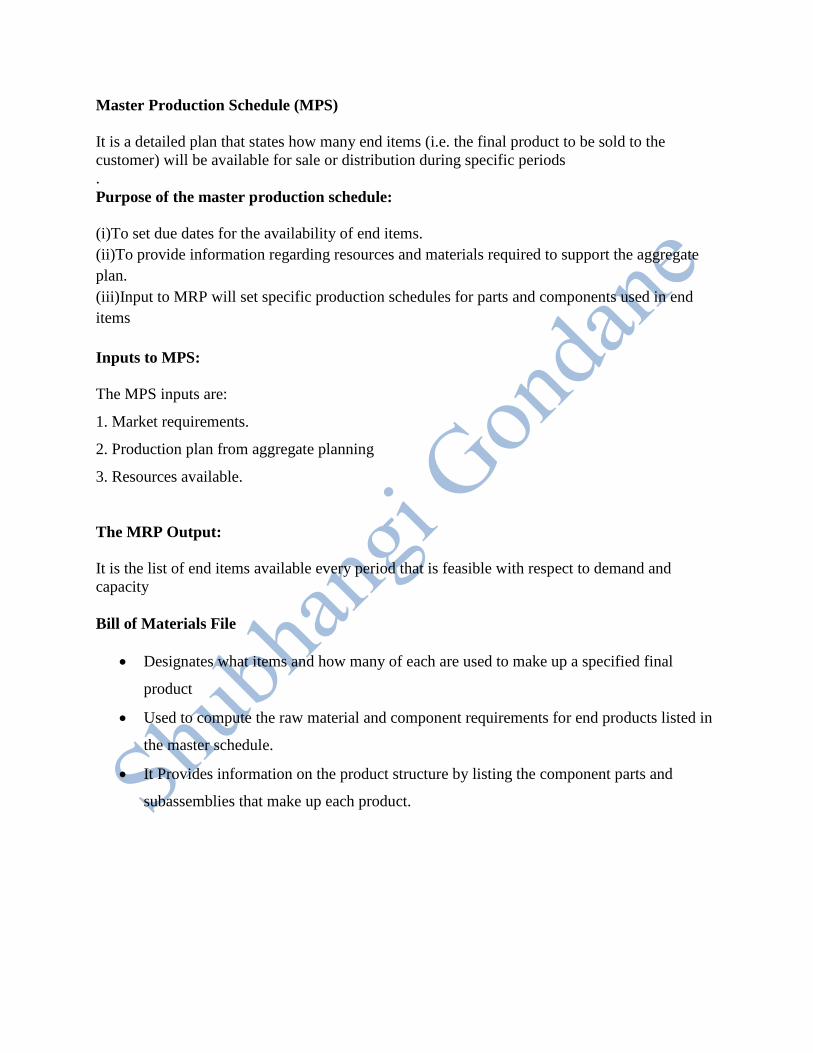
Master Production Schedule (MPS)
It is a detailed plan that states how many end items (i.e. the final product to be sold to the
customer) will be available for sale or distribution during specific periods
.
Purpose of the master production schedule:
(i)To set due dates for the availability of end items.
(ii)To provide information regarding resources and materials required to support the aggregate
plan.
(iii)Input to MRP will set specific production schedules for parts and components used in end
items
Inputs to MPS:
The MPS inputs are:
1. Market requirements.
2. Production plan from aggregate planning
3. Resources available.
The MRP Output:
It is the list of end items available every period that is feasible with respect to demand and
capacity
Bill of Materials File
Designates what items and how many of each are used to make up a specified final
product
Used to compute the raw material and component requirements for end products listed in
the master schedule.
It Provides information on the product structure by listing the component parts and
subassemblies that make up each product.

Product structure
Structure of an assembled product, in the form of a pyramid, can be depicted as shown in
Fig. It can be seen from Figure. that the product P1 is the parent of sub assemblies SA1,
SA2, and
SA3. similarly SA1 is the parent of components C1, C2 and C3, and so on
Inventory Record File
All the data related to the inventory are recorded in the inventory record file.
The inventory record file contains the following three segment
(i)Item Master Data Segment
(ii)Inventory Status Segment
(iii)Subsidiary Data Segment
Working of MRP
MPS provides a period-by-period list of final products required.
BOM defines what materials and components are needed for each product.
Inventory record file contains information on the current and future inventory status of
each component. using these three inputs, the MRP processor computes the number of
each component and raw material required for the given final product
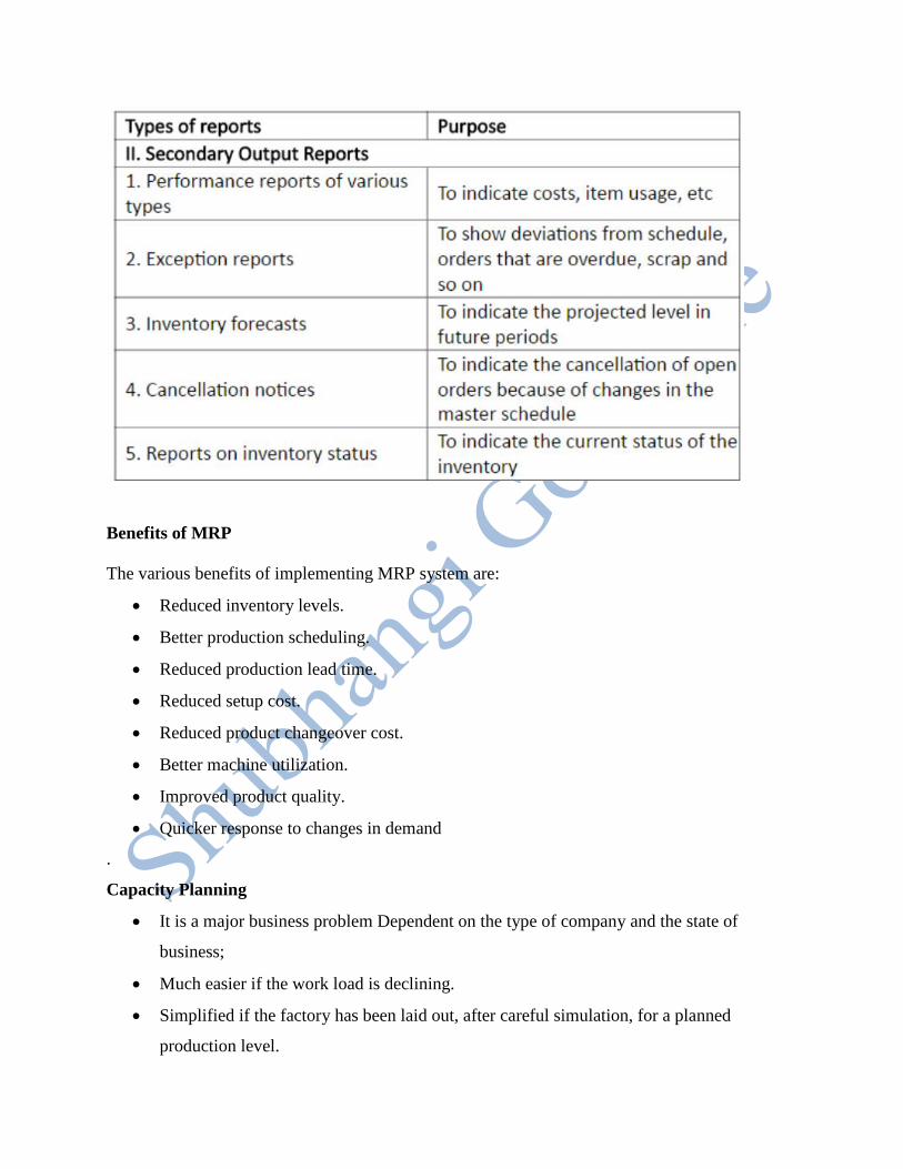
Benefits of MRP
The various benefits of implementing MRP system are:
Reduced inventory levels.
Better production scheduling.
Reduced production lead time.
Reduced setup cost.
Reduced product changeover cost.
Better machine utilization.
Improved product quality.
Quicker response to changes in demand
.
Capacity Planning
It is a major business problem Dependent on the type of company and the state of
business;
Much easier if the work load is declining.
Simplified if the factory has been laid out, after careful simulation, for a planned
production level.

It takes place in three phases, which need to be reviewed within CIM systems.
Finite capacity calculations are often optimistic, because they do not show the effect of
future work, i.e. work not yet released to the factory.
Logic Required In Capacity Planning Under CIM
The logic for detailed finite capacity planning (i.e. calculations based on actual capacity) must
include the ability to summarize the various priority factors such as lateness on due date,
important customer, accumulated cost, into a single numeric value so that queues can
be sequenced.
In addition, a number of other process routines that are as follows:
Reduction of standard inter-operation (or move) time for urgent jobs.
Overlapping of jobs across different work centers, e.g. the first items in a batch being
heat treated while the last items are still being machined.
Splitting of batches across identical machines,
Use of alternative routing data, i.e. there may be different ways of making a product that
could be chosen, depending on the load at the time on different work centers
Shop Floor Control
This control manages the detailed flow of materials inside the production facility.
It Encompasses the principles, approaches and techniques needed to schedule, control,
measure and evaluate the effectiveness of production operations.
Is an activity of production control one of the activity of process planning and control
(PPC).
To understand the significance of the shop floor control, it is essential to have the
basic knowledge of various activities of PPC and their relations to shop floor control.
It is defined as a system for utilizing data from the shop floor as well as data processing
files to maintain and communicate status information on shop orders and work centre.

Shopfloor control (SFC) is concerned with:
(i) The release of production orders to the factory.
(ii) Monitoring and controlling the progress of the orders through the various work centres.
(iii) Acquiring information on the status of the orders.
(iv)Shop floor control deals with managing the work-in-process.
Functions of Shop Floor Control
The major functions of shop floor control are:
1. Assigning priority of each shop order (Scheduling).
2. Maintaining work-in-process quantity information (Dispatching).
3. Conveying shop-order status information to the office (Follow up).
4. Providing actual output data for capacity control purposes.
5.Providing quantity by location by shop order for work-in-process inventory
and accounting purposes.
6.Providing measurement of efficiency, utilisation and productivity of manpower and machines.
The

functions of SFC are:
1. Scheduling
2. Dispatching and
3.Follow-up or Expediting.
Phases of SFC
The three important phases of SFC are:
1. Order release
2. Order scheduling and
3. Order progress.
It depicts the three phases and their relationship to other functions in the Production
management system.
In a computer integrated manufacturing system these phases are managed by computer
software.
In a typical factory which works on manual processing of data, the above documents
move with the production order and are used to track the progress through the shop.
In a CIM factory, more automated methods are used to track the progress of the
production orders

i) The first input is the authorization to produce (that derives from master schedule). This
authorisation proceeds through MRP which generates work orders with scheduling information.
(ii) The second input is the engineering and manufacturing database.
This database contains engineering data (such as the product design, component material
specifications, bills of materials, process plans, etc.) required to make the components and
assemble the products.
Database input provides the product structure and process planning information needed to
Prepare the various documents that accompany the order through the shop.
2) Order Scheduling
The two inputs required to the order scheduling are:
(i) The order release and
(ii) The priority control information
It Priority control is used in production planning and control to denote the function that
maintains the appropriate levels for the various production orders in the shop.
The order scheduling module is used to solve the following two problems in production controls:
Machine loading: Allocating orders to work centres is known as machine loading.
The term shop loading is used when loading of all machines in the plant are done.
Job sequencing: Determining the priority in which the jobs should be processed is termed
as job sequencing.
Each work centre will have a queue of orders waiting to be processed. Queue problem
can be solved by job sequencing.
Priority sequencing rules, also known as dispatching rules, have been developed to
establish priorities for production orders in the plant.

Some of the commonly used priority sequencing rules are presented below.
SOT (shortest operating time): Run the job with the shortest completion time first, next
shortest second and so on.
Earliest due date: Run the job with the earliest due date first.
STR (slack time remaining): This is calculated as the difference between the time
remaining before the due date minus the processing time remaining. Orders with the STR
are run first.
STR/OP (slack time per operation) Orders with shortest STR/OP are run first.
STR/OP is calculated as follows:
CR (critical ratio): This is calculated as the difference between the due date and the current date
divided by the number of work days remaining. Orders with the smallest CR are run first
QR (queue ratio): This is calculated as the slack time remaining in the schedule divided by the
planned remaining queue time. Orders with the smallest QR are run first
FCFS (first-come, first-served): Orders are run in the order they arrive in the department
LCFS (last-come, first-served): As orders arrive, they are placed on the top of the stock and are
run first.
3) Order Progress
The third and final phase of SFC is order progress phase.
The order progress phase monitors the status of the various orders in the plant, work-in-
progress (WIP)
Order progress collects data from shop floor and generates reports to assist production
management.
Function of order progress module is to provide information that is useful in managing
the factory based on data collected from the factory.

Inventory Control
Inventory Management:
It is defined as the scientific method of determining what to order, when to order and how
much to order and how much to stock so that costs associated with buying and storing are
optimal without interrupting production and sales.
Objective of Inventory Control
The main objectives of inventory control are:
(i) To ensure continuous supply of materials so that production should not suffer at any time.
(ii ) To maintain the overall investment in inventory at the lowest level, consistent with operating
requirements.
(iii) To minimize holding, replacement and shortage cost of inventories and maximize the
efficiency in production and distribution.
(iv) To keep inactive, waste, surplus, scrap and obsolete items at the minimum level.
(v) To supply the product, raw material, WIP, etc., to its users as per their requirements at right
time and at right price.
(vi) To ensure timely action for replenishment.
(vii) To maintain timely record of inventories of all the items and to maintain the stock within
the desired limits.
(viii) To avoid both over-stocking and under-stocking of inventory costs Associated with
Inventory (What are Inventory Costs?)
The major costs associated with procuring and holding inventories are:
1. Ordering costs
2. Carrying (or holding) costs
3. Shortage (or stock out) costs and
4. Purchase costs
It is Refer to the managerial and clerical costs to prepare the purchase or production
order.
It is also known by the names procurement costs, replenishment costs and acquisition
costs
.

These costs include:
1. Ordering costs
(i) Costs of staff of purchase department,
(ii) Costs of stationery consumed for ordering, postage, telephone bills, etc.
(iii) Depreciation costs and expenses for maintaining equipment required for ordering, receiving
and inspecting incoming items.
(iv) Inspection costs of incoming materials.
2) Holding (or inventory carrying) costs
Inventory carrying costs are the costs associated with holding a given level of inventory
on hand.
It varies in direct proportion to the amount of holding and period of holding the stock in
stores. This cost will not occur if inventory is not carried out
.
The holding costs include:
(i) Costs for storage facilities.
(ii) Handling costs.
(iii) Depreciation, taxes and insurance.
(iv) Costs on record keeping.
(v) Losses due to pilferage, spoilage, deterioration and obsolescence.
(vi)Opportunity cost of capital
3) Shortage (or stock-out) costs
When the stock of an item is depleted and there is a demand for it, then the shortage cost will
occur.
Shortage cost is the cost associated with stock-out.
The shortage costs include:
(i) Back order costs.
(ii) Loss of future sales.
(iii) Loss of customer goodwill.
(iv) Loss of profit contribution by lost sales revenue.
(iv) Extra cost associated with urgent, small quantity ordering costs.
4) Purchase (or production) costs
These are the costs incurred to purchase/or produce the item. This Costs include the price
paid or the labour, material and overhead charges necessary to produce the item.

Manufacturing Resource Planning (MRP-I)
It Represents the natural evolution of closed-loop MRP (materials requirements
planning).
It is an integrated information system that synchronizes all aspects of the business.
It is Coordinates sales, purchasing, manufacturing, finance and engineering by adopting a
focal production plan and by using one unified database to plan and update the activities
in all the systems.
MRP II consists of virtually all the functions in the PPC system (presented in Figure) plus
additional business functions that are related to production.
Manufacturing Resource Planning (MRP-II)
Important MRP II system functions include:
1. Management planning— business strategy, aggregate production planning, master production
scheduling, rough-cut capacity planning and budget planning.
2. Customer services — sales forecasting, order entry, sales analysis and finished goods
inventory.
3. Operations planning — purchase order and work order release.
4. Operations execution — purchasing, product scheduling and control, work-in- process
inventory control, shop floor control and labour hour tracking.
5. Financial functions — cost accounting, accounts receivable, accounts payable, general ledger
and payroll.
Now-a-days many commercial software are available incorporating MRP II functions with more
features.
Some of them include:
Enterprise Resource Planning (ERP)
Customer-Oriented Manufacturing Management Systems (COMMS)
Manufacturing Execution Systems (MES)
Customer-Oriented Management Systems (COMS).
Enterprise Resource Planning (ERP)
It latest step in this evolution is Enterprise Resource Planning (ERP).
Fundamentals of ERP are the same as with MRP II.

Predicts and balances demand and supply.
It is an enterprise-wide set of forecasting, planning and scheduling
tools.
Links customers and suppliers into a complete supply chain, Employs proven processes
for decision-making and Coordinates sales, marketing, operations, logistics, purchasing, finance,
product development and human resources.
Goals include high levels of customer service, productivity, cost reduction and inventory
turnover and it provides the foundation for effective supply chain management and e-commerce.

Enterprise Resource Planning is a direct outgrowth and extension of Manufacturing Resource
Planning and as such includes all of MRP II’s capabilities.
a) Applies a single set of resource planning tools across the entire enterprise
b) Provides real-time integration of sales, operating and financial data and
c) Connects resource planning approaches to the extended supply chain of customers and
suppliers.
Primary purpose of implementing Enterprise Resource Planning is to run the business, in a
rapidly changing and highly competitive environment, far better than before.
The Applicability of ERP
ERP and its predecessor, MRP II, have been successfully implemented in companies with the
following characteristics:
• Make-to-stock
• Make-to-order
• Design-to-order
• Complex
• Simple product
• Multiple plants
• Single plant
• Contract manufacturers
• Manufacturers with distribution networks
• Sell direct to end users
ERP problems fall into these four types:
The system itself is bad.
The system is good, but it's set up incorrectly.
The system is good, but it's not being used.
The system is good, but it's being used ineffectively.


![ETSI ISG CIM · [JSON-LD] 20170608 Introduction to ISG CIM CIM-002-UC CIM -003 GAP CIM-004-APIprelim CIM-005-DPP CIM-001-AB ) CIM-006-MOD0. Timeline in ToR 02/2017 First General Meeting](https://img.dokumen.tips/doc/110x75/6002860fd1e0f63f360db5f2/etsi-isg-cim-json-ld-20170608-introduction-to-isg-cim-cim-002-uc-cim-003-gap.jpg)