Embed Size (px)
Citation preview
SME 1102 - Fundamentals of Mechanical Engieering
UNIT 4 - I C ENGINES
4. HEAT ENGINES
A heat engine is a machine, which converts heat energy into mechanical energy. The
combustion of fuel such as coal, petrol, diesel generates heat. This heat is supplied to a working
substance at high temperature. By the expansion of this substance in suitable machines, heat
energy is converted into useful work. Heat engines can be further divided into two types:
(i) External combustion and
(ii) Internal combustion.
4.1 Classification of Heat Engines
4.2 External combustion engine
Here, the working medium, the steam, is generated in a boiler, located outside the engine
and allowed in to the cylinder to operate the piston to do mechanical work.
4.3 Internal combustion engine
In internal combustion engine, the combustion of fuel takes place inside the engine cylinder
and heat is generated within the cylinder. This heat is added to the air inside the cylinder and thus
the pressure of the air is increased tremendously. This high pressure air moves the piston which
rotates the crank shaft and thus mechanical work is done. Most of the internal combustion
engines are reciprocating engines with a piston that reciprocate back and forth in the cylinder.
4.4 Classification of Internal Combustion Engines
4.4.1 Based on fuel used
1. Diesel engine 2. Petrol engine 3. Gas engine
Diesel engine – Diesel is used as fuel
Petrol engine – Petrol is used as fuel
Gas engines – propane, butane or methane gases are used
4.4.2 Based ignition of fuel
1. Spark ignition engine (Carburetor type engines)
2. Compression ignition engine ( injector type engines)
Spark ignition engine – A mixture of air and fuel is drawn in to the engine cylinder. Ignition of fuel
is done by using a spark plug. The spark plug produces a spark and ignites the air- fuel mixture.
Such combustion is called constant volume combustion (C.V.C.).
Compression ignition engine – In compression ignition engines air is compressed in to the
engine cylinder,. Due to this the temperature of the compressed air rises to 700-900C. At this
stage diesel is sprayed in to the cylinder in fine particles. Due to a very high temperature, the fuel
gets ignited. This type of combustion is called constant pressure combustion (CP.C.) because the
pressure inside the cylinder is almost constant when combustion is taking place.
4.4.3 Based on working cycle
1. Four stroke cycle engine - When the cycle is completed in two revolutions of the
crankshaft, it is called four stroke cycle engine.
2. Two stroke cycle engine. - When the cycle is completed in one revolution of the
crankshaft, it is called two stroke cycle engine
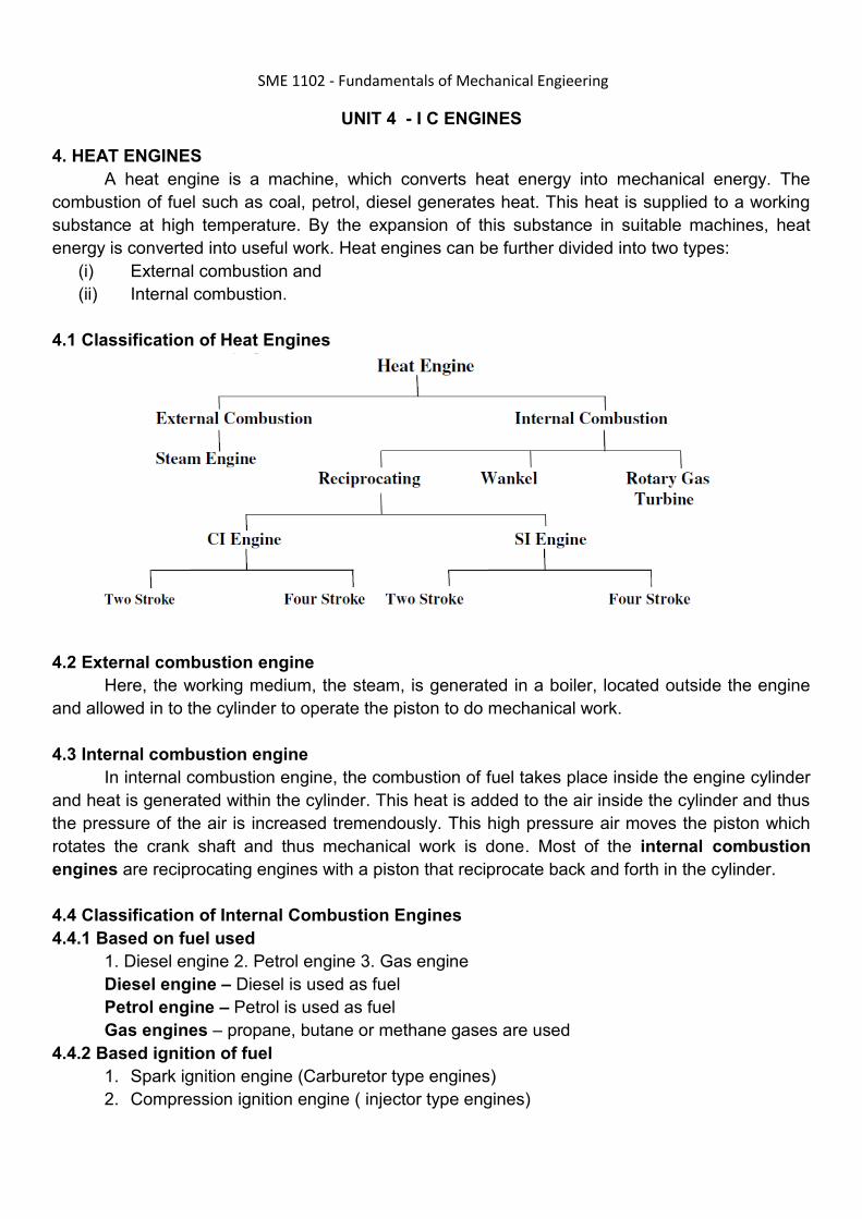
4.5 IC ENGINE COMPONENTS
Internal combustion engine consists of a number of parts which are given below :
Cylinder: It is a part of the engine which confines the expanding gases and forms the combustion
space. It is the basic part of the engine. It provides space in which piston operates to suck the air
or air-fuel mixture. The piston compresses the charge and the gas is allowed to expand in the
cylinder, transmitting power for useful work. Cylinders are usually made of high grade cast iron.
Cylinder block: It is the solid casting body which includes the cylinder and water jackets (cooling
fins in the air cooled engines).
Cylinder head: It is a detachable portion of an engine which covers the cylinder and includes the
combustion chamber, spark plugs or injector and valves.
Cylinder liner or sleeve: It is a cylindrical lining either wet or dry type which is inserted in the
cylinder block in which the piston slides. Liners are classified as: (1) Dry liner and (2) Wet liner.
Dry liner makes metal to metal contact with the cylinder block casing. wet liners come in contact
with the cooling water, whereas dry liners do not come in contact with the cooling water.
Piston: It is a cylindrical part closed at one end which maintains a close sliding fit in the engine
cylinder. It is connected to the connecting rod by a piston pin. The force of the expanding gases
against the closed end of the piston, forces the piston down in the cylinder. This causes the
connecting rod to rotate the crankshaft. Cast iron is chosen due to its high compressive strength.
Aluminum and its alloys preferred mainly due to it lightness.
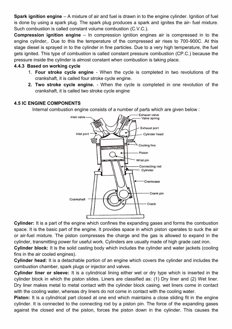
Head (Crown) of piston: It is the top of the piston.
Skirt: It is that portion of the piston below the piston pin which is designed to adsorb the side
movements of the piston.
Piston ring: It is a split expansion ring, placed in the groove of the piston. They are usually made
of cast iron or pressed steel alloy. The function of the ring are as follows :
a) It forms a gas tight combustion chamber for all positions of piston.
b) It reduces contact area between cylinder wall and piston wall preventing friction losses and
excessive wear.
c) It controls the cylinder lubrication.
d) It transmits the heat away from the piston to the cylinder walls. Piston rings are of two
types: (1) Compression ring and (2) Oil ring
Compression ring: Compression rings are usually plain, single piece and are always placed in
the grooves of the piston nearest to the piston head. They prevent leakage of gases from the
cylinder and helps increasing compression pressure inside the cylinder.
Oil ring: Oil rings are grooved or slotted and are located either in lowest groove above the piston
pin or in a groove above the piston skirt. They control the distribution of lubrication oil in the
cylinder and the piston.
Piston Pin: It is also called wrist pin or gudgeon pin. Piston pin is used to join the connecting rod
to the piston.
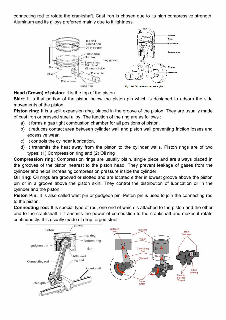
Connecting rod: It is special type of rod, one end of which is attached to the piston and the other
end to the crankshaft. It transmits the power of combustion to the crankshaft and makes it rotate
continuously. It is usually made of drop forged steel.

Crankshaft: It is the main shaft of an engine which converts the reciprocating motion of the piston
into rotary motion of the flywheel. Usually the crankshaft is made of drop forged steel or cast steel.
The space that supports the crankshaft in the cylinder block is called main journal, whereas the
part to which connecting rod is attached is known as crank journal. Crankshaft is provided with
counter weights throughout its length to have counter balance of the unit.
Flywheel: Flywheel is made of cast iron. Its main functions are as follows :
a) It stores energy during power stroke and returns back the energy during the idle strokes,
providing a uniform rotary motion of flywheel.
b) The rear surface of the flywheel serves as one of the pressure surfaces for the clutch plate.
c) Engine timing marks are usually stamped on the flywheel, which helps in adjusting the
timing of the engine.
d) Sometime the flywheel serves the purpose of a pulley for transmitting power.
Crankcase: The crankcase is that part of the engine which supports and encloses
the crankshaft and camshaft. It provides a reservoir for the lubricating oil. It also serves as a
mounting unit for such accessories as the oil pump, oil filter, starting motor and ignition
components. The upper portion of the crankcase is usually integral with cylinder block. The lower
part of the crankcase is commonly called oil pan and is usually made of cast iron or cast
aluminum.
Camshaft: It is a shaft which raises and lowers the inlet and exhaust valves at proper times.
Camshaft is driven by crankshaft by means of gears, chains or sprockets. The speed of the
camshaft is exactly half the speed of the crankshaft in four stroke engine. Camshaft operates the
ignition timing mechanism, lubricating oil pump and fuel pump. It is mounted in the crankcase,
parallel to the crankshaft.
Timing gear: Timing gear is a combination of gears, one gear of which is mounted at one end of
the camshaft and the other gear at the crankshaft. Camshaft gear is bigger in size than that of the
crankshaft gear and it has twice as many teeth as that of the crankshaft gear. For this reason, this
gear is commonly called half time gear. Timing gear controls the timing of ignition, timing of
opening and closing of valve as well as fuel injection timing.
Inlet manifold: It is that part of the engine through which air or air-fuel mixture enters into the
engine cylinder. It is fitted by the side of the cylinder head.
Exhaust manifold: It is that part of the engine through which exhaust gases go out of the engine
cylinder. It is capable of withstanding high temperature of burnt gases. It is fitted by the side of the
cylinder head.
4.6 IC ENGINE TERMINOLOGIES
Bore- Bore is the diameter of the engine cylinder.
Stroke - It is the linear distance traveled by the piston from Top dead centre (TDC) to Bottom
dead centre (BDC).
Stroke-bore ratio -The ratio of length of stroke (L) and diameter of bore (D) of the cylinder is
called stroke-bore ratio (L/D). In general, this ratio varies between 1 to 1.45 and for tractor
engines, this ratio is about 1.25.
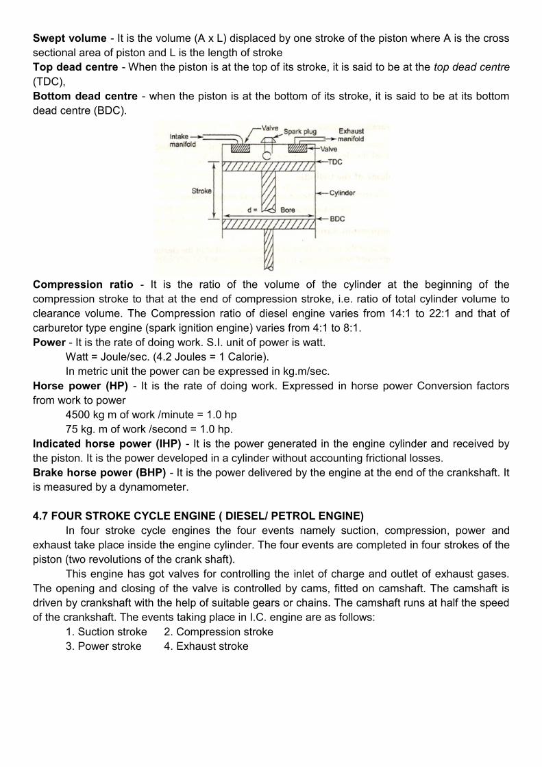
Swept volume - It is the volume (A x L) displaced by one stroke of the piston where A is the cross
sectional area of piston and L is the length of stroke
Top dead centre - When the piston is at the top of its stroke, it is said to be at the top dead centre
(TDC),
Bottom dead centre - when the piston is at the bottom of its stroke, it is said to be at its bottom
dead centre (BDC).
Compression ratio - It is the ratio of the volume of the cylinder at the beginning of the
compression stroke to that at the end of compression stroke, i.e. ratio of total cylinder volume to
clearance volume. The Compression ratio of diesel engine varies from 14:1 to 22:1 and that of
carburetor type engine (spark ignition engine) varies from 4:1 to 8:1.
Power - It is the rate of doing work. S.I. unit of power is watt.
Watt = Joule/sec. (4.2 Joules = 1 Calorie).
In metric unit the power can be expressed in kg.m/sec.
Horse power (HP) - It is the rate of doing work. Expressed in horse power Conversion factors
from work to power
4500 kg m of work /minute = 1.0 hp
75 kg. m of work /second = 1.0 hp.
Indicated horse power (IHP) - It is the power generated in the engine cylinder and received by
the piston. It is the power developed in a cylinder without accounting frictional losses.
Brake horse power (BHP) - It is the power delivered by the engine at the end of the crankshaft. It
is measured by a dynamometer.
4.7 FOUR STROKE CYCLE ENGINE ( DIESEL/ PETROL ENGINE)
In four stroke cycle engines the four events namely suction, compression, power and
exhaust take place inside the engine cylinder. The four events are completed in four strokes of the
piston (two revolutions of the crank shaft).
This engine has got valves for controlling the inlet of charge and outlet of exhaust gases.
The opening and closing of the valve is controlled by cams, fitted on camshaft. The camshaft is
driven by crankshaft with the help of suitable gears or chains. The camshaft runs at half the speed
of the crankshaft. The events taking place in I.C. engine are as follows:
1. Suction stroke 2. Compression stroke
3. Power stroke 4. Exhaust stroke

Suction stroke
During suction stroke inlet valve opens and the piston moves downward. Only air or a
mixture of air and fuel are drawn inside the cylinder. The exhaust valve remains in closed position
during this stroke. The pressure in the engine cylinder is less than atmospheric pressure during
this stroke.
Compression stroke
During this stroke the piston moves upward. Both valves are in closed position. The charge
taken in the cylinder is compressed by the upward movement of piston. If only air is compressed,
as in case of diesel engine, diesel is injected at the end of the compression stroke and ignition of
fuel takes place due to high pressure and temperature of the compressed air. If a mixture of air
and fuel is compressed in the cylinder, as in case of petrol engine, the mixture is ignited by a spark
plug.
Power stroke
After ignition of fuel, tremendous amount of heat is generated, causing very high pressure
in the cylinder which pushes the piston downward. The downward movement of the piston at this
instant is called power stroke. The connecting rod transmits the power from piston to the crank
shaft and crank shaft rotates. Mechanical work can be taped at the rotating crank shaft. Both
valves remain closed during power stroke.
Exhaust stroke
During this stroke piston moves upward. Exhaust valve opens and exhaust gases go out
through exhaust valves opening. All the burnt gases go out of the engine and the cylinder

becomes ready to receive the fresh charge. During this stroke inlet valve remains closed. Thus it is
found that out of four strokes, there is only one power stroke and three idle strokes in four stroke
cycle engine. The power stroke supplies necessary momentum for useful work.
4.8 TWO STROKE CYCLE ENGINE (PETROL ENGINE)
In two stroke cycle engines, the whole sequence of events i.e., suction, compression,
power and exhaust are completed in two strokes of the piston i.e. one revolution of the crankshaft.
There is no valve in this type of engine. Gas movement takes place through holes called ports in
the cylinder. The crankcase of the engine is air tight in which the crankshaft rotates.
Upward stroke of the piston (Suction + Compression)
When the piston moves upward it covers two of the ports, the exhaust port and transfer
port, which are normally almost opposite to each other. This traps the charge of air- fuel mixture
drawn already in to the cylinder. Further upward movement of the piston compresses the charge
and also uncovers the suction port. Now fresh mixture is drawn through this port into the
crankcase. Just before the end of this stroke, the mixture in the cylinder is ignited by a spark plug
Thus, during this stroke both suction and compression events are completed.
Downward stroke (Power + Exhaust)
Burning of the fuel rises the temperature and pressure of the gases which forces the piston
to move down the cylinder. When the piston moves down, it closes the suction port, trapping the
fresh charge drawn into the crankcase during the previous upward stroke. Further downward
movement of the piston uncovers first the exhaust port and then the transfer port. Now fresh
charge in the crankcase moves in to the cylinder through the transfer port driving out the burnt
gases through the exhaust port. Special shaped piston crown deflect the incoming mixture up
around the cylinder so that it can help in driving out the exhaust gases . During the downward
stroke of the piston power and exhaust events are completed.
4.9 COMPARISON OF CI AND SI ENGINES
The CI engine has the following advantages over the SI engine.
1. Reliability of the CI engine is much higher than that of the SI engine. This is because in
case of the failure of the battery, ignition or carburetor system, the SI engine cannot
operate, whereas the CI engine, with a separate fuel injector for each cylinder, has less risk
of failure.
2. The distribution of fuel to each cylinder is uniform as each of them has a separate injector,
whereas in the SI engine the distribution of fuel mixture is not uniform, owing to the design
of the single carburetor and the intake manifold.
3. Since the servicing period of the fuel injection system of CI engine is longer, its
maintenance cost is less than that of the SI engine.
4. The expansion ratio of the CI engine is higher than that of the SI engine; therefore, the heat
loss to the cylinder walls is less in the CI engine than that of the SI engine. Consequently,
the cooling system of the CI engine can be of smaller dimensions.
5. The torque characteristics of the CI engine are more uniform which results in better top
gear performance.
6. The CI engine can be switched over from part load to full load soon after starting from cold,
whereas the SI engine requires warming up.
7. The fuel (diesel) for the CI engine is cheaper than the fuel (petrol) for SI engine.
8. The fire risk in the CI engine is minimized due to the absence of the ignition system.

9. On part load, the specific fuel consumption of the CI engine is low.
4.10 ADVANTAGES AND DISADVANTAGES OF TWO-STROKE CYCLE OVER FOUR-
STROKE CYCLE ENGINES
Advantages:
1) The two-stroke cycle engine gives one working stroke for each revolution of the crankshaft.
Hence theoretically the power developed for the same engine speed and cylinder volume is
twice that of the four-stroke cycle engine, which gives only one working stroke for every two
revolutions of the crankshaft. However, in practice, because of poor scavenging, only 50-
60% extra power is developed.
2) Due to one working stroke for each revolution of the crankshaft, the turning moment on the
crankshaft is more uniform. Therefore, a two-stroke engine requires a lighter flywheel.
3) The two-stroke engine is simpler in construction. The design of its ports is much simpler
and their maintenance easier than that of the valve mechanism.
4) The power required to overcome frictional resistance of the suction and exhaust strokes is
saved, resulting in some economy of fuel.
5) Owing to the absence of the cam, camshaft, rockers, etc. of the valve mechanism, the
mechanical efficiency is higher.
6) The two-stroke engine gives fewer oscillations.
7) For the same power, a two-stroke engine is more compact and requires less space than a
four-stroke cycle engine. This makes it more suitable for use in small machines and
motorcycles.
8) A two-stroke engine is lighter in weight for the same power and speed especially when the
crankcase compression is used.
9) Due to its simpler design, it requires fewer spare parts.
10) A two-stroke cycle engine can be easily reversed if it is of the valve less type.
Disadvantages:
1. The scavenging being not very efficient in a two-stroke engine, the dilution of the charges
takes place which results in poor thermal efficiency.
2. The two-stroke spark ignition engines do not have a separate lubrication system and
normally, lubricating oil is mixed with the fuel. This is not as effective as the lubrication of a
four-stroke engine. Therefore, the parts of the two-stroke engine are subjected to greater
wear and tear.
3. In a spark ignition two-stroke engine, some of the fuel passes directly to the exhaust.
Hence, the fuel consumption per horsepower is comparatively higher.
4. With heavy loads a two-stroke engine gets heated up due to the excessive heat produced.
At the same time the running of the engine is riot very smooth at light loads.
5. It consumes more lubricating oil because of the greater amount of heat generated.
6. Since the ports remain open during the upward stroke, the actual compression starts only
after both the inlet and exhaust ports have been closed. Hence, the compression ratio of
this engine is lower than that of a four-stroke engine of the same dimensions. As the
efficiency of an engine is directly proportional to its compression ratio, the efficiency of a
two-stroke cycle engine is lower than that of a four-stroke cycle engine of the same size.
4.11 IGNITION SYSTEM TYPES
Basically Convectional Ignition systems are of 2 types :
a) Battery or Coil Ignition System, and
b) Magneto Ignition System.

Both these conventional, ignition systems work on mutual electromagnetic induction
principle.
Battery ignition system was generally used in 4-wheelers, but now-a-days it is more
commonly used in 2-wheelers also (i.e. Button start, 2-wheelers like Pulsar, Kinetic Honda;
Honda-Activa, Scooty, Fiero, etc.). In this case 6 V or 12 V batteries will supply necessary
current in the primary winding.
Magneto ignition system is mainly used in 2-wheelers, kick start engines. (Example, Bajaj
Scooters, Boxer, Victor, Splendor, Passion, etc.).
In this case magneto will produce and supply current to the primary winding. So in magneto
ignition system magneto replaces the battery.
4.11.1 Battery or Coil Ignition System
Figure shows line diagram of battery ignition system for a 4-cylinder petrol engine. It mainly
consists of a 6 or 12 volt battery, ammeter, ignition switch, auto-transformer (step up transformer),
contact breaker, capacitor, distributor rotor, distributor contact points, spark plugs, etc. Note that
the Figure 4.1 shows the ignition system for 4-cylinder petrol engine,
here there are 4-spark plugs and contact breaker cam has 4-corners. (If it is for 6-cylinder engine it
will have 6-spark plugs and contact breaker cam will be a perfect hexagon).
The ignition system is divided into 2-circuits :
(i) Primary Circuit : It consists of 6 or 12 V battery, ammeter, ignition switch, primary
winding it has 200-300 turns of 20 SWG (Sharps Wire Gauge) gauge wire, contact
breaker, capacitor.
(ii) Secondary Circuit : It consists of secondary winding. Secondary winding consists of
about 21000 turns of 40 (S WG) gauge wire. Bottom end of which is connected to bottom
end of primary and top end of secondary winding is connected to centre of distributor
rotor. Distributor rotors rotate and make contacts with contact points and are connected to
spark plugs which are fitted in cylinder heads (engine earth).
(iii) Working : When the ignition switch is closed and engine in cranked, as soon as the
contact breaker closes, a low voltage current will flow through the primary winding. It is
also to be noted that the contact beaker cam opens and closes the circuit 4-times (for 4
cylinders) in one revolution. When the contact breaker opens the contact, the magnetic
field begins to collapse. Because of this collapsing magnetic field, current will be induced
in the secondary winding. And because of more turns (@ 21000 turns) of secondary,
voltage goes unto 28000-30000 volts.

This high voltage current is brought to centre of the distributor rotor. Distributor rotor rotates
and supplies this high voltage current to proper stark plug depending upon the engine firing order.
When the high voltage current jumps the spark plug gap, it produces the spark and the charge is
ignited-combustion starts-products of combustion expand and produce power.
4.11.2 Magneto Ignition System
In this case magneto will produce and supply the required current to the primary winding. In
this case as shown, we can have rotating magneto with fixed coil or rotating coil with fixed
magneto for producing and supplying current to primary, remaining arrangement is same as that of
a battery ignition system.
Comparison Between Battery and Magneto Ignition System
Disadvantages of Conventional Ignition Systems
Following are the drawbacks of conventional ignition systems :
(a) Because of arcing, pitting of contact breaker point and which will lead to regular
maintenance problems.
(b) Poor starting : After few thousands of kilometers of running, the timing becomes inaccurate,
which results into poor starting (Starting trouble).
(c) At very high engine speed, performance is poor because of inertia effects of the moving
parts in the system.
(d) Sometimes it is not possible to produce spark properly in fouled spark plugs.
Advantages of Electronic Ignition System
Following are the advantages of electronic ignition system :
(a) Moving parts are absent-so no maintenance.
(b) Contact breaker points are absent-so no arcing.
(c) Spark plug life increases by 50% and they can be used for about 60000 km without any
problem.
(d) Better combustion in combustion chamber, about 90-95% of air fuel mixture is burnt
compared with 70-75% with conventional ignition system.
(e) More power output.
(f) More fuel efficiency.
4.11.3 Types of Electronic Ignition System
Electronic Ignition System is as follow :
(a) Capacitance Discharge Ignition system
(b) Transistorized system
(c) Piezo-electric Ignition system
(d) The Texaco Ignition system
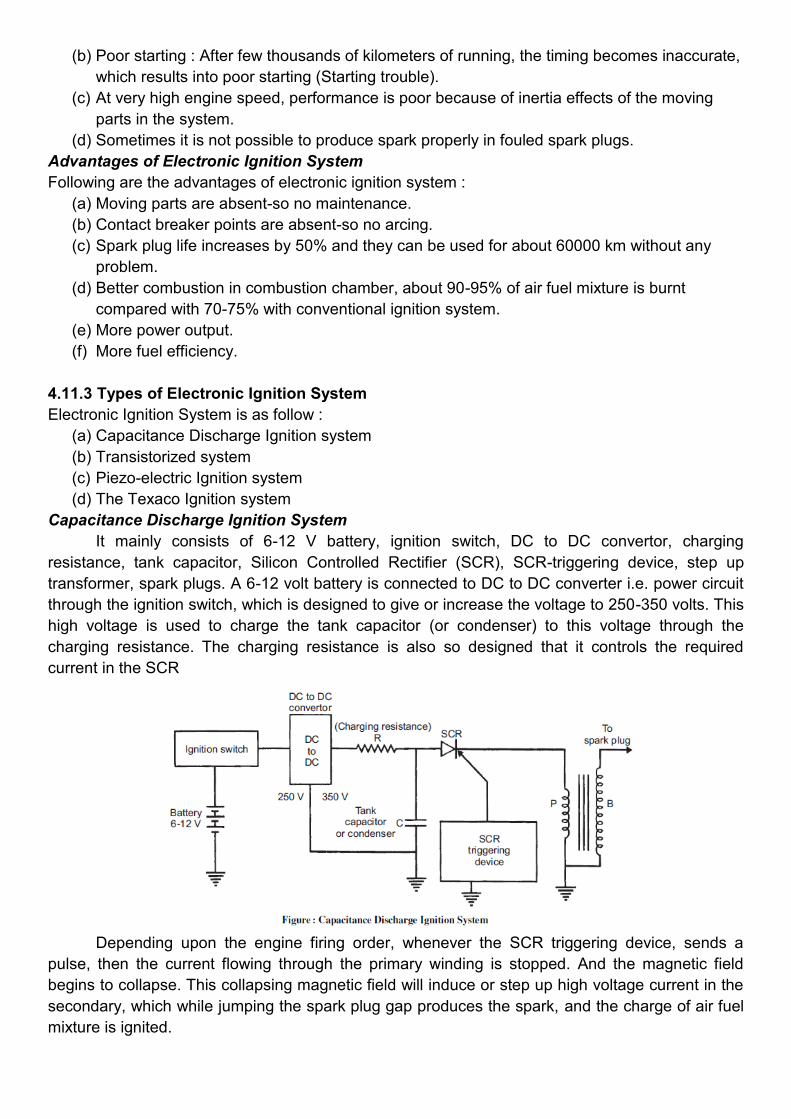
Capacitance Discharge Ignition System
It mainly consists of 6-12 V battery, ignition switch, DC to DC convertor, charging
resistance, tank capacitor, Silicon Controlled Rectifier (SCR), SCR-triggering device, step up
transformer, spark plugs. A 6-12 volt battery is connected to DC to DC converter i.e. power circuit
through the ignition switch, which is designed to give or increase the voltage to 250-350 volts. This
high voltage is used to charge the tank capacitor (or condenser) to this voltage through the
charging resistance. The charging resistance is also so designed that it controls the required
current in the SCR
Depending upon the engine firing order, whenever the SCR triggering device, sends a
pulse, then the current flowing through the primary winding is stopped. And the magnetic field
begins to collapse. This collapsing magnetic field will induce or step up high voltage current in the
secondary, which while jumping the spark plug gap produces the spark, and the charge of air fuel
mixture is ignited.

Transistorized Assisted Contact (TAC) Ignition System
Figure shows the TAC system.
Advantages
(a) The low breaker-current ensures longer life.
(b) The smaller gap and lighter point assembly increase dwell time minimize contact bouncing and
improve repeatability of secondary voltage.
(c) The low primary inductance reduces primary inductance reduces primary current drop-off at
high speeds.
Disadvantages
(a) As in the conventional system, mechanical breaker points are necessary for timing the spark.
(b) The cost of the ignition system is increased.
(c) The voltage rise-time at the spark plug is about the same as before.
Piezo-electric Ignition System
The development of synthetic piezo-electric materials producing about 22 kV by mechanical
loading of a small crystal resulted in some ignition systems for single cylinder engines. But due to
difficulties of high mechanical loading need of the order of 500 kg timely control and ability to
produce sufficient voltage, these systems have not been able to come up.
The Texaco Ignition System
Due to the increased emphasis on exhaust emission control, there has been a sudden interest in
exhaust gas recirculation systems and lean fuel-air mixtures. To avoid the problems of burning of
lean mixtures, the Texaco Ignition system has
been developed. It provides a spark of controlled duration which means that the spark duration in
crank angle degrees can be made constant at all engine speeds. It is a AC system. This system
consists of three basic units, a power unit, a control
unit and a distributor sensor. This system can give stable ignition up to A/F ratios as high as 24 : 1.
4.12 Fuel Pump
4.12.1. Mechanical type fuel transfer pump
The fuel system of a vehicle is operated by an eccentric, mounted on a camshaft of an engine.
The pump consists of a spring loaded flexible diaphragm actuated by a rocker arm. The rocker
arm is actuated by the eccentric. Spring loaded valves are there in the inlet and outlet of the pump.
These valves ensure flow of fuel in the proper direction.
As the rocker arm is moved by the eccentric, the diaphragm is pulled down against the
spring force. This movement causes a partial vacuum in the pump chamber. Now the delivery
valve remains closed and the suction valve opens. This admits fuel into the pump chamber. At the
maximum position of the eccentric, the diaphragm is flexed to the maximum extent. After this,
further rotation of the eccentric will release the rocker arm. Now the rocker arm will simply follow
the eccentric by the action of the return spring. The diaphragm spring will now push the diaphragm
upwards and force the fuel to flow out, opening the delivery valve, into the delivery tube. Now the
suction valve remains closed.
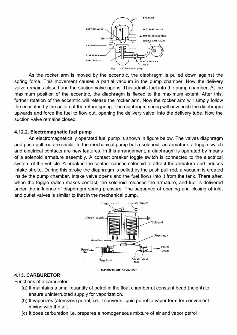
4.12.2. Electromagnetic fuel pump
An electromagnetically operated fuel pump is shown in figure below. The valves diaphragm
and push pull rod are similar to the mechanical pump but a solenoid, an armature, a toggle switch
and electrical contacts are new features. In this arrangement, a diaphragm is operated by means
of a solenoid armature assembly. A contact breaker toggle switch is connected to the electrical
system of the vehicle. A break in the contact causes solenoid to attract the armature and induces
intake stroke. During this stroke the diaphragm is pulled by the push pull rod, a vacuum is created
inside the pump chamber, intake valve opens and the fuel flows into it from the tank. There after,
when the toggle switch makes contact, the solenoid releases the armature, and fuel is delivered
under the influence of diaphragm spring pressure. The sequence of opening and closing of inlet
and outlet valves is similar to that in the mechanical pump.
4.13. CARBURETOR
Functions of a carburetor:
(a) It maintains a small quantity of petrol in the float chamber at constant head (height) to
ensure uninterrupted supply for vaporization.
(b) It vaporizes (atomizes) petrol, i.e. it converts liquid petrol to vapor form for convenient
mixing with the air.
(c) It does carburetion i.e. prepares a homogeneous mixture of air and vapor petrol
(d) It delivers correct air-fuel mixture to the engine through the manifold under varying
conditions of load and speed of the engine.
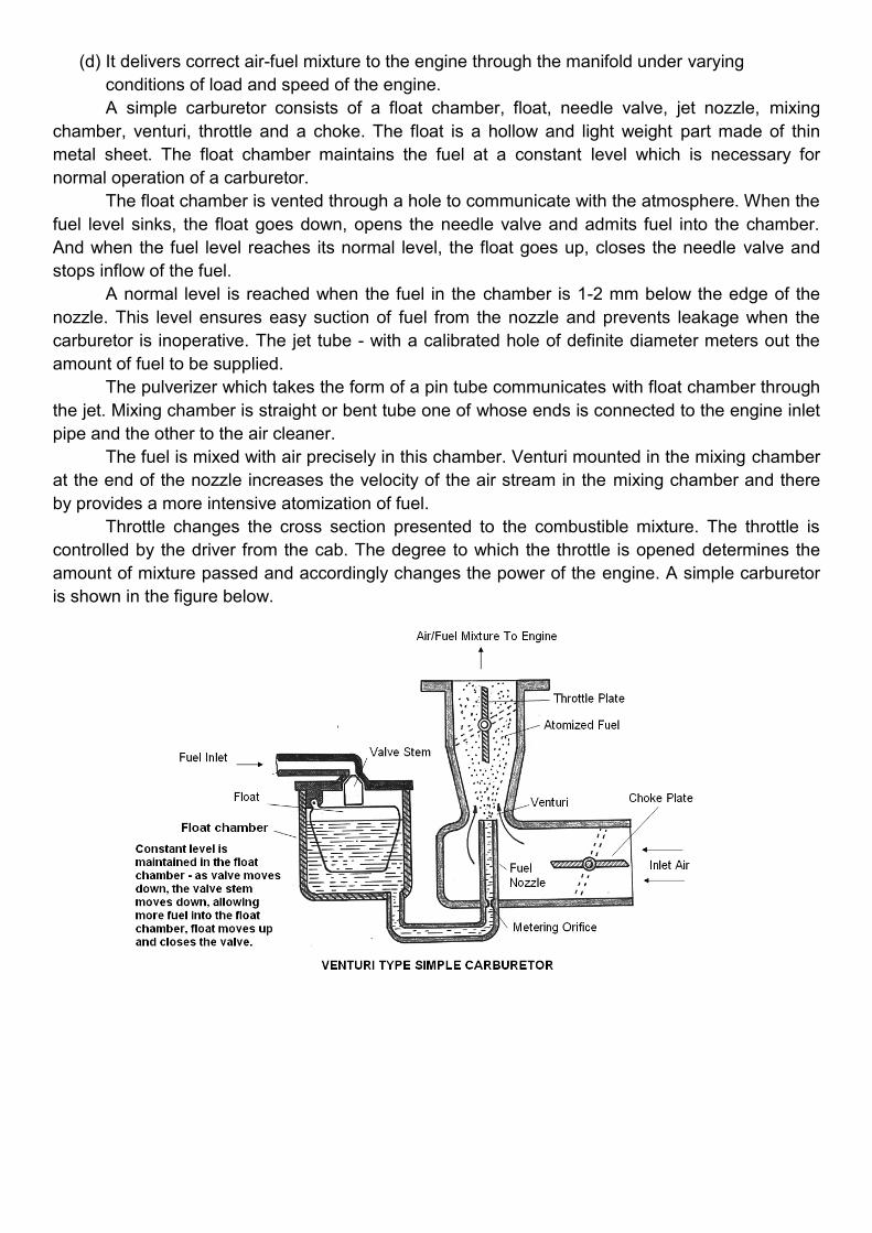
A simple carburetor consists of a float chamber, float, needle valve, jet nozzle, mixing
chamber, venturi, throttle and a choke. The float is a hollow and light weight part made of thin
metal sheet. The float chamber maintains the fuel at a constant level which is necessary for
normal operation of a carburetor.
The float chamber is vented through a hole to communicate with the atmosphere. When the
fuel level sinks, the float goes down, opens the needle valve and admits fuel into the chamber.
And when the fuel level reaches its normal level, the float goes up, closes the needle valve and
stops inflow of the fuel.
A normal level is reached when the fuel in the chamber is 1-2 mm below the edge of the
nozzle. This level ensures easy suction of fuel from the nozzle and prevents leakage when the
carburetor is inoperative. The jet tube - with a calibrated hole of definite diameter meters out the
amount of fuel to be supplied.
The pulverizer which takes the form of a pin tube communicates with float chamber through
the jet. Mixing chamber is straight or bent tube one of whose ends is connected to the engine inlet
pipe and the other to the air cleaner.
The fuel is mixed with air precisely in this chamber. Venturi mounted in the mixing chamber
at the end of the nozzle increases the velocity of the air stream in the mixing chamber and there
by provides a more intensive atomization of fuel.
Throttle changes the cross section presented to the combustible mixture. The throttle is
controlled by the driver from the cab. The degree to which the throttle is opened determines the
amount of mixture passed and accordingly changes the power of the engine. A simple carburetor
is shown in the figure below.
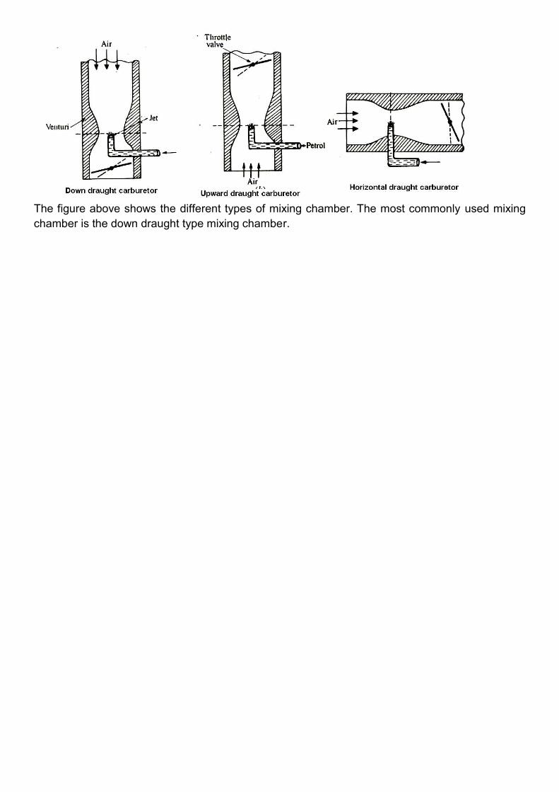
The figure above shows the different types of mixing chamber. The most commonly used mixing
chamber is the down draught type mixing chamber.