Embed Size (px)
Citation preview

Unit 4: Electricity (Part 1)
Learning Outcomes
Students should be able to:
1. Explain what is meant by current, potential
difference and resistance, stating their units
2. Draw and interpret circuit diagrams and set up
circuits containing electrical sources, switches,
lamps resistors (fixed and variable), ammeters and
voltmeters
3. Recognize that the resistance of a circuit can be
varied by arranging resistors in series or in parallel
4. Explain qualitatively the chemical, heating and
magnetic effects of an electric current and list
some of its applications.
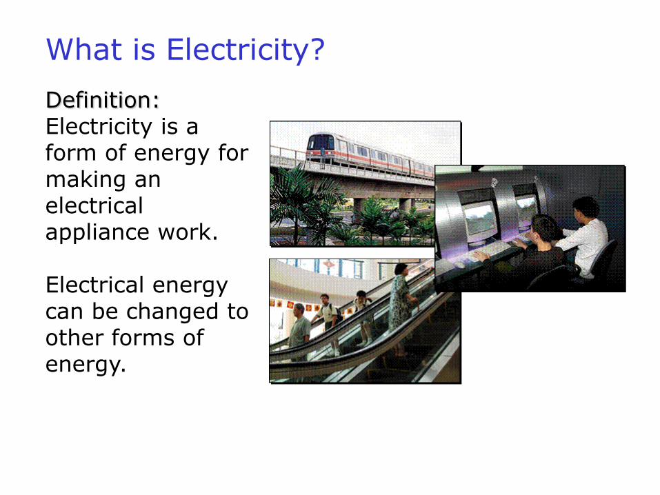
Definition:Electricity is a form of energy for making an electrical appliance work.
Electrical energy can be changed to other forms of energy.
What is Electricity?
Sources of Electricity
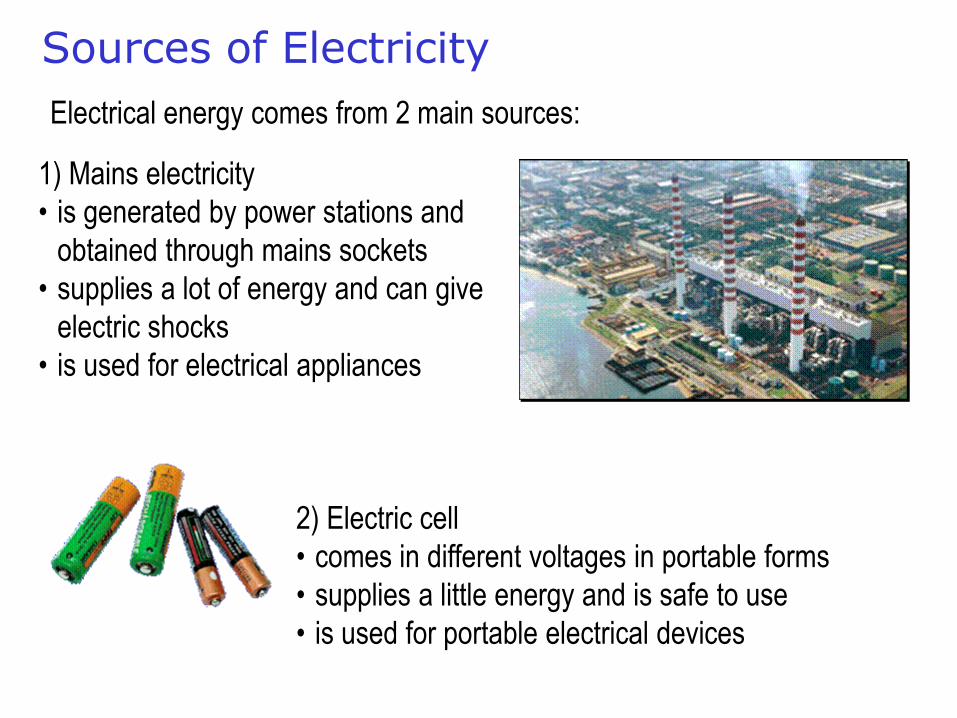
Electrical energy comes from 2 main sources:
1) Mains electricity
• is generated by power stations and
obtained through mains sockets
• supplies a lot of energy and can give
electric shocks
• is used for electrical appliances
2) Electric cell
• comes in different voltages in portable forms
• supplies a little energy and is safe to use
• is used for portable electrical devices
Electric Circuits
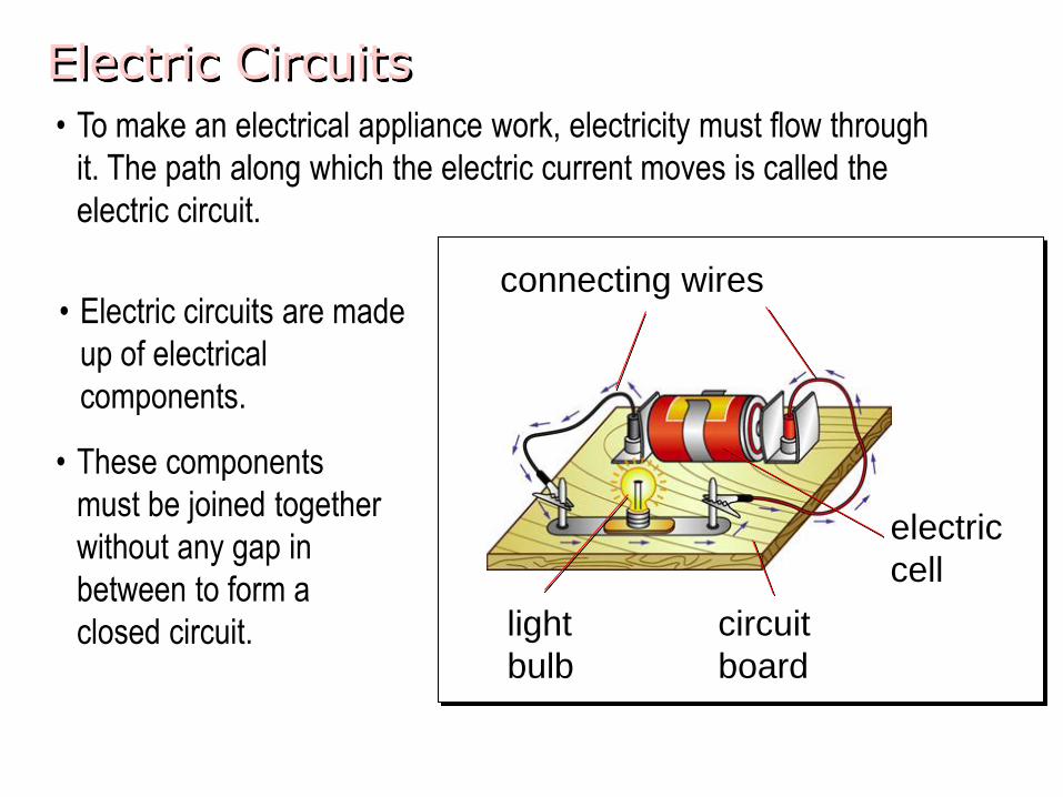
• Electric circuits are made
up of electrical
components.
• These components
must be joined together
without any gap in
between to form a
closed circuit.
connecting wires
electric
cell
circuit
board
light
bulb
• To make an electrical appliance work, electricity must flow through
it. The path along which the electric current moves is called the
electric circuit.
Electric Circuits
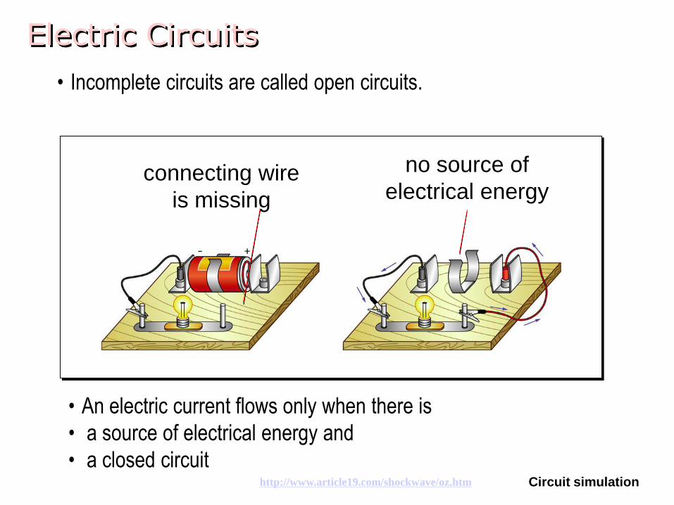
• Incomplete circuits are called open circuits.
• An electric current flows only when there is
• a source of electrical energy and
• a closed circuit
connecting wire
is missing
no source of
electrical energy
Circuit simulationhttp://www.article19.com/shockwave/oz.htm
Circuit Diagrams
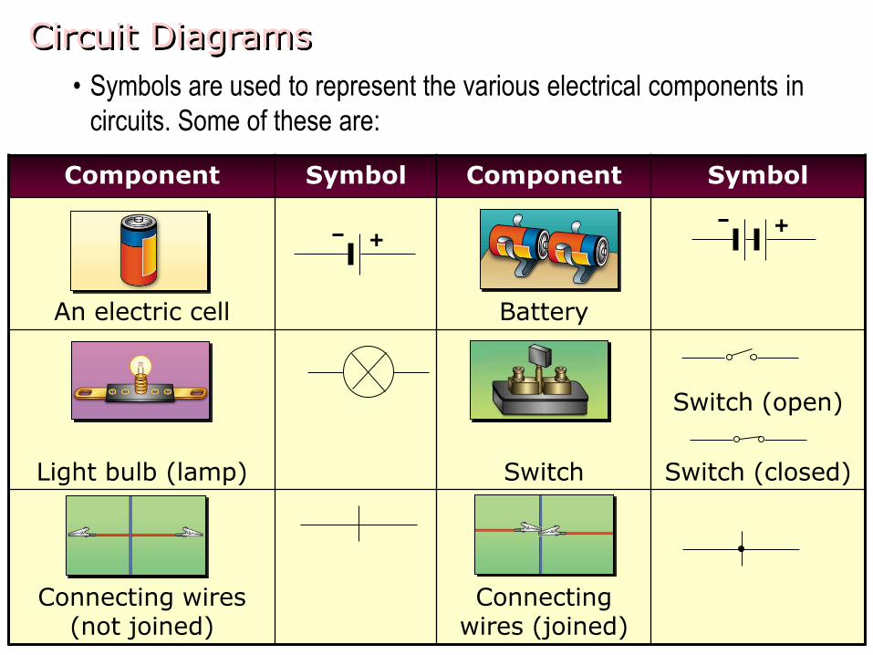
• Symbols are used to represent the various electrical components in
circuits. Some of these are:
Component Symbol Component Symbol
An electric cell Battery
Light bulb (lamp) Switch
Switch (open)
Switch (closed)
Connecting wires (not joined)
Connecting wires (joined)
++
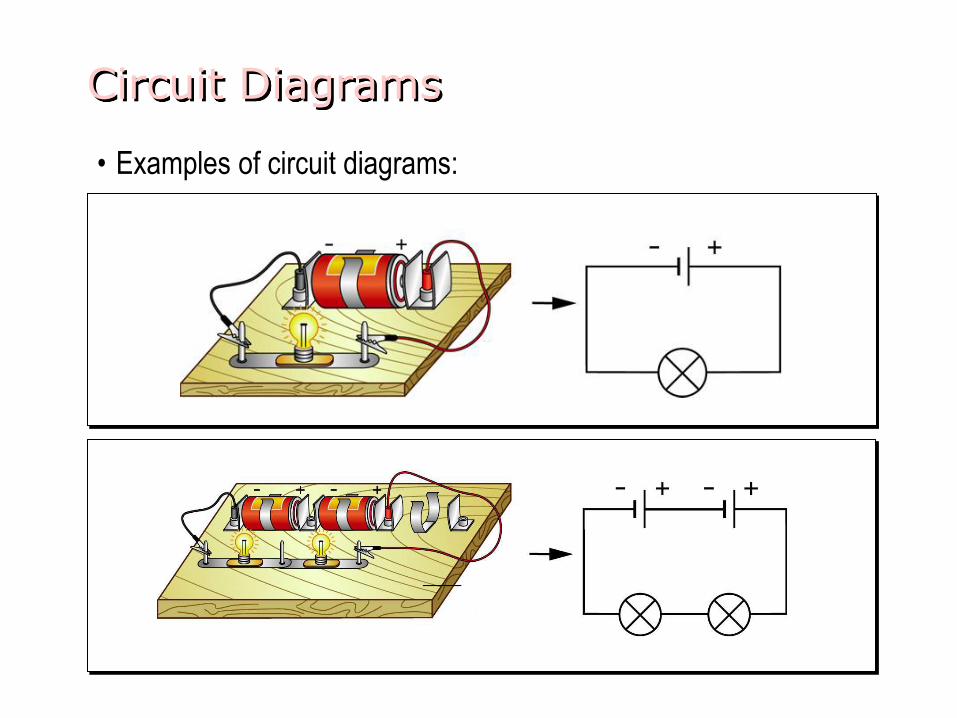
Circuit Diagrams
• Examples of circuit diagrams:
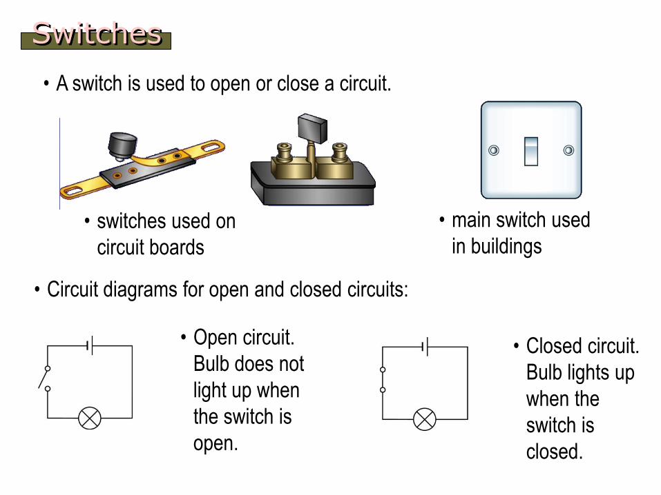
Switches
• A switch is used to open or close a circuit.
• main switch used
in buildings• switches used on
circuit boards
• Open circuit.
Bulb does not
light up when
the switch is
open.
• Closed circuit.
Bulb lights up
when the
switch is
closed.
• Circuit diagrams for open and closed circuits:
Series and Parallel Circuits
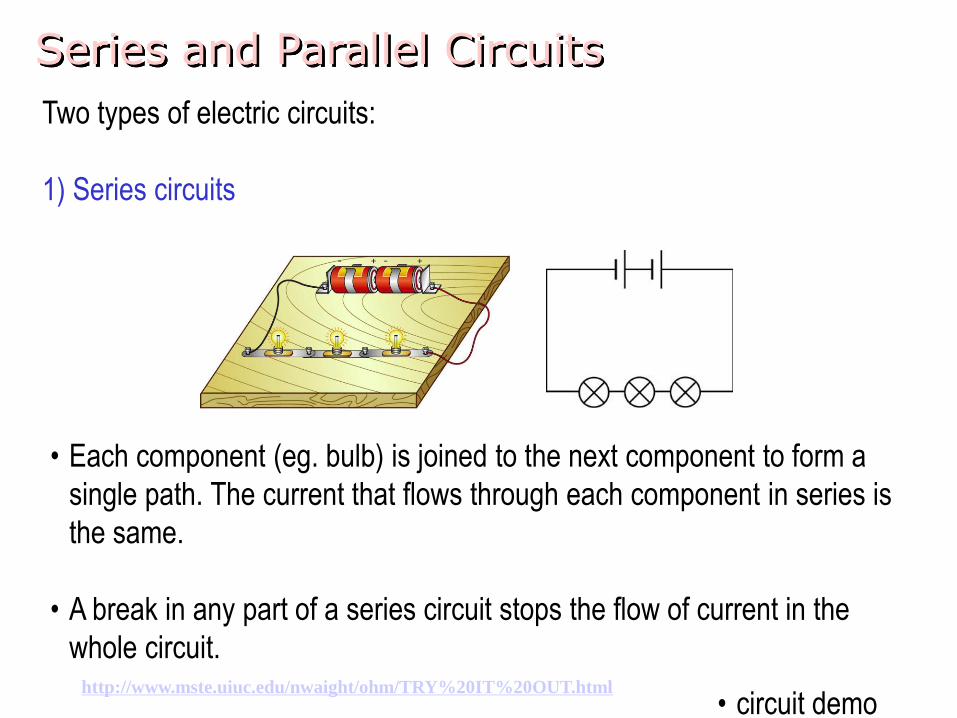
Two types of electric circuits:
1) Series circuits
• Each component (eg. bulb) is joined to the next component to form a
single path. The current that flows through each component in series is
the same.
• A break in any part of a series circuit stops the flow of current in the
whole circuit.
• circuit demohttp://www.mste.uiuc.edu/nwaight/ohm/TRY%20IT%20OUT.html
Series and Parallel Circuits
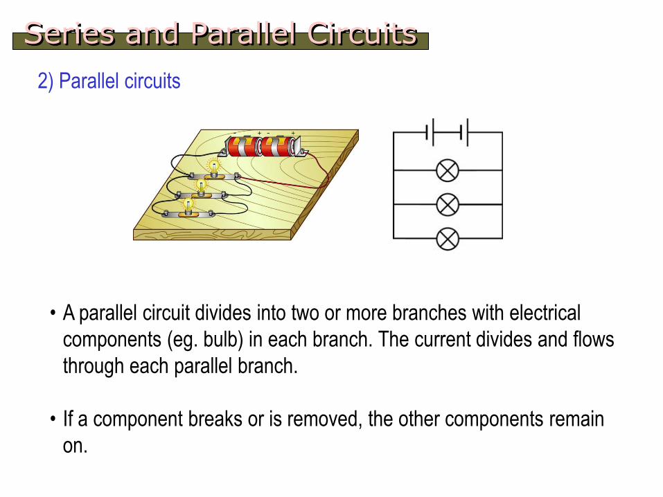
2) Parallel circuits
• A parallel circuit divides into two or more branches with electrical
components (eg. bulb) in each branch. The current divides and flows
through each parallel branch.
• If a component breaks or is removed, the other components remain
on.
- What is it?
- Can we measure it?
- How do we measure?
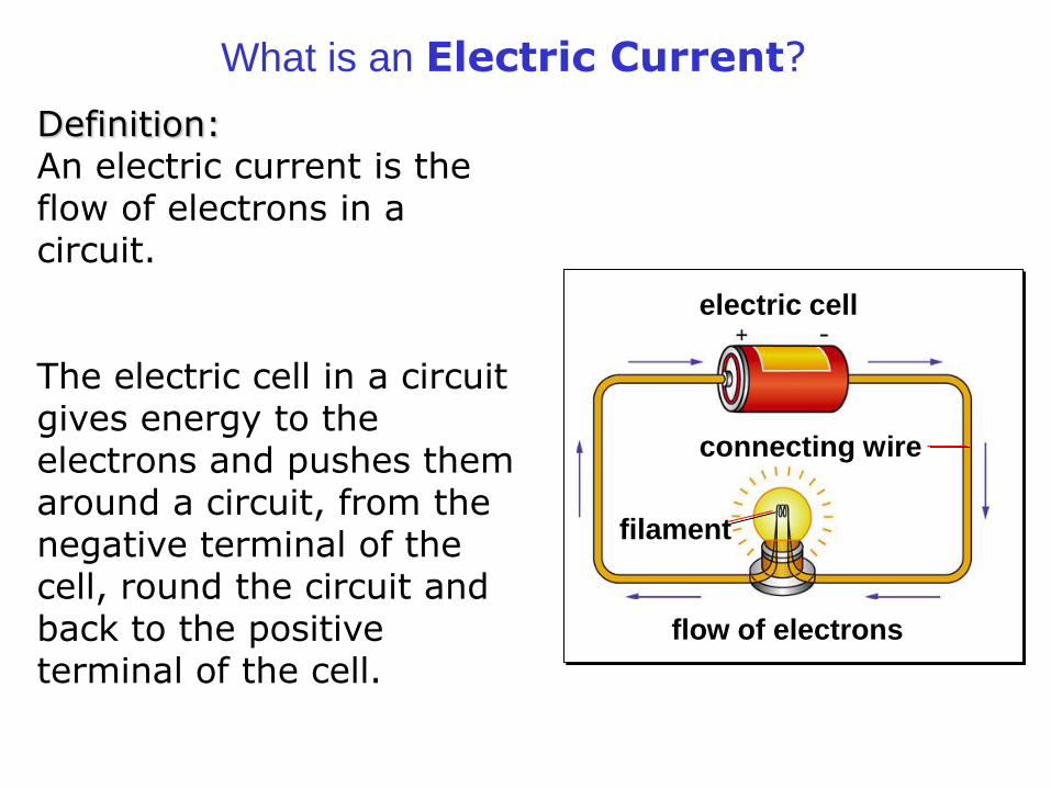
What is an Electric Current?
Definition:An electric current is the flow of electrons in a circuit.
The electric cell in a circuit gives energy to the electrons and pushes them around a circuit, from the negative terminal of the cell, round the circuit and back to the positive terminal of the cell.
connecting wire
electric cell
filament
flow of electrons
electric current
electron flow
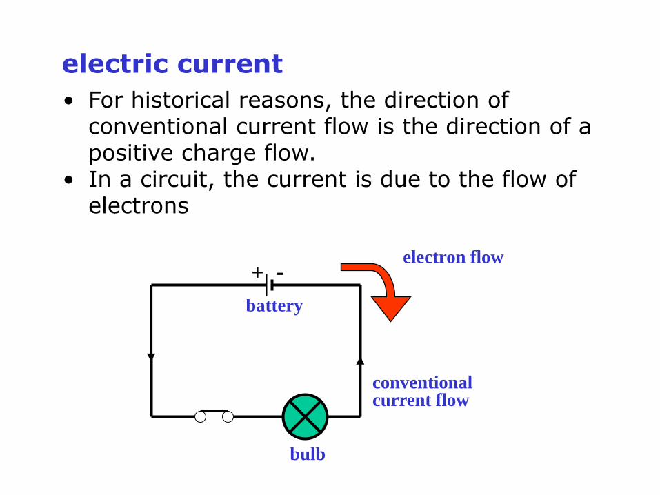
• For historical reasons, the direction of conventional current flow is the direction of a positive charge flow.
• In a circuit, the current is due to the flow of electrons
bulb
conventionalcurrent flow
battery
+ -
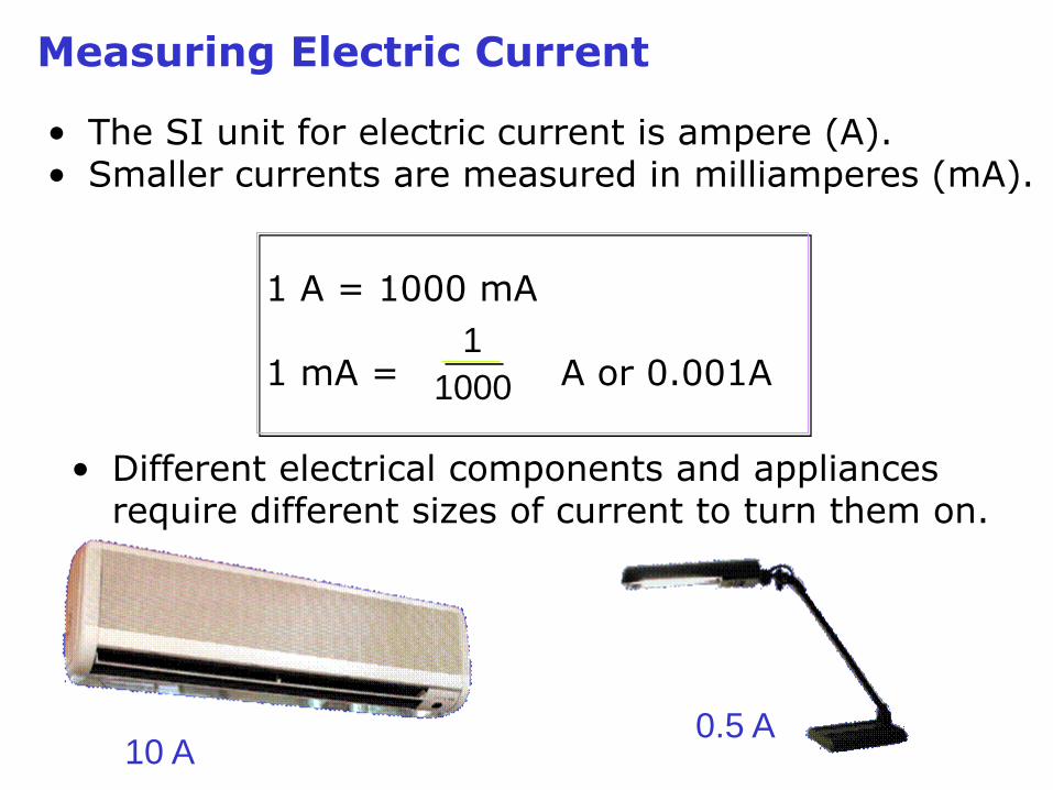
Measuring Electric Current
• The SI unit for electric current is ampere (A). • Smaller currents are measured in milliamperes (mA).
1 A = 1000 mA
1 mA = A or 0.001A1
1000
• Different electrical components and appliances require different sizes of current to turn them on.
10 A0.5 A
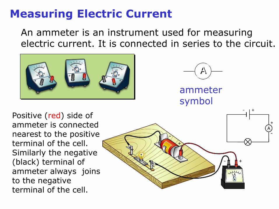
An ammeter is an instrument used for measuring electric current. It is connected in series to the circuit.
A
ammeter symbol
Positive (red) side of ammeter is connected nearest to the positive terminal of the cell. Similarly the negative (black) terminal of ammeter always joins to the negative terminal of the cell.
Measuring Electric Current
- Potential Difference
- Electromotive Force
What are they? Why the 2 names?
How are they related? How are
they different?

Electromotive Force
The electromotive force (e.m.f) of an electrical energy source is defined as the work done by the source in driving a unit charge round a complete circuit.
The SI unit for e.m.f is volt (V).
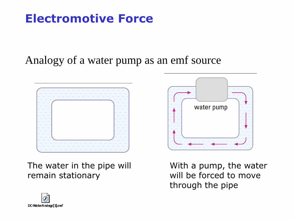
Analogy of a water pump as an emf source
The water in the pipe will remain stationary
With a pump, the water will be forced to move through the pipe
Electromotive Force
Potential Difference
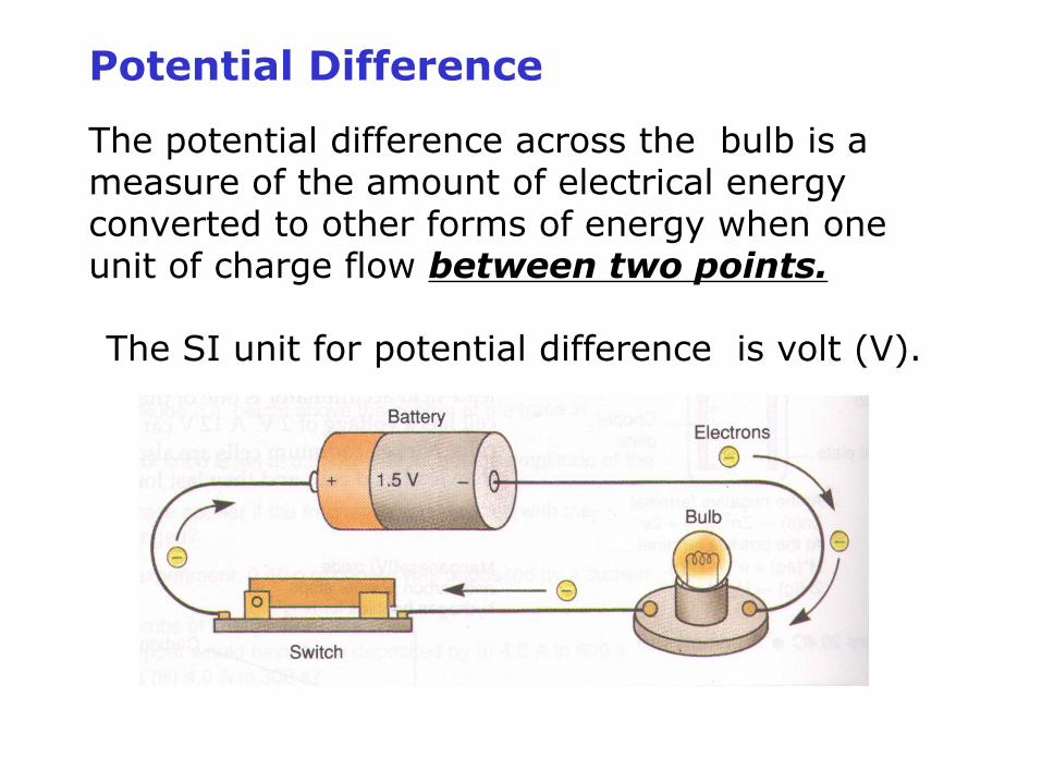
The potential difference across the bulb is a measure of the amount of electrical energy converted to other forms of energy when one unit of charge flow between two points.
The SI unit for potential difference is volt (V).
Measuring potential difference and e.m.f
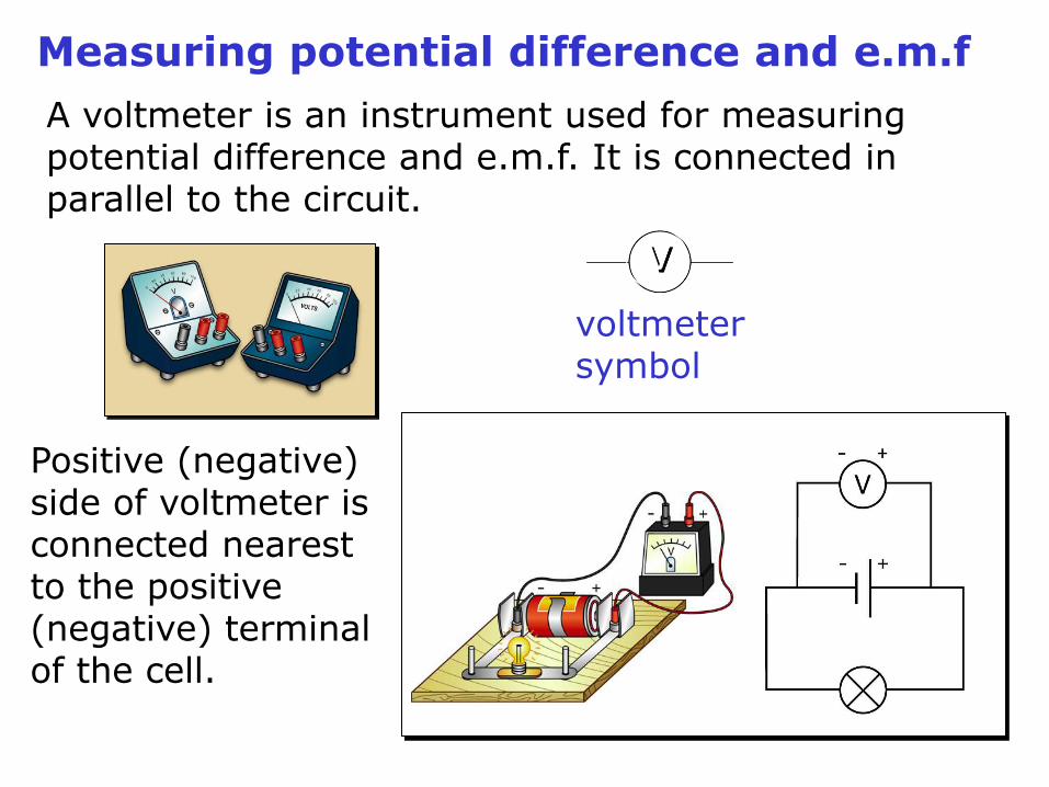
A voltmeter is an instrument used for measuring potential difference and e.m.f. It is connected in parallel to the circuit.
V
voltmeter symbol
Positive (negative) side of voltmeter is connected nearest to the positive (negative) terminal of the cell.
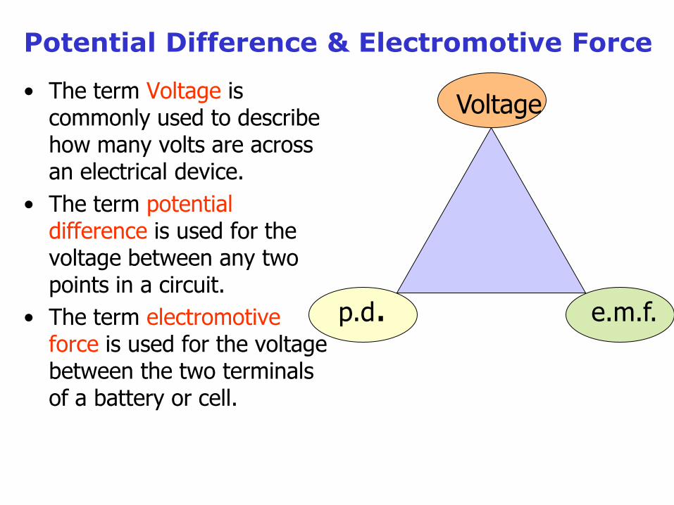
• The term Voltage is commonly used to describe how many volts are across an electrical device.
• The term potential difference is used for the voltage between any two points in a circuit.
• The term electromotive force is used for the voltage between the two terminals of a battery or cell.
Voltage
p.d. e.m.f.
Potential Difference & Electromotive Force
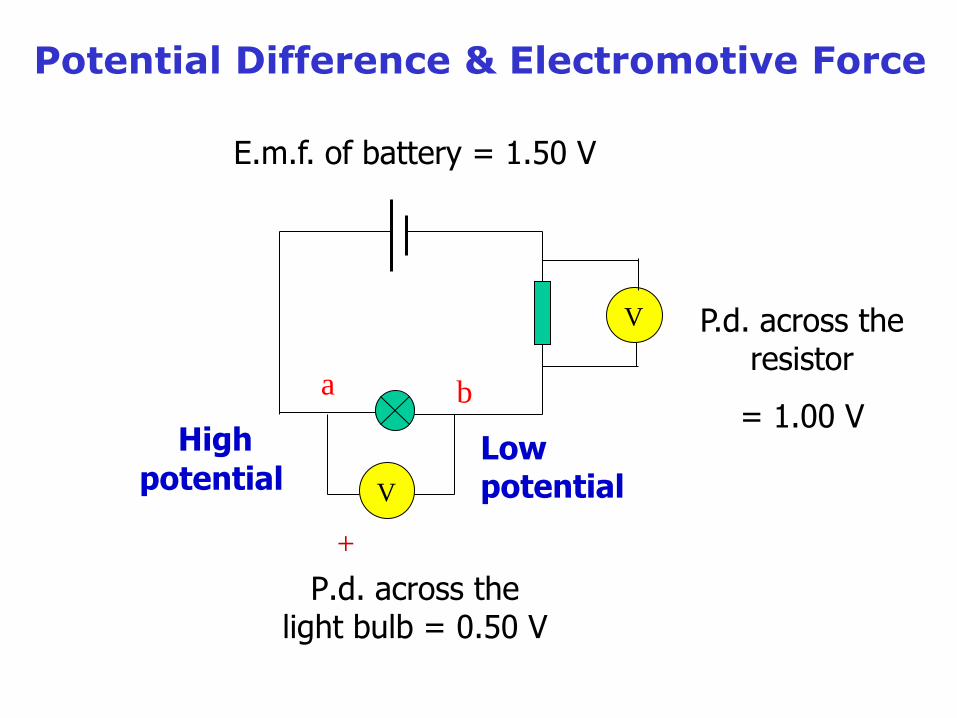
P.d. across the light bulb = 0.50 V
V
+
a b
High
potentialLow potential
V P.d. across the resistor
= 1.00 V
E.m.f. of battery = 1.50 V
Potential Difference & Electromotive Force
- How are we going to measure?
- In series?
- In parallel?
Resistance
An electric current does not always flow easily in a circuit because the circuit wires and the components resist the flow of electrons. The wire and components are said to have resistance.
The greater the resistance in a circuit, the lower the current.
Different conductors have different resistances. Resistance wires, made of nichrome have a higher resistance than copper wires.
The SI unit for resistance is the ohm ().

Resistors
An electrical component that is specially made to have a certain resistance is called a resistor. Resistors that have one fixed resistance are called fixed resistors.
fixed resistor symbol
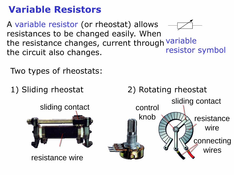
Variable Resistors
Two types of rheostats:
1) Sliding rheostat 2) Rotating rheostat
variable resistor symbol
A variable resistor (or rheostat) allows resistances to be changed easily. When the resistance changes, current through the circuit also changes.
connecting
wires
sliding contact
resistance
wire
control
knob
sliding contact
resistance wire
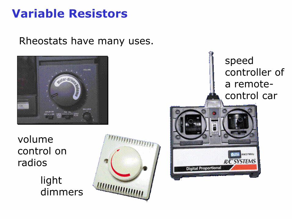
Variable Resistors
Rheostats have many uses.
volume control on radios
light dimmers
speed controller of a remote-control car
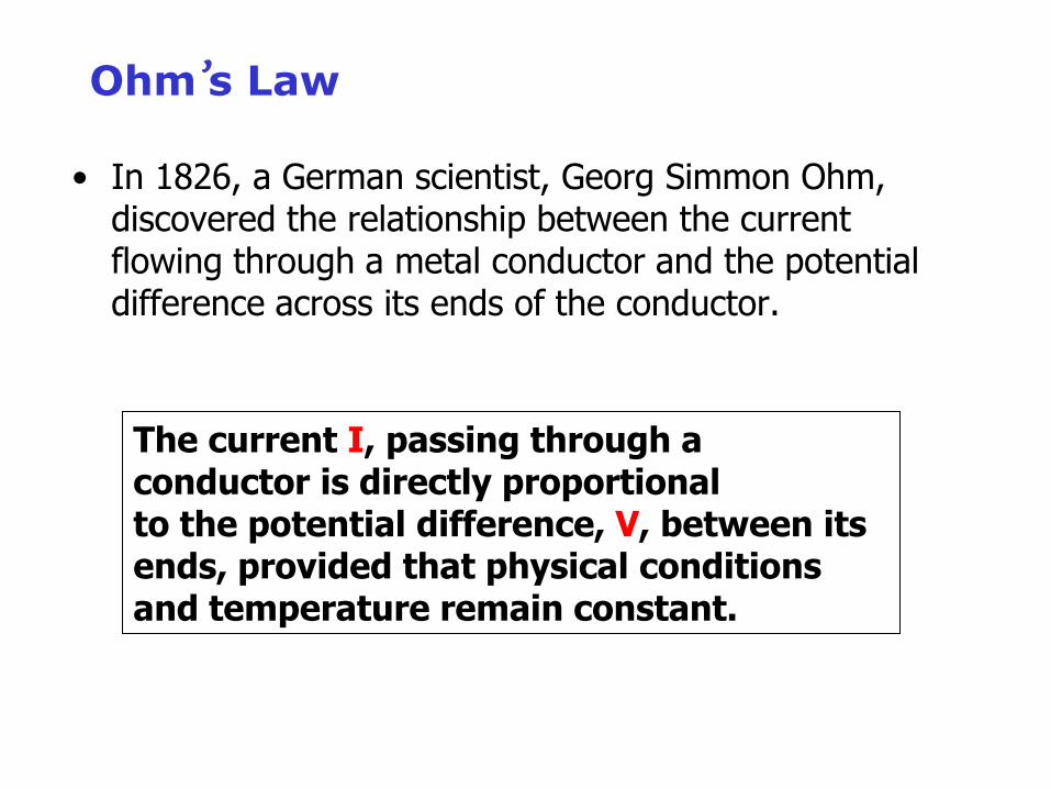
Ohm’s Law
• In 1826, a German scientist, Georg Simmon Ohm, discovered the relationship between the current flowing through a metal conductor and the potential difference across its ends of the conductor.
The current I, passing through a conductor is directly proportional to the potential difference, V, between its ends, provided that physical conditions and temperature remain constant.
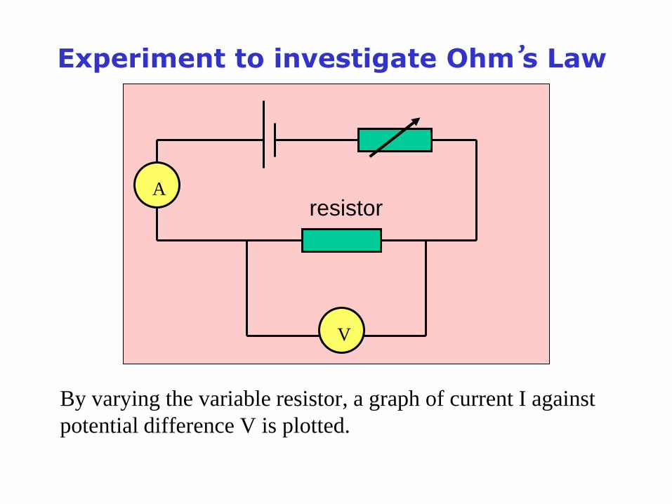
Experiment to investigate Ohm’s Law
A
V
resistor
By varying the variable resistor, a graph of current I against
potential difference V is plotted.
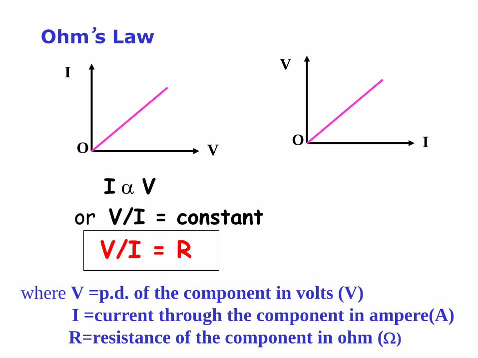
I V
or V/I = constant
V/I = R
V
IO
Ohm’s Law
where V =p.d. of the component in volts (V)
I =current through the component in ampere(A)
R=resistance of the component in ohm ()
I
VO
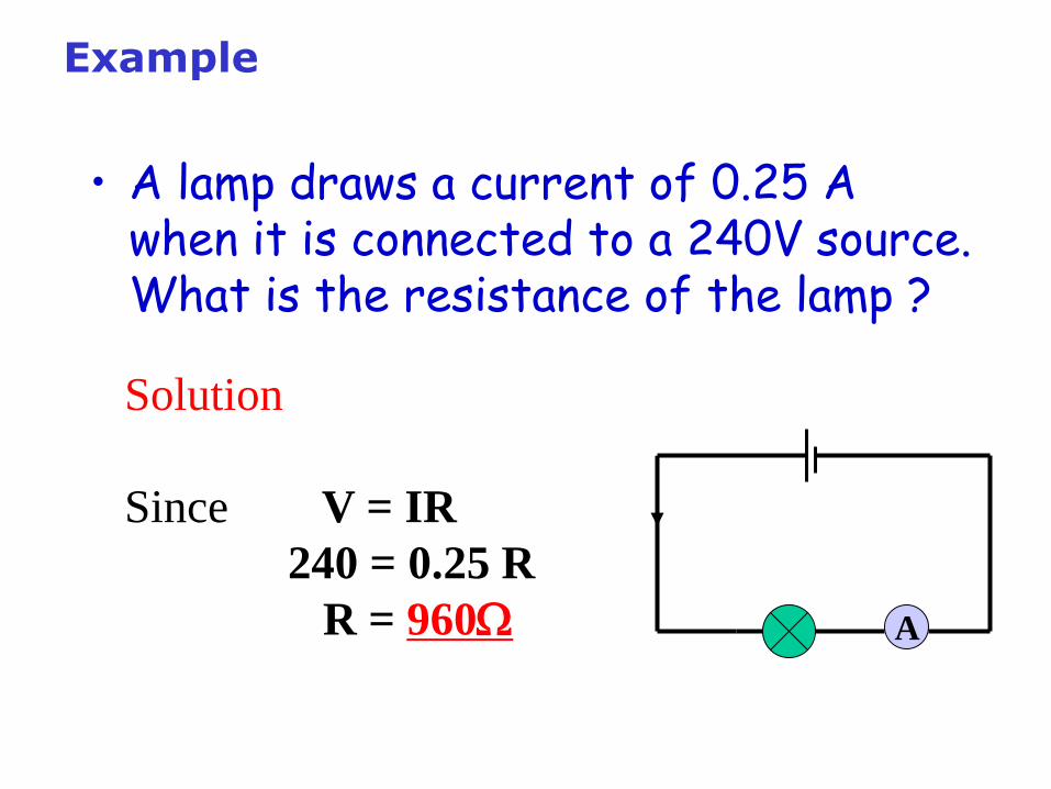
Example
• A lamp draws a current of 0.25 A when it is connected to a 240V source. What is the resistance of the lamp ?
A
Solution
Since V = IR
240 = 0.25 R
R = 960
Example
• Calculate the current flowing through a 5 resistor when the potential difference across the resistor is 2 V.
Solution
since V = IR
2 = I 5
I = 0.4 A
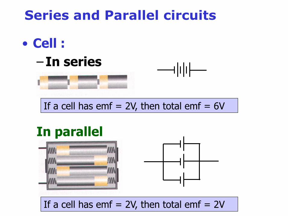
Series and Parallel circuits
• Cell :
– In series
In parallel
If a cell has emf = 2V, then total emf = 6V
If a cell has emf = 2V, then total emf = 2V
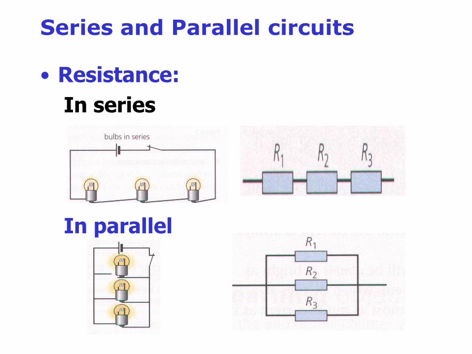
Series and Parallel circuits
• Resistance:
In series
In parallel
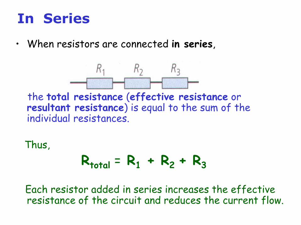
In Series
• When resistors are connected in series,
the total resistance (effective resistance or resultant resistance) is equal to the sum of the individual resistances.
Thus,
Rtotal = R1 + R2 + R3
Each resistor added in series increases the effective resistance of the circuit and reduces the current flow.
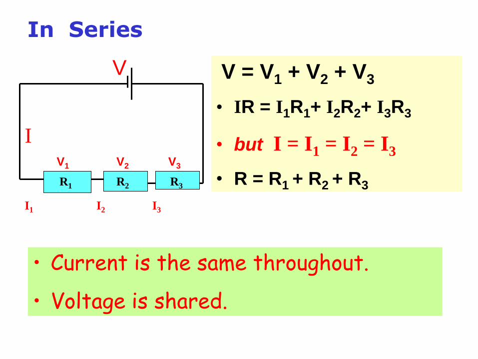
V = V1 + V2 + V3
• IR = I1R1+ I2R2+ I3R3
• but I = I1 = I2 = I3
• R = R1 + R2 + R3
V
V1 V2 V3
I
I1 I2 I3
R1 R2 R3
• Current is the same throughout.
• Voltage is shared.
In Series
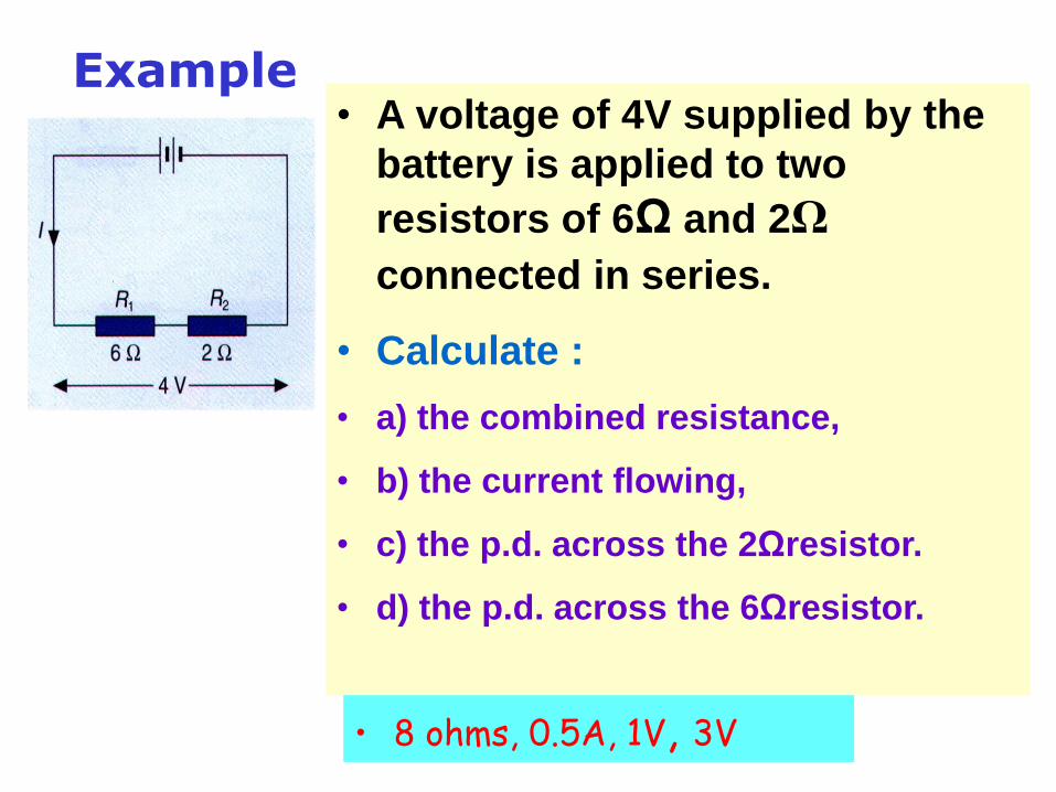
Example• A voltage of 4V supplied by the
battery is applied to two
resistors of 6Ω and 2Ω
connected in series.
• Calculate :
• a) the combined resistance,
• b) the current flowing,
• c) the p.d. across the 2Ωresistor.
• d) the p.d. across the 6Ωresistor.
• 8 ohms, 0.5A, 1V, 3V
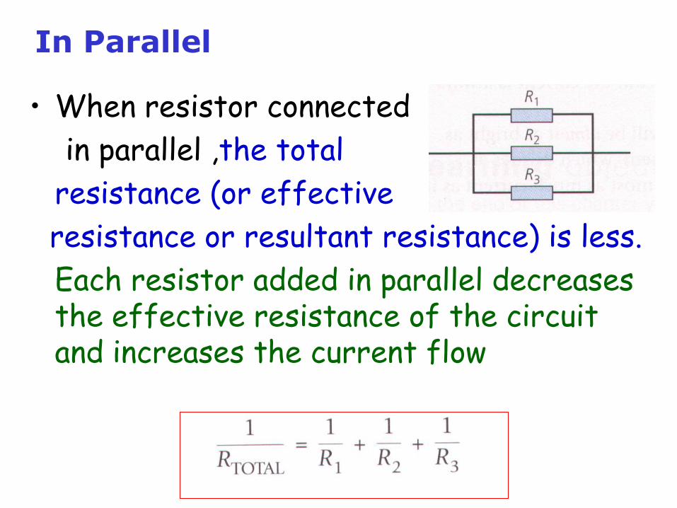
In Parallel
• When resistor connected
in parallel ,the total
resistance (or effective
resistance or resultant resistance) is less.
Each resistor added in parallel decreases the effective resistance of the circuit and increases the current flow
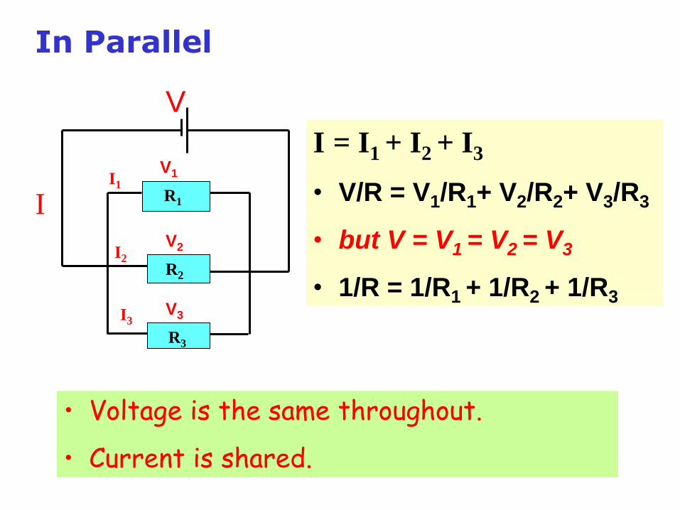
I = I1 + I2 + I3
• V/R = V1/R1+ V2/R2+ V3/R3
• but V = V1 = V2 = V3
• 1/R = 1/R1 + 1/R2 + 1/R3
V
V1
V2
V3
II1
I2
I3
R1
R2
R3
• Voltage is the same throughout.
• Current is shared.
In Parallel
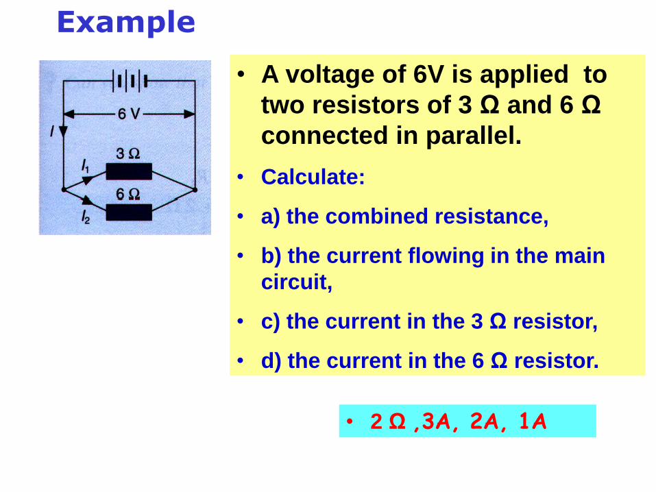
Example
• A voltage of 6V is applied to
two resistors of 3 Ω and 6 Ω
connected in parallel.
• Calculate:
• a) the combined resistance,
• b) the current flowing in the main
circuit,
• c) the current in the 3 Ω resistor,
• d) the current in the 6 Ω resistor.
• 2 Ω ,3A, 2A, 1A
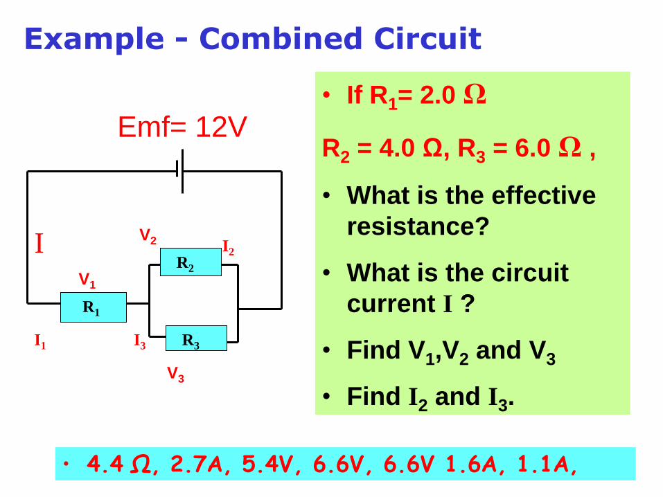
Example - Combined Circuit
Emf= 12V
V1
V2
V3
I
I1 I3
I2
R1
R2
R3
• If R1= 2.0 Ω
R2 = 4.0 Ω, R3 = 6.0 Ω ,
• What is the effective
resistance?
• What is the circuit
current I ?
• Find V1,V2 and V3
• Find I2 and I3.
• 4.4 Ω, 2.7A, 5.4V, 6.6V, 6.6V 1.6A, 1.1A,
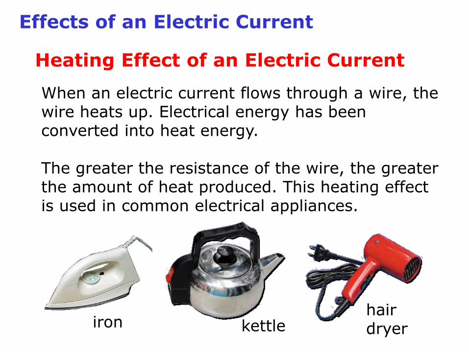
Effects of an Electric Current
Heating Effect of an Electric Current
When an electric current flows through a wire, the wire heats up. Electrical energy has been converted into heat energy.
The greater the resistance of the wire, the greater the amount of heat produced. This heating effect is used in common electrical appliances.
iron kettlehair dryer
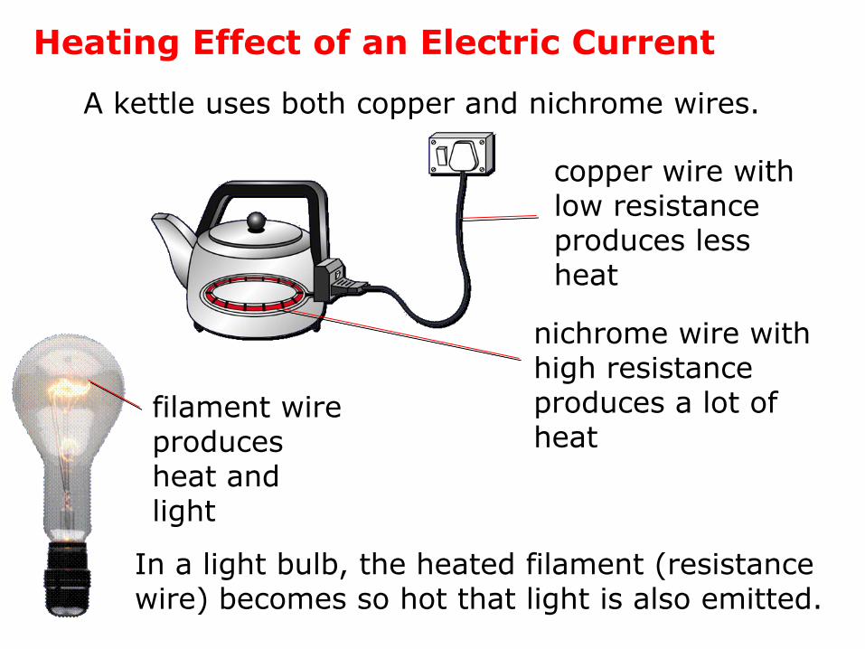
Heating Effect of an Electric Current
A kettle uses both copper and nichrome wires.
In a light bulb, the heated filament (resistance wire) becomes so hot that light is also emitted.
copper wire with low resistance produces less heat
nichrome wire with high resistance produces a lot of heat
filament wire produces heat and light
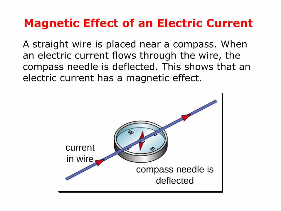
Magnetic Effect of an Electric Current
A straight wire is placed near a compass. When an electric current flows through the wire, the compass needle is deflected. This shows that an electric current has a magnetic effect.
compass needle is
deflected
current
in wire
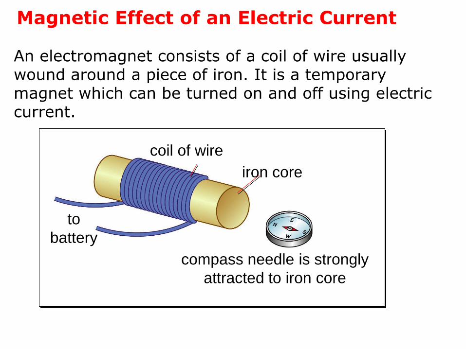
Magnetic Effect of an Electric Current
An electromagnet consists of a coil of wire usually wound around a piece of iron. It is a temporary magnet which can be turned on and off using electric current.
coil of wire
to
battery
iron core
compass needle is strongly
attracted to iron core
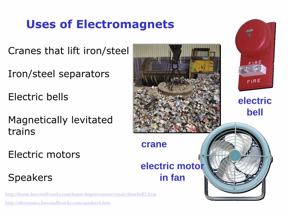
Uses of Electromagnets
Cranes that lift iron/steel
Iron/steel separators
Electric bells
Magnetically levitated trains
Electric motors
Speakers
electric
bell
crane
electric motor
in fan
http://home.howstuffworks.com/home-improvement/repair/doorbell3.htm
http://electronics.howstuffworks.com/speaker6.htm

Uses of Electromagnets
Shanghai's flashy new Maglev, the world's fastest train.
The train can reach almost 322 km/h in 2 min, with a maximum speed of 430 km/h.
http://www.youtube.com/watch?v=IT-mVT-ORww
Chemical Effect of an Electric Current
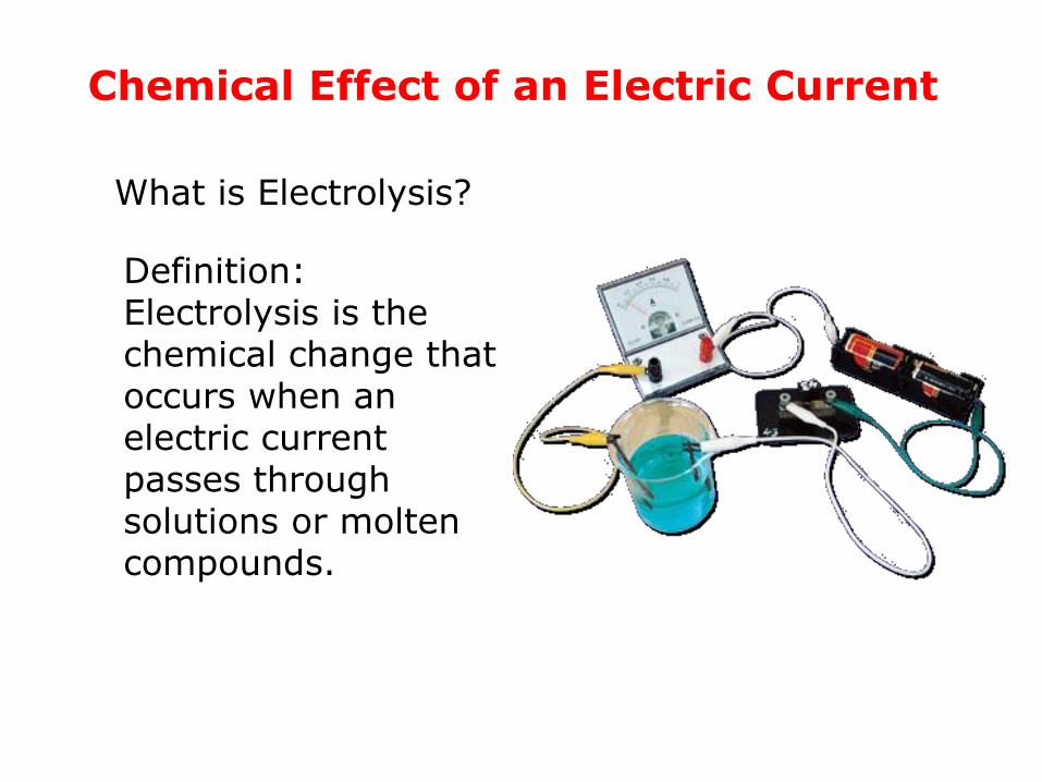
Definition:Electrolysis is the chemical change that occurs when an electric current passes through solutions or molten compounds.
What is Electrolysis?
Chemical Effect of an Electric Current
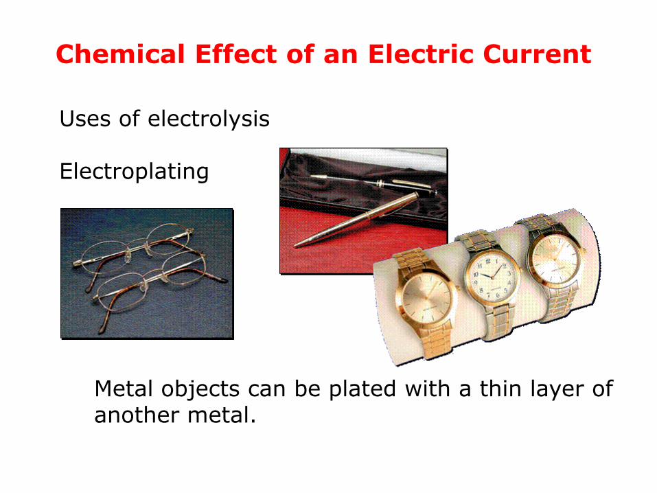
Uses of electrolysis
Electroplating
Metal objects can be plated with a thin layer of another metal.
Chemical Effect of an Electric Current
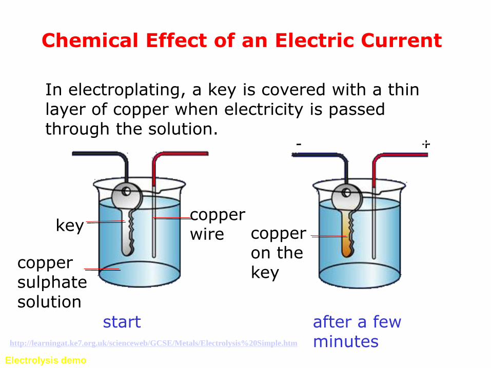
keycopper wire
copper sulphate solution
copper on the key
+-
In electroplating, a key is covered with a thin layer of copper when electricity is passed through the solution.
start after a few minutes
Electrolysis demo
http://learningat.ke7.org.uk/scienceweb/GCSE/Metals/Electrolysis%20Simple.htm


