Embed Size (px)
Citation preview

UNIT - 3
COMPUTER NETWORKS

Flow Control• Ensuring the sending entity does not
overwhelm the receiving entity.– Preventing buffer overflow.
• Transmission time:– Time taken to emit all bits into medium.
• Propagation time.– Time for a bit to traverse the link.

Model of Frame Transmission

Stop and Wait
• Source transmits frame.• Destination receives frame and replies
with acknowledgement.• Source waits for ACK before sending next
frame.• Destination can stop flow by not send
ACK.• Works well for a few large frames.

Fragmentation• Large block of data may be split into small
frames : Limited buffer size.Errors detected sooner (when whole frame
received).On error, retransmission of smaller frames is
needed.Prevents one station occupying medium for long
periods.
• Stop and wait becomes inadequate.

Sliding Windows Flow Control
• Allow multiple frames to be in transit.• Receiver has buffer W long.• Transmitter can send up to W frames without
ACK.• Each frame is numbered.• ACK includes number of next frame expected.• Sequence number bounded by size of field (k).
– Frames are numbered modulo 2k.

Sliding Window Diagram

Example Sliding Window

Sliding Window Enhancements
• Receiver can acknowledge frames without permitting further transmission (Receive Not Ready).
• Must send a normal acknowledge to resume.• If duplex, use piggybacking:
If no data to send, use acknowledgement frame.If data but no acknowledgement to send, send last
acknowledgement number again, or have ACK valid flag (TCP).

Error Detection• Additional bits added by transmitter for
error detection code.
• Parity:Value of parity bit is such that character has
even (even parity) or odd (odd parity) number of ones.
Even number of bit errors goes undetected.

Cyclic Redundancy Check
• For a block of k bits transmitter generates n bit sequence.
• Transmit k+n bits which is exactly divisible by some number.
• Receive divides frame by that number:If no remainder, assume no error.

Error Control
• Detection and correction of errors.• Lost frames.• Damaged frames.• Automatic repeat request:
Error detection.Positive acknowledgment.Retransmission after timeout.Negative acknowledgement and
retransmission.

Automatic Repeat Request (ARQ)
• Stop and wait.• Go back N.• Selective reject (selective
retransmission).

Stop and Wait• Source transmits single frame.• Wait for ACK.• If received frame damaged, discard it:
Transmitter has timeout. If no ACK within timeout, retransmit.
• If ACK damaged,transmitter will not recognize it:Transmitter will retransmit.Receive gets two copies of frame.Use ACK0 and ACK1.

Stop and Wait -Diagram

Stop and Wait – Pros and Cons
• Simple.
• Inefficient.

Go Back N (1)
• Based on sliding window.• If no error, ACK as usual with next frame
expected.• Use window to control number of outstanding
frames.• If error, reply with rejection:
Discard that frame and all future frames until error frame received correctly.
Transmitter must go back and retransmit that frame and all subsequent frames.

Go Back N - Damaged Frame
• Receiver detects error in frame I.• Receiver sends rejection-I.• Transmitter gets rejection-I.• Transmitter retransmits frame i and all
subsequent.

Go Back N - Lost Frame (1)
• Frame i lost.• Transmitter sends i+1.• Receiver gets frame i+1 out of sequence.• Receiver send reject I.• Transmitter goes back to frame i and
retransmits.

Go Back N - Lost Frame (2)
• Frame i lost and no additional frame sent.• Receiver gets nothing and returns neither
acknowledgement nor rejection.• Transmitter times out and sends
acknowledgement frame with P bit set to 1.• Receiver interprets this as command which it
acknowledges with the number of the next frame it expects (frame i ).
• Transmitter then retransmits frame I.

Go Back N - Damaged Acknowledgement
• Receiver gets frame i and send acknowledgement (i+1) which is lost.
• Acknowledgements are cumulative, so next acknowledgement (i+n) may arrive before transmitter times out on frame I.
• If transmitter times out, it sends acknowledgement with P bit set as before.
• This can be repeated a number of times before a reset procedure is initiated.

Go Back N - Damaged Rejection
• As for lost frame (2)

Go Back N - Diagram

Selective Reject• Also called selective retransmission.• Only rejected frames are retransmitted.• Subsequent frames are accepted by the
receiver and buffered.• Minimizes retransmission.• Receiver must maintain large enough
buffer.• More complex login in transmitter.

Selective Reject -
Diagram

High Level Data Link Control
• HDLC.
• ISO 33009, ISO 4335.

HDLC Station Types• Primary station:
Controls operation of link.Frames issued are called commands.Maintains separate logical link to each
secondary station.• Secondary station:
Under control of primary station.Frames issued called responses.
• Combined station:May issue commands and responses.

HDLC Link Configurations
• Unbalanced:– One primary and one or more secondary stations.– Supports full duplex and half duplex.
• Balanced:– Two combined stations.– Supports full duplex and half duplex.

HDLC Transfer Modes (1)
• Normal Response Mode (NRM).– Unbalanced configuration.– Primary initiates transfer to secondary.– Secondary may only transmit data in
response to command from primary.– Used on multi-drop lines.– Host computer as primary.– Terminals as secondary.

HDLC Transfer Modes (2)
• Asynchronous Balanced Mode (ABM):Balanced configuration.Either station may initiate transmission
without receiving permission.Most widely used.No polling overhead.

HDLC Transfer Modes (3)
Asynchronous Response Mode (ARM):
Unbalanced configuration.Secondary may initiate transmission without
permission form primary.Primary responsible for line.rarely used.

Frame Structure
Synchronous transmission.All transmissions in frames.Single frame format for all data and
control exchanges.

Frame Structure Diagram

Flag Fields• Delimit frame at both ends.• 01111110.• May close one frame and open another.• Receiver hunts for flag sequence to synchronize.• Bit stuffing used to avoid confusion with data
containing 01111110:0 inserted after every sequence of five 1s If receiver detects five 1s it checks next bit If 0, it is deleted If 1 and seventh bit is 0, accept as flag If sixth and seventh bits 1, sender is indicating abort
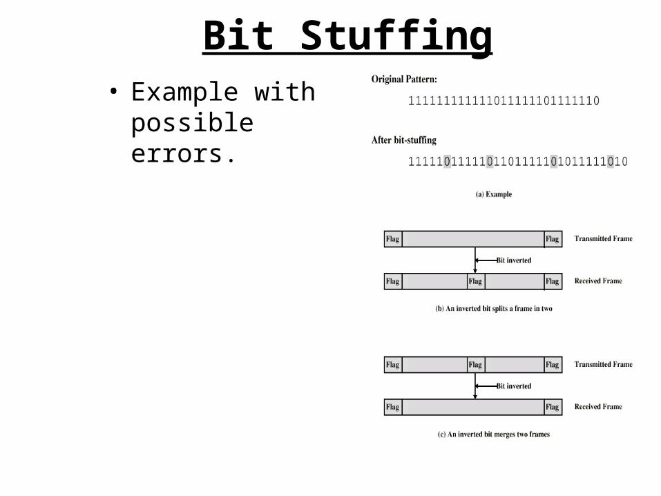
Bit Stuffing• Example with
possible errors.

Address Field• Identifies secondary station that sent or will
receive frame.• Usually 8 bits long.• May be extended to multiples of 7 bits
– LSB of each octet indicates that it is the last octet (1) or not (0).
• All ones (11111111) is broadcast.

Control Field• Different for different frame type:
Information - data to be transmitted to user (next layer up). Flow and error control piggybacked on information
frames. Supervisory - ARQ when piggyback not used.Unnumbered - supplementary link control.
• First one or two bits of control filed identify frame type.
• Remaining bits explained later.

Control Field Diagram

Poll/Final Bit• Use depends on context.• Command frame:
– P bit.– 1 to solicit (poll) response from peer.
• Response frame:– F bit.– 1 indicates response to soliciting command.

Information Field
• Only in information and some unnumbered frames.
• Must contain integral number of octets.• Variable length.

Frame Check Sequence Field
• FCS.• Error detection.

HDLC Operation
• Exchange of information, supervisory and unnumbered frames.
• Three phases:Initialization.Data transfer.Disconnect.

Other DLC Protocols (LAPB,LAPD)• Link Access Procedure, Balanced (LAPB):
Part of X.25 (ITU-T). Subset of HDLC – ABM.Point to point link between system and packet
switching network node.• Link Access Procedure, D-Channel:
ISDN (ITU-D).ABM.Always 7-bit sequence numbers (no 3-bit).16 bit address field contains two sub-addresses.
• One for device and one for user (next layer up).

Other DLC Protocols (LLC)
• Logical Link Control (LLC): IEEE 802.Different frame format. Link control split between medium access layer
(MAC) and LLC (on top of MAC).No primary and secondary - all stations are peers.Two addresses needed.
• Sender and receiver.Error detection at MAC layer.
• 32 bit CRC.Destination and source access points (DSAP, SSAP).

Other DLC Protocols (Frame Relay) (1)
• Streamlined capability over high speed packet witched networks.
• Used in place of X.25.• Uses Link Access Procedure for Frame-
Mode Bearer Services (LAPF).• Two protocols:
Control - similar to HDLC.Core - subset of control.

Other DLC Protocols (Frame Relay) (2)
• ABM.• 7-bit sequence numbers.• 16 bit CRC.• 2, 3 or 4 octet address field:
Data link connection identifier (DLCI). Identifies logical connection.
• More on frame relay later.

Switching Networks
• Long distance transmission is typically done over a network of switched nodes
• Nodes not concerned with content of data• End devices are stations
– Computer, terminal, phone, etc.• A collection of nodes and connections is a
communications network• Data routed by being switched from node to
node

Nodes
• Nodes may connect to other nodes only, or to stations and other nodes
• Node to node links usually multiplexed• Network is usually partially connected
– Some redundant connections are desirable for reliability
• Two different switching technologies– Circuit switching– Packet switching
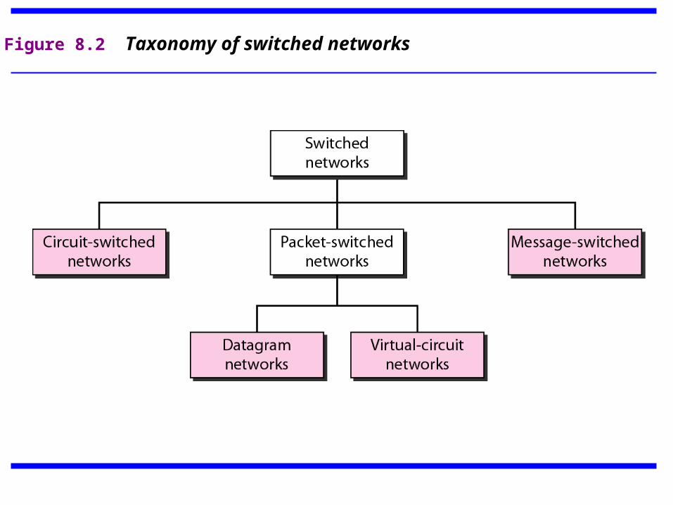
Figure 8.2 Taxonomy of switched networks

Circuit Switching
• Dedicated communication path between two stations
• Three phases– Establish– Transfer– Disconnect
• Must have switching capacity and channel capacity to establish connection
• Must have intelligence to work out routing

Circuit Switching - Applications
• Inefficient– Channel capacity dedicated for duration of
connection– If no data, capacity wasted
• Set up (connection) takes time• Once connected, transfer is transparent• Developed for voice traffic (phone)

Public Circuit Switched Network

Circuit Establishment

Circuit Switching Principles revisited
• Circuit switching designed for voice– Resources dedicated to a particular call– Much of the time a data connection is idle– Data rate is fixed
• Both ends must operate at the same rate

Call blocking
• Can’t find a path from input to output• Internal blocking
– slot in output frame exists, but no path
• Output blocking– no slot in output frame is available

Message Switching
• With message switching there is no need to establish a dedicated path between two stations.
• When a station sends a message, the destination address is appended to the message.
• The message is then transmitted through the network, in its entirety, from node to node.
• Each node receives the entire message, stores it in its entirety on disk, and then transmits the message to the next node.
• This type of network is called a store-and-forward network.

Message Switching
A message-switching node is typically a general-purpose computer. The device needs sufficient secondary-storage capacity to store the incoming messages, which could be long. A time delay is introduced using this type of scheme due to store- and-forward time, plus the time required to find the next node in the transmission path.

Message Switching
Advantages: • Channel efficiency can be greater compared to circuit- switched systems, because more devices are sharing the channel. • Traffic congestion can be reduced, because messages may be temporarily stored in route. • Message priorities can be established due to store-and-forward technique. • Message broadcasting can be achieved with the use of broadcast address appended in the message.

Message Switching
Disadvantages • Message switching is not compatible with interactive applications. • Store-and-forward devices are expensive, because they must have large disks to hold potentially long messages.

Packet Switching: Basic Operation
• Data transmitted in small packets– Longer messages split into series of packets– Each packet contains a portion of user data plus
some control info• Control info
– Routing (addressing) info• Packets are received, stored briefly (buffered)
and past on to the next node– Store and forward

Packet-Switched Network

Use of Packets

Advantages
• Line efficiency– Single node to node link can be shared by many packets over time– Packets queued and transmitted as fast as possible
• Data rate conversion– Each station connects to the local node at its own speed– Nodes buffer data if required to equalize rates
• Packets are accepted even when network is busy– Delivery may slow down
• Priorities can be used

Switching Technique
• Station breaks long message into packets• Packets sent one at a time to the network• Packets handled in two ways
– Datagram– Virtual circuit

Datagram
• Each packet treated independently• Packets can take any practical route• Packets may arrive out of order• Packets may go missing• Up to receiver to re-order packets and recover
from missing packets

DatagramDiagram

67
Virtual Circuit
• In virtual circuit, a preplanned route is established before any packets are sent, then all packets follow the same route.
• Each packet contains a virtual circuit identifier instead of destination address, and each node on the preestablished route knows where to forward such packets.– The node need not make a routing decision for each
packet.• Example: X.25, Frame Relay, ATM

68
VirtualCircuit
A route between stations is set up prior to data transfer.
All the data packets then follow the same route.
But there is no dedicated resources reserved for the virtual circuit! Packets need to be stored-and-forwarded.

69
Virtual Circuits v Datagram• Virtual circuits
– Network can provide sequencing (packets arrive at the same order) and error control (retransmission between two nodes).
– Packets are forwarded more quickly• Based on the virtual circuit identifier• No routing decisions to make
– Less reliable• If a node fails, all virtual circuits that pass through that node fail.
• Datagram– No call setup phase
• Good for bursty data, such as Web applications– More flexible
• If a node fails, packets may find an alternate route• Routing can be used to avoid congested parts of the network


Comparison of communication
switching techniques

Classification
• Packet vs. circuit switches– packets have headers and samples don’t
• Connectionless vs. connection oriented– connection oriented switches need a call setup– setup is handled in control plane by switch
controller– connectionless switches deal with self-contained
datagrams
Connectionless(router)
Connection-oriented(switching system)
Packetswitch
Internet router ATM switching system
Circuitswitch
Telephone switchingsystem

Requirements• Capacity of switch is the maximum rate at which it can
move information, assuming all data paths are simultaneously active
• Primary goal: maximize capacity– subject to cost and reliability constraints
• Circuit switch must reject call if can’t find a path for samples from input to output– goal: minimize call blocking
• Packet switch must reject a packet if it can’t find a buffer to store it awaiting access to output trunk– goal: minimize packet loss
• Don’t reorder packets

Blocking in packet switches
• Can have both internal and output blocking• Internal
– no path to output• Output
– trunk unavailable• Unlike a circuit switch, cannot predict if
packets will block (why?)• If packet is blocked, must either buffer or drop
it

Dealing with blocking
• Overprovisioning– internal links much faster than inputs
• Buffers– at input or output
• Backpressure– if switch fabric doesn’t have buffers, prevent
packet from entering until path is available• Parallel switch fabrics
– increases effective switching capacity

What Is ISDN?

ISDN Benefits• Carries a variety of user traffic, such as digital
video, data, and telephone network services, using the normal phone circuit-switched network
• Offers much faster call setup than modems by using out-of-band signaling (D channel)– Often less than one second
• Provides a faster data transfer rate than modems by using the 64-kbps bearer channel (B channel)– Can combine multiple B channels to bandwidth of
128 kbps• Can negotiate PPP links

ISDN Devices• Terminal Adapter (TA) - Converter device that converts standard
electrical signals into the form used by ISDN - allows non-ISDN devices to operate on an ISDN network.
• Terminal Equipment Type 1 (TE1) - Compatible with the ISDN network. Example:Telephones, personal computers, fax machine or videoconferencing machine.
• Terminal Equipment Type 2 (TE2) - Not compatible with the ISDN network. Example: Analog phone or modem, requires a TA (TE2 connects to TA).
• Network termination type 1 & 2 (NT1 and NT2) - A small connection box that physically connects the customer site to the telco local loop, provides a four-wire connection to the customer site and a two-wire connection to the network (PRI – CSU/DSU).

ISDN Components and Reference Points

ISDN Reference Points
• U - Two wire cable that connects the customer’s equipment to the telecommunications provider
• R - Point between non-ISDN equipment (TE2) and the TA
• S - Four-wire cable from TE1 or TA to the NT1 or NT2
• T - Point between NT1 and NT2

Analogies• NT-1 (Network Terminator-1)
– An NT-1 is an interface box that converts ISDN data into something a PC can understand (and vice versa). It works a little like a cable TV descrambler for ISDN signals, and is often built into ISDN adapters.
• TA (Terminal Adapter)– This chunk of hardware converts the data it receives
over ISDN to a form your computer can understand. Sometimes mistakenly called an ISDN modem or a digital modem, a terminal adapter handles data digitally and does not need to modulate or demodulate an analog signal. Terminal adapters can be an internal board or an external board that connects to the computer through the serial port.

ISDN Components and Reference Points #2

ISDN Reference Points

ISDN and the OSI Reference Model
• The ISDN Physical Layer• The ISDN Data Link Layer• The ISDN Network Layer

ITU-T Standards of the First Three Layers of ISDN

ISDN Protocols• E-series protocols—Telephone network
standards for ISDN.• I-series protocols—Specify ISDN concepts
and interfaces.• Q-series protocols—Standards for ISDN
switching and signaling.• Operate at the physical, data link, and
network layers of the OSI reference model

ISDN Protocol Operating OSI Layers 1 Through 3
• Physical layer ISDN protocols– BRI (ITU-T I.430) / PRI (ITU-T I.431)
• Defines two ISDN physical layer frame formats– Inbound (local exchange to ISDN customer)– Outbound (ISDN customer to local exchange )
• Data link layer ISDN protocols– LAPD signaling protocol (ITU-T Q.920 for BRI and Q.921 for PRI) for transmitting
control and signaling information over the D channel • LAPD frame format similar to ISO HDLC frame format
• Network layer ISDN protocols– ITU-T I.930 and ITU-T Q.931 defines switching and signaling methods using the D
channel.
Note: With Q.921/Q.931 the second digit indicates the OSI layer.

ISDN Physical Layer
ISDN physical-layer frame formats are 48 bits long, of which 36 bits represent data

ISDN Data Link Layer
Frame format is very similar to that of HDLC

ISDN Network Layer • Two Layer 3 specifications are used for
ISDN signaling: – ITU-T I.450 (also known as ITU-T Q.930)– ITU-T I.451 (also known as ITU-T Q.931)– Together, these protocols support:
• User-to-user circuit-switched connections• User-to-user packet-switched connections• A variety of standards for:
– Call establishment– Call termination
ISDN Encapsulation
• The two most common encapsulations:– PPP– HDLC
• ISDN defaults to HDLC.• PPP is much more robust.
– Open standard specified by RFC 1661 – Supported by most vendors

ISDN Uses
• Remote Access (Telecommuters)• Remote Nodes (Voice and Data)• SOHO Connectivity (Small Branches)

Remote Access (Telecommuters)

Remote Nodes (Voice and Data)
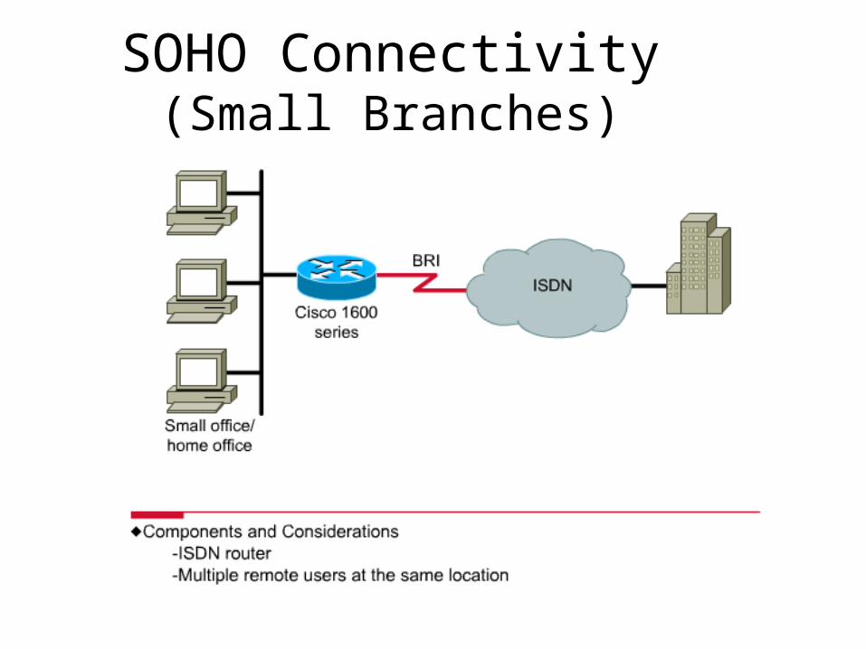
SOHO Connectivity(Small Branches)

ISDN BRI

ISDN Services – BRI• Basic Rate Interface (BRI)
– Two 64 Kbps B channels, one 16 Kbps D channel, and 48 Kbps worth of framing and synchronization.
– Available data bandwidth: 128 Kbps (2 x 64 Kbps)– User bandwidth: 144 Kbps (128 Kbps + a 16 Kbps D channel)– Total line capacity: 192 Kbps (144 Kbps + 48 Kbps framing)
• Each B channel can be used for separate applications– Such as Internet and Voice
• Allows individual B channels to be aggregated together into a Multilink channel

ISDN Services – PRI • Primary Rate Interface (PRI)
– A PRI connection can assign various 64 Kbps channels to both ISDN and analog modem connections
– North America and Japan – PRI service has 23 64 Kbps B channels, one 64 Kbps D channel, and 8 Kbps of synchronization and framing for a total bit rate of up to 1.544 Mbps (same as T1)
– Europe, Australia, and other parts of the world – PRI service has 30 64 Kbps B channels, one 64 Kbps D channel, and 64 Kbps of framing and synchronization for a total bit rate of up to 2.048 Mbps (same as E1)
• Each B channel to be used for separate applications including voice, data and Internet
• Multiple B channels can be Multilinked together

ISDN BRI ConfigurationThree Basic Steps
1. Set the ISDN Switch Type.2. Set the SPIDs (If Required).3. Set the Encapsulation Protocol.

ISDN Global and Interface Configuration Tasks

ISDN Physical Interface Diagram

ISDN Physical Interface
• Connection between terminal equipment (c.f. DTE) and network terminating equipment (c.f. DCE).
• ISO 8877.• Cables terminate in matching connectors
with 8 contacts.• Transmit/receive carry both data and
control.

ISDN Electrical Specification
• Balanced transmission: Carried on two lines, e.g. twisted pair. Signals as currents down one conductor and up the
other. Differential signaling. Value depends on direction of voltage. Tolerates more noise and generates less. (Unbalanced, e.g. RS-232 uses single signal line and
ground). Data encoding depends on data rate. Basic rate 192kbps uses pseudoternary. Primary rate uses alternative mark inversion (AMI)
and B8ZS or HDB3.