Embed Size (px)
Citation preview

UniSwitch Medium Voltage Switchgear
12 kV, 17.5 kV, 24 kV, 630 A
Installation manual

8QL6ZLWFK,QVWDOODWLRQ�PDQXDO
2
UNIS 7 GB
&217(17
��� Transportation and storage ………..………………………………………………………………………… 3��� General …………….……………………………………………………………………………………… 3��� Unpacking at installation site …...………..…………………………………………………………….. 3��� Transfer of cubicles at installation site ….…………………………………………………………….. 3��� Weight …………………………….………………………………………………………………………. 4��� Temporary storage …………….………………………………………………………………………… 4
��� Erection at site ………………………………………………………………………………………………… 5��� General ……………………………………………………………………………………………………. 5��� The switchgear bed ……………………………………………………………………………………… 5��� Fastening of the switchgear to the floor ………………………………………………………………. 5��� Cubicle dimensions ……………………………………………………………………………………… 6��� Bottom dimension drawings ……………………………………………………………………………. 7��� Connecting cubicles …………………………………………………………………………………….. 9��� The busbar compartment ………………………………………………………………………………. 10��� The busbar connections ………………………………………………………………………………… 11��� Connecting the switchgear to the earth electrode …………………………………………………… 14
��� Cable arrangement …………………………………………………………………………………………… 15��� Preparation for cable installation ………………………………………………………………………. 15��� Installation of the cables ………………………………………………………………………………… 16��� Finishing of the cable installation ………………………………………………………………………. 17��� Examples …………………………………………………………………………………………………. 17
��� Mounting of equipment ……………..………………………………………………………………………… 19��� Mounting of circuit-breakers …………………………………………………………………………….. 19��� Mounting of motor operating device UEMC 40 K8_ for UES-K3/2 …………………………………. 22��� Mounting of auxiliary switches for UES-K3/2 …………………………………………………………. 23��� Mounting of position indication and operation set ……………………………………………………. 24��� Mounting of motor operating device for UES-A3M/2 ………………………………………………… 24��� Mounting of auxiliary switches for UES-A3(M)/2 …………………………………………………….. 25��� Mounting of shunt trip-coil ………………………………………………………………………………. 25��� Installing of indicating system for current transformers afterwards ………………………………… 25

8QL6ZLWFK,QVWDOODWLRQ�PDQXDO
3
UNIS 7 GB
���7UDQVSRUWDWLRQ�DQG�VWRUDJH
����*HQHUDO
UniSwitch is delivered either as single cubicles or switchgear units with a length of no more than 2,0 m. The sizeof the package depends upon the number of cubicles and has to be defined separately for each case.
The package of the switchgear is made according to ABB Transmit instruction 353 PAK 1A1.
����8QSDFNLQJ�DW�LQVWDOODWLRQ�VLWH
The switchgear can be transferred by a manual forklift or a forklift truck. The packages should be placed on asmooth base. The UniSwitch switchgear should only be installed indoors. Therefore it is important to store theswitchgear cubicles in their transportation packages as long as possible. The packages should be opened only forinspection of possible transportation damages. After the inspection the package should be restored to originalcondition.
Possible transportation damages should be reported immediately to the carrier/forwarder. If the installation of theswitchgear is made right after the delivery, the transportation packages can be removed except the plastic film ofthe cubicles, which is to be removed at the final switchgear installation site.
����7UDQVIHU�RI�FXELFOHV�DW�LQVWDOODWLRQ�VLWH
The cubicles can be transferred in a horizontal plane by a manual forklift or a forklift truck, exceptionally by meansof rolling tubes (using at least four tubes).
The switchgear cubicles are usually transferred in upright position. Leaning or overturning should be avoided. Ifnecessary single cubicles can be leaned to horizontal plane e.g. because of low door height. In such a case thecubicle has to be supported from a wide area.
If a crane is available lifting of a single cubicle is made with two lifting wire cables from the lifting lugs situated on theroof of the cubicle.
When lifting several cubicles or a whole switchgear unit (4 cubicles at the most or a maximum length of 2 m) fourlifting wires, long enough, should be used.
1RWLFH��Circuit-breaker cubicles must not be lifted with circuit-breaker installed in the cubicle.
8QL6ZLWFK,QVWDOODWLRQ�PDQXDO
4
UNIS 7 GB
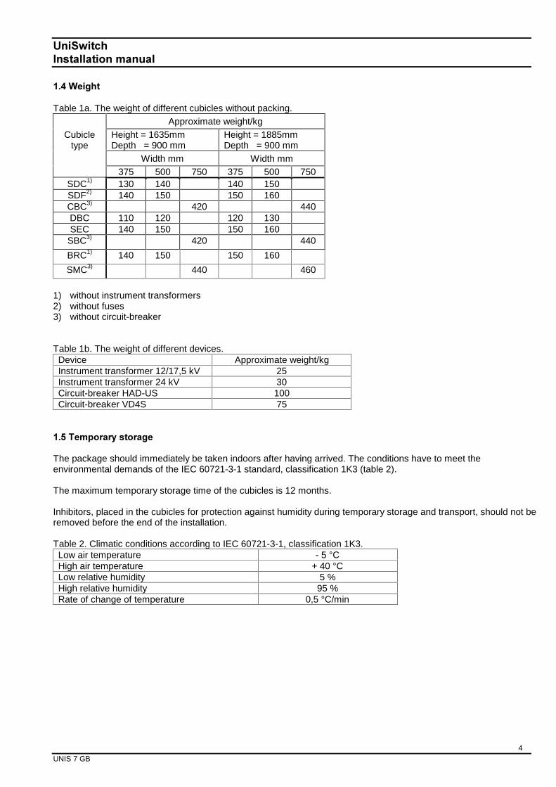
����:HLJKW
Table 1a. The weight of different cubicles without packing.Approximate weight/kg
Cubicletype
Height = 1635mmDepth = 900 mm
Height = 1885mmDepth = 900 mm
Width mm Width mm375 500 750 375 500 750
SDC1) 130 140 140 150SDF2) 140 150 150 160CBC3) 420 440DBC 110 120 120 130SEC 140 150 150 160
SBC3) 420 440
BRC1) 140 150 150 160
SMC3) 440 460
1) without instrument transformers2) without fuses3) without circuit-breaker
Table 1b. The weight of different devices.Device Approximate weight/kgInstrument transformer 12/17,5 kV 25Instrument transformer 24 kV 30Circuit-breaker HAD-US 100Circuit-breaker VD4S 75
����7HPSRUDU\�VWRUDJH
The package should immediately be taken indoors after having arrived. The conditions have to meet theenvironmental demands of the IEC 60721-3-1 standard, classification 1K3 (table 2).
The maximum temporary storage time of the cubicles is 12 months.
Inhibitors, placed in the cubicles for protection against humidity during temporary storage and transport, should not beremoved before the end of the installation.
Table 2. Climatic conditions according to IEC 60721-3-1, classification 1K3.Low air temperature - 5 °CHigh air temperature + 40 °CLow relative humidity 5 %High relative humidity 95 %Rate of change of temperature 0,5 °C/min

8QL6ZLWFK,QVWDOODWLRQ�PDQXDO
5
UNIS 7 GB
�� (UHFWLRQ�DW�VLWH
����*HQHUDO
The switchgear is to be erected on a metal frame casted in the floor of the switchgear room or on a raised floor.When preparing the floor, the demands of the DIN 43661 standard should be applied. Particularly the straightnessand uniformity of the base are important for a successful installation and should therefore be paid special attentionto.
����7KH�VZLWFKJHDU�EHG
������7KH�IORRU�RI�WKH�VZLWFKJHDU�URRP
The straightness of the floor should be ± 1 mm on the switchgear area. The load capacity of the floor should also besufficient. If the switchgear consists of only a few cubicles, and there are no heavy cubicles included, it can be in-stalled on the concrete floor.
������$�PHWDO�IUDPH�FDVWHG�LQ�WKH�IORRU
The metal frame is made of one or several parts depending of the size of the switchgear. The frame is casted in thefloor when casting the surface of the floor.
������$GMXVWPHQW�RI�WKH�FXELFOHV
There is no height adjustment of the cubicles. Adjustment is made by installing steel plates under the cubicles.
����)DVWHQLQJ�RI�WKH�VZLWFKJHDU�WR�WKH�IORRU
When designing cable ducts in the concrete floor the dimensioning drawings in chapter 2.5 should be applied.
The switchgear can be fastened to the metal frame by welding through the holes of the bottom of the cubicle (2welding seams/cubicle) or by two spline bolts/cubicle (M12) straight to the concrete floor. Fastening of a switchgearconsisting of several cubicles can be done by fastening every second cubicle.
1RWLFH� The end cubicles of the switchgear should always be fastened according to the enclosed figure.
The left-hand end cubicle is fastened from theleft-hand front and the right-hand back cornersof the cubicle floor.
The right-hand end cubicle is fastened fromthe right-hand front and left-hand backcorners.

8QL6ZLWFK,QVWDOODWLRQ�PDQXDO
6
UNIS 7 GB
����&XELFOH�GLPHQVLRQV
The following drawings illustrate the main dimensions and the need of space of different cubicle types.
Cubicle types: SDC Cubicle types: CBCSDF SMCDBC SBCBRCSEC
Table 3. Dimensions of CBC, SMC and SBC cubicles.Circuit breaker A B C DHAD-US 652 mm 215 mm 1155 mm 230 mm by
H = 1635480 mm byH = 1885
VD4S 652 mm 195 mm 1135 mm 130 mm byH = 1635
380 mm byH = 1885
There should be at least 250 mm pressure release space between the back of the switchgear and the switchgearroom wall. This space should be closed by fastening a metalsheet (thickness at least 2 mm) between the back ofthe switchgear and the wall of the switchgear room (depth 250 mm and height 1865 mm).
If the switchgear is situated in the middle of the switchgear room it has to be equipped with pressure relief channels.
940 B
C
250
1190
A
D
940
H =
163
5A
lt
H =
188
5
40
35
1000
250
1190

8QL6ZLWFK,QVWDOODWLRQ�PDQXDO
7
UNIS 7 GB
����%RWWRP�GLPHQVLRQ�GUDZLQJV
������6LQJOH�SKDVH�FDEOH
200
188
200
210
20020
500
769
85 17Ø
D =
940
W = 375 W = 500 W = 750
288
200
288
200
20
210
600
200
60
2002020
769
85
210
Ø17
500
D =
940
600
200
60
210
33
20
769
85200
33
20
500
D =
940
600
200
60
33
Ø17
W = 375 W = 500 W = 750
228
148
200
328
248
200
328
248
210
20020
500
769
85 17Ø
D =
940
20
210
600
200
60
2002020
210
769
85
210
Ø17
500
D =
940
600
200
60
210
33
20
769
85
200
33
20
500
D =
940
600
200
60
33
Ø17
210
210
210

8QL6ZLWFK,QVWDOODWLRQ�PDQXDO
8
UNIS 7 GB
��������SKDVH�FDEOH
188
200
20020
469
769
85 17Ø
D =
940
W = 375 W = 500 W = 750
288
200
288
200
20
600
200
60
2002020
769
85 Ø17
469
D =
940
600
200
60
33
20
769
85
200
33
20
469
D =
940
600
200
60
33
Ø17

8QL6ZLWFK,QVWDOODWLRQ�PDQXDO
9
UNIS 7 GB
����&RQQHFWLQJ�FXELFOHV
������&RQQHFWLQJ�FXELFOHV�LQ�WKH�FDEOH�FRPSDUWPHQW
There are four 11x20 mm holes for 1635 mm high cubicles (five holesfor 1885 mm high cubicles) in the front and back of the sidewalls forconnecting the cubicles to each other in the cable compartment.
The holes are vertical on the righthand sidewalls and horizontal on thelefthand sidewalls thus a small tolerance for erection is acceptable.
The connection is made by a 10,5 washer, a M10x20 bolt and a M10nut. The torque of the fastening bolts should be 10 Nm.
������&RQQHFWLQJ�FXELFOHV�LQ�WKH�VHFRQGDU\�FRPSDUWPHQW
In the secondary compartment the cubicles are connecting to eachother through three ∅8 holes nearest the front of the secondary com-partment. The connection is made with a 6,5 washer, a M6x20 slot-headed screw and a M6 nut. The torque of the fastening screwsshould be 5 Nm.
������&RQQHFWLRQ�RI�FXELFOHV�IURP�WKHEDFN�XSSHU�SDUW
To ensure the connection of the back upperpart of the cubicles a back up strip ofapproximately 20 cm length is mountedfrom above. The back up strip is pushedinto the seam of the back upper part of thecubicles as down as possible.

8QL6ZLWFK,QVWDOODWLRQ�PDQXDO
10
UNIS 7 GB
������&RQQHFWLRQ�RI�FXELFOHV�IURP�WKH�URRI
As a final step in connecting the cubicles to each other the roof seams between the cubicles are secured. This ismade by mounting a back up strip of the same length as the cubicle depth into the seams. The strip should bepushed so deep that the bending on the end of it touches the bottom edge of the seam. The strip must be fixed witha screw from its middle point.
����7KH�EXVEDU�FRPSDUWPHQW
The busbar compartment is covered with the top plate. The top plate isfixed to the cubicle by screws from its front and back. There are 6screws in the 375 mm wide and 8 screws in the 500 mm wide cubicle.The busbar compartment can be accessed by loosening the screwsand removing the top plate. Note that the top plates of the end cubiclesof the switchgear can not be removed.
1RWLFH� A warning sign is placed on the top plate indicating high-voltage beneath the roof.

8QL6ZLWFK,QVWDOODWLRQ�PDQXDO
11
UNIS 7 GB
����7KH�EXVEDU�FRQQHFWLRQV
The top plate of the cubicle is removed according section 2.7 before making busbar connections. The busbar con-nections in the end cubicles are made through the top openings of adjacent cubicles.
���������DQG������N9�EXVEDU�FRQQHFWLRQV
The busbars are mounted with their bended end always to the right. In the left-hand end cubicle the busbar end ismounted to the terminal of the SFG switch-disconnector. A busbar shim made of copper and with the same thick-ness as busbar, is mounted on the busbar. In the right-hand end cubicle of the switchgear the busbar shim ismounted between the bended end of the busbar and the upper terminal of the SFG switch-disconnector. The bus-bar joints are made with a 10,5 spring washer and a M10x40 hexagon head bolt. The torque of the joint is 35 Nm.
a: Hexagon head bolt M10x40b: Spring washer, hole ∅10,5c: Copper busbar shim, outer diameter ∅30, height 8 mm, hole ∅10,5d: Nonisolated 40x8 copper bar with rounded edges
���������N9�EXVEDU�FRQQHFWLRQV
24 kV busbar joints are made in the same manner as 12 and 17,5 kV busbar joints with the following exceptions.
24 kV busbars are always isolated. On the 24 kV busbar joints two-piece field control caps, consisting of aluminiumpart and EPDM-rubber part, are mounted according to the following figures.
Aluminium cap with one cutout for end cubicles. Aluminium cap with two cutouts for middle cubicles(upsidedown).
Lefthand end cubicle Middle cubicle Righthand end cubicle
a,b
c
d
d d
a,b a,bd
c

8QL6ZLWFK,QVWDOODWLRQ�PDQXDO
12
UNIS 7 GB
EPDM-rubber cap with a low cutout for lefthand EPDM-rubber cap with a high cutout for righthandend cubicles. end cubicles.
EPDM-rubber cap with two cutouts for middle cubicles(upsidedown).
a: Hexagon head bolt M10x40b: Spring washer, hole ∅10,5c: Copper raising ring, outer diameter ∅30, height 8 mm, hole ∅10,5d: Isolated 40x8 copper bar with rounded edgesf: Field control cap (aluminium and EPDM-rubber)
a,b
c
e
f
e e
f
a,ba,be
c
f
Lefthand end cubicle Middle cubicle Righthand end cubicle

8QL6ZLWFK,QVWDOODWLRQ�PDQXDO
13
UNIS 7 GB
Aluminium field control caps. Aluminium field control caps covered by EPDM- rubber caps.
������2WKHU�EXVEDU�FRQQHFWLRQV
The torque of the joint for other busbar connections is 35 Nm. Notice that the 24 kV busbar connections should becovered by a shrink tube according to the figure below. This applies also to the voltage transformer primaryconnection cable except the construction in which the connection cable is joined in a CBC-cubicle to a busbarbetween a current transformer and a fixed contact of earthing switch EM.

8QL6ZLWFK,QVWDOODWLRQ�PDQXDO
14
UNIS 7 GB
����&RQQHFWLQJ�WKH�VZLWFKJHDU�WR�WKH�HDUWK�HOHFWURGH
The earth electrode is to be connected to the main earthing bar of the cubicle (3x30 mm Cu). The connecting pointis marked with the equipment earth symbol. The connection is made with a 10,5 spring washer, M10x25 hexagonalhead bolt and a M10 hexagonal nut. The connection bolt is tightened to a torque of 40 Nm. In larger switchgears(more than 8 cubicles) the earth electrode is connected to the both end cubicles of the switchgear.
To secure the grounding via metal frame of the switchgear the main earthing bars can be connected together in thefront of cubicles using additional earthing bars (3x30 mm Cu). The connection is made with an 8,4 spring washer,M8x30 hexagonal socket-head bolt and a M8 hexagonal nut. The connection bolt is tightened to a torque of 20 Nm.
3 x 30 Cu

8QL6ZLWFK,QVWDOODWLRQ�PDQXDO
15
UNIS 7 GB
���&DEOH�DUUDQJHPHQW
����3UHSDUDWLRQ�IRU�FDEOH�LQVWDOODWLRQ
a) Remove the door from the cable compartment. Notice. The door can be opened only when the switch-disconnector is in the earthed position and the locking unit is in the ‘door open’ position.
b) Loose 4 screws from the baseboard in front of the door step of the cubicle.
c) Loose 4 screws from the door step and remove the door step from the cubicle by pushing it straight forward inits side steering tracks.

8QL6ZLWFK,QVWDOODWLRQ�PDQXDO
16
UNIS 7 GB
d) Remove the floor plates, including plastic parts, from phases L1 and L2 by pulling them forward in their sidesteering tracks.
e) Remove the front floor plate and the plastic cable sealing of phase L3. 1RWLFH� The rearmost floor plate ofphase L3 should not be removed.
����,QVWDOODWLRQ�RI�WKH�FDEOHV
Pull the cables through the open bottom into the cubicle. Measure and cut the cables to sufficient length consideringthe installation of cable terminations and cable lugs. Bend the conductors of phase L1 and L2 out through the openfront of the cubicle during the installation of the conductor of phase L3.
a) Connection of the conductor of phase L3
Take the plastic cable sealing and thread it on the conductor. Measure the right length of the cable considering theright location of the sealing. Install the necessary cable termination and clamp an appropriate cable lug to theconductor. Loose the nut and spring washer of the connector. Hang the conductor from its cable lug on the bolt ofthe connector. Install the pressure relief washer, the spring washer and the nut. Tighten the connection to suitabletightness, in the switch-disconnector and circuit-breaker cubicles 55 Nm and the fuse switch-disconnector cubicle35 Nm.
Pull the front floor plate (aluminium) in its side guides tight to the rearmost floor plate and attach them together withM6 bolts. Considering the size of the conductor, take the right size of cable clamp and attach the cable withsufficient tightness to the rearmost bushing considering the straightness of the cable from the fixture to theconnection bolt.
b) Connection of the conductor of phase L2
Pull the rearmost floor plate (steel) of phase L2 in its side guides tight to the floor bushing of phase L3. Take theprecut conductor of phase L2 and continue according to section 3.2 a.
c) Connection of the conductor of phase L1
Pull the rearmost floor plate (steel) of phase L1 in its side guides tight to the floor bushing of phase L2. Take theprecut conductor of phase L1 and continue according to section 3.2 a.

UniSwitchInstallation manual
17UNIS 7 GB
a) Install and attach the door step of the cubicle, which was removed when preparing for cable connections (see3.1 c).
b) Install the baseboard in front of the threshold of the cubicle. (See 3.1 b).
c) Check that the shields of the feeder (outgoing) cables are connected to the main earthing bar of the cubicle.Check also the wiring if current transformers are installed.
3.4 Examples
Cable arrangements for switch-disconnector (SDC) cubicles.

8QL6ZLWFK,QVWDOODWLRQ�PDQXDO
18
UNIS 7 GB
Cable arrangements for switch-disconnector cubicle with fuse (SDF) and circuit-breaker cubicle (CBC).
127(��The clearance (L) of the VT primary connection cable should be at least 80 mm.
188
By
H/1
635
f
use
leng
th 2
92
=> 6
05
fus
e le
ngth
442
=>
455
By
H/1
885
f
use
leng
th 2
92
=> 8
55
fus
e le
ngth
442
=>
705
288
By
H/1
635
= 40
0 m
m
By
H/1
885
= 65
0 m
m
L L

8QL6ZLWFK,QVWDOODWLRQ�PDQXDO
19
UNIS 7 GB
���0RXQWLQJ�RI�HTXLSPHQW
����0RXQWLQJ�RI�FLUFXLW�EUHDNHUV
The circuit-breaker is to be lifted, preferably with a lifting truck.
The correct tightening torques according to table 4 should be applied during the installation.
Table 4. Tightening torques for different connections.Connection Torque/Nm
Busbar-busbar 35Busbar-HAD-US 20 (upper poles)
35 (lower poles)Busbar-VD4-S 68Busbar-SFG 35Busbar-CT 56 – 70
Before lifting the circuit-breaker take off the plastic covers and remove connection bars from the upper poles.

8QL6ZLWFK,QVWDOODWLRQ�PDQXDO
20
UNIS 7 GB
Lift the circuit-breaker up to the same level as the mounted circuit-breaker floor. Slide the circuit-breaker manuallyinto its leader and push it in. Do not move lifting truck before the circuit-breaker is totally inside the cubicle becausethe breaker is very heavy in front.
Mount the fixing plate at the bottom of circuit-breaker front with 4 fixing screws/nuts.
Install the busbars starting with the lower poles of circuit-breaker. After that connect the busbar to the upper poles ofcircuit-breaker using the connection bar.

8QL6ZLWFK,QVWDOODWLRQ�PDQXDO
21
UNIS 7 GB
1RWLFH� If 24 kV HAD circuit-breaker is to be installed the connection bars of the upper poles should be covered byfield control cups before connecting the plastic covers.
The busbars of 24 kV CBC, SMC and SBC cubicles should be covered by a shrink tube where possible.
After mounting of the circuit-breaker put the white control pin into the cable terminal and connect the terminal to thecircuit-breaker. Notice the correct position of the flexible tube (HAD-US).

8QL6ZLWFK,QVWDOODWLRQ�PDQXDO
22
UNIS 7 GB
����0RXQWLQJ�RI�PRWRU�RSHUDWLQJ�GHYLFH�8(0&����.�B�IRU�8(6�.���
Operate the SFG switch-disconnector to the earthed position. Move the interlocking selector to the “Door open”position. Open the cable compartment door and the secondary apparatus compartment door. Take off the plasticcover (A) by pressing it with two fingers. Loosen the four screws (B) and remove the interlocking unit.
Operate the SFG switch-disconnector to the open position. Unlock the position indication and operation set byloosening the locking ring and remove the set.
Remove the cover plates (2 pcs) of UES-K3/2 and install the motor operating device.
A
B B B B

8QL6ZLWFK,QVWDOODWLRQ�PDQXDO
23
UNIS 7 GB
Pull up the brass operation shaft and adjust the lifting arm in correct position according to the figure. Push theoperation shaft back to the original position. Notice that the motor operating device does not have any fixing screwsto tighten. The small play between the motor operating device and the limiting surface does not effect the operationof the mechanism.
Refit the cover plates, the position indication and operation set and the interlocking unit.
Further information is available in installation and operating manual for UEMC 40 K8_.
����0RXQWLQJ�RI�DX[LOLDU\�VZLWFKHV�IRU�8(6�.���
The auxiliary switches are to be mounted on the uppermost cover plate of UES-K3/2. Remove the uppermost coverplate and tighten the screws with a torque of max. 1,3 Nm. Use nyloc locking nuts behind the cover plate. Bothscrews must be tightened with a similar torque. Make sure that the mounting position of the auxiliary switches iscorrect and they are moving normally after mounting by pushing them.
Earthing indication switches are located in the right hand side of cover plate.
10...15 mm

8QL6ZLWFK,QVWDOODWLRQ�PDQXDO
25
UNIS 7 GB
����0RXQWLQJ�RI�DX[LOLDU\�VZLWFKHV�IRU�8(6�$��0���
The auxiliary switches are to be mounted on the coverplate of UES-A3(M)/2. Tighten the screws with atorque of max. 1,3 Nm. Both screws must be tightenedwith a similar torque. Make sure that the mountingposition of the auxiliary switches is correct and they aremoving normally after mounting by pushing them.
Earthing indication switches are located on the righthand side of cover plate.
����0RXQWLQJ�RI�VKXQW�WULS�FRLO
The shunt trip-coil is to be mounted by means of 2 screws and washers.
����,QVWDOOLQJ�RI�LQGLFDWLQJ�V\VWHP�IRU�FXUUHQW�WUDQVIRUPHUV�DIWHUZDUGV
Some of the customers use current transformers which are not manufactured by ABB Transmit. In such cases theCT’s are usually installed by a customer. If voltage indication via CT’s is needed the following information should betaken into account.
Voltage indicating system CL497/CL498 for CT’s meets the requirements of IEC61243-5, if the value of capacitivedivider C1 in CT is according to table 5.
Table 5. The recommended values for capacitive dividers in CT’s.Operating voltage (kV) Value of C1 (pF)
6…7,2 23…4010…12 19…33
13,8…17,5 13…2320…24 10…18
It is also recommended that the stray capacitance value of CT is between 20…90 pF.

8QL6ZLWFK,QVWDOODWLRQ�PDQXDO
24
UNIS 7 GB
����0RXQWLQJ�RI�SRVLWLRQ�LQGLFDWLRQ�DQG�RSHUDWLRQ�VHW
The SFG switch-disconnector should be in open position. Lock the position indication and operation set with thelocking ring. Check that the location of position indication shaft and disc is in accordance with the figure below.
����0RXQWLQJ�RI�PRWRU�RSHUDWLQJ�GHYLFH�IRU�8(6�$�0��
Motor operating device for UES-A3M/2 is to be mounted by means of 3 screws and washers and the cover for it bymeans of a screw and a washer.
Notice the location of position indicationshaft and disc in open position.

Information given in this publication isgenerally applicable to equipment des-cribed. Changes may be made in futurewithout notice.
UN
IS 7
GB
01-0
7
ABB Transmit OyMedium Voltage TechnologyP.O.Box 613, FIN-65101 Vaasa, FinlandTel: +358 10 22 4000Fax: +358 10 22 41748