Embed Size (px)
Citation preview

PHYSICAL REVIEW SPECIAL TOPICS - ACCELERATORS AND BEAMS, VOLUME 7, 042802 (2004)
Unique electron polarimeter analyzing power comparisonand precision spin-based energy measurement
J. M. Grames,* C. K. Sinclair,† J. Mitchell,‡ E. Chudakov, H. Fenker, A. Freyberger, D.W. Higinbotham, M. Poelker,M. Steigerwald,x and M. Tiefenback
Thomas Jefferson National Accelerator Facility, Newport News, Virginia 23606, USA
C. Cavata, S. Escoffier, F. Marie, T. Pussieux, and P. VerninCEA Saclay, DSM/DAPNIA/SPHN, 91191 Gif sur Yvette Cedex, France
S. DanagoulianNorth Carolina Agricultural and Technical State University, Greensboro, North Carolina 27411, USA
V. DharmawardaneOld Dominion University, Norfolk, Virginia 23529, USA
R. Fatemi, K. Joo, and M. ZeierUniversity of Virginia, Charlottesville, Virginia 22904-4714, USA
V. GorbenkoKharkov Institute of Physics and Technology, Kharkov 61108, Ukraine
R. Nasseripour and B. RaueFlorida International University, Miami, Florida 33199, USA
R. SuleimanMassachusetts Institute of Technology, Cambridge, Massachusetts 02139-4307, USA
B. ZihlmannVrije Universiteit, 1081 HV, Amsterdam, The Netherlands
(Received 17 March 2004; published 19 April 2004)
*Correspon†Present adIthaca, NY
‡Present adRoute 25AxPresent ad50, D-734
042802-1
Precision measurements of the relative analyzing powers of five electron beam polarimeters, basedon Compton, Møller, and Mott scattering, have been performed using the CEBAF accelerator at theThomas Jefferson National Accelerator Facility (Jefferson Laboratory). A Wien filter in the 100 keVbeam line of the injector was used to vary the electron spin orientation exiting the injector. Highstatistical precision measurements of the scattering asymmetry as a function of the spin orientationwere made with each polarimeter. Since each polarimeter receives beam with the same magnitude ofpolarization, these asymmetry measurements permit a high statistical precision comparison of therelative analyzing powers of the five polarimeters. This is the first time a precise comparison of theanalyzing powers of Compton, Møller, and Mott scattering polarimeters has been made. Statisticallysignificant disagreements among the values of the beam polarization calculated from the asymmetrymeasurements made with each polarimeter reveal either errors in the values of the analyzing power orfailure to correctly include all systematic effects. The measurements reported here represent a first steptoward understanding the systematic effects of these electron polarimeters. Such studies are necessaryto realize high absolute accuracy (ca. 1%) electron polarization measurements, as required for someparity violation measurements planned at Jefferson Laboratory. Finally, a comparison of the value ofthe spin orientation exiting the injector that provides maximum longitudinal polarization in eachexperimental hall leads to an independent and very precise (better than 10�4) absolute measurement ofthe final electron beam energy.
DOI: 10.1103/PhysRevSTAB.7.042802 PACS numbers: 29.25.Bx, 29.27.Hj, 29.30.Dn, 13.60.Fz
ding author.Electronic address: [email protected]: Wilson Laboratory, Cornell University,
14853, USA.dress: Renaissance Technologies Corporation, 600, East Setauket, NY 11733-2841, USA.
dress: Carl Zeiss Lithos GmbH, Carl Zeiss Straße47 Oberkochen, Germany.
1098-4402=04=7(4)=042802(18)$22.50
actions. For example, the spin structure of nucleons canbe explored using a beam of longitudinally polarized
I. INTRODUCTION
The use of beams of polarized electrons in nuclear andhigh energy physics experiments provides an importantdegree of freedom for understanding fundamental inter-
2004 The American Physical Society 042802-1

PRST-AB 7 UNIQUE ELECTRON POLARIMETER ANALYZING POWER . . . 042802 (2004)
electrons in conjunction with either a polarized target orrecoil polarimetry or by studying parity violation in thescattering of longitudinally polarized electrons from un-polarized targets. In general, the uncertainty in theknowledge of the electron beam polarization is a signifi-cant contribution to the overall error bar in these mea-surements. While experiments using polarized targets orrecoil polarimetry do not generally require the highestprecision electron polarimetry, this is not the case withparity violation measurements. For some planned parityviolation measurements, absolute knowledge of the elec-tron beam polarization at the 1% level is desired. This isbeyond the present state of the art in electron polarimetry.
All electron beam polarimeters developed to date forelectron energies above a few keV rely on the spin depen-dence in one of three electron scattering processes: Mott,Compton, or Møller scattering. The spin dependence ofeach of these three scattering processes gives the physicsanalyzing power. The scattering target may be polarized,as in Compton or Møller polarimeters, or unpolarized, asin Mott polarimeters. In the former case, the analyzingpower is the product of the physics analyzing power andthe target polarization, and in the latter case, it is simplythe physics analyzing power. The effective analyzingpower of a polarimeter incorporates many additional de-tails, such as detector acceptance and resolution, system-atic effects, and backgrounds. In each case, the spindependent cross section yields a measurable asymmetryin the scattered flux equal to the product of the beampolarization and the effective analyzing power. In gen-eral, no polarimeter measures the total beam polariza-tion. Rather, the particular components of the beampolarization measured are determined by the polarimeterdesign.
The most desirable characteristic of any polarimeter isa large and well-known effective analyzing power.However, precise knowledge of the effective analyzingpower is limited because it is not generally a directlymeasured quantity. Direct measurement of the effectiveanalyzing power of a particular scattering process re-quires very difficult double scattering experiments.Small effective analyzing powers, low cross sections,and discrimination against backgrounds make such ex-periments highly impractical in most cases. For all thepolarimeters used in the measurements reported here, andindeed in almost all cases, the effective analyzing powerof a polarimeter is determined by computer simulation.These simulations include not only the physics asymme-try of the underlying scattering process, but also the de-tails of the real detector, systematic effects to the extentthey are identified, multiple scattering, and backgroundeffects. It is quite possible that the true value of theeffective analyzing power of a polarimeter differs fromthe simulated value by more than the uncertainty asdetermined by simulation. The importance of theLevchuk effect [1,2] to the effective analyzing power of
042802-2
Møller polarimeters, which emerged long after Møllerpolarimeters became a common way of measuring elec-tron beam polarization, is a good example of this reality.
The presence of five polarimeters at JeffersonLaboratory, using all three basic electron scattering in-teractions, led to a joint effort by all the polarimetergroups at the laboratory to precisely compare the effec-tive analyzing powers of these polarimeters, by usingeach to measure the polarization of the same beam. Theeffective analyzing power for each polarimeter was de-termined through simulations done by the experimentalgroups that constructed and commissioned these polar-imeters. The measurements reported here have the aim ofrevealing any errors in the effective analyzing powers ofthe five polarimeters.
Experimental plan and CEBAF accelerator
The experimental plans to compare the effective ana-lyzing powers of Compton, Møller, and Mott polarime-ters, using the CEBAF accelerator, are discussed in theremainder of this section. The CEBAF accelerator [3]shown in Fig. 1 is a 6 GeV, 200 �A continuous beamelectron accelerator in which a beam of highly polarizedelectrons is recirculated up to 5 times through two super-conducting linear accelerators (linacs). Radio frequency(rf) separators allow beams to be extracted after anyrecirculation pass and delivered simultaneously to threeexperimental halls, shown as A, B, and C in Fig. 1. Forthis experiment, a five-pass beam was delivered to allthree experimental halls.
The locations of the five polarimeters are indicated inFig. 1, and their operating parameters are given in Table I.All five polarimeters are discussed in greater detail in thefollowing sections.
The accelerator delivers a highly polarized beam fromthe injector simultaneously to all experimental hall po-larimeters. This offers the advantage that all polarimetersreceive the same magnitude of beam polarization.However, since the total precession from the injector toeach experimental hall is different, the measurable com-ponents of the beam polarization are generally not equalat the various polarimeters.
Although the nine recirculation arcs and the experi-mental hall beam transport lines lie in different horizon-tal planes, there is, with very high precision, no netvertical bend between the injector (and its Mott polar-imeter) beam line and the beam lines through the variousexperimental hall polarimeters. As a result, any verticalcomponent of polarization at the exit of the injectorappears unaltered at the experimental hall polarimeters(for further explanation, see Sec. IIIB). In the horizontalplane, the beam polarization undergoes a large precessionfrom the injector to the various experimental hall polar-imeters, due to the large net horizontal bend angle and thehigh beam energy. Thus, in general, the polarization at
042802-2

TABLE I. Operating parameters of the five Jefferson Laboratory electron polarimeters.
Polarimeter Reaction Intensity Target Measurement
Injector Mott ~ee� ZA 5 �A Gold (1 �m) Px; PyHall A Compton ~ee� ~�� 100 �A Photon (� � 1064 nm) PzHall A Møller ~ee� ~ee 500 nA Supermendur (13 �m) Pz; PxHall B Møller ~ee� ~ee 5 nA Permendur (25 �m) Pz; PyHall C Møller ~ee� ~ee 2 �A Iron (4 �m) Pz
North Linac
South Linac
5 EastArcs
4 WestArcs
PolarizedPhotocathodeGuns
A
B
C Moller Polarimeters
ComptonPolarimeter
Mott PolarimeterWien filter
Beam Switchyard
FIG. 1. Schematic of the CEBAF accelerator showing elements of the experiment.
PRST-AB 7 J. M. GRAMES et al. 042802 (2004)
each experimental hall polarimeter has a longitudinalcomponent parallel to the beam momentum, a horizontalcomponent transverse to the beam momentum (hereafterreferred to as ‘‘horizontal’’), and a small vertical compo-nent. Clearly in those cases where the longitudinal com-ponent is small, the horizontal component is large. Sinceall four experimental hall polarimeters have been de-signed to measure the longitudinal polarization, theymay be subject to significant systematic effects arisingfrom the large horizontal component when the longitu-dinal component is small, as in some of the measurementsreported here.
The uncertainty in the total precession between theinjector and the experimental hall polarimeters compli-cates precise measurements of the relative analyzingpowers. The solution to this problem is to conduct themeasurements in a way that does not rely on only onemeasurement of a single component of the beam polar-ization. This is accomplished by adjusting the orientationof the beam polarization with a spin rotator, in this case aWien filter, common to all beams. The beam polarizationmeasured by each polarimeter can then be plotted againstthe common spin orientation. A fit to these data yieldsboth the magnitude of the measured polarization and thespin orientation at the injector that results in the maxi-mum value of the measured polarization at each polar-imeter. The importance of longitudinally polarized
042802-3
electron beams, stated earlier, means that the experimen-tal hall polarimeters have all been constructed to measurethe longitudinal component of the beam polarization,whereas the injector Mott polarimeter can measure onlythe transverse component of the beam polarization.
II. ELECTRON POLARIMETERS AT JEFFERSONLAB
The five electron polarimeters are described in thesections below. The references given in each section pro-vide additional details.
A. Mott polarimeter in the injector
To support a reliable, high precision measurement ofthe beam polarization in the electron injector a 5 MeVMott scattering polarimeter (see Fig. 2) has been devel-oped [4,5]. The Mott scattering asymmetry arises fromthe spin-orbit coupling between the electron spin and itsorbital angular momentum in the Coulomb potential ofthe target nucleus. The polarimeter is located in the 5 MeVregion of the injector on a dedicated beam line 12.5� fromthe injector beam line. The polarimeter measures bothtransverse components of the beam polarization and hasbeen studied [6] over a range of energies (2–8 MeV) withtarget foils of varying thickness and three atomic num-bers (79 for gold, 47 for silver, and 29 for copper). The
042802-3

PHOTOMULTIPLIER
SCINTILLATORELASTICMOTTELECTRON
BEAM DIRECTIONBe RING
TARGET LADDER
VACUUMWINDOW
LIN
EA
RF
EE
DT
HR
OU
GH
THIN AlVACUUMWINDOW
Cu BAFFLE
1.01m
FIG. 2. Schematic of the injector Mott polarimeter as installed in the 5 MeV region of the CEBAF injector.
PRST-AB 7 UNIQUE ELECTRON POLARIMETER ANALYZING POWER . . . 042802 (2004)
maximum analyzing power occurs at an electron scatter-ing angle close to 172� for all values of the beam energyand atomic number measured.
The polarimeter has four electron detector arms, two inthe horizontal plane and two in the vertical plane, witheach member of a pair separated by 180� in azimuth.Internal collimation defines the acceptance of the indi-vidual detector arms and assures that each detector viewsonly the central area of the target foil. A combination ofthin and thick scintillation counters are used in coinci-dence to discriminate against photons. The energy of theelastically scattered 5 MeVelectron is totally absorbed inthe thick detector, and the signal from this detector isrequired to be above a suitable threshold. The rf timestructure on the electron beam allows the use of time-of-flight detection, which discriminates against electronsscattered from material other than the primary target.
The analyzing power of the standard 1 �m gold targetfoil used in these measurements was determined by mea-suring the scattering asymmetry for a large number ofgold foils with thicknesses ranging between 50 nm and5 �m. These measurements allowed a high precisionextrapolation to zero foil thickness. The analyzing powerof a zero thickness foil is taken to be that calculated forscattering by a single atom. At the 5 MeV beam energyused in the experiment, the effective analyzing power, oreffective Sherman function, for the standard foil is Seff ��0:4008� 0:0014� 0:0040. The first uncertainty is in-strumental and the second is the theoretical uncertaintyin the calculated Sherman function for single atom scat-tering. The theoretical uncertainty includes the uncer-tainties in the radiative correction and the nuclear sizeeffect. As the target is unpolarized, asymmetries arising
042802-4
from any longitudinal polarization component would beparity violating, and are thus negligible.
B. Compton polarimeter in experimental Hall A
The first of the two electron polarimeters in the Hall Abeam line is a Compton polarimeter [7–9] (see Fig. 3).The Compton scattering asymmetry results from theinteraction of a longitudinally polarized electron beamand a circularly polarized photon (target) beam. Thephoton beam circulates in a Fabry-Perot cavity centeredwithin a chicane comprised of four vertical bend dipolemagnets. An external laser (250 mW at 1064 nm) islocked to and fills the cavity with circularly polarizedlight (Pcirc > 99%). The gain of the cavity results in about1200 W of circulating optical beam power. A remotelycontrolled quarter-wave plate external to the Fabry-Perotcavity may be rotated to select either state of circularpolarization and is used to reverse the overall sign of thescattering asymmetry for systematic correction. The op-tical transport mirrors are oriented to maintain the opti-cal polarization into the cavity. The cavity maintains thephoton beam at a small angle to the incident electronbeam. Compton backscattered photons exit through thethird chicane dipole and are detected using a PbWO4
crystal calorimeter. A detector for the scattered electronalso exists, but was not used in this experiment. Theeffective Compton analyzing power depends on thebeam energy and is a modeled number, rather than onecalculated from first principles. The effective analyzingpower is modeled for each run (electron spin orientation)separately. For this experiment the effective analyzing
042802-4

Hall A
Dipoles
Beam chicane
Optical cavity
Beam direction
Photon detector
Electron detector
15.35 m
FIG. 3. (Color) Schematic of the Hall A Compton polarimeter.
PRST-AB 7 J. M. GRAMES et al. 042802 (2004)
power is Aeff � 0:024. The systematic uncertainty rangedbetween 0.6% and 2.6% over the range of spin angles ofthis experiment. The systematic uncertainty of the laserpolarization is 1%.
C. Møller polarimeter in experimental Hall A
Downstream of the Compton polarimeter is a Møllerpolarimeter [10] (see Fig. 4) consisting of a solid polar-ized target, a magnetic spectrometer (three quadrupolesand one dipole), and lead glass and scintillator detectors.The polarimeter uses either of two iron-alloy targets(supermendur) which are polarized by a weak 240 Glongitudinal magnetic field created by a pair ofHelmholtz coils. The target polarization is measured tobe 0:0795� 0:0024. The Møller pairs (scattered incident
Target Quad1 Quad2 Quad3
Helmholtz T op Viecoils
700 c
Side Vi
FIG. 4. (Color) Schematic of the
042802-5
electron and recoil target electron), centered about 90� inthe center of mass, are detected in coincidence. Thetargets are 13 �m thick and are positioned at angles of�20� horizontally with respect to the beam, giving aneffective target thickness of 38 �m. The longitudinalcomponent of the beam polarization is determined byusing the oppositely oriented foils to subtract the asym-metry arising from the horizontal component of thebeam polarization. The targets are cooled by conductionthrough the target support. At 500 nA beam current, theestimated target temperature rise is several degreesKelvin and the associated relative change in target polar-ization is estimated to be below 0.1%. The simulated valueof the physics analyzing power of the polarimeter isAzz � �0:7600� 0:0023. The effective analyzing poweris Aeff � �0:0604� 0:0018.
Dipole Detector
w
m
Beam
ew
9.6cm
48.5 cm
Hall A Møller polarimeter.
042802-5
PRST-AB 7 UNIQUE ELECTRON POLARIMETER ANALYZING POWER . . . 042802 (2004)
D. Møller polarimeter in experimental Hall B
The Hall B Møller polarimeter [11] uses a polarizedtarget similar to that in Hall A, a two quadrupole mag-netic spectrometer, and coincidence detection of the scat-tered and recoil electrons. Two 25 �m thick permendurfoils (49% Fe, 49% Co, 2% V) are oriented with theirplanes at �20� vertically with respect to the beam di-rection, giving an effective target thickness of 73 �m.The target is polarized to ’ 7:5% along the beam direc-tion by the 120 G longitudinal field of a pair of Helmholtzcoils. This polarimeter is operated at low beam currents (afew nanoamps average) typical of Hall B experiments. Incontrast to the Hall A Møller polarimeter the longitu-dinal component of the beam polarization is determinedby subtracting the asymmetry arising from the verticalcomponent of the beam polarization. However, only onetarget was used for this experiment, and no correction forthe vertical component was made. The physics analyzingpower is simulated to be Azz � �0:7826� 0:0062. Theeffective analyzing power is Aeff � �0:0587.
E. Møller polarimeter in experimental Hall C
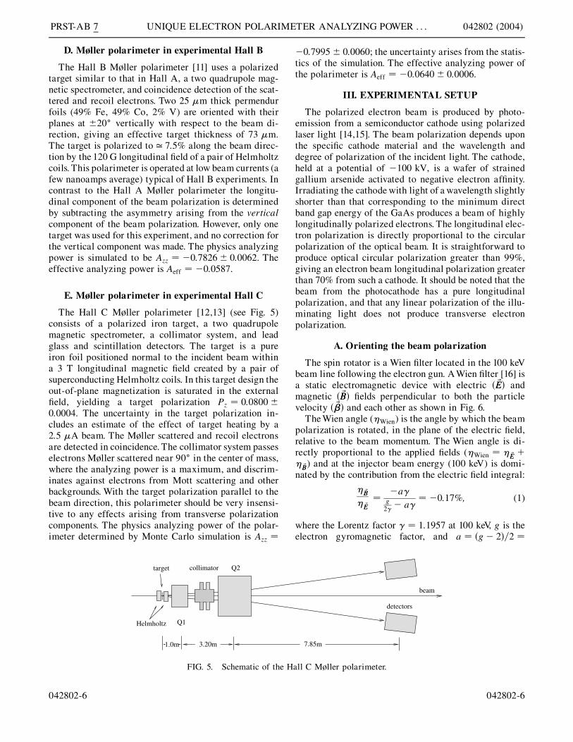
The Hall C Møller polarimeter [12,13] (see Fig. 5)consists of a polarized iron target, a two quadrupolemagnetic spectrometer, a collimator system, and leadglass and scintillation detectors. The target is a pureiron foil positioned normal to the incident beam withina 3 T longitudinal magnetic field created by a pair ofsuperconducting Helmholtz coils. In this target design theout-of-plane magnetization is saturated in the externalfield, yielding a target polarization Pz � 0:0800�0:0004. The uncertainty in the target polarization in-cludes an estimate of the effect of target heating by a2:5 �A beam. The Møller scattered and recoil electronsare detected in coincidence. The collimator system passeselectrons Møller scattered near 90� in the center of mass,where the analyzing power is a maximum, and discrim-inates against electrons from Mott scattering and otherbackgrounds. With the target polarization parallel to thebeam direction, this polarimeter should be very insensi-tive to any effects arising from transverse polarizationcomponents. The physics analyzing power of the polar-imeter determined by Monte Carlo simulation is Azz �
1.0m
Helmholtz
collimator
Q1
Q2
3.20m
target
FIG. 5. Schematic of the H
042802-6
�0:7995� 0:0060; the uncertainty arises from the statis-tics of the simulation. The effective analyzing power ofthe polarimeter is Aeff � �0:0640� 0:0006.
III. EXPERIMENTAL SETUP
The polarized electron beam is produced by photo-emission from a semiconductor cathode using polarizedlaser light [14,15]. The beam polarization depends uponthe specific cathode material and the wavelength anddegree of polarization of the incident light. The cathode,held at a potential of �100 kV, is a wafer of strainedgallium arsenide activated to negative electron affinity.Irradiating the cathode with light of a wavelength slightlyshorter than that corresponding to the minimum directband gap energy of the GaAs produces a beam of highlylongitudinally polarized electrons. The longitudinal elec-tron polarization is directly proportional to the circularpolarization of the optical beam. It is straightforward toproduce optical circular polarization greater than 99%,giving an electron beam longitudinal polarization greaterthan 70% from such a cathode. It should be noted that thebeam from the photocathode has a pure longitudinalpolarization, and that any linear polarization of the illu-minating light does not produce transverse electronpolarization.
A. Orienting the beam polarization
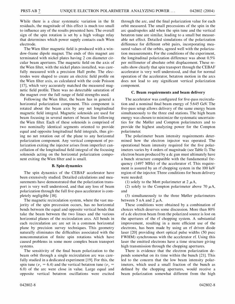
The spin rotator is a Wien filter located in the 100 keVbeam line following the electron gun. A Wien filter [16] isa static electromagnetic device with electric � ~EE andmagnetic � ~BB fields perpendicular to both the particlevelocity � ~�� and each other as shown in Fig. 6.
The Wien angle (�Wien) is the angle by which the beampolarization is rotated, in the plane of the electric field,relative to the beam momentum. The Wien angle is di-rectly proportional to the applied fields (�Wien � � ~EE �� ~BB) and at the injector beam energy (100 keV) is domi-nated by the contribution from the electric field integral:
� ~BB
� ~EE�
�a�g2�� a�
� �0:17%; (1)
where the Lorentz factor � � 1:1957 at 100 keV, g is theelectron gyromagnetic factor, and a � �g� 2=2 �
7.85m
beam
detectors
all C Møller polarimeter.
042802-6

X
Z
P ηWien
MAGNETICFIELD
ELECTRICFIELD
Beam
FIG. 6. Diagram of a Wien filter indicating the rotation of the beam polarization relative to the beam direction (�Wien) in crossedmagnetic and electric fields ( EB � �). In this experiment, the electric field and the spin rotation are in the horizontal plane.
PRST-AB 7 J. M. GRAMES et al. 042802 (2004)
1:159 652 10�3. The utility of the Wien filter is that thepolarization of a beam passing through the device can berotated in the plane of the electric field without changingthe central beam orbit.
The transverse electric field is produced along the mid-plane of the Wien filter by two electrodes which span itslength. The electrode voltages are set by two oppositepolarity 15 kV power supplies controlled by a commondigital to analog converter (DAC), so that the potential onaxis is zero. A magnetic field normal to the electric field isapplied to balance the Lorentz force on the beam axis,
FIG. 7. Wien voltage with second-order polynomial fit (upper paneDAC set point (Sdac).
042802-7
~FF � q� ~EE� ~�� ~BB � 0; (2)
requiring that j EB j � �.The voltage applied across the two electrodes was
calibrated against the common DAC setting, with theresults shown in Fig. 7. The response is modeled by asecond-order polynomial giving the power supply offset,gain, and linearity as a function of the DAC setting
VWien � ��p0 � p1 � Sdac � p2 � S2dac: (3)
l) and fit residuals (lower panel) both shown as a function of the
042802-7
PRST-AB 7 UNIQUE ELECTRON POLARIMETER ANALYZING POWER . . . 042802 (2004)
While there is a clear systematic variation in the fitresiduals, the magnitude of this effect is much too smallto influence any of the results presented here. The overallsign of the spin rotation is set by a high voltage relaythat determines which power supply contacts each Wienelectrode.
The Wien filter magnetic field is produced with a win-dow-frame dipole magnet. The ends of this magnet areterminated with nickel plates having 2 cm diameter cir-cular beam apertures. The magnetic field on the axis ofthe Wien filter, with the nickel plates installed, was care-fully measured with a precision Hall probe. The elec-trodes were shaped to create an electric field profile onthe Wien filter axis, as calculated with the code Poisson[17], which very accurately matched the measured mag-netic field profile. There was no detectable saturation ofthe magnet over the full range of field strengths used.
Following the Wien filter, the beam has in general ahorizontal polarization component. This component isrotated about the beam axis by any net longitudinalmagnetic field integral. Magnetic solenoids are used forbeam focusing in several meters of beam line followingthe Wien filter. Each of these solenoids is comprised oftwo nominally identical segments oriented to provideequal and opposite longitudinal field integrals, thus giv-ing no net rotation out of the plane to any horizontalpolarization component. Any vertical component of po-larization exiting the injector arises from imperfect can-cellation of the longitudinal field integral of the focusingsolenoids acting on the horizontal polarization compo-nent exiting the Wien filter and is small.
B. Spin dynamics
The spin dynamics of the CEBAF accelerator havebeen extensively studied. Detailed calculations and mea-surements have demonstrated that the polarization trans-port is very well understood, and that any loss of beampolarization through the full five-pass accelerator is com-pletely negligible [18].
The magnetic recirculation system, where the vast ma-jority of the spin precession occurs, has no horizontalbends between the equal and opposite vertical bends thattake the beam between the two linacs and the varioushorizontal planes of the recirculation arcs. All bends ineach recirculation arc are set in a common horizontalplane by precision survey techniques. This geometrynaturally eliminates the difficulties associated with thenoncommutation of finite spin rotations which havecaused problems in some more complex beam transportsystems.
The sensitivity of the final beam polarization to thebeam orbit through a single recirculation arc was care-fully studied in a dedicated experiment [19]. For this, thespin tune (�s � 6:4) and the vertical betatron tune (�y �6:0) of the arc were close in value. Large equal andopposite vertical betatron oscillations were excited
042802-8
through the arc, and the final polarization value for eachorbit measured. The small precessions of the spin in thearc quadrupoles add when the spin tune and the verticalbetatron tune are similar, leading to a small but measur-able net effect. Detailed simulations of the polarizationdifference for different orbit pairs, incorporating mea-sured values of the orbits, agreed well with the polariza-tion measurements. For the conditions of the experiment,the longitudinal polarization difference was about 0.5%per millimeter of absolute orbit displacement. These re-sults show clearly that spin transport through the CEBAFaccelerator is very well understood, and that for normaloperation of the accelerator, betatron motion in the arcsdoes not lead to any significant vertical polarizationcomponent.
C. Beam requirements and beam delivery
The accelerator was configured for five-pass recircula-tion and a nominal final beam energy of 5.645 GeV. Thefive-pass setup allows delivery of the same energy beamsimultaneously to the three end stations. The high beamenergy was chosen to minimize the systematic uncertain-ties for the Møller and Compton polarimeters and toprovide the highest analyzing power for the Comptonpolarimeter.
The polarimeter beam intensity requirements deter-mined how the electron injector was operated. Theoperational beam intensity required for the five polar-imeters varies by 4 orders of magnitude (see Table I). Theelectron beam produced by a dc gun must ultimately havea bunch structure compatible with the fundamental fre-quency (1497 MHz) of the accelerator rf. This require-ment is assured by an rf chopping system in the 100 keVregion of the injector. Three conditions for beam deliverywere needed:
(1) solely to the Mott polarimeter at 2 �A,(2) solely to the Compton polarimeter above 70 �A,
and(3) simultaneously to the three Møller polarimeters
between 5 nA and 2 �A.These conditions were obtained by a combination of
choices which deserves some discussion. More than 80%of a dc electron beam from the polarized source is lost onthe apertures of the rf chopping system. A substantialimprovement, resulting in a more efficient use of theelectrons, has been made by using an rf driven diodelaser [20] providing short optical pulse widths (50 psecFWHM) synchronous with the accelerator rf. Using thislaser the emitted electrons have a time structure givinghigh transmission through the chopping apertures.
There is evidence that the electron polarization de-pends somewhat on its time within the bunch [21]. Thisled to the concern that the low beam intensity polar-imeters, which used a small fraction of the bunch asdefined by the chopping apertures, would receive abeam polarization somewhat different from the high
042802-8

PRST-AB 7 J. M. GRAMES et al. 042802 (2004)
beam intensity Compton polarimeter, which used essen-tially all ( > 98%) of the bunch.
To address this concern the photoinjector was operatedin two different modes. In the first of these, a true dcbeam was delivered from the photoemission gun by ap-plying a dc current to the laser. This beam was choppedand bunched in the normal manner, with beam intensityadjustment provided by the chopping apertures. With a dcbeam from the polarized gun, the polarization is inde-pendent of the time within the bunch. Both Mott andMøller measurements were made with this beam.
The second operating mode was used for the Comptonmeasurements, using the rf driven laser and fully openchopping apertures to reach the higher beam intensity.With the rf driven laser illuminating the cathode, and thefully open chopping apertures, the chopping systempasses essentially all of the beam, so there is no issue ofbeam polarization dependence on time within the bunch.The same laser and optical polarization elements wereused for both the dc and the rf cases. Only the electricaldrive to the laser was changed between the dc and therf cases.
Beam was delivered to the Mott polarimeter alone,using magnetic deflection in the injector, simultaneouslyto the three Møller polarimeters using rf separation of thehigh energy beam [22] and to the Compton polarimeteralone by magnetically deflecting the high energy beam.
IV. POLARIMETER MEASUREMENTS ANDEXPERIMENTAL RESULTS
Polarimeter data were collected at 12 different Wienangles spanning j�Wienj< 110�. The polarimeter data
TABLE II. Summary of polarization measurequoted for each polarimeter. All measurements wthe Compton measurements which all used thestatistical only.
�Wien Mott Compton A M(deg) (%) (%)
�10:54 �71:05� 0:90 �7�10:54 �71:22� 0:85
57.07 �58:90� 0:30 �3108.79 �69:00� 0:30 393.27 �72:80� 0:30 14:41� 1:3077.75 �70:60� 0:30 �10:82� 0:61 �177.75 �10:81� 0:7436.38 �510.54 �10:70� 0:40 �7
�10:54 13:90� 0:40 �71:52� 1:87 �7�10:54 �78:95� 1:73�41:55 48:00� 0:40 �58:52� 0:66�41:55 �56:71� 0:79�60:16 62:90� 0:40 �4�84:99 72:20� 0:20 �1�108:79 68:00� 0:50 2
042802-9
were analyzed by each respective polarimeter group.The measured components of the beam polarization re-ported by each group are given in Table II.
We report the measured longitudinal polarization forthe Møller and Compton polarimeters, and the measuredtransverse polarization in the horizontal plane for theMott polarimeter. The measured polarization values areproportional to the product of the longitudinal beampolarization from the photocathode and the cosine ofthe Wien angle plus the total precession angle.
The measured polarizations from each polarimeter aremodeled as
Pmeas � Pi cos��i � VWien ��i ��g; (4)
where Pi, �i, and �i are the fit parameters. Pi and �i arethe magnitude of the measured beam polarization and thetotal spin precession between the Wien filter and theparticular polarimeter. Although the fit function is peri-odic, the total beam precession modulo 2 is known tomuch better than one full revolution. Accordingly, theseed value of �i for the fitting routine is set to anappropriate value for each experimental hall. The value�g � a�! � �0:01� is a correction for a single dipolemagnet (! � �15�) located between the electron sourceand the Wien filter. The coefficient �i is the constantrelating the spin rotation of the Wien filter to the Wienfilter high voltage.
The probable values of the fit parameters and theiruncertainties are determined from the polarimeterdata of Table II using a nonlinear least squares fittingroutine [23,24]. Because we are investigating the relativeanalyzing power of the polarimeters without presuming
ments, using the effective analyzing powerere made using the dc laser mode except forrf laser mode. The uncertainties below are
øller A Møller B Møller C(%) (%) (%)
4:65� 0:17
6:42� 0:18 �32:65� 1:02 73:62� 0:172:09� 0:14 �70:64� 1:02 43:56� 0:269:45� 0:10 �64:31� 1:61 59:80� 0:272:44� 0:16 �51:97� 0:91 69:50� 0:18
9:77� 0:16 �8:65� 0:88 67:27� 0:183:02� 0:14 24:05� 0:89 49:37� 0:204:73� 0:14 43:40� 0:99 28:65� 0:26
5:38� 0:13 69:11� 1:02 �30:66� 0:262:39� 0:17 61:95� 1:05 �58:06� 0:224:02� 0:14 45:19� 0:99 �72:59� 0:23
042802-9

TABLE III. �i determined by Eq. (4) for each polarimeterand the weighted average, �.
Polarimeter �i ( deg=kV)
Mott 5:553� 0:038Møller A 5:666� 0:043Møller B 5:704� 0:047Møller C 5:615� 0:052Compton 5:779� 0:169� (weighted average) 5:630� 0:022
PRST-AB 7 UNIQUE ELECTRON POLARIMETER ANALYZING POWER . . . 042802 (2004)
systematic uncertainties, care must be taken to estimatethe probable values of the fit parameters and their un-certainties. In doing so we cannot use only the statisticalerrors reported in Table II because this would underesti-mate the true variance in a polarimeter data set. Theapproach taken [24,25] is to assume that we do notknow the individual measurement errors and to assignto each measurement in a polarimeter data set an equalunit weight error. Consequently, the standard error ofestimate for the fit parameters from each data set is givenby the root mean square statistical errors of estimate ofthe covariance matrix, weighted by the reduced chisquare of the fit
���������������������������"2=�N �M
p. Here "2 is the least
squares estimate evaluated at the most probable fit pa-rameters, N is the number of measurements in a data set,and M is the number of fit parameters. This approachdepends upon the following assumptions:
(i) we are using the correct model to describe the data[see Eq. (4)],
(ii) the systematic errors do not change within a dataset, and
(iii) the total measurement error of each data pointwithin a data set is approximately equal, requiring thateach measurement has a very similar statistical precision.
While the first and third assumptions are valid, it isimportant to note that the systematic uncertainty maydepend on the degree of horizontal polarization for somepolarimeters, so the second assumption may not be met inall cases. We have not attempted to analyze how thismight affect our results.
To compare the polarimeters one must additionallyconstrain the parameter �i to be equal for all polarimeter
TABLE IV. Polarization and phase results foitalicized text show the values obtained usingtotal standard error in the fit parameters using t
Polarization (%)Polarimeter � �i
Mott 72:10� 0:28 72.19�0.24Møller A 76:76� 1:04 76.79�1.06Møller B 69:84� 0:64 69.81�0.59Møller C 73:30� 0:62 73.29�0.66Compton 73:33� 1:42 74.25�1.84
042802-10
data measured at identical Wien angle settings.Consequently, the analysis was segmented into twostages. In the first stage all three fit parameters are esti-mated and the weighted average (�) of the set of �i (seeTable III) is computed. In the second stage each data setwas fit again using Eq. (4) with �i replaced by theweighted average value �. The first stage analysis of thedata gives a �i that varies by 4.0% between the extremesof the polarimeter data sets. This variation is attributed toan unmeasured systematic effect and is included in theuncertainty of the fit. Although unexpected, this variationhas little impact on the final determination of the beampolarization and spin phase, as demonstrated below.
The final fit results and residuals are shown in Fig. 8. InTable IV we compare the results obtained for Pi and �ifor each polarimeter using both the individual �i for thatpolarimeter and using �. In all cases the differences in thefit results using either �i or � are small compared to thestandard error from the least squares fitting routine.
It is important to understand that the systematic un-certainties associated with each polarimeter are not in-cluded in the polarization results given in Table IV andFig. 8. A motivation for this experiment is to find evi-dence of undetected systematic effects or other problemswith the quoted effective analyzing powers of the variouspolarimeters by comparing the polarization determinedby each polarimeter when all measure the same polarizedbeam. When systematic effects are included, the uncer-tainties on the polarization values reported in Table IVand Fig. 8 will be larger.
A comparison of the beam polarizations determinedfrom each polarimeter data set is made in Fig. 9 byplotting the ratio of the measured polarization values(Pi) with respect to a reference. In this case, the Mottpolarimeter was chosen as the reference because it had thesmallest relative uncertainty in the fit parameter Pi. Theratio of the effective analyzing power of any polarimeterrelative to the Mott polarimeter is the inverse of the ratioshown in Fig. 9.
As noted earlier, when the longitudinal polarizationcomponent is small, the horizontal component is large.Some polarimeters may have systematic effects that de-pend on the horizontal component. An indication of the
r polarimeter data using � � 5:630�=kV;the individual �i. The uncertainties are thehe least squares fitting routine.
Phase (deg)� �i
88:88� 0:32 88.82�0.2710 983:84� 0:63 10 983.75�0.6410 500:48� 0:56 10 500.30�0.5310 023:39� 0:61 10 023.40�0:6510 984:82� 1:33 10 983.07�2.36
042802-10

FIG. 8. (Color) Measured polarizations and fits (upper plot) using � and all data. Fit residuals (lower plot), with only statisticaluncertainties from the fits shown. In general, the uncertainties from the fits are smaller than the symbol sizes used in plotting thedata. Note: the lower plot legend applies to the upper plot.
PRST-AB 7 J. M. GRAMES et al. 042802 (2004)
importance of this effect may be had by fitting Eq. (4) todata sets containing only large longitudinal polarizationvalues. Figure 10 and TableVshow the results of fits wherethe data fitted have been restricted to be within 25% of
FIG. 9. (Color) The relative analyzing powers for the five Jeffersonpolarimeter for comparison.
042802-11
the maximum polarization value. Such fits do not give asgood values for �i, but still give good values for Pi. Theratio of these polarization values to the Mott polarizationvalue is given in Fig. 11. These results indicate that the
Laboratory electron beam polarimeters, normalized to the Mott
042802-11

FIG. 10. (Color) Polarimeter data and fit (upper plot) using � and data set limited to be within 25% of the maximum polarization.Fit residuals (lower plot) are shown using only statistical uncertainties from polarimeter data. Note: the lower plot legend applies tothe upper plot.
PRST-AB 7 UNIQUE ELECTRON POLARIMETER ANALYZING POWER . . . 042802 (2004)
horizontal component of polarization may be an impor-tant source of systematic effects for the Hall A Møllerpolarimeter.
V. BEAM ENERGY MEASUREMENTS
The beam energy is usually measured by either highprecision magnetic spectrometer or elastic electron-
TABLE V. Polarization and phase results for pothe maximum polarization measured; italicizedfor comparison. The uncertainties are the total sleast squares fitting routine. Results presented in
Polarization (%)Polarimeter 25% restriction All data
Mott 72:27� 0:23 72.10�0.2Møller A 75:40� 0:33 76.76�1.0Møller B 70:01� 1:80 69.84�0.6Møller C 73:37� 0:42 73.30�0.6Compton 73:85� 2:15 73.33�1.4
042802-12
proton scattering methods. An additional benefit of thepolarimeter intercomparison is that the spin precessiondata can be used for a precision determination of the beamenergy, due to the linear relationship between the spinprecession and the beam energy. One of two independentspin-based approaches, described below, is shown to becapable of yielding an extremely precise absolute mea-surement �<10�4 of the beam energy.
larimeter data restricted to be within 25% oftext show results using all data (see Table IV)tandard error in the fit parameters using the
this table use � � 5:630�=kV.
Phase (deg)25% restriction All data
8 88:59� 0:50 88.88�0.324 10 981:60� 0:68 10 983.84�0.634 10 501:07� 4:54 10 500.48�0.562 10 021:70� 0:74 10 023.39�0.612 10 982:86� 4:10 10 984.82�1.33
042802-12

FIG. 11. (Color) The relative analyzing powers for the five Jefferson Laboratory electron beam polarimeters, normalized to theMott polarimeter for comparison. The solid symbol markers represent the results for the data set limited to be within 25% of themaximum measured polarization. The open symbol markers are the results shown in Fig. 9.
TABLE VI. Transformations to practical acceleratorparameters.
Quantity Transformation
Final beam energy E0 � n�E1 � E2 ! ELinac imbalance E1 � E2 ! E12
Total bend angle n!1 � �n� 1!2 � !h ! !tLinac skewness !1 � !2 ! !12
PRST-AB 7 J. M. GRAMES et al. 042802 (2004)
For comparison, the beam energy was measured usingthe magnetic spectrometer method [26]. Two pairs ofbeam profile monitors measured the beam direction be-fore and after a string of eight well-measured dipolemagnets leading into Hall A to determine the resultingbeam deflection. This measurement gave a five-pass beamenergy of 5646:5� 3:0 MeV.
A. Method No. 1: Beam energy measured byspin precession between the injector and the
experimental halls
The electron beam gains an initial energy in the in-jector. After injection into the main accelerator the elec-tron beam successively gains energy in each linac duringeach recirculation pass (see Fig. 1). The dipole magnets inthe recirculation and experimental hall transport arcsprecess the beam polarization. The total spin precessionbetween the injector and any experimental hall, as mea-sured by the Mott polarimeter and the correspondingexperimental hall polarimeter, can be exactly calculated.For n recirculations through the accelerator (n � 5 forthis experiment) the total precession, �n, can be summedand written, after some algebraic manipulation, as
�n �
�g� 2
2me
�f�n!1 � �n� 1!2�E0
�n2��n� 1!1 � �n� 1!2�E1
�n�n� 1
2�!1 � !2E2
� �E0 � n�E1 � E2!h�g; (5)
where E0, E1, and E2 are the energy gains of the injector,north linac and south linac, !1 and !2 are the bend anglesof the east and west recirculation arcs, and !h is the bendangle of the respective experimental hall transport arc(h 2 fA;B;Cg). Note that Eq. (5) assumes that the energygain on each pass through each linac is the same. In
042802-13
practice, this is assured by measuring and correctingthe total path length of each recirculation pass. Thesystem developed to do this allows the path length oneach pass to be set with a 2( precision of better than 0.25rf degree, leading to negligible differences in the energygain on each pass [27]. It is useful to transform Eq. (5) toparameters more practical (see Table VI) for evaluatingthe beam energy.
After manipulation, the final beam energy is written interms of these accelerator parameters and the total spinprecession determined from the polarimeter measure-ments as
E �
4me�ng�2 � E0�!t � !h �
nE12�!t�!h��n�1!12��2n�1
!t � !h: (6)
The main advantage of this method is that at the high-est CEBAF energies one can take advantage of the verylarge total precession (� > 10 000�) to reach an absolutemeasurement of the beam energy to better than 10�4. Todo so requires precise knowledge of the accelerator pa-rameters in Eq. (6). The sensitivity of the beam energy tothese parameters is given in Table VII and is described inmore detail below.
Uncertainty in the injector beam energy (E0) is asignificant contribution to the total uncertainty becausethis fraction of the beam energy is precessed by each
042802-13

TABLE VII. The derivative of Eq. (6) with respect to each of the dependent parameters isshown alongside the corresponding the numerical value calculated for Hall B. The numericalvalues for Halls A and C are within 5% of the values for Hall B.
Derivative Numerical value
�@E=@�n � �4me=�g� 2�=�!t � !h 0:544 MeV= deg�@E=@E0 � ��!t � !h=�!t � !h �1:00 MeV=MeV
�@E=@!12 � ��n�n� 1E12=�2n� 1�=�!t � !h �0:00713 MeV= deg�@E=@E12 � �nf�!t � !h � �n� 1!12�=��2n� 1�!t � !h�g �0:556 MeV=MeV
�@E=@!t � ��E� E0 � nE12=�2n� 1�=�!t � !h �3:527 MeV= deg�@E=@!h � ��E� E0 � nE12=�2n� 1�=�!t � !h �3:449 MeV= deg
TABLE VIII. The gyrotheodolite survey measurements areshown along with the resulting calculated parameters neededfor the spin precession results. The angle of the beam line toHall B was not surveyed with the gyrotheodolite and isincluded as an assumed value.
Quantity Acquired Angle (deg)
!h�A Measured 37:4913� 0:0020!h�B Assumed 0:0000� 0:0100!h�C Measured �37:4774� 0:0057!1 Measured 180:0000� 0:0020!2 Measured 180:0000� 0:0020!12 Calculated 0:0000� 0:0020!t�A Calculated 1657:4913� 0:0024!t�B Calculated 1620:0000� 0:0101!t�C Calculated 1582:5226� 0:0058
PRST-AB 7 UNIQUE ELECTRON POLARIMETER ANALYZING POWER . . . 042802 (2004)
dipole magnet of the accelerator. The injector beam mo-mentum was measured immediately prior to the experi-ment using a recent high precision calibration of theinjector spectrometer [28]. This gives a value for theinjector beam energy of E0 � 62:89� 0:06 MeV.
The precision with which the bend angles of the recir-culation arcs �!1; !2 and hall transport arcs �!h is knownalso impacts the energy measurement. These angles havebeen determined by high precision survey measurementsof beam line elements in the linacs and at the beginningand end of the transport beam lines into experimentalHalls A and C. The survey measurements are made withrespect to the accelerator site reference grid, which in turnis established within a network of survey monumentsspanning the accelerator site.
At the time of the measurements reported here, gyro-theodolite measurements [29] were made at a number oflocations throughout the accelerator site to confirm theoverall shape and stability of the accelerator site referencegrid. A gyrotheodolite is an instrument that measures,with very high precision (ca. 3 arc sec), the horizontaldirection of a line with respect to true north— the Earth’saxis of rotation. The gyrotheodolite was used to transfer acommon high precision directional reference to locationsthroughout the accelerator tunnel complex. One can thencompare the azimuths as determined from the gyrotheo-dolite measurements to azimuths calculated from preci-sion survey measurements. There are three sources ofmeasurement uncertainty in determining these angles:(a) the 3 arc sec uncertainty of the gyrotheodolite; (b)an azimuthal uncertainty resulting from the transverseposition measurement uncertainty of 0.25 mm and theseparation of the beam line elements; and (c) an azimu-thal uncertainty resulting from the transverse componentof the fiducialization uncertainty of 0.05 mm and theseparation of the beam line elements. Using normal errorpropagation, these differences in azimuth were less than1.5 arc sec in the linacs, approximately 10 arc sec in thebeam switchyard, less than 5 arc sec in the Hall A trans-port line, and less than 10 arc sec in the Hall C transportline. Overall, the gyrotheodolite measurements verify theaccelerator site reference grid at the level of the 3 arc secgyrotheodolite measurement uncertainty and justify the
042802-14
use of precision survey measurements to determine theangles necessary for the energy determination. The an-gles used are given in Table VIII.
Finally, the polarization precession depends on thelinac energy imbalance, E12, which is the difference inthe energy gain between the north and the south linacs.Consider the case in which the energy gained in one fullrecirculation pass is fixed. The west recirculation arcsfollow both linacs, so the precession in these arcs doesnot depend on the equality of the linac energy gains.However, the east recirculation arcs follow only the northlinac, and thus the precession in these arcs depends onE12. In particular, precession in the east arcs is greaterwhen E12 > 0.E12 was not measured at the time of the precession
measurements reported here. Instead, this measurementwas made soon afterward, when the energy gain in eachlinac had been increased a nominal 7%. To measure E12 asingle pass beam was sent to Hall A, and its energy wasdetermined by the standard method of measuring thetotal deflection through the eight Hall A transport di-poles. The beam energy was measured with both linacspowered, and with only the north linac powered and thebeam simply drifted through the unpowered south linac.
042802-14

TABLE IX. Summary of measurements to determine thelinac energy imbalance.
Quantity Acquired Beam energy (MeV)
Injector Measured 67:89� 0:07North linac only Measured 671:14� 0:28North and south linac Measured 1270:26� 0:52E1 Calculated 603:25� 0:29E2 Calculated 599:12� 0:59
PRST-AB 7 J. M. GRAMES et al. 042802 (2004)
The results are reported in Table IX. These measurementsgave a value of 4:13� 0:66 MeV for E12 at this energy.
The value of E12 at the energy used for the precessionmeasurements was determined by scaling to the lowerenergy, using accelerator parameters measured at eachenergy. Two different methods were used to do this scal-ing. In the first of these, the sum of the acceleratinggradients of the 160 cavities in each linac was comparedat the two beam energies. In the second, detailed mea-surements of the beam orbit through the first and secondrecirculation arcs, coupled with measurements of thedipole bus current in these arcs, were used. These twoscaling methods gave values for E12 of 4:75� 0:76 MeVand 5:69� 0:95 MeV, respectively. The weighted meanof these two values is 5:17� 0:59 MeV. For the analysispresented here, we use the value E12 � 5:2� 1:0 MeV.The enlarged uncertainty in the value of E12 is chosen toaccount for any undetected systematic effects associatedwith determining E12 at a different time and with differ-ent linac energy gains.
With the above value for E12, we can determine fourvalues for the final beam energy from the measurementsof the total precession to the four hall polarimeters. Thesevalues are presented in Table X. The total five-pass pre-
TABLE XI. Summary of energy measuremenimeters by the relative spin precession method.
Polarimeters $� (deg)
Møller A-Møller B 483:36� 0:84 37:4Møller A-Møller C 960:45� 0:88 74:9Compton A-Møller B 484:34� 1:44 37:4Compton A-Møller C 961:43� 1:46 74:9Møller B-Møller C 477:09� 0:83 37:4
TABLE X. Final beam energies measured by total precessionevaluated at E12 � 5:2� 1:0 MeV.
Polarimeters � (deg) E (MeV)
Mott-Compton 10 985:94� 1:37 5649:21� 0:89Mott-Møller A 10 984:96� 0:71 5648:70� 0:65Mott-Møller B 10 501:60� 0:64 5647:20� 0:66Mott-Møller C 10 024:51� 0:69 5649:03� 0:71
042802-15
cession for each polarimeter is that listed in Table IV,corrected by the polarization orientation as measured inthe injector by the Mott polarimeter (1:12� � 0:32�).
B. Method No. 2: Beam energy measured byrelative spin precession differences between
experimental halls
The alternative to comparing the total precession be-tween the injector and an experimental hall polarimeteris simply to use the precession difference between eachexperimental hall. The advantage is that prior to extrac-tion, the beam to each hall undergoes identical precession.In this way the injector energy, linac imbalance, andrecirculation arc bend angles are eliminated from theequation and the precession between any two experimen-tal hall polarimeters is given simply by
$� �g� 2
2
E
mec2� $%; (7)
where $� and $% are the measured differences in theprecession and bend angle between two respective hallpolarimeters. E is the final beam energy common to both.In this case, the uncertainty in the bend angle is the maincontribution to the energy uncertainty. The disadvantageof this method is that the precession difference betweendifferent experimental hall polarimeters is much smallerthan the precession through the full five-pass accelerator.Thus, even at the maximum CEBAF energy, the statisti-cal precision of this energy measurement is of order 10�3.The beam energies obtained from the precession differ-ences between the four experimental hall polarimetersare given in Table XI.
C. Final energy determination
Both the injector to experimental hall and experimen-tal hall to experimental hall spin-based energy measure-ment methods indicate discrepancies associated with theHall B polarimeter. The energy as determined by theprecession from the injector to the Hall B polarimeteris somewhat in disagreement ( > 2() with the energydetermined with the three other polarimeters, all ofwhich are themselves in good agreement. The energiesdetermined from the precession difference between theHall A and Hall C polarimeters are consistent with one
t results comparing only end-station polar-
$% (deg) E (MeV) (EE (%)
913� 0:0102 5681:10� 10:03 0.176687� 0:0060 5645:30� 5:17 0.092913� 0:0102 5692:62� 17:03 0.299687� 0:0060 5651:07� 8:61 0.152774� 0:0115 5609:49� 9:89 0.176
042802-15

PRST-AB 7 UNIQUE ELECTRON POLARIMETER ANALYZING POWER . . . 042802 (2004)
another and consistent with the much more precise valuesdetermined by the total precession method. However,there are large and statistically untenable discrepanciesin the energies determined by using the precession dif-ferences between the Hall B polarimeter and the Hall Aand C polarimeters. When comparing either the Hall A orHall C polarimeter to the Hall B polarimeter these dis-crepancies, about 37 MeV (see Table XI), clearly indicatethat the difference is associated with whether the com-parison polarimeter is located in Hall A (higher energy)or Hall C (lower energy).
Inspection of Eq. (7) shows that the discrepanciesassociated with the Hall B polarimeter can be resolvedby either increasing the total precession from the injectorto the Hall B polarimeter, �, by 3:4� or an angular shiftof the Hall B beam line, !h�B, by 0:26� further from HallA and closer to Hall C.
Inserting these two possibilities into Eq. (6) for theenergy determined from the total spin precession methodyields a beam energy of 5649:05� 0:66 for the modifiedprecession or 5648:10� 0:66 for the modified beam line.In either case, these new values agree better with theenergy as determined by the total precession to theHalls A and C polarimeters.
It is not possible to determine the source of the dis-crepancy associated with the Hall B polarimeter energydetermination from our measurements. The required shiftin precession of about 3:4� is very large compared to thestandard deviation of the fit value for the Hall B totalprecession (0:64�), making a precession error this largeunlikely. The angle of the beam line into Hall B was notdetermined as part of the precision gyrotheodolite sur-vey, leaving open the possibility that there is a smallangular misalignment of the polarimeter beam line.Further measurements are required to resolve the presentdiscrepancy.
At this point, we choose to ignore all energy measure-ments involving the Hall B polarimeter. We can deter-mine a best value for the full five-pass accelerator energyfrom the three independent measurements of the totalprecession from the injector to the two Hall A and oneHall C polarimeters. The statistically weighted energy asdetermined from these three measurements is 5648:94�0:42 MeV. This value is within less than 1 standard de-viation of the value of 5646:5� 3:0 MeV as determinedby the magnetic spectrometer method.
VI. CONCLUSIONS
A careful comparison of the relative analyzing powersof the five Jefferson Laboratory electron polarimeters,based on Mott, Møller, and Compton scattering, hasbeen performed. This was accomplished by using aWien filter spin rotator located in the low energy regionof the injector to orient the electron spin between �110�
relative to the beam direction in the horizontal plane.
042802-16
Asymmetry measurements as a function of this spinorientation were conducted with each polarimeter. Sinceeach polarimeter measures a beam with the samemagnitude of polarization, a determination of the relativeanalyzing power of the various polarimeters is straight-forward. Furthermore, a measurement of the spin orien-tation, as set by the Wien filter, that produces maximumlongitudinal polarization at each polarimeter leads to avery high precision energy measurement. At the accelera-tor energies employed in this experiment, measurementof the total precession from the injector to a single polar-imeter leads to a determination of the beam energy with aprecision of about 10�4.
We make the following observations with respect toour results.
(i) Polarimeters: It is clear from these results that thefive Jefferson Lab polarimeters do not all agree on themeasured beam polarization at the level of a few percent.The effective analyzing power of each of these polar-imeters is a simulated number. Polarimeter comparisonsof this type help to reveal undetected systematic effectsand other sources of error in the simulated values of theeffective analyzing powers. A thorough understanding ofpolarimeter systematic effects will be necessary toachieve absolute electron polarimetery at the 1% level,as is required for some proposed parity violation mea-surements. While precision comparisons of polarimetereffective analyzing powers can never guarantee that theeffective analyzing powers used are correct, agreementamong the values of the beam polarization as measuredby very different polarimeters provides strong circum-stantial evidence that no large systematic effects havebeen overlooked. In general, our results indicate howdifficult it will be to establish a convincing case that apolarimeter is capable of 1% absolute electron polariza-tion measurements.
The polarimeter comparison presented here is interest-ing in that we have reported measurements of the longi-tudinal polarization component only. In all cases, thesemeasurements were made with a highly polarized beam.Thus, when the measured longitudinal component issmall there is necessarily a large transverse componentin the horizontal plane for these measurements. The pres-ence of a large transverse spin component may result insystematic effects in the effective longitudinal analyzingpower of a particular polarimeter. Our measurementsindicate that large transverse spin components may bean important source of systematic effects for conven-tional Møller polarimeters.
Finally, it is worth noting that the beam polarizationsdetermined by the injector Mott polarimeter, the Hall ACompton polarimeter, and the Hall C Møller polarimeterare in reasonable statistical agreement with a single value.Note that the errors on the values given in Table IV arefrom the fit only and do not include either the measure-ment statistics or the systematic uncertainty estimated for
042802-16

PRST-AB 7 J. M. GRAMES et al. 042802 (2004)
each polarimeter. The actual uncertainties in the mea-sured polarization values are larger than those shown inTable IV. This result implies that the analyzing powers ofthese three very different polarimeters are reasonablywell understood.
(ii) Wien filter: The value of the Wien angle coefficient�, as determined from fits of the longitudinal polarizationmeasured with each polarimeter as a function of theWienangle, depends on the particular polarimeter used. Whilethis effect is not understood, the resulting uncertainty inthe measured analyzing power and precession angle dueto the uncertainty in the value of � is small. Two data sets,taken with the injector Mott polarimeter about one monthapart, gave fit values for � differing by about 1%.Precision measurement of the gap high voltage and themagnet current associated with each measurement, aswell as the magnet hysteresis history, is clearly war-ranted. Operationally, the beam orbit through the Wienfilter may be slightly different with different Wien filtersettings, particularly as the Wien angle becomes large.While this systematic effect does not affect the conclu-sions from the measurements reported here, it should bebetter understood for future polarimeter comparisonmeasurements.
(iii) Energy measurements: The total precession energymeasurement using only the Hall A and Hall C polar-imeters yields a statistically weighted mean, from threeindependent measurements, of 5648:94� 0:42 MeV, or aprecision of 0:74 10�4. The value is well within 1 stan-dard deviation of the magnetic arc spectrometer measure-ment of 5646:5� 3:0 MeV. The systematic uncertaintiesof the magnetic spectrometer measurement are very dif-ferent than the systematic uncertainties of the total pre-cession measurements. The statistically weighted mean ofthese two total energy measurements is 5648:89�0:42 MeV. A major source of uncertainty in the presenttotal precession measurements is the linac energy imbal-ance. The value used in the above measurements includesan enlarged uncertainty to account for the fact that theenergy imbalance was not measured at the same time, orat the exact energy, of the spin-based energy measure-ments. This source of uncertainty could be greatly re-duced in a future spin-based energy measurement. Thereis clear evidence of problems with the energy measure-ments based on the Hall B polarimeter, and some evi-dence of a misalignment of the beam to the Hall Bpolarimeter.
Jefferson Lab is developing high precision electronpolarimetry to meet the needs of future experiments. Acomparison of the beam polarization measured by differ-ent polarimeters observing the same beam is an impor-tant way to gain confidence that the effective analyzingpowers of these polarimeters have been correctly deter-mined. The results presented here clearly demonstratethat measurements of the total precession through theCEBAF accelerator can be used to determine the absolute
042802-17
value of the accelerator energy with exceptional precision.While spin-based energy measurements are too cumber-some for routine use, a program of such measurementscould provide useful high precision cross calibrations ofmore easily applied energy measurement techniques.
ACKNOWLEDGMENTS
This work is the result of contributions by many scien-tists dedicated to producing and measuring the polarizedelectron beam at Jefferson Laboratory. C. Curtis and thealignment group conducted the high precision gyrotheo-dolite measurements necessary to attain the spin-basedenergy measurement results. This work was supported bythe U.S. DOE Contract No. DE-AC05-84-ER40150.
[1] L. G. Levchuk, Nucl. Instrum. Methods Phys. Res., Sect.A 345, 496 (1994).
[2] M. Swartz et al., Nucl. Instrum. Methods Phys. Res.,Sect. A 363, 526 (1995).
[3] C.W. Leemann, D. R. Douglas, and G. A. Krafft, Annu.Rev. Nucl. Part. Sci. 51, 413 (2001).
[4] J. S. Price et al., in Proceedings of the 12th InternationalSymposium on High-Energy Spin Physics (SPIN 96),Amsterdam, Netherlands, 1996 (World Scientific,Singapore, 1996), pp. 727–729.
[5] J. S. Price et al., in Proceedings of the 7th InternationalWorkshop on Polarized Gas Targets and PolarizedBeams, Urbana, IL, 1997 (AIP, Woodbury, NY, 1997),pp. 446– 450.
[6] M. Steigerwald, in Proceedings of the InternationalWorkshop on Polarized Sources and Targets, Erlangen,Germany, 1999 (University of Erlangen–Nurnberg,Erlangen, Germany, 1999), pp. 258–261.
[7] N. Falletto et al., Nucl. Instrum. Methods Phys. Res.,Sect. A 459, 412 (2001).
[8] M. Baylac et al., Phys. Lett. B 539, 8 (2002).[9] HAPPEX, K. A. Aniol et al., Phys. Lett. B 509, 211
(2001).[10] A.V. Glamazdin, et al., Fizika B 8, 91 1999.[11] R. Nasseripour, B. Raue, L. Kramer, and F. Fortier, Bull.
Am. Phys. Soc. 45, 91 (2000).[12] M. Hauger et al., Nucl. Instrum. Methods Phys. Res.,
Sect. A 462, 382 (2001).[13] L. J. deBever, M. Loppacher, J. Zhao, W. A. Tobias, and
B. Zihlmann, in Proceedings of the 12th InternationalSymposium on High-Energy Spin Physics (SPIN 96),Amsterdam, Netherlands, 1996 (Ref. [4]), pp. 768–770.
[14] C. K. Sinclair, in Proceedings of the 1999 IEEE ParticleAccelerator Conference (PAC 99), New York (IEEE,Piscataway, NJ, 1999), pp. 65–69.
[15] M. Poelker et al., in Proceedings of the 14thInternational Spin Physics Symposium (SPIN 2000),Osaka, Japan, 2000 (AIP, Melville, NY, 2000),pp. 943–948.
[16] M. Salomaa and H. Enge, Nucl. Instrum. Methods 145,279 (1977).
042802-17

PRST-AB 7 UNIQUE ELECTRON POLARIMETER ANALYZING POWER . . . 042802 (2004)
[17] K. Halbach, Lawrence Livermore National LaboratoryTechnical Report No. UCRL-17436, 1967.
[18] J. M. Grames, in Proceedings of the InternationalWorkshop on Polarized Sources and Targets, Erlangen,Germany, 1999 (Ref. [6]), pp. 266–269.
[19] J. M. Grames, Ph.D. thesis, University of Illinoisat Urbana–Champaign, 2000, ftp://ftp.jlab.org/pub/grames/thesis.pdf
[20] M. Poelker, Appl. Phys. Lett. 67, 2762 (1995).[21] J. Schuler et al., in Proceedings of the Low Energy
Polarized Electron Workshop (LE98), St. Petersburg,Russia, 1998 (SPES Lab Publishing, St. Petersburg,Russia, 1998).
[22] A. Krycuk, J. Fugitt, A. Johnson, R. Kazimi, andL. Turlington, in Proceedings of the 1993 IEEEParticle Accelerator Conference (PAC 93), Washington,DC (IEEE, Piscataway, NJ, 1993), pp. 939–940.
[23] J. Chuma, Physica Reference Manual v1.3, Vancouver,Canada, triumf computing document tri-cd-93-01
042802-18
ed. 1998, http://www.triumf.info:8081/physica/html/homepage.html
[24] W. Press, S. Teukolsky, W. Vetterling, and B. Flannery,Numerical Recipes in Fortran 77 (Cambridge UniversityPress, New York, 1992), 2nd ed.
[25] P. Bevington, Data Reduction and Error Analysis for thePhysical Sciences (McGraw-Hill, New York, 1969).
[26] J. Berthot and P. Vernin, Nucl. Phys. News 9N4, 12(1999).
[27] D. Hardy, J. Tang, L. R. M. Tiefenback, M. Crofford,and G. A. Krafft, in Proceedings of the 1997 IEEEParticle Accelerator Conference (PAC 97), Vancouver,B.C., Canada (IEEE, Piscataway, NJ, 1997), pp. 2265–2267.
[28] R. Kazimi (private communication).[29] C. Curtis, Jefferson Laboratory Technical Report, 2000,
survey and alignment data transmittals No. L625,No. L634, and No. L643.
042802-18


![[O3] Polarimeter](https://img.dokumen.tips/doc/110x75/5571f2ce49795947648d1635/o3-polarimeter.jpg)