Embed Size (px)
Citation preview

Unified testing framework for GUI tools of variable speed drives
Riku Taivalantti
School of Electrical Engineering
Thesis submitted for examination for the degree of Master of
Science in Technology.
Espoo 30.5.2016
Thesis supervisor:
Professor Ville Kyrki
Thesis advisor
M.Sc. Zhongliang Hu

AALTO UNIVERSITY ABSTRACT OF THE
SCHOOL OF ELECTRICAL ENGINEERING MASTER’S THESIS
Author: Riku Taivalantti
Title: Unified testing framework for GUI tools of variable speed drives
Date: 30.5.2016 Language: English Number of pages: 6+70
Department of Electrical Engineering and Automation
Professorship: Automation technology
Supervisor: Professor Ville Kyrki
Advisor: M.Sc. Zhongliang Hu
Testing is an important way to ensure the quality of embedded systems. To establish
known testing environments and to obtain cost savings through automation,
automated testing frameworks are built around them.
This thesis presents a design of an automated testing framework that unifies
automated testing frameworks of three different graphical user interface tools of
variable speed drives. The new framework is named Unified testing framework and it
allows testing that the three user interface tools work both together and with the
variable speed drives. The thesis has a focus on embedded devices because variable
speed drives and one of the user interface tools is an embedded device. The other two
user interface tools are PC software and smartphone software.
This thesis is structured to four parts. First a literature survey on theory of testing
frameworks is conducted. Then the gained knowledge is applied into analysing the
three existing testing frameworks. After this analysis the design of the Unified testing
framework is presented. The validity of the design is proven using a prototype. The
validation is done based on its coverage, maintainability and performance.
Keywords: Testing framework, Automation, Embedded systems,
Variable speed drive

AALTO-YLIOPISTO DIPLOMITYÖN
SÄHKÖTEKNIIKAN KORKEAKOULU TIIVISTELMÄ
Author: Riku Taivalantti
Työn nimi: Yhdistetty testausjärjestelmä taajuusmuuttajasähkökäyttöjenkäyttöjen
käyttöliittymätyökaluille
Päivämäärä: 30.5.2016 Kieli: Englanti Sivumäärä: 6+70
Sähkötekniikan ja automaation laitos
Professuuri: Automaatiotekniikka
Työn valvoja: Professori Ville Kyrki
Työn ohjaaja: DI, Zhongliang Hu
Testaus on tärkeä keino sulautettujen järjestelmien laadun varmistamisessa.
Sulautetuille järjestelmille rakennetaan testausjärjestelmiä, jotta voidaan varmistua
testausympäristöstä ja jotta testausta automatisoimalla saataisiin rahallisia säästöjä.
Tämä työ esittelee automatisoidun testausjärjestelmän joka yhdistää kolme erillistä
taajuusmuuttajasähkökäyttöjen graafisten käyttöliittämätyökalujen automatisoitua
testausjärjestelmää. Uuden automatisoidun testausjäjestelmän nimi on Unified testing
framework. Tämän uuden testausjärjestelmän avulla voidaan testata, että kaikki
kolme käyttöliittymätyökalua toimivat oikein sekä keskenään, että
taajuusmuuttajasähkökäyttöjen kanssa Tämä työ keskittyy sulautettuhin järjestelmiin,
koska taajuusmuuttajasähkökäytöt ja yksi käyttöliittymätyökaluista on sulautettu
järjestelmä. Kaksi muuta käyttöliittymätyökalua ovat tietokoneella ja älypuhelimella
toimivia ohjelmistoja.
Tämä työ on jaettu neljään osaan. Ensiksi tutustutaan testausjärjestelmien teoriaan
kirjallisuuskatsauksen avulla. Tätä tietoa sitten sovelletaan analysoimaan alkuperäisiä
testausjärjestelmiä. Tämän perusteella muodostetaan ja esitetään Unified testing
frameworkin suunnitelma. Lopuksi Unified testing framework validoidaan
käyttämällä apuna prototyyppiä. Validointi tapahtuu käyttämällä mittareina
kattavuutta, ylläpidettävyyttä ja suorituskykyä.
Avainsanat: testausjärjestelmä, automaatio, sulautettu järjestelmä, taajuusmuuttaja

iv
Preface
This thesis has been done in collaboration with ABB Oy for the Customer Interfaces
department. I want to thank everyone who has given me advice and support while
writing the thesis.
I want to thank my advisor Zhongliang Hu for the opportunity to write this thesis.
I want to thank my supervisor Ville Kyrki for many good advice.
Helsinki, 30.5.2016
Riku Taivalantti

v
Contents
Abstract ............................................................................................................................. ii
Abstract (in Finnish) ........................................................................................................ iii
Preface ............................................................................................................................. iv
Contents ............................................................................................................................ v
1 Introduction ................................................................................................................... 1
2 Background ................................................................................................................... 3
2.1 Variable speed drive ............................................................................................ 3
2.2 Commissioning and maintenance tools ............................................................... 4
3 Automated testing frameworks for automation products.............................................. 7
3.1 Definition ............................................................................................................. 7
3.2 Benefits ................................................................................................................ 9
3.3 Automating testing frameworks for embedded devices .................................... 10
3.3.1 Test suite ................................................................................................... 10
3.3.2 SUT and its environment .......................................................................... 11
3.3.3 Test runner ................................................................................................ 13
3.3.4 Test reports ............................................................................................... 14
3.3.5 GUI testing ................................................................................................ 15
4 Original testing frameworks ....................................................................................... 17
4.1 Drives ................................................................................................................. 18
4.2 GUI Tool A ........................................................................................................ 18
4.3 GUI Tool B ........................................................................................................ 22
4.4 GUI Tool C ........................................................................................................ 26
4.5 Conclusions ......................................................................................................... 29
5 Requirements of the Unified testing framework ........................................................ 31
6 Design of the Unified testing framework ................................................................... 33
6.1 Test suite ............................................................................................................ 34
6.2 SUT and its environment ................................................................................... 35
6.2.1 Virtualization level ................................................................................... 37
6.2.2 The varying SUT problems ....................................................................... 39
6.2.3 The varying SUT solutions ....................................................................... 40

vi
6.2.4 Enhanced initialization, external inputs and double verification .............. 44
6.2.5 Automated firmware update ..................................................................... 46
6.2.6 IT equipment and communication middleware ........................................ 46
6.3 Test runner ......................................................................................................... 48
6.4 Test reports ........................................................................................................ 50
6.5 Design of the physical layout and prototype creation ........................................ 51
7 Validation of the design using a prototype ................................................................. 54
7.1 Coverage ............................................................................................................ 54
7.2 Maintainability ................................................................................................... 56
7.2.1 Software and test maintainability ............................................................. 56
7.2.2 Hardware maintainability ......................................................................... 57
7.3 Performance efficiency ...................................................................................... 60
7.3.1 Current performance ................................................................................. 60
7.3.2 Performance limitations ............................................................................ 61
8 Conclusions and thoughts ........................................................................................... 64
9 References ................................................................................................................... 65

1
1 Introduction
Testing is an important way to ensure the quality of embedded systems. To establish
known testing environments and to automate the testing of the embedded devices
testing frameworks are built around them. Testing frameworks can also bring large cost
savings but require a high initial investment [1]. Due to the high initial investment
companies should first conduct a research on what kind of testing framework provides
the needed testing capabilities [1].
There are many studies available on the testing frameworks. Most of these studies
however consider system under test (SUT) as a single static system. In comparison there
are only few studies where SUT can be automatically modified during the test. These
studies however either are in simulation environment [2] or only present high level
diagrams of the implementation [3]. This thesis fills the gap by designing and
presenting in detail a testing framework for real life devices where the SUT comprises
of multiple systems and where the selection of which parts of the whole SUT are
connected to each other can change during and between the tests. This allows tests
where some parts of the whole SUT are not present in a certain tests or connections
between the devices change during the tests.
The case of this study is testing of ABB drives and their graphical user interface
tools. A variable speed drive (also known as a variable frequency drive but from now on
only drive in this thesis) is not a standalone product. It requires GUI tools for
maintenance and commissioning in order to fulfil the needs of the customers. These
devices and software together make up a collection of devices that need to work
together. Therefore in order to comprehensively test any device on this collection, one
has to to test not only the one specific device but it must be tested with all other related
devices and software as well. Yet when this thesis was started the testing and testing
frameworks of drives and the GUI tools at ABB was divided to separate pieces based on
what product each team was responsible of. This separation had caused that system
level testing between these products was almost none.
This thesis attempts to eliminate the gap in ABB’s testing by designing a Unified
testing framework - a testing framework that combines testing frameworks of three GUI
tools to one and concentrates on testing that different drives and GUI tools work

2
correctly together. To keep the scope of the framework and the thesis manageable the
Unified testing framework covers system testing of only those drives that share same
development platform and GUI tools.
This thesis is divided to four parts that correspond with the actual work that was
done when designing the Unified testing framework. The first part of the thesis is
literature survey on the testing frameworks. This is done for two reasons. The first
reason is to gain knowledge on what kind of capabilities a testing framework is
recommenced to have. Secondly the knowledge gained with the literature survey is used
to analyse the already existing testing frameworks for drives and GUI tools. The focus
of this pre-study is on similar frameworks as in the thesis; namely GUI tools and
embedded devices.
The second part of this thesis contains presentation of the original testing
frameworks of relevant drives and GUI tools at ABB. In addition to presentation these
frameworks are also analysed using the knowledge gained with the literature survey.
This analysis is done to gain knowledge on the strengths and weaknesses of the original
testing frameworks which in turn provide information needed when defining the
requirements for the Unified testing framework.
The third part is the design of Unified testing framework. First the requirements of
the design are presented. Then the design is presented and choices explained.. This is
done one aspect at a time.
Finally the fourth part is validation of the design. The validation is done using a
prototype that was created according to the design. The validation is based on
following:
1. Maintainability, the degree of effectiveness and efficiency with which the
product can be modified [4].
2. Performance efficiency, the performance relative to the amount of resources
used under stated conditions [4].
3. Coverage, meaning the amount of systems and features that can be tested with
the testing framework.

3
2 Background
Although deep technical knowledge on the variable speed drives is not required from
the reader, some information on the systems in the testing framework is needed to get
an overview on the situation. Thus this chapter provides a short presentation on the
variable speed drives and their graphical user interface tools.
2.1 Variable speed drive
A variable speed AC drive (VSD), also known as a variable frequency AC drive
(VFD), from now on just a drive, is a device that controls the speed and torque of an AC
motor [5]. If the electric motor is directly connected to an electricity supply without a
drive in between, the motor is supplied with constant voltage and frequency. This
results into constant speed and torque defined by the properties of the electric motor.
This constant speed and torque is not always the speed that would be the best for the
process. Such cases are for example when a smooth start or stop is required such as in
elevators. Other examples are situations where the actual working cycle requires
changes in torque, speed or both. Example applications of these are winches and
conveyors.
To solve the problem it is possible to use simple control methods such as throttling
or bypass control. These have drawbacks such as being non optimal and energy
consuming. They are also bad at scalability might a need for increase in capacity arise.
A better solution to the problem is to adjust the speed and torque of the motor by
alternating the voltage and frequency to match the needs of the process and this is what
the variable speed drives do. [6] The specific working principle of how the drives make
this happen is not in the scope of this thesis.
A drive is also an embedded device due to its embedded computer, which has its
capabilities chosen to fit the requirements set for each drive product. To control the
motor the drive has to know the state of the motor and it also needs inputs from upper
levels of process control. Therefore is connected to other devices in the larger system
and it has to process the input data. In addition the drive settings have to be configurable
by the commissioning and maintenance personnel.

4
The drives within the scope of this thesis have all been built based on the same
platform. This has helped in the creation of the GUI tool for these drives. It also helps in
creating a Unified testing framework for these drives and their GUI tools.
2.2 Commissioning and maintenance tools
For the drives within the scope of the thesis there are three different UI (User interface)
tools available for commissioning and maintenance operations. They all have graphical
user interface. These tools and their properties are discussed in the following
paragraphs. The table 1 on the next page summarizes the most important aspects from
the automated testing framework design point of view.

5
Table 1: Summary of the most important features of the GUI tools
Tool Type Connection
methods to drive
Notable features
or limitations
Tool A Full
variant
PC software 1) USB connection
to tool B
2) Direct panel
cable connection
3) Other not
relevant methods
Tool A Limited
variant
PC software 1) USB connection
to tool B
Not allowed to be
connected to more
than one drive at a
time
Tool B
wired variant
Embedded panel
device
1) Connected to
drive with panel
cable.
Most variants can
be used as
communication
adapter for tool A
Tool B wireless
variant
Embedded panel
device
1) Connected to
drive with panel
cable.
Can be used as
communication
adapter for tools A
and C
Tool C Android
variant
Smartphone
application
1) Wireless
connection to tool
B wireless variant
Tool C iOS variant Smartphone
application
1) Wireless
connection to tool
B wireless variant

6
Tool A is a PC software that can be run on ordinary Windows PC. The tool A is
divided to two variants, full and limited. The limited variant offers the user only a
limited feature set compared to the full variant’s features. For testing framework there
are two crucial limitations in the limited variant. First one of these is that limited variant
has only one available connection method to drive. This only allowed connection
method is to connect PC with USB cable to tool B which in turn is connected to Drive.
The second important limitation is that the limited variant does not work if it is
connected to multiple drives at the same time. Like with all other GUI tools of this
thesis the connected drive also determines some features offered for the user. However
these drive dependent features do not have notable restrictions from the point of view of
a testing framework design.
Second GUI tool is an embedded device of the type of a panel and its size is small
enough to be easily hand held. It has a screen and buttons for the user to interact with
the device. This GUI tool is called tool B in this thesis. Tool B can be used for similar
tasks as tool A. There are multiple variants of tool B because each variant has different
set of drives it is meant to work with. The features offered for the user depend both on
the tool B variant and the connected drive.
Although the use cases of tools A and B are for the most part identical the tool B is
much more primitive and has less features than tool A. This is obvious consequence of
the fact that tool B is a small embedded device and thus it has much more limited
resources available compared to for example tool A the PC tool. Despite its limited
capability the tool B does also have some unique features that the tool A does not offer.
The most significant of these is that most variants of tool B can be used as an adapter in
communication between a drive and tool A. One specific variant of tool B can also be
used as an adapter between drive and tool C. Tool B itself is always connected to drive
with panel cable.
Tool C is a smartphone application designed to offer similar features as tool B. Yet
due to running on a smartphone tool C has larger resources available and the GUI is
based on smartphone’s touch screen. Tool C uses a wireless connection to communicate
with the drive. The drives however do not have integrated wireless communication
capability. To overcome this issue a specific wireless variant of tool B, mentioned in
previous paragraph, must be connected to the drive to enable using tool C.

7
3 Automated testing frameworks for automation products
To analyse existing testing frameworks and to develop a unified testing framework, a
literature survey in testing frameworks was conducted. The emphasis is on the
automated testing frameworks of embedded systems as both drive and panel are
embedded systems. First a definition and benefits of an automated testing framework
and benefits are discussed. Then the different elements of testing frameworks are
surveyed more thoroughly.
3.1 Definition
Testing frameworks, automated or not, have many different names in literature such as
test suites, testbeds, and test environments. Many of the studies also assume the reader
to implicitly know what the writers mean when they tell that they are going to use a
testing framework. Closest to definition of an automated testing framework comes
Hametner et. al in The adaptation of test-driven software processes to industrial
automation engineering [7]: “A test framework enables automated test execution
including different software configurations”. Although the quote mentions does not
mention word “automated” it is certain from the rest of their study that they mean
automated testing framework. In the same study Hametner et. al. further divide an
automated testing framework to consist of four elements which are
a) Test suite, a collection of all test cases for SUT.
b) System under test, the system being tested with the test framework.
c) Test runner. It applies the tests on the SUT, gathers the test results and also
handles test report generation.
d) Test reports contain information on the test run. This means at the minimum
information on which tests failed but often the information on test reports is
much more comprehensive. [7]

8
Figure 2 illustrates how the different components of a testing framework are
interconnected. The test runner takes the test cases from test suite as inputs and then
applies these tests on the system under test. The test runner then collects the results of
the tests and outputs them as test reports. These reports tell how the tests went.
Figure 1: Graphical illustration of minimum components of an automated testing
framework and their interconnections. Modified from Hametner et. al [7].
This definition is used in this thesis for two reasons. Firstly this definition or its
variations seems to be the most common in the literature. Secondly this definition keeps
the number of different elements at minimum keeping things simple. Later in this thesis
many studies will be presented that use more sophisticated division to different
elements in the source articles. Some of the presented automated testing frameworks
also contain additional functionalities in to different elements of the framework.

9
3.2 Benefits
The fundamental reason for testing is to find the defects in a system. In practical
applications not all the programming errors can be found but testing is still used to
reassure the developers that with acceptable probability the system has good enough
quality. There are also different ways to verify the quality of the product besides testing.
Therefore the reason for choosing testing a method for verification must be justified.
One alternative for testing is formal verification using models. This method has
nevertheless two pre-requisites. Firstly the models of the SUT must exist and secondly
these models have to be up to date. Unfortunately however these pre-requisites are a
serious problem for applying formal verification to real world applications [8]. Another
example of verifying the system without actually running it is to do static analysis for
the code but this cannot alone replace testing with a running device.
Now that the need for testing with a running device is justified, more specific
questions can be answered. Why to create a testing framework to facilitate the testing
and why to automate it? The answers to these questions are connected to each another
because in case of embedded devices if there is no dedicated setup, automating the
testing is difficult and on the contrary if the framework exists a logical step forward is
to automate it.
The obvious reason for creating automated testing framework is cost savings.
Despite that creating automated test framework requires high investment it can offer
high return in form of savings in the future [1]. If one can save money in testing it will
also be a significant amount of money because testing graphical user interfaces is labor
and resource intensive and may account up to 50-60% of the total cost of software
development [9, 10].
In addition to cost savings there are other also other reasons for automating the
testing. Manual testing processes are usually error prone and slow. It is also typical for
manual processes that the utilization rate of the test resources is low. An automated
testing framework should be able to tackle these problems. [3]
Even if the testing would not be automated, there are benefits for having separate
testing framework for embedded device products. These include the expensiveness of
each developer having the devices under test and the specialised equipment needed for

10
testing these devices [3]. Creation of a testing framework also ensures that the test setup
is uniform and thus known each time that the tests are run [3]. This helps in finding out
to what conditions the testing was done and to reproduce the problems.
3.3 Automating testing frameworks for embedded devices
Next different ways to automate testing frameworks of embedded systems are surveyed.
This chapter is divided to smaller parts following the different elements of testing
frameworks. Additionally different methods for automating graphical user interface
testing are surveyed because graphical interface is one of the few common aspects
between the GUI tools of the thesis work.
3.3.1 Test suite
There has been much research on generating test cases automatically. For example [7],
[11] and [12] all demonstrate automatic generation of test cases from UML diagrams. In
addition to automatic generation Winkler et al. argue that models can also help in
defining the scope of the tests cases [12]. However there are also claims that more
efforts need to be done before industry is going to adopt model based testing in earnest
[13, 14]. One example of the challenges is creating tests for systems that are not yet
fully specified and thus not completely modelled [14]. Another notable issue us how to
ensure that the automatically generated tests provide good coverage [14, 15].
There are some studies that circumvent the problem of system not being completely
modeled. The models can for example be generated directly from the source code [16].
The automatic creation of tests can also be done without formal or semi-formal
documentation. One possibility is to generate the tests using genetic algorithms like
Hänsel et. al [17].
The automation of test case generation can also be smarter than just generating all
the possible test cases. There exists for example a method for automatically finding
parts in the source code that are likely to cause errors due to interactions between
software components and layers of the software [18]. This can be considered as one way
to counter the coverage issue.

11
Despite many interesting ideas the viability of the automated generation of test
cases can also be argued to be relatively low. At least Santiago et al. consider this to be
the case in [19] basing their view on the fact that the generation is done only once. They
further argue that because regression testing and reporting the test results is done
multiple times, these two are the areas that are proper targets for automation.
3.3.2 SUT and its environment
The SUT depends always on the case. What is less case dependent is the environment
around the SUT that provides means to access the SUT during the tests. Litian et. al.
[20] divide the different testing environments for PLC to four categories but these fit
relatively well also for embedded systems. These categories are:
Testing in real environment
Testing by hardware checker
Testing by inserting modules into the program
Testing in simulation environment.
Testing in real environment means using the real hardware around the SUT. The
drawbacks of this method are the costs for doing this are high and the setup’s
correctness cannot be ensured [20]. Testing with hardware checkers in turn means
sending input signals to the device and verifying the correctness of the results by
comparing them to the results. These signals are sent to the device using hardware
testing tools. The downside of this is that it can only verify correctness of the inner state
of the SUT [20].
Third category that Litian et al. [20] present is inserting modules to the software to
observer its inner states. This is problematic for real-time automation systems due to
problems caused by interruptions but there are also some problems for non-real-time
systems. One problem is that some embedded devices do not have enough memory to
accommodate the testing modules.
Litian et al. also question if the software with the inserted modules is any longer
comparable to the original one [20]. This claim however should be a problem only for

12
real time systems or systems with strict non-functional requirements because the
modularity should ensure that the functionality does not change. The change in real-
time capability is not always a problem either. An example of this is the method of Yu
et. al [18] which instruments the test points in the code to find out if the code is working
as expected during execution. This instrumentation is not a problem in the case they
were studying because their SUT consists of embedded devices that are targeted for
ordinary consumers and thus the real-time or safety related aspects were not as strict as
for example industrial embedded devices.
Fourth category for testing environments that Litian et al. present is testing in
simulation environment. This environment can be constructed purely with software
simulation, with hardware prototype or some combination of these two. The drawback
of this method is the high cost of creating the simulators and emulators [20]. Despite the
cost, this fourth method seems to be popular. At least according to Bansal et. al [21] the
most common way to create a testing environment is to use so called Hardware In the
Loop (HIL) method where the device to be tested consists of real hardware but the rest
of the environment is simulated.
One interesting study related to what kind of devices there should be in the testing
environment was presented by Iyenghar [22]. Instead of generating test methods from
models like many others, Iyenghar et al. have created an automated method for creating
UTP (UML Testing Profile) artifacts from UML diagrams. The result is an
automatically generated model of environment that SUT needs for conducting testing
with it. Their method is targeted especially for embedded devices and demonstrated
with a real-life industrial example.
One thing to be noted when considering the SUT is that the configuration of the
SUT may change. For example adding more devices will increase the amount of test
capacity in the test framework. This problem of varying SUT causes issues both for the
test suite as well as the test runner. Jha considers that using XML files for this is a good
idea [23]. Instead of changing the actual testing code only a configuration XML need to
be edited in case of change in the SUT [23].
One rather interesting thing related to the literature is that in all texts that discuss
the environment, the testing environment is only considered from the point of inputs

13
and outputs needed during the test case. This forgets inputs and outputs before and after
the test case that could be used for initialization of the SUT to known state or clean up.
3.3.3 Test runner
One of the most important aspects of test runners and the one that seems most studied in
the literature is test scheduling. Test scheduling can be as simple as running one test at a
time in pre-defined order but if the test framework contains multiple instances or
multiple different configurations of the SUT, running one test at the time means
underutilizing the resources. If creating multiple instances of the framework is not
feasible but more testing would be needed, the underutilisation is definitely a point for
improvement.
One way to improve test scheduling is given by Ye and Dong [2] who propose a
test scheduler that is able to perform multiple tests on same SUT without interfering
with each other. Their method is based on situations where some complex SUTs have
many sub devices that can be tested simultaneously without interference. Another way
get improve the performance efficiency is given Bartzoudis et. al [24]. This latter group
proposes a test scheduler that can automatically prioritise which tests should be run if
there is not enough time to run all the tests
The scheduling is needed both when testing normal PC software as well as the
embedded devices. However a test runner in testing framework for embedded devices
must often meet some special requirements. For example the sending of the test
commands in many test runners is often as simple as sending the commands one at a
time when the previous command has been completed. Similarly the results are often
expected immediately or after hand coded time interval. Ying-Dar et al. [25] argue that
these two issues cause notable amount of false positives in testing of embedded
systems. They propose two improvements. The actions should be sent as batches. This
would prevent false positives because of connection problems. They also propose that
the test runner should monitor the CPU usage of the SUT to adjust length of intentional
delays to avoid false positives caused by a busy CPU.
Another thing that is very specific for testing frameworks for embedded devices is
that the devices to be tested can be very different. This is something that the test runner
must take into account. To solve this problem Yao and Wang [9] suggest an architecture

14
where the cross platform testing issues are solved by transforming the inputs to the
devices to xml files which are then interpreted by an XML interface. This XML
interface is able to convert the commands in the XML for the target system.
3.3.4 Test reports
Although the test reports are the actual output of the tests and thus an important aspect,
there seems to be lack of thorough research on the subject in case of embedded devices.
When test reports are mentioned the authors of different scientific studies list items that
the test report should contain. For example Bajer et [26] argue that test reports should
act as a certificate that proves correct behaviour of the SUT and information on the
version of the SUT that was tested. They further argue that the report should be clear
and useful
Although the features mentioned in previous paragraph sound reasonable they do
not answer the practical questions. What makes a test report clear? Is for example a
screenshot of the error state better in conveying information than stack trace? Is there a
limit after which amount information in test report becomes a burden? On the other
hand the information that the report must contain and can be captured depends on the
SUT, and the capabilities of the test framework. This might be the reason for leaving
clarity and especially usability of information on abstract level in the studies on this
subject.
For the automation of test report generation there are some strong arguments
available provided by Santiago et al. [19] and Bansal et al. [21]. Both groups argue that
the test report generation must definitely be automated because it saves time. Santiago
et al. add that if regression testing is in use this task has to be performed time after time.
Bansal et al. on the other hand explicitly mention that also the storing and managing of
the test reports should be automated.
The format and contents of a report can vary. Examples found in the literature are
HTML [27] or XML, which is then converted to HTML before displaying for user [19,
23]. According to Bansal et al. a test report should be possible to open in multiple tool
independent formats but on the other hand also be possible to edit with common office
tools such as Microsoft Word or Excel to gain flexibility in analysing the data [21].

15
3.3.5 GUI testing
One division of different test automation methods for GUI testing is given by Song et
al. [28]. Their division has three categories:
Recording/Playback. Recording/Playback type of tests work so that a software
records events that the user does and attempts to reproduce them during test
execution.
Scripting type. Test is written using scripts. Each script can consist and usually
consists of multiple events to be performed on the SUT.
Screen capture type. The test results are verified using screen capture.
The Recording/Playback type is a type of tests where user first manually executes
the test case. During that a recording software records the events that the user does.
During the test execution the test runner then attempts to reproduce these events. [27,
28]
The generation of the test cases in Recording/Playback method is simple and
therefore it is a quick and easy way to create tests especially if the testers do not have
experience in programming [27]. Unfortunately record playback method is reported to
have many downsides. The code created automatically from recordings has high
redundancy, complexity, low maintainability and timing issues [27, 29]. The three first
ones stem from the fact that the automatically generated code does not reuse common
parts of different tests [27].When the application changes the testers have to re-record
the test cases, which is time consuming [29].
Scripting type method means writing tests that consist of code that has two layers
with different abstraction levels. The test methods are written using high abstraction
level scripts. Each script consists of multiple lower abstraction level events and these
events themselves are written with the same programming language as the software of
the actual software. [27] In the literature the scripts seem to be implicitly assumed to be
written with scripting languages instead of compiled languages although it is not a must.
Using compiled language for scripts does however have cons for testing. These include

16
need to rebuild, link and redeploy the binaries each time the tests scripts are changed
[30].
The scripting type can be divided to multiple sub categories depending on how the
basic scripting type is improved. One sub category is data driven scripts where the same
scripts are modified to be used with different inputs and expected results [27]. Another
sub category is for example is adding third even more abstract layer above the script
level abstract [29].
In addition to having two different abstraction levels there is another difference
between scripting type and Recording/Playback method. Instead of generating the code
automatically based on the recording, the code in scripting type is manually scripted by
test developers [27]. Although this allows avoiding the problems of recording based
automatically generated code, the required skill level for test creators is higher [27]. The
two methods can be combined by using the recordings of Recording/Playback method
as drafts for scripting type tests [27].
Screencapture testing is testing where the correct behaviour of the software is
verified by comparing the screenshots taken from the GUI of the SUT and comparing
the screenshots to expected ones. This method does not take a stand on how the SUT is
manipulated to cause changes in the state of SUT. Unlike the other methods the
screencapture type is not widely studied in the literature [31]. The scant amount of
research available however points to the direction that the screen capture type is a viable
way to conduct the verification part of the testing [25, 31]
According to Börjesson [31] the strength of screencapture type is robustness against
chances to code, layout of the GUI and API while its weakness is changes to the object
to be searched are weak points of this method. Börjesson’s claim on screencapture
being robust against changes however is not taking into account that the correctness of
the taken screenshot can be made in many ways. For example if the object to be found
has been moved to a new location on the screen and screenshot correctness is verified
using masks, the test will fail unless the expected screenshot or mask is updated.
Based on the literature study it seems that there are only a few studies on feasibility
of screencapture based testing in the industry. For example also Börjesson came into
same conclusion in his work [31]. Therefore although the screencapture method seems
promising, the lack of research means that far reaching conclusions cannot be made.

17
4 Original testing frameworks
This chapter takes a look on the relevant testing frameworks that were at the use at ABB
at the time thesis work. The different testing frameworks are and categorized one by one
in the following chapters to provide solid understanding. This understanding on the
existing frameworks is utilised when the design of the Unified testing framework is
decided. Table 2 shows the most important aspects of the original testing frameworks in
a compact form for easy reference.
Table 2: Most important aspects of the original automated testing frameworks
Users of
testing
framework
Test suite High
level test
runner
Low
level test
runner
SUT Report
publishing
type
Drive teams Scripting type Jenkins Mstest Drive Software tools,
web page
Tool A
team
Recording/Playba
ck
TFS MSTest
Agent
Drive and
Tool A
Software tools,
web page
Tool B
team
Recording/Playba
ck, screencapture
TFS Comman
dLineTS
(Custom
built
software)
Drive and
Tool B
Web page
Tool C
team
Recording/Playba
ck
Jenkins Nose Drive and
Tool C
Web page

18
4.1 Drives
The automated testing of the drive products depends on the team. One common factor is
however that the GUI tools are not used in the automated tests and instead direct
methods to access the drive have been implemented. The GUI tools are only used in
manual testing and even in this case only one variant of tool B is used.
One of the methods for automated testing of the drive in use is ATF (automated
testing framework). To be clear the ATF refers here to framework which has been
developed by ABB to help in testing the drives. It is a .Net based library that contains
different methods for manipulating the inner states of the drive directly from PC without
need of using any GUI tool in between. This helps notably in initializing the drive to a
wanted state and then doing the changes to the state of the drive during the tests. The
ATF communicates with the drive through the same communication channel that the
GUI tools use for communication; the panel bus. This means that the test actions,
verification and also the initialization are done through the one same channel.
The test runner on the lower is level Microsoft’s MSTest, which takes care of
running the test cases on the test PC. On higher level the test runner is a well-known
continuous integration tool Jenkins, which takes care of the scheduling [32]. Despite
that the Jenkins manages the whole process, the test results are sent to Microsoft’s Team
foundation server (TFS).
Instead of using a real drive, some drive teams use a simulated drive instead. This
simulated drive consists only of a limited variant of the drive control program which is
then run on PC. The virtual drive is created so that the control program is compiled to
PC target instead of the actual drive hardware. Because only the control software is
compiled for example the communication related modules are not tested.
4.2 GUI tool A
For the GUI tool A the system level testing is divided to manual testing and automated
GUI tests. Comparison of manual testing and automated GUI testing is briefly discussed
because the automated GUI tests are based on manual tests. Figure 3 shows the testing
framework used in Automated UI tests of tool A.

19
Figure 2: Original testing framework of the GUI tool A. Blue parts indicate the SUT.
The SUT of manual testing consists of two variants of tool A and two types of
drives. The SUT does not vary during the tests runs. Only notable part of the
environment is tool B, which in this framework only acts as an adapter to enable
connection between PC and drive. Tool B is part of the environment because it is
expected to perform flawlessly. The SUT of the automated tests is similar except that
there are only tests for one type of drive. The reason for testing only one drive is that

20
there has not been time to expand the tests to be run with different types of drives.
Although there are tests where no drive is required to be connected, most of the tests are
done against a connected drive. This clearly makes the GUI tests system tests and thus
them relevant for the Unified testing framework.
Manual testing is performed by a tester who follows and fills a formal functional
test template. The template contains test cases with expected results. The tests are
written in natural language but formally enough to ensure that the tests are done the
same way each time. This also ensures that the test can be performed by even a person
with no earlier experience with Tool A. Manual tests are performed for each release and
the tool B is tested with two different drive products to ensure decent level of trust on
compatibility. This takes a total of four days which signifies why test automation is
needed.
The test runner of GUI tests for Tool A on high level is TFS server or more
specifically a build controller on the server. This build controller triggers a test
controller on test server. That build controller in turn triggers a test agent to run the
tests, which is the lowest visible level in the test runner chain for the tester. The test
controllers and test agents are configurable through software named Microsoft Test
Manager [33].
The test suite of automated GUI tests has been created using Microsoft’s UI
automation technology included in Microsoft’s Team foundation framework. The
framework is able to read the tester’s actions and create tests scripts called Coded UI
tests based on the actions, which are then executed by the runner [34]. Thus the GUI
tests for tool A clearly belong to the category of recording and playback type by default.
However, to increase maintainability, some of them have two abstraction layer. The
higher one of these layers has been created manually. Thus some of the test can be
argued to be hybrids of record and playback and scripting type.
The test reports are xml files of Microsoft Visual Studio test report type. In addition
to viewing the results using Microsoft Test manager of Visual Studio, the results can be
seen also on the TFS web page. One nice feature of the test runner is that it takes
screenshot at the moment when the test fails but unfortunately these screenshots are not
part of the default test report.

21
The original testing framework of tool A also takes care of deploying the test
binaries and tool A on the test server. Binaries for both are taken from build server and
simply copied to the test server by batch file that is called by the build controller.
Installing the tool A or testing of the installer is not however automated yet. Luckily due
to the properties of the tool A, the new binaries of tool A work on any PC, as long as the
PC already has relatively recent version of tool A installed. This has allowed the
automated testing without need to automate installation process.

22
4.3 GUI tool B
For GUI tool B, the panel tool, the SUT consists only of tool B and compatible actual
drive. Because of this compatibility requirement the drive to be used depends on the
tool B to be tested. However for most of the tool B variants there exists many types
which with they are supposed to be compatible but only one is used in the tests. The
SUT does not change during the test runs so if the drive or tool B is wanted to be
changed, it is done manually between the test runs.
The test suite of tool B has been divided into five large categories with very
different purposes.
The first group are manual regression tests, which take many days to be
thoroughly done. The tests are done by following and filling a formal test
document.
The second group of tests are automated regression tests that require manual
initialisation before each test.
The third group of tests are fully automated daily regression tests. These are
simplified tests based on tests of the second group.
Fourth group of tests are fully automated stress tests. These are based on tests of
group 2 but only do repeatedly some simple operations
Fifth group of tests are manual USB conformance tests done using simple tool.
Of these the test groups one, two and three are most interesting considering Unified
testing framework with tests of group two being obvious starting point. The testing
framework of cases two, three and four can be seen in the Figure 4.

23
Figure 3: Original testing framework of GUI tool B. blue parts indicate the SUT.
The test runner of tool B tests is divided into two parts. The higher level test runner
is Jenkins [32]. Jenkins takes care of the scheduling by initiating the daily runs. Jenkins
also deploys the firmware on the tool B as well as the code used in the tests. Both of
these are fetched from the respective Git repositories. Jenkins also takes care of
uploading the firmware to drives automatically. The only manual part in the process is
that if the drive firmware that Jenkins uploads to drives needs to be changed to a newer
one, the change must be done manually.
The lower level of the test runner is software that has been specifically been made
for running the tool B tests automatically. It is named CommandLineTS. As the name
suggests, Jenkins simply starts this command line program with correct arguments after
which lower level of the test execution is left for CommandLineTS to do.

24
CommandLineTS executes the commands of test case files, which means sending the
read commands to tool B and verifying screenshots. CommandlineTS can also start
external programs if test cases ask CommandLineTS to do so.
The test suite consists of test cases each of which is one separate xml file. These
files define what CommandLineTS shall do during the tests. There are also xml files
that contain link to multiple tests cases, which allow creating groups of test cases for the
CommandLineTs to be run. The tests themselves are made of an ordered list of
commands. The most of these commands are commands for the CommandLineTS to
send messages to debug port of tool B that simulate button presses. This resembles the
method described by Yao and Wang [9]. In addition to button presses there are few
commands for initializing the state of the tool B. Unfortunately the amount of these
convenience functions is limited because they require some of the limited disk space of
tool B allocated for them. This is practical example of memory space limiting the
possibilities for conducting testing which was noted in the chapter 3.3.2 of this thesis.
The test case XMLs can be created manually but for convenience reasons there
exists a software named PanelTestSuite. This software is one example of varying use of
term test suite as discussed in the theory part. Nevertheless this software is basically the
same as CommandLineTS except that it has graphical user interface that allows user to
not only run the tests but to create new tests with relative ease compared to manual
typing. The user can click the virtual buttons on the PanelTestSuite, which are recoded
to create new tests. The PanelTestSuite shows also real time screen of the tool B to help
the test creator.
The existence of the PanelTestSuite (the program) shows that the test suite of tool
B belongs to the record and playback type of test suites. This test suite also shares the
problem of record and playback test suites as the test XMLs contain almost completely
only commands for single button presses, which are difficult to maintain. For example
there is no method for going to specific menu but instead this has to be told to the test
runner as combination of button presses.
The verification of the test results is based on commands that ask test runner to take
screenshot of the screen of the tool B. When this is done the taken screenshot is
compared to the expected one. Masks are used in some cases to avoid comparing areas
that are not wanted to be compared in some tests such as area showing the time of day.

25
Other than the screenshots there does not exist other methods for getting
information about the state of the tool B although implementing such would be possible
in theory. Thus the verification method of the tool B is belongs to screen capture type
discussed in the theory section. This makes tool B test suite a combination of record and
playback type and screenshot type.
One problem that is caused by only having screenshots to verify the state of the tool
B appears when verifying animations shown by the tool B. Using screenshots to verify
correctness of animations is impossible because animation consist of multiple rapidly
changing images and screenshots can only capture some of them at some points during
the animation. These points vary too much to be consistently the same on each time the
test is run.
The test reports of tests of tool B are generated by CommandlineTS and displayed
in Jenkins. In case of tool B tests the test runner generates test reports in a format that is
readable by Perfpublisher, which is a plugin for Jenkins [35].

26
4.4 GUI tool C
Figure 4: Original testing framework of GUI tool. Blue parts indicate the SUT. MM is
short for Modbus module, which is needed for the drive for ModbusTCP
communication.

27
The tool C is tested both by manual testing and by automated tests. Figure 5 shows
how the automated testing for tool C is performed. The SUT of tool C testing
framework consists of tool C and a drive. Like in the testing framework of tool A the
tool B only acts as an adapter in the communication and thus tool B is not part of the
SUT. The smartphones on which the tool C is run in the tests have either Android or
iOS operating system. The SUT does not change during test runs.
The testing of tool C is conducted only against one drive variant. The reasoning for
testing only against one drive variant is that specific drive type was chosen to be the
focus of the testing early on. Tool C test framework has capability to conduct tests
against other drive types but there are no tests available for those yet. The lone drive is
shared by both smartphones and all test suites. Shared drive does not cause problems
because Jenkins makes sure that no more than one test is running at any time. Jenkins
also makes sure that the tool C application and the tests to be run are up to date. The
firmware of drives and tool Bs however have to be updated manually when needed.
The environment has also a ModbusTCP connection for initializing the state of the
drives and for verifying the states of the drive. Earlier the tests for tool C also utilized
CommandLineTS from testing framework of tool B. This was needed to automate
action which makes tool B to allow being used as wireless adapter. This was only done
as an initialization for the actual tests. Therefore tool B was not part of the SUT even by
that time. Later the usage of CommandLineTS was dropped when it was discovered that
the tool B could be set to be permanently in a state that allows wireless communication.
Like with other GUI tools the test runner is divided into two layers. The higher
level of the test runner is Jenkins. It takes care of scheduling when different groups of
test are run. Actual management of running the tests of a single test group is the task of
a generic lower level test runner named Nose. Nose has been created to be an extension
to python’s default “unittest” testing framework [36]. Nose is asked by Jenkins to start
and do testing.
The automated tests for tool C are of Recording/Playback type for both the iOS and
Android phones. Thus they resemble the UI tests of tool A. The main difference
between the two is the underlying architecture required to run them. The tests for tool C
are written in Python against API offered by Selenium web driver. The latter is
originally meant for writing tests for web sites [37]. The Selenium compatible code

28
sends HTTP messages to Appium, which listens to a certain HTTP socket. Appium
translates the commands to either as Android ADP in case of android devices or to
Apple’s UI Automation in case of iOS [38]. This is how the commands originally sent
as HTTP can be used to commands the smartphones. The critical part in the architecture
is Appium, which offers possibility to code test only once on python despite having two
different target smartphones [38]. This was the original reason for creating the testing
framework of tool C around it.
The test reports of tool C are generated by nose test framework trough the usage of
its xUnit plugin. Thus the format is xUnit formatted xml. [39] This XML file is read by
Jenkins through JUnit plugin and then displayed on Jenkins’ web page [40].
Like with the other GUI tools of the thesis the software of the GUI tool is updated
automatically. For both Android and iOs variants, the Mac takes care of uninstalling the
old version and installing the new one on the smartphones. Drive firmware update is not
automated.
The main developer of tool C tests noted that one of the main weaknesses of their
framework is that many of the settings used in tool C framework are hardcoded. A
solution to this that he suggested is use XML files for saving the configurations,
because changing these is much faster than changing the code. This suggestion is
identical to the one brought up by Jha [23], which was already noted in the theory
section of this thesis.

29
4.5 Conclusions
The investigation on the current testing methods at ABB Drives verified that the teams
relevant for the thesis teams are using different tools and methods for almost each part
of the frameworks compared to each other. This means that it will not be straight-
forward to create a single automated testing framework that can run all the required
tests.
The SUT for each GUI tool team consists only of the respective UI tool and few
drives at most. The drive firmware teams on the other hand only use GUI tools only in
manual tests and even in those mainly tool B. This means that there are no tests that
would check the compatibility of the GUI tools with each other. In addition this means
that the drive firmware teams have left the GUI tool compatibility testing completely as
a responsibility of the GUI tool teams.
SUTs of each original testing framework have one notable common feature. They
are all static unless tester manually changes the configuration. This in turn has led to
that there are no tests where the configuration of SUT changes during the test run.
The environment around the SUT was found to be limited into facilitating giving
the commands to the SUT. The only exception to this is that tool C test has capability to
initialise, read and write drives values using fieldbus.
Test suites of all GUI tools used different implementations. However some
similarities could also be found. Test suites of Tools A and C use generic software tools
to send commands for their respective GUI tools. In comparison both embedded devices
had resorted in creating purpose built methods. Another group of similarity is that
except for drive teams all tests are based on recording and playback method although
some additional methods were used as well. One important aspect that was found was
that each test suite already has clear group of automated tests that are run daily and
whose scope is system level testing. These give a good starting point for tests that the
Unified testing framework should be able to run unless large changes are done to the
test suites. On the other hand this finding means that unless these tests are discarded the
Unified testing framework will have an additional requirement of being able to run
them.

30
The test runners differed a lot on lower level as expected because the tests suites,
SUTs and environments were so different. It was however surprising to see custom built
test runners in use for tool B. On higher level though there were only two alternatives,
Jenkins and TFS of which Jenkins was found to be much more popular at ABB. Both of
these test runners are recommended test runners by ABB and this surely has some level
of effect on the reason for using these two. However the popularity of especially Jenkins
seems to indicate that it is generic enough to be easily used to command lower level test
runners and on the opposite the lower level test runners have generic enough interfaces
towards higher level test runners.
The chosen test reports depended on the test runner. This means that the choice of
test runner and test reports are not independent of each other. One common thing
between the test reports was however that the test reports were all XML. Additionally
the tester did not see the raw XML file but instead the reports were normally shown to
user by web browser in a more human friendly format. Thus the test reports in use at
ABB Drives are clearly similar to the ones recommended in the state of the art
literature.

31
5 Requirements of the Unified testing framework
The requirements for the Unified testing framework were decided based on the analysis
on the original testing frameworks already in use for GUI tools and relevant drive
products. First of all the design was required combine all testing frameworks into one
and also to increase the amount of possible test scenarios. These all can be considered
as aspects of coverage. These aspects are listed in table 3.
Table 3: Requirements of Unified testing framework
Number Requirement Rationale
1 The Unified testing framework must provide
an automated testing framework for tools A,
B and C including their different variants.
This includes support for all relevant drives.
In practice this requirement means two
things. Firstly any GUI tools must be able to
connect to any drive including multiple drives
at once. Secondly connecting the GUI tools to
each other must be possible excluding
connecting different variants of same GUI
tool to each other.
Providing testing framework
where all GUI tools can be
tested together with each
other and with any relevant
drives was the starting point
of the whole work.
2 The Unified testing framework must be able
to run all automated tests in the test suites of
the original testing frameworks for the GUI
tools.
Replacing all old test cases
takes a lot of time. Thus to
ensure good test coverage
right from the start a support
old test cases was
mandatory.
3 The SUT must be possible to be configured
during the tests.
None of the old testing
frameworks allowed testing
situations where some
devices are connected or

32
disconnected during the
tests. This was considered as
a major flaw from coverage
point of view.
4 The Unified testing framework must provide
a reliable and fast way to verify and initialize
drive’s states and send inputs to drive without
using the GUI tools.
These features were already
in in the original testing
framework of tool C where
they were considered very
important features. Without
them the initialization is
slower, verification is not
independent of GUI tool and
there is no possibility to
send external inputs.
In addition to coverage the Unified testing framework was required to have good
maintainability and performance efficiency. Unlike for coverage there was no list for
requirements for these two. Maintainability and performance efficiency were simply
required to be taken into account in the design and to be validated.

33
6 Design of the Unified testing framework
The design was achieved as a result of multiple iterations which were refined one after
another. During these iterations many different aspects of the prototype evolved in
parallel. The design work included interviewing the developers of different GUI tools
and other developers on technical details and on what they would consider as possible
solutions.
Despite the parallel development of different aspects maybe the clearest way of
representing the framework and how the requirements were met is to do it by dividing
the framework to different aspects. Therefore this chapter is divided to similar sections
as the generic automated testing framework presented in the theory section. Figure 6 is
the high level presentation of the Unified testing framework. Due to the complexity of
SUT and the environment these aspects are not shown in figure 6. These aspects are
shown in detail later in chapter 6.2 in Figure 6.
Figure 5: High level diagram of the Unified testing framework

34
6.1 Test suite
The design of the test suite did not change from the original ones. Instead the test suites
of each GUI tool in the Unified testing framework was decided to originally consist of
test cases of the respective original testing frameworks. In addition the new tests were
decided to be created with the same tools and methods as in the original testing
frameworks.
The decision to keep the original test cases was directly demanded by the
requirement of the old test cases having to be possible to be run with the Unified testing
framework. How to be able to run them was however issue to be solved by design of the
SUT and the test runners of the Unified testing framework. Similarly the requirements
that increase the coverage are issues to be solved by the design of the SUT and possibly
by the test runners. In the other words the original test suites and their design was
considered good enough at least compared to the aspects that were decided to be
improved.

35
6.2 SUT and its environment
System under test in the context of the whole Unified testing framework can be
considered as all GUI tools and the drives used in the tests. The final design of the SUT
and then environment around it can be seen in the Figure 6. Figure 6 can be considered
as the SUT and environment part of Figure 5 made more detailed and explicit. The
figure also contains more explicit representation of the test runners compared to figure
5. They were included into the figure due to their interconnection with SUT and the
environment. It should be noted that the number of tool Bs and drives in figure 7 is the
same as in the prototype and the amount of these devices can be expanded from what is
shown in the figure.
The following chapters divide the SUT and its environment shown in Figure 6 into
smaller parts and discuss the design decisions behind them. In the end more discussion
is spent on the environment because SUT was more or less decided when the decision
was made at the start of the thesis to concentrate on the GUI tools and drives of specific
drive platform.

36
Figure 6: Test runners, SUT and the environment of the Unified testing framework. The
blue items indicate all the devices and software that are part of SUT for any of the test
suites in the Unified testing framework. The MM item is Modbus module, a physical
additional module needed for the Drive to be able to communicate using ModbusTCP.

37
6.2.1 Virtualization level
One of the requirements was that the Unified testing framework must be support all
variants of the three GUI tools and the drives which with these GUI tools are used. This
means a large amount of total devices especially when possible future products are
considered. This means potential problems with cost, need for space and amount of
maintenance needed by these devices. Design of the Unified testing framework solves
this problem using appropriate level of virtualisation which still keeps of these devices
realistic enough to keep the tests meaningful. There were a number of possibilities to
choose from when deciding about virtualisation as seen in the theory section. In the case
of the thesis work and the drives the options were following:
Using a simulated drive
Using a drive control board that has modified firmware to emulate power
unit of the drive.
Using drive control board with actual firmware together with another control
board that emulates the missing devices.
Using actual drive including power unit and motor
In the end it was chosen that Unified testing framework shall to primarily use drive
control boards with modified firmware to emulate power unit of the drive. This is an
option that is available for most the drives in the scope of Unified testing framework.
For those drives that this method is not available a secondary method was chosen to be
used which is using drive control board with actual firmware together with another
control board that emulates the missing devices.
Using a drive control board, that has modified firmware to emulate power unit of
the drive, means using special firmware variant that emulates the power unit of the
drive. This allows testing without real power unit and motor. The firmware has been
changed so that one of the modules on the low level has been changed in these so that
so that instead of expecting outputs from the real motor, it uses a simple method to
estimate the signals coming from the non-existent motor. As discussed in the theory
section this kind of changes to firmware of embedded devices are not without side-

38
effects at the very least to timing. As expected the responsible developer told that the
side-effect of using modified firmware in this case is that the CPU load is smaller which
affects the timings. What is important however, is that from the viewpoint of testing the
compatibility of GUI tools and drive this difference is not significant and thus the usage
of the slightly modified firmware can be justified.
As mentioned, using drive control board with actual firmware together with another
control board that emulates the missing devices was chosen for those drives for which
the primary method was unavailable. This method is more realistic than the primary
method because it allows the drive control board to run with non-modified firmware.
Thus its realism level is also satisfactory. This meant that the requirement of realism
was satisfied for both chosen methods. In addition it meant that using actual power unit
and motor would not yield any benefits over chosen approach. Moreover using drives
that include both power unit and motor would have mean extra hardware. This in turn
would make the Unified testing framework to cost more, to be less mobile and more
difficult to configure.
Using simulated drives instead of the chosen methods would have provided easier
maintainability and modifiability. However no applicable implementation was
available. The simulated drive presented in the drive testing methods exists only for one
drive type and the simulated variant lacks many of the modules. Most importantly it
lacks the communication module. Without it the GUI tools have no way to
communicate with the drive. There has been earlier been recent research based on
ABB’s drives on creating simulated drives with promising results [41]. Implementing
the proposed ideas however would be a work that even alone would be worth in size at
least one separate thesis. Therefore using a simulated drive as one part in the SUT was
not possible.
Also for the other parts of the framework the level of virtualisation was also a
question to be answered. However the only piece of hardware that is part of the SUT
and has not yet been discussed is the tool B. Unfortunately for tool B there are no exist
virtual variants available and like with drives creating one would not be possible within
the scope of this thesis. The virtualization of PC and the smartphones is discussed as a
part of chapter 6.2.6

39
6.2.2 The varying SUT problems
The most difficult in designing the Unified testing framework was how to create an
environment that could test all the devices of SUT automatically and how to implement
the improvements to the test suite. In the end however many of these decisions became
relatively trivial. This was because the features of the drives and GUI tools often
prevented most of the alternatives leaving just one or few to choose from. However
finding out about these aspects as well as finding alternative solutions when initial ideas
failed was difficult and this made this the input from respective developers very
important.
The most difficult problem to solve was how to modify the SUT automatically
based on the test to be run including the disconnections of the devices during the tests.
The basic situation is simple. To test each of the GUI tools, each tool must be able to
connect to all drives. Yet running tests of two or more GUI tools at the same time with
same drive had to be made impossible to prevent tests causing errors to each other. This
would have been relatively easy to solve by connecting the drives to a network to which
each of the tool would be able to connect one at the time Implementing connection one
tool at a time could been solved for example by adding just simple controllable relays.
There was however two additional complications.
First complication was that limited variant of the tool A, the PC tool, requires that
the drive must be connected to PC tool through tool B, the panel. For the full variant of
the tool A such limitation does not exist but tool A team wanted both variants to be
tested. The problem with this is that when tool B is connected to PC the tool B becomes
disabled for as long as the tool B is connected to PC tool. A simple way to get around
this would be to have separate panels for PC tool tests and the actual panel tests. This
solution however has duplicate panels and does not work on its own because only one
panel can be connected to drive simultaneously due to properties of cable that is
between panel and the drive. The question is what kind of implementation would allow
test runner to manipulate configuration so that only PC tool test panel or panel test panel
would be the one that is allowed to connect at a time. Also because one panel variant
can be used with multiple drives it meant that some method of changing to which drive

40
the tool B is connected had to be somehow implemented or the amount of duplicate
panels would increase even more.
The second complication was also caused by the limited variant of the PC tool. The
limited variant of the PC tool only allows one drive to be connected to the PC at any
moment. PC tool team considered that leaving this variant out of Unified testing
framework as unacceptable. Also creating separate setup for this tool was considered as
a waste of resources. Thus the only way go forward was to find out a relatively capable
device or software to handle which drive was to be connected to the tools.
6.2.3 The varying SUT solutions
To prevent PC from cancelling the tool B’s own functionality while avoiding duplicates
of tool B was a tricky problem. In the end the solution was to do the same as what
human tester would do in the similar case. This means physically disconnecting and
reconnecting the PC from the tool B based on the test. To make this happen
automatically in Unified testing framework, the connection between PC and tool Bs is
established through USB hub. The Power cable of USB hub travels through a relay that
can be on or off when needed. Thus when needed the power cable to USB hub can be
toggled on or of which equals to toggling on or off the connection between panels and
the PC. There would have existed more elegant alternatives. First one would have been
enabling or disabling USB port of the PC programmatically. However no such program
was found in time. The only found solutions being able to shut down the port but not
being able to restart the connection when needed. At very late part of the thesis one
possible program was identified but there was no time to test whether it would have
worked or not. The second option was to use USB hub that would have had built in
support to enable and disabled its ports programmatically. Unfortunately the existing
products of this type had very limited amount of USB ports compared to the price. Thus
a decision was made to use ordinary USB hub and cut off its power cable using a relay.
When trying to find out a solution to the latter connection issue as well as the
connection problem as a whole three solutions came up. The possible solutions were:

41
PLC
Adding IO card to PC.
Drive control board
Each of them would offer a way to select any combination of drives and one panel
that would be connected. The rest of the Tool B panels and drives would remain idle
when not belonging into the chosen combination. This is bad when considering
maximum utilization metrics but there didn’t seem to be any better alternatives that
would have been possible to be configured to work within the time limit of master’s
thesis.
The method that was considered the best and thus chosen for the design was PLC.
The chosen PLC is AC500. It is an ABB product and much used by the developers at
ABB thus it should be easy to maintain due to being well known solution for the
expected users of the framework. AC500 is also easily extensible. The AC500 consists
of baseboard, to which CPU and all additional modules are attached. The additional
modules are attached so that only one of them is connected to the base board and the
rest of them are chained to one another. The configuration of AC500 PLC that solved
the problem was such that it contains multiple relay modules, which with PLC is able to
select the combination of correct drives and panel by the commands given by PC or
MAC. The PC and MAC in turn are connected to the PLC through Ethernet connection.
Compared to the AC500 PLC the IO cards could not provide any benefits in
modifiability or maintainability. It is an approach not used earlier by the testers. In
addition an I/O card would have required using a desktop PC, which would have taken a
lot of space. Alternatively when using with a laptop a special protection would have to
be needed around external IO card to keep it safe from hazards when the framework
would be under modifications.
Similarly the Drive control board was considered worse alternative compared to the
AC500 PLC. Using drive control boards as relays may be considered as an exotic option
but this idea rose up because the persons responsible for drive testing were already
using them in similar tasks and those would have been readily available from ABB’s

42
own local factory. The Drive control board had to be discarded as an option because it
can at most support only 20 digital IO ports when considering both standard IOs and
those that can be added through IO modules. Of course adding more of these control
boards could have been possible but the maintainability would have suffered. 20 IO’s
would not be enough for Unified testing framework at it maximum capacity so Drive
control board idea was discarded.
In addition to being able to select the wanted panel and drive combination the
relays of the PLC were able to help in two other issues as well. The first one of these is
that the USB hub’s power cable had to be possible to be cut off somehow. The Power
cables of USB hub were simply routed to go through certain relays of PLC, making
PLC able to cut of the power cable of USB hub at will. This ability as well as the ability
of PLC to add and remove connected drives on the fly allows also different methods for
testing situation where either tool A or tool B loses connection to drive.
In the Unified testing framework the program that runs on the PLC was left simple.
The PLC reads periodically registers that tell in which state each relay should be. The
actual logic is implemented in software called ConfigurationManager which was
created for automatically managing the configuration of Unified testing framework.
This PC software can be accessed by the tests or Jenkins either directly using dlls or by
starting the executable command line with proper argument. The latter allows also
human testers to interact with the configuration. One of the things that the research on
the theory inspired was that the ConfigurationManager reads the hardware setup of the
Unified testing framework from XML file instead of the data being hardcoded into the
code. This helps keeping the Unified testing framework maintainable.

43
Figure 7: Simplified representation of the wiring of the PLC in the Unified testing
framework.
Figure 8 shows how combination panels and drives is selected using AC500 PLC in
the Unified testing framework. The figure is simplified compared to the actual wiring to
keep basic idea easy to understand. Each drive has one relay allocated for them. If the
drive’s relay is in Out1 position the communication is allowed to pass from that drive to
panels. If the relay is in Out2 communication is disabled because the wire is physically
disconnected from panels. For Tool Bs the selection of the panels that are allowed to
communicate with the drives is done similarly. There is only one difference between
selections of drives and panels. This is that the ConfigurationManager makes sure that
only one panel is allowed to have its relay in Out1 state at a time. This restriction exists
because the protocol would not work if multiple tool Bs would be on the same

44
communication lane. This limitation can be overcome with more elegant wiring, which
is discussed more at the chapter 7.3.2. Nevertheless this means that the current design
allows at any time situation where a total of zero or one tool B is connected to a number
of drives. The maximum number of drives in this situation is the same as the amount of
relays allocated for drive selection.
6.2.4 Enhanced initialization, external inputs and double verification
Another requirement that the Unified testing framework was given was to find out a
way to access Drives using a method that would not be part of the SUT. This method
would have to be able to perform three following aspects automatically.
To initialize the state of the drive faster than the test can do through GUI
tools can.
To allow inputs to drives through other means than SUT to allow creation of
otherwise impossible tests.
Add alternative way to verify that the attempted changes to drive’s state
through GUI tool really reached the drive.
The Drives in the scope of the Unified testing framework can be accessed only
though panel bus or through a fieldbus module. Thus the list of possible connectivity
options was relatively short especially if options that include SUT are not included.
The first option would have been to connect through panel bus. For this there exists
ABB created class library called ATF (Automated Testing Framework) which offers
many sophisticated features and possibilities for manipulating Drive’s state. One of the
most important of the features is capability to automatically convert the drive’s inner
parameter value to any display format and vice versa. Thus ATF would have offered a
ready and feature rich code library.
Unfortunately despite all its advantages ATF had to be excluded because it works
only through panel bus, which is used by all the GUI tools included in SUT. The first
reason why this is bad is that having the tests going on while ATF is also active would

45
likely case errors on the communication channel, which in the worst case could make
the testing impossible.
Having the ATF and the tests online at the different time would have been one way
to avoid the first problem but this was also considered unfeasible. This would be
impractical because depending on the situation and it takes almost one minute for some
GUI tools to re-establish the connections with the drive and for ATF the time for re-
establishing connection is always more or less one minute. These issues would hamper
the performance of the testing framework too much. In addition restarting of connection
to ATF and GUI tools would make creating some of the test cases impossible. One
generic example would be:
1. Do task X
2. Verify trough ATF
3. Do task Y without having closed GUI tool connection after task X.
Alternative to ATF was to use one of the possible fieldbuses. The ABB drives
support varying number of fieldbuses by default. It is also possible to attach specific
type of fieldbus model to the drive, which would then allow connecting fieldbus of that
type to the drive. Of the large amount of alternative fieldbus options the Modbus TCP
was found to be the most fitting for the purposes of the thesis work.
Choosing Modbus TCP was backed by strong support from multiple developers and
testers. The main argument by them was simplicity. This simplicity stems from that
Modbus TCP is simply a Modbus protocol over and Ethernet cable. The usage of
Ethernet makes it simple to connect Drives to computer that runs the tests. Another
reason for choosing Modbus TCP was that there was a simple class library already
available at ABB that could both read and write parameter values to and from the drive.
This amount of methods was very small compared to what ATF could have offered.
However reading and writing parameters is all that is needed for initializing, causing
external inputs and verifying drive’s state. Therefore Modbus TCP was considered good
enough option for the Unified testing framework.

46
6.2.5 Automated firmware update
In the original testing framework of tool B the firmware of both drives and panels are
updated automatically. This is implemented with simple batch files that are different for
the panels and the drives. These batch files run depending on what kind of parameters
they are given at the start. This solution was considered to be working well enough and
to be important aspect of maintainability. Thus it was copied to Unified testing
framework. Making the Jenkins of the Unified testing framework to run these batch
files to keep devices updated was simple. Jenkins only needs a path to the batch file to
be run.
However because of the varying SUT in the new Unified testing framework, the
original batch files were not good enough themselves. Something had to be done to
ensure that at the start of the firmware update the correct device is connected to the PC.
Otherwise the batch file would try to update firmware of wrong device. The selection of
correct device was implemented using the ConfigurationManager software which was
discussed in chapter 6.2.3. Jenkins simply runs ConfigurationManager software with
correct parameters before running the batch file responsible for updating the firmware.
6.2.6 IT equipment and communication middleware
In addition to all already discussed hardware, there was still a number of hardware
equipment to be decided. Namely the laptops, smartphones, USB hubs and Ethernet
switch. The choice of the laptops was mostly straight forward. The PC did not have
notable requirements because the tool A and the tests of tool A and tool B have modest
performance requirements from the hardware. Thus only notable requirement for the PC
was that it had to have windows operating system in order to run the aforementioned
software applications. Thus a windows PC with modest hardware was acquired to be
used in the task.
Only relevant question on the choice of the PC was whether the tool A tests should
be run on the physical machine or whether on virtual PC. Doing this would have been
possible in theory but. In case of the prototype however the decision was made to not to
try to virtualize these. This decision was based on the difficulty of getting the original
testing framework of tool A running. Making the tool A tests working in virtual

47
environment could have required potentially taken a notable amount of time. Virtual
environment was thus left to be considered however as potential improvement in the
future.
The Mac was required to be in the environment to run tests for tool C. To run these
tests the operating system had to be El Capitan version. From hardware point of view
there were no special requirements because tool C tests do not have special demands
from hardware. Therefore a MAC OSX laptop with El Capitan version was dedicated
for this task.
The android and iOS smartphones did not have any other special requirements other
than that they had to be able to run the smartphone application tool C and its tests.
However to achieve good coverage the one smartphone type to be selected for each was
chosen so that it represents as well as possible the smartphone of typical user of tool C.
These smartphones could have been virtualized. However as noted for the PC
virtualization, it was decided that this endeavour would be too much to fit within the
scope of the prototype.
The USB Hubs to be used in the Testing framework were chosen to be Moxa
Uport407. The decision was based on three aspects. The first reason is the possibility to
chain them, which allows modularity. The second reason is that Moxa 407’s external
power supply allows the required feature of USB breaker by breaking the USB hub’s
connection to power supply. These two are true for many other USB hubs as well. The
reason to choose specifically Moxa was that especially the other testers had very good
experiences on using Moxa Uport 407 in earlier projects. This latter aspect should
ensure good maintainability on the USB hub part.
The Ethernet switch was chosen to be TL-SF1048. This device was chosen because
of large amount of ports, which ensures extensibility of the system. Heavy emphasis
was also put on in the selection process on that the selected switch was of unmanaged
type. Therefore the switch requires no configuration when taking to use or modifying
the framework. This was considered very important because the switch used by testers
in ACS880 drive tests is of managed type and this type of Ethernet switch requires a lot
of time to configure when modifications are done the framework. Being unmanaged and
thus automatically configurable TL-SF1048 should ensure much better maintainability

48
6.3 Test runner
Test runner of the Unified testing framework consists of two layers. The higher level
test runner is Jenkins. The only other relevant option would have been TFS, which was
the other test runner used in the original testing frameworks. The original tests for tool
A were configured to publish the test reports on TFS and also the connection between
TFS and lower level test runner was bound to Microsoft architecture by use of
Microsoft test manager between lower and upper level test runners. Also the tests for
tools B and C tests depended on Jenkins both on the deployment and test reporting
phase. Thus choosing any new test scheduler than Jenkins or TFS would mean
completely breaking all three initial test runner setups. Therefore choosing either
Jenkins or TFS or both was considered a better option for higher level test runner.
The idea of keeping both initial higher level test runners, Jenkins and TFS, in use
would have meant that the testing would have to be managed through two different
interfaces that would have had no way to interact with each other. Although there ares
some plugins for Jenkins-TFS communication, they did not offer sufficient options to
make the scheduling uniform. Thus it was decided that only either Jenkins or TFS
would have to be chosen.
Jenkins was chosen over TFS because of three reasons. First reason for this is that
all other testers on ABB I know of use Jenkins. Therefore in case there would be issues
with Jenkins there would be a strong support available. Another reason for choosing
Jenkins was that the TFS was found by many including me an inferior system when it
comes to configurability and ease of use. Thirdly keeping Jenkins in use allowed
copying configurations of most old testing frameworks to new one. Choosing TFS
would have mean being able to copy configurations of only Tool A.
On lower level the test runners in the Unified testing framework we chosen to be
the following:
The test runner for tool A is Microsoft’s VSTest.console.exe
The test runner of tool B is purpose build CommandLinets.exe
The test runner of tool C tests is Nose.

49
In other words the test runner of tool A changed from Microsoft test manager to
VSTest.console.exe whilst the test runners of tools B and C were kept the same.
The test runner of tool A had to be changed because of Microsoft test manager
being coupled with using TFS. Thus a standalone test runner VSTest.Console.exe had to
be used. Microsoft would have had alternatives for this with little differences except
that VSTest.console.exe is meant to be used with Coded UI test. Thus this selection was
trivial.
Changing lower level test runner of tool B would have meant a lot of work because
as found out in the study CommandLineTS.exe is purpose built for the task. Thus
keeping it in use was straightforward decision.
In case of tool C the test runner was not of as large importance as with tools A and
B. Because the original test runner still worked and the developers were happy with it it
was not changed either.

50
6.4 Test reports
When it comes to test reports the situation was mainly kept the same as in the original
testing frameworks. The decision to keep same test reports was very logical because the
research on the state of the art had shown that test reports published on web were the
best way to go and the original testing frameworks already did that. Second reason for
keeping the old reports is that the state of the art studies had not taken a stance and
neither did the testers or the developers have requirements for improvement on this
aspect.
The result was that for GUI tool B and C the test reports were kept completely as in
the original. To be specific the tool B test reports are still generated by
CommandLineTS and these reports are published in Jenkins by PerfPublisher plugin.
For tool C the test reports are generated by Nose test framework’s xunit plugin and read
in Jenkins by Junit plugin.
The only notable differences for test report came for tool A. First difference is that
the test report is now generated by VSTestConsole instead of Microsoft test agent due
to change of test runner. However the format and contents stayed the same.
Second difference came with the fact that the high level test runner changed from
TFS to Jenkins. Making TFS to display test results should be possible because Drive
teams had already found a way to do it. However the test of Unified testing framework
are managed in through Jenkins and test reports of other GUI tools are already
published there. Thus it was considered better idea to display test results for tool A there
as well at least initially. Jenkins was enabled to display the test results of tests for both
tool A variants by installing MSTest Plugin on the Jenkins server. This plugin despite
its name is able to display in Jenkins both the test results of MSTest runner and
VSTest.Console [42].

51
6.5 Design of the physical layout and prototype creation
When the main design of the testing framework had been decided it was time to start
thinking how to implement it physically. For this a design for the physical layout was
needed. Many of the required devices had already been decided such as drives, the USB
hubs and so on but the question was more specifically to design a layout that would
contain these objects within same structure. The design of this structure would have
notable effect on the physical maintainability of the Unified testing framework.
The chosen design is based on attaching control boards on perforated metal sheets
that are laid out vertically forming a wall like structure. The wall stands on a wheeled
base which allows movement the framework easily to other locations when needed. The
control boards and other equipment can be put on both sides of the wall thus increasing
usable area. The design is easy to maintain because all the drives can be reached
directly. The drives and majority of the other equipment on the wall are mounted on
DIN rails and the DIN rails in turn are mounted on the perforated metal pane. The
Drives can be easily attached and taken off from the DIN rails without any need of
tools. Figure 8 is a late design picture of how the wall layout.
Figure 8: Layout of the Unified testing framework. This figure does not include wiring
or modifications done during the physical implementation

52
There was an alternative layout also in the consideration but it was eventually not
chosen. This alternative layout has control boards attached to metal plates and these
plates are stacked on top of each other forming a rectangular cuboid, or in the exact
implementation that was found in use at ABB, a cube. Graphical illustration of this
physical layout can be seen in Figures 9 and 10. This design is very compact when it
comes to space usage and it could have been be extended just by placing more metal
sheets on top of each other. This is can be compared to the eventually selected wall
layout. The wall layout cannot be extended much in height or width without sacrificing
its movability and possible locations where the testing framework can be placed. In the
end the cuboid design was not chosen because it has much worse maintainability than
the wall layout. The problem is that accessing any other control board than those at the
top requires removing each metal sheet layer above it.
Figure 9: View from the side on the cuboid shaped of physical layout.

53
Figure 10: View from above on the cuboid shaped physical layout.
The selected wall based design did not change much during the implementation of
the prototype. The most notable change during the implementation was related to the
base. The base, to which the wheels were attached, was not considered long enough
compared to the height of the wall. This caused concerns on in longitudinal stability.
After consulting local laboratory safety representative the decision was made to
lengthen the base of the wall from the original design.
Another change to the planned physical layout came from the need of additional
auxiliary equipment which had not been taken into account when planning how the
items would be placed on the wall. These items included terminal blocks and cable
channels in places where they were not expected to be needed as well as much larger
need for extension cords than anticipated. The design had been created with possible
need for additional equipment in mind so accommodating these new items was possible
but although they took more space than initially thought.

54
7 Validation of the design using a prototype
To ensure that the created design truly works as expected a validation with real life
version of the Unified testing framework was conducted. For this reason the design for
the physical layout was done and implemented as described in chapter 6.5. The
validation was done using the prototype while using coverage, maintainability and
performance as measures. Each of these are discussed and further defined in following
chapters.
7.1 Coverage
Coverage was defined as systems and features that can be tested with the testing
framework. This in turn was attempted to be fulfilled by the design with requirements
listed in table 3. Validation of the coverage was done by checking that the prototype
truly is capable of fulfilling them.
The first requirement that is on table 3 was physically validated by creating the
Unified testing framework without having issues with the installation. The Unified
testing framework prototype can run physically support all the tool B variants and at
least 16 different drives at the same time. This is plenty because the expected amount of
drives to be actually needed to be tested with the framework is 9. It was also validated
that the selection of these devices in different tests works in practice. This was done by
creating new tests for each GUI tool for three different drives. These new tests are listed
in table 4 which also contains proof for fulfilling coverage requirements 3 and 4.
The second requirement, the all tests of old testing frameworks must be possible to
be run, was taken into account in the design phase by selecting compatible test runners.
Thus it was not a surprise that when the old tests were run with the Unified testing
framework prototype no issues were found. The old test tests run similarly compared to
the original testing frameworks and gave same results.
The requirements three, configuring SUT during tests, was taken into account in the
design by multiple ways related to configuring SUT during the tests. The requirement
four was taken into account in design by implementing a method where fieldbus is for

55
initialization, verification and sending inputs to SUT. These two requirements were
proven to be working by creating and successfully running tests that are listed in table 5.
Table 4: List of created tests for validating coverage improvement
GUI
tool
Drives in
SUT in test Test description
Related
Requirements
Tool A All USB connection break with multiple drives 1,3
Tool A All Panel cable break3 1,3
Tool A Type 1 Basic drive parameter editing and Modbus
Verification
1,4
Tool A Type 2 Basic drive parameter editing and Modbus
Verification. Test includes initialization
1,4
Tool A Type 3 Basic drive parameter editing and Modbus
Verification. Test includes initialization
1,4
Tool A Type 1 Basic drive parameter editing and Modbus
Verification. Test includes initialization of drive
1,4
Tool A Type 2 Input to drive through fieldbus. Test includes
initialization of drive
1,4
Tool A Type 3 Input to drive through fieldbus. Test includes
initialization of drive
1,4
Tool B Type 1 Basic drive parameter editing and Modbus
Verification
1,4
Tool B Type 1 Basic drive parameter editing and Modbus
Verification
1,4
Tool B Type 3 Basic drive parameter editing and Modbus
Verification
1,4
Tool B Type 1 Input through fieldbus 1,4
Tool C Type 3 Basic drive parameter editing and Modbus
Verification
1,4
Tool C Type 1 Basic drive parameter editing and Modbus
Verification
1,4

56
7.2 Maintainability
Maintainability can be defined as the degree of effectiveness and efficiency with which
the product can be modified [4]. This definition makes no differentiation between
maintaining the system and modifying it to something it to support new needs. Thus for
example the firmware changes needed by the SUT in each new test run are part of the
scope of the maintainability as well. This chapter is divided to two smaller parts. First
one considers the maintainability of the software and the tests and the second one
considers the hardware side of the setup.
7.2.1 Software and test maintainability
One proof of the improved modifiability of software side is the easiness of managing
the changes to physical layout. Simply changing the configuration XML is enough.
There is no need to do changes to code, compile or redeploy the software on the PC or
PLC. This feature saved a lot of time already during the development of the prototype
and will do so each time the physical layout is changed. Thus the decision of using xml
file for configuration was definitely a good one.
Another software maintainability aspect is the automatic firmware updating. How
much this contributes to the whole maintainability depends on the device. With tool B
panel devices the automated firmware update has been worth it as these devices receive
updates relatively often. However for the drives the automated firmware update has
been disappointment. This is due to two aspects, which were not anticipated. First if
these is that the GUI tool teams decided that in the end they wanted to test GUI tools
against latest release firmware of the drive. This means that drive firmware is actually
needed to be updated rarely making benefits from automated update low.
One of the most important improvements for maintainability came with the Modbus
connection, which allows quick and easy way to initialize the drive to wanted state
before the test. The importance of this function came evident when the old tests were
first run with the Unified testing framework. Especially the tool B tests had been
outdated and had no initialization for drive parameters. This caused situations where
one test could raise an error state in the drive and because of no reset, all the remaining
tests failed because error was not reset between the tests. Thanks to easy way to

57
initialize the tests through Modbus the situation is now much better. There is now less
false positives and the drives in the Unified testing framework need only very rarely
manual intervention if the tests manage to set them into a failure state. This quick
initialization is also helpful when maintaining or creating new tests because it allows
test developer to quickly reset the drive each time before or after running the test he is
developing.
7.2.2 Hardware maintainability
Hardware maintainability was proven quantitatively using a method proposed by Moreu
de Leon et. al [43] named general maintainability indicator was used. In this method
several maintainability attributes are evaluated and weighted with score from 0 to 4.
Each attribute has a many criteria which are evaluated. Due to extensive amount of
criteria and scaling instructions, the criteria and scaling instructions are not included in
this thesis. The general maintainability indicator is calculated as weighted average of
the attributes. The creators of general maintainability method suggest also calculating
maintainability indicator for different maintenance levels. This however was not done
for the prototype because attributes used in evaluating maintainability indicator for
different maintenance levels were mostly such that they were not easily applicable for
the case study.
The scoring of the Unified testing framework prototype for each general
maintainability attribute can be seen in the table 4. Each attribute was considered
equally important except those that were considered completely irrelevant. Thus the
weight for each relevant attribute is 1.
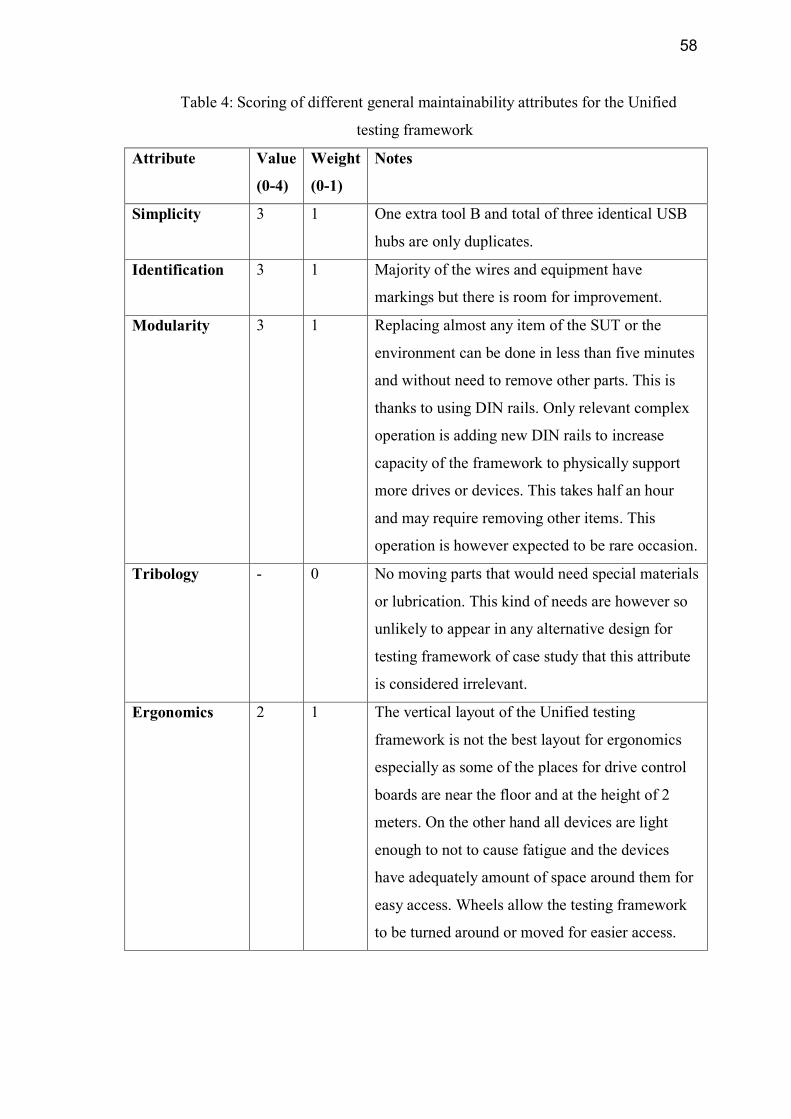
58
Table 4: Scoring of different general maintainability attributes for the Unified
testing framework
Attribute Value
(0-4)
Weight
(0-1)
Notes
Simplicity 3 1 One extra tool B and total of three identical USB
hubs are only duplicates.
Identification 3 1 Majority of the wires and equipment have
markings but there is room for improvement.
Modularity 3 1 Replacing almost any item of the SUT or the
environment can be done in less than five minutes
and without need to remove other parts. This is
thanks to using DIN rails. Only relevant complex
operation is adding new DIN rails to increase
capacity of the framework to physically support
more drives or devices. This takes half an hour
and may require removing other items. This
operation is however expected to be rare occasion.
Tribology - 0 No moving parts that would need special materials
or lubrication. This kind of needs are however so
unlikely to appear in any alternative design for
testing framework of case study that this attribute
is considered irrelevant.
Ergonomics 2 1 The vertical layout of the Unified testing
framework is not the best layout for ergonomics
especially as some of the places for drive control
boards are near the floor and at the height of 2
meters. On the other hand all devices are light
enough to not to cause fatigue and the devices
have adequately amount of space around them for
easy access. Wheels allow the testing framework
to be turned around or moved for easier access.

59
Standardization 4 1 Most of the items are standard items available on
the market. The few exceptions are ABB’s own
products tightly related to SUT that can be
expected to be in production or have compatible
successors during the lifetime of the Unified
testing framework
Failure watch 2 1 PLC, PC and Mac have good failure diagnostics.
USBHub and Ethernet switch have very limited
diagnostics.
Relation with
manufacturer.
- 0 Not taken into consideration because the designer
and assembler of the Unified testing framework
being a thesis worker.
Form the table 4 it can be calculated that the general maintainability indicator for
prototype of Unified testing framework is 17
6≈ 2,83. Considering that 0 is very bad
maintainability and 4 very good, the result of 2,83 is enough to validate the hardware
maintainability of the Unified testing framework. To improve the score the most
significant places to improve are ergonomics and failure watch attributes. Of these the
ergonomics is more difficult to tackle because wall like physical layout is one key
element for high score for modularity attribute.

60
7.3 Performance efficiency
Performance efficiency is measured as the performance relative to the amount of
resources used under stated conditions [4]. For the testing frameworks this can be
understood as the speed at which tests are run in relation to the resources bound in the
testing framework.
7.3.1 Current performance
The time that it takes to run tests for one GUI tool against one drive depends on the tests
to be run, which depend on GUI tool, the variant of the tool and the drive against which
the tests are run as can be seen from the table. For easy reference the table 5 lists
average time for test runs for each GUI tool against one average drive. The times are
basically the same as in the original testing frameworks. Thus it can be concluded that
the absolute speed at which the tests are run has not changed.
Table 5: Average test run times for each GUI tool against and average drive
Tool Average time of test runs
Tool A (all features variant) 2 hours 30 min
Tool A (limited features variant) 1 hour 30 minutes
Tool B (any variant) 3 hours
Tool C (Android) 30 minutes
Tool C (iOS) 30 minutes
Total time 8 hours
On the other hand the Unified testing framework can only execute tests runs for one
GUI tool at a time despite. It also contains same amount of devices as the original
testing frameworks combined if the savings from avoiding duplicate drives are
excluded. Although the savings by avoiding duplicate drives are notable, the savings are
heavily dependent on how many drives the Unified testing framework can practically
support.

61
The physical layout does not cause problems. The Unified testing framework can
support up to 16 Drives. This is more than enough because 9 drives is more believable
maximum amount of drives that will ever be needed.
Instead of physical restrictions the limitation for the saved resources is the time.
Running tests for three drives against all GUI tools according to table 4 takes 24 hours.
This number is not exact as some drives should be tested against at least two tool B
variants and the times of table 5 do not include drive firmware updates. Nevertheless the
question is whether this amount is enough. This is a difficult question. In the original
testing frameworks there would be a total of nine drives instead of three and drives are
more resource intensive than GUI tools. Despite these cost savings I would estimate the
performance of the prototype to be slightly lower compared to original testing
frameworks. The following chapter considers how the performance could be improved.
7.3.2 Performance limitations
The performance in the Unified testing framework is limited by four factors, which each
have different sized effect.
1. How fast the testing framework can run individual tests
2. How fast the next test can be run after previous test ended
3. How many tests can be run at the same time.
4. The time required for firmware updates
Of these limitations the first two are caused by the used SUT and test suite. All
three low level test runners execute the tests without significant delays. Instead all the
significant and systematic delays in the tests are caused by situation where the tests wait
one or more of the items of SUT to do their job such as situations where test is waiting
for GUI tool to connect to drive. Only way to get around this problem would be to use
virtual drives and virtual variants of tool B but as noted in chapter 6.2.1 no applicable
virtual variants of these exists as of yet.
The third aspect, how many test can be run at the same time, is the most crucial
when it comes performance. At the moment only one test can be run at the time. The

62
root cause of this is the fact that the panel bus protocol does not work if two Control
panels are connected to the panel bus at the same time because both of them would try
to be the master of the bus. In Unified testing this multiple masters problem is solved
using a simple method. In this method PLC or more exactly the Configuration manager
program allows only one control panel. Thus only one GUI tool is allows to be
commanding the drives at a time as discussed in chapter 6.2.3. Thus the non-selected
tool Bs are physically prevented from being connected to the drives that are selected.
To improve from this is not simple if the current technology of relays with only two
outputs is used. It also becomes more difficult the more combinations are wanted
especially if possibility to create any combination is not wanted to be lost. This can be
easily seen by considering following example of trying to allow two simultaneous tests
to be run while not losing possibility to connect any GUI tool to any drive. To make this
work conveniently the relays would have to have three outputs. One for device being
selected to group 1, one for being selected to group 2 and the last output is required for
being selected to not to be connected. Getting around this problem is possible by using
only relays with two output states by chaining the relays but this will mean rather
complex wiring and large amount of relays. However even this doubling of performance
would make the performance efficiency of the Unified testing framework very good.
Despite the problems with scalability of relay logic it is difficult to see how this
problem could have been solved in any other way that would have been readily
available. For example virtual devices in SUT such as virtual drives would have made
this problem nonexistent but no virtual alternatives were available. Another solution
could have been that the communication from the drives and other devices would have
been read by a software on PC, which then would have redirected the messages to
correct recipients by programmatically selecting correct PC output ports. This was
however not supported by the panel bus protocol. It would have also caused some level
of delay to the communication which some developers considered possibly harmful for
stability of the testing framework.
The fourth aspect, firmware updates takes only 15 minutes for a drive. Thus it is not
as important as aspect 3 but this time can shortened if needed. One possibility would be
lessen the frequency of updating the firmware but this would not be a good solution
because that might mean that some days are spent testing with obsolete firmware.

63
Second possibility would be to make the firmware update happen when the device
is not under test. This would otherwise be the best solution but the problem is that the
current environment only allows one tool B to be to PC at a time through USB, which is
used for firmware updates. This only panel is all the time in active use either by tests of
Tool A, B or C. Solving this would require reconfiguring the wiring to allow multiple
panels to be connected at the same time but this would be difficult due to issues
discussed already for performance limitation three.
Third possibility to get around the firmware updates taking time is to implement
such automation scheme that would update the firmware only when there actually is a
new firmware available. This could be as simple as one Jenkins build that checks daily
if new files have been uploaded to agreed location.

64
8 Conclusions and thoughts
The discussion in the chapter 7 has shown that the Unified testing framework has
achieved the goals for coverage and maintainability with good grades. The performance
efficiency on the other hand needs improvements. Luckily the bottlenecks for this were
quickly found out and the identified solutions offer significant performance
improvements. When these improvements are made it is sure that the Unified testing
framework will also have good performance efficiency.
During the work it came evident that in order to create a successful testing
framework the most important needed aspect is not the theoretical knowledge on the
testing frameworks but instead the knowledge on the already existing testing
frameworks and especially the SUT. The reason for this was based on two things. First
one is that in the thesis work there already existed testing frameworks for the SUT. This
in combination with limited time reduced the possibilities to change the old test suites
and thus the framework created for testing the SUT.
The knowledge on the SUT proved important also because the SUT itself very
often limited the practical options from many to only few. This was especially true for
the embedded devices and for the aspects related to communication between the
devices. Thus in order avoid bad design decisions, the knowledge on the SUT was
paramount. When there was personal lack of knowledge on the SUT then asking the
developers proved vital. Another lesson to be learned from this is that if testing is
considered important, a good testability should be a requirement when designing any
device or software instead of testing being an afterthought.
Like so often in science and technology, no testing framework is ever final because
the world around and thus the SUT keeps evolving. Thus the many suggestions in the
theory section shall be kept in mind as possible improvements for the Unified testing
framework or when creating testing frameworks for completely new devices. Especially
the idea on the virtual drive should be seriously considered as it would have made
solving the issues of varying SUT and performance trivial in addition to its benefits
outside of the scope of testing.

65
9 References
[1] A. Cervantes, "Exploring the use of a test automation framework," in Aerospace
Conference, 2009 IEEE, 2009, pp. 1-9.
[2] Mao Ye, Wei Dong and Yindong Ji, "A new concurrent test framework for
distributed hardware-in-the-loop simulation test system," in Software Engineering and
Data Mining (SEDM), 2010 2nd International Conference On, 2010, pp. 5-10.
[3] Feng Zhu, S. Rayadurgam and W. -. Tsai, "Automating regression testing for real-
time software in a distributed environment," in Object-Oriented Real-Time Distributed
Computing, 1998. (ISORC 98) Proceedings. 1998 First International Symposium On,
1998, pp. 373-382.
[4] Anonymous "Software and systems engineering Software testing Part 1:Concepts
and definitions," Iso/Iec/Ieee 29119-1:2013(E), pp. 1-64, 2013.
[5] ABB, "What is a variable speed drive",
http://www.abb.com/cawp/db0003db002698/a5bd0fc25708f141c12571f10040fd37.aspx
, Referenced 21.5.2016.
[6] ABB Drives, "Technical Guide no. 4 Guide to Variable Speed Drives", 2011.
[7] R. Hametner, D. Winkler, T. Ostreicher, S. Biffl and A. Zoitl, "The adaptation of
test-driven software processes to industrial automation engineering," in Industrial
Informatics (INDIN), 2010 8th IEEE International Conference On, 2010, pp. 921-927.
[8] M. S. AbouTrab, M. Brockway, S. Counsell and R. M. Hierons, "Testing Real-Time
Embedded Systems using Timed Automata based approaches," J. Syst. Software, vol.
86, pp. 1209-1223, 5, 2013.

66
[9] Yepeng Yao and Xuren Wang, "A distributed, cross-platform automation testing
framework for GUI-driven applications," in Computer Science and Network
Technology (ICCSNT), 2012 2nd International Conference On, 2012, pp. 723-726.
[10] J. Vain and E. Halling, "Constraint-based test scenario description language," in
Electronics Conference (BEC), 2012 13th Biennial Baltic, 2012, pp. 89-92.
[11] Yongfeng Yin and Bin Liu, "A method of test case automatic generation for
embedded software," in Information Engineering and Computer Science, 2009. ICIECS
2009. International Conference On, 2009, pp. 1-5.
[12] D. Winkler, R. Hametner, T. Ostreicher and S. Biffl, "A framework for automated
testing of automation systems," in Emerging Technologies and Factory Automation
(ETFA), 2010 IEEE Conference On, 2010, pp. 1-4.
[13] J. S. Keranen and T. D. Raty, "Model-based testing of embedded systems in
hardware in the loop environment," Software, IET, vol. 6, pp. 364-376, 2012.
[14] M. Dhingra, A. Arora and R. Ghayal, "Achievements and challenges of model
based testing in industry," in Software Engineering (CONSEG), 2012 CSI Sixth
International Conference On, 2012, pp. 1-5.
[15] M. P. E. Heimdahl, "Model-based testing: Challenges ahead," in 29th Annual
International Computer Software and Applications Conference (COMPSAC'05), 2005,
pp. 330 Vol. 2.
[16] S. Kandl, R. Kirner and P. Puschner, "Development of a framework for automated
systematic testing of safety-critical embedded systems," in Intelligent Solutions in
Embedded Systems, 2006 International Workshop On, 2006, pp. 1-13.
[17] J. Hansel, D. Rose, P. Herber and S. Glesner, "An evolutionary algorithm for the
generation of timed test traces for embedded real-time systems," in Software Testing,

67
Verification and Validation (ICST), 2011 IEEE Fourth International Conference On,
2011, pp. 170-179.
[18] T. Yu, A. Sung, W. Srisa-an and G. Rothermel, "An approach to testing
commercial embedded systems," J. Syst. Software, vol. 88, pp. 207-230, 2, 2014.
[19] V. Santiago, W. P. Silva and N. L. Vijaykumar, "Shortening test case execution
time for embedded software," in Secure System Integration and Reliability
Improvement, 2008. SSIRI '08. Second International Conference On, 2008, pp. 81-88.
[20] Litian Xiao, Mengyuan Li, Ming Gu and Jiaguang Sun, "Combinational testing of
PLC programs based on the denotational semantics of instructions," in Intelligent
Control and Automation (WCICA), 2014 11th World Congress On, 2014, pp. 5840-
5845.
[21] A. Bansal, M. Muli and K. Patil, "Taming complexity while gaining efficiency:
Requirements for the next generation of test automation tools," in Autotestcon, 2013
Ieee, 2013, pp. 1-6.
[22] P. Iyenghar, E. Pulvermueller and C. Westerkamp, "Towards model-based test
automation for embedded systems using UML and UTP," in Emerging Technologies &
Factory Automation (ETFA), 2011 IEEE 16th Conference On, 2011, pp. 1-9.
[23] A. K. Jha, "Development of test automation framework for testing avionics
systems," in Digital Avionics Systems Conference (DASC), 2010 IEEE/AIAA 29th,
2010, pp. 6.E.5-1-6.E.5-11.
[24] N. Bartzoudis, V. Tantsios and K. McDonald-Maier, "Constraint-based test-
scheduling of embedded microprocessors," in Micro-Nanoelectronics, Technology and
Applications, 2008. EAMTA 2008. Argentine School Of, 2008, pp. 29-32.

68
[25] Ying-Dar Lin, E. T. -. Chu, Shang-Che Yu and Yuan-Cheng Lai, "Improving the
Accuracy of Automated GUI Testing for Embedded Systems," Software, IEEE, vol. 31,
pp. 39-45, 2014.
[26] M. Bajer, M. Szlagor and M. Wrzesniak, "Embedded software testing in research
environment. A practical guide for non-experts," in Embedded Computing (MECO),
2015 4th Mediterranean Conference On, 2015, pp. 100-105.
[27] J. Gaardsal and J. Sønderskov. "Automated GUI testing on low-resource embedded
systems", M.Sc. thesis, Aarhus University, Aarhus, 2014, Denmark.
[28] Hyungkeun Song, Seokmoon Ryoo and Jin Hyung Kim, "An integrated test
automation framework for testing on heterogeneous mobile platforms," in Software and
Network Engineering (SSNE), 2011 First ACIS International Symposium On, 2011, pp.
141-145.
[29] Li Feng and Sheng Zhuang, "Action-driven automation test framework for
graphical user interface (GUI) software testing," in Autotestcon, 2007 IEEE, 2007, pp.
22-27.
[30] W. Hargassner, T. Hofer, C. Klammer, J. Pichler and G. Reisinger, "A script-based
testbed for mobile software frameworks," in Software Testing, Verification, and
Validation, 2008 1st International Conference On, 2008, pp. 448-457.
[31] E. Borjesson, "Industrial applicability of visual GUI testing for system and
acceptance test automation," in Software Testing, Verification and Validation (ICST),
2012 IEEE Fifth International Conference On, 2012, pp. 475-478.
[32] K. Kawaguchi, "Meet Jenkins", https://wiki.jenkins-
ci.org/display/JENKINS/Meet+Jenkins, Referenced 22.5.2016.

69
[33] Microsoft, Installing and Configuring Test Agents and Test Controllers, Available:
https://msdn.microsoft.com/library/dd648127%28v=vs.120%29.aspx, Referenced
19.5.2016.
[34] Microsoft, Use UI Automation To Test Your Code, https://msdn.microsoft.com/en-
us/library/dd286726.aspx, Referenced 19.5.2016.
[35] G. Bossert, D. Makarov and M. Baar, "PerfPublisher Plugin", https://wiki.jenkins-
ci.org/display/JENKINS/PerfPublisher+Plugin, Referenced 22.5.2016.
[36] "Nose", https://nose.readthedocs.org/en/latest/#, Referenced 22.5.2016.
[37] Selenium HQ, "Selenium WebDriver",
http://www.seleniumhq.org/docs/03_webdriver.jsp, Referenced 22.5.2016.
[38] "Introduction", http://appium.io/introduction.html?lang=fi. Referenced 25.5.2016.
[39] Xunit: output test results in xunit format.
http://nose.readthedocs.org/en/latest/plugins/xunit.html, Referenced 22.5.2016.
[40] Jesse Glick, "Junit plugin" https://wiki.jenkins-
ci.org/display/JENKINS/JUnit+Plugin, Referenced 22.5.2016.
[41] J. Kauppinen, "A virtual electric drive for offline configuration", M.Sc. thesis,
Helsinki University of Technology, Espoo, Finland, 2012.
[42] Ivo Bellin Salarin, "MSTest plugin", https://wiki.jenkins-
ci.org/display/JENKINS/MSTest+Plugin, Referenced 22.5.2016.

70
[43] P. Moreu De Leon, V. González-Prida Díaz, L. Barberá Martínez and A. Crespo
Márquez, "A practical method for the maintainability assessment in industrial devices
using indicators and specific attributes," Reliab. Eng. Syst. Saf., vol. 100, pp. 84-92, 4,
2012.