Embed Size (px)
Citation preview

NASA TECHNICAL NOTE
co Q N N
I Q :::z: ...... < � < :z:
NASA US-Bv.l c.l
NASA TN ,.. ........
UNIFIED S-BAND TELECOMMUNICATIONS TECHNIQUES FOR APOLLO VOLUME 1 - FUNCTIONAL DESCRIPTION
by John H. Painter and George Hondros Manned Spacecraft Center Houston, Texas NATIONAL AERONAUTICS AND SPACE ADMINISTRATION • WASHINGTON, D. C. • MARCH 1965

TECH LIBRARY KAFB, NM 1 1111 1111111 IIIII IIIII IIIII IIIII 1111 //IIIII 0069093
UNIFIED S-BAND TELECOMMUNICATIONS TECHNIQUES FOR APOLLO
VOLUME I
FUNCTIONAL DESCRIPTION
By John H. Painter and George Hondros
Manned Spacecraft Center Houston, Texas
NATIONAL AERONAUTICS AND SPACE ADMINISTRATION - --
For sale by the Office of Technical Services, Department of Commerce,
Washington, D.C. 20230 -- Price $3.00

Ill
FOREWORD
The Review Copy of this publication was entitled, "The Apollo Unified S-Band Telecomm:unicat;i.ons System - Volume 1", and identified as File Number S-58 by NASA Manned Spacecraft Center. The present publication, under a new title, is nearly identical to the Review Copy with only a few minor changes.
The authors wish to acknowledge the aid and cooperation received in the preparation and review of this document.
w. M. B. L. P. M.
D.
Victor Easterling Martin Randolph Goodwin Brockman
Holcomb
Jet Propulsion Laboratory Pasadena, California
Motorola, Inc. Scottsdale, Arizona

Section
1.0
2.0
TABLE OF CONTENTS
INTRODUCTION . . .
1.1 Objectives of the Report
1.1.1 Volume I . 1.1.2 Volume II. 1.1.3 Volume III
1.2 History of the System
THE BASIC SYSTEM . .
2.1 System Concept
2.1.1 2.1.2
The Basic Spacecraft System The Basic Ground System
2.2 Extension of the Basic System Re�uired to Support the Command Service Module and Lunar Excursion Module . .
2.3 The Ground Network
DETAILED SYSTEM DESCRIPTION
3.1 The Communications Signals
Up-link ( Ground to Spacecraft ) . Down-link (Spacecraft to Ground )
3.2 Signal Transmission Modulation Techni�ues
3.2. 1 3.2. 2 3.2. 3
Up-link. . . . Down-link Signal Design
3.3 Spacecraft Subsystem Configuration
3.3.1 Premodulation Processor 3.3 . 2 Transponder . .
3.4 Ground Subsystems .
3.4.1 3.4.2 3.4.3 3.4.4
General Configuration Antennas . . . . . . •
Microwave Circuitry Reference Channel Receiver
i
Page
2
2
2 2 3
3
6
6
6 7
8 8
10
10
10 10
12
12 12 14
16
16 19
22
22 23 23 24

Section
4.0
5.0
6.0
3.4.5 Angle Channel Receiver 3.4.6 Transmitter . • . . .
3.4.7 Ranging Circuitry 3.4.8 Demodulation Circuitry 3.4.9 Premodulation Circuitry 3.4.10 Acquisition and Programing Circuitry 3.4.11 Ground System Peripheral Equipment
SYSTEM OPERATIONAL TECHNIQUES
4.1 Ranging and Spacecraft Acquisition
4.1.1 A Physical Explanation of the Ranging Process 4.1.2 An Explanation of Acquisition
4.2 Lunar Mission Communications Requirements
4.2.1 Pre-Launch .
4. 2. 2 Launch . . . 4.2.3 Earth Orbit 4.2.4 Translunar Injection 4.2.5 Spacecraft Transposition and LEM Checkout 4.2.6 Earth-Lunar Coast. 4.2.7 Lunar Orbit . . . . 4.2.8 Lunar Landing 4.2.9 Moon-Earth Injection and Coast 4. 2. 10 Reentry. . . . . . .
4. 3 System Operation for a Nominal Lunar Mission
4.3.1 4.3.2 4.3.3 4.3.4 4.3.5 4.3.6 4.3.7 4.3.8 4.3.9
Pre-launch . . . . . . Launch . . . . . . . . Earth-Orbit Insertion Earth-Orbit Trans-Lunar Trajectory Injection Transposition and LEM Check-out Translunar Orbit . . . . • . . . Lunar Orbit . . . . . . . . • .
Lunar Landing, Surface Operations and Rendezvous . . . . . .
4.3.10 Earth Trajectory Injection and Coast 4.3.11 Atmospheric Reentry
REFERENCES
TABLES .
FIGURES
ii
Page
25 25 26 28 31 31 31
34
34
34 36
37
37 38 38 38 38 38 38 39 39 39
39
39 39 40 40 40 40 41 41
41 42 42
43
44
51

UNIFIED S-BAND TELECOMMUNICATIONS TECHNIQUES FOR APOLLO
VOLUME I
FUNCTIONAL DESCRIPTION
By John H. Painter and George Hondros Manned Spacecraft Center
SUMMARY
This document is a functional description of the intended configuration and operation of the Apollo Unified S-band Telecommunications and Tracking System. In particular, this description applies to the link between the command-service module and the ground tracking station. The lunar excursion module-to-ground link is similar, and an e�uivalent description applies.
The document begins with a short resume of the system's developmental history. Then the basic spacecraft and ground system concept are simply explained. Following are detailed descriptions of the communications signals, modulation techni�ues, and subsystem configurations. The document concludes with explanations of system operational techni�ues .

1 . 0 INTRODUCTION
1 . 1 Objectives of the Report
The Unified S-Band Telecommunications and Tracking System under development for the Apollo lunar missions is not now well documented. Although some documentation on the individual subsystems exists, there is no complete system documentation which provides a reader with the basic system design, capabilities, operation, and limitations. This report is intended to provide such system documentation for the system in its current state of development and is divided into three volumes because of the system complexity.
Detailed description of other elements that may feed into the present system but are not directly developed by MSC is planned to appear in later volumes of this report or in appropriate reference materials as they are developed.
l.l.l Volume I Volume I provides a simplified functional description of the configuration
and operation of the communication and tracking system to be used in the lunar Apollo missions. The spacecraft S-band subsystems for the command-service module ( CSM ) and lunar excursion module ( LEM) are very similar in a system sense. Both vehicles will, in fact, be supported by the same type of ground station communication e�uipment. Therefore, the basic spacecraft description, given here, is for the CSM, with the minor differences of the LEM subsystem pointed out. The basic system modulation techni�ues and operational concepts are described.
At the time Volume I was prepared, the CSM spacecraft S-band subsystem
was being redesigned to accommodate additional communication re�uirements, insure e�uipment reliability, and insure compatibility with the ground subsystem. The spacecraft subsystem configuration chosen to be described in this volume is one which resulted from detailed technical discussions between Manned Spacecraft Center, Jet Propulsion Laboratory, NASA Head�uarters, Goddard Space Flight Center, and associated contractors. Although the authors feel that this configuration best meets the presently defined communication re�uirements and provides more fl�ibility than other presently proposed configurations, it is possible that the final spacecraft S-band e�uipment may differ slightly (at the module level ) from the one described. It is not expected that the basic design philosophy or operation of the spacecraft S-band subsystem will depart appreciably from that described.
At the time of preparation of Volume I, the ground subsystem demodulators were functionally specified, but not designed. The authors have treated the set of demodulators which, in their judgment, best satisfy the re�uirements •
.
1 . 1 . 2 Volume II Volume II is a detailed mathematical analysis of the communication and
tracking channels of the system. E�uations in generalized parameters are derived which may be used either to design the communication channels or to
2

analyze existing designs. The equations are sufficiently general that changes of the type referred to in section 1 .. 1.1 may be easily treated. Basic assumptions made in the derivations are plainly stated so that the validity of the channel models may be easily inferred.
1.1.3 Volume III Volume III is a tabulation of performance data or circuit margins for
each channel of the system. The calculation of these circuit margins is based on the theoretical analysis presented in Volume II. The circuit margins in Volume III allow inference of the quality of the various system channels during nominal as well as non-nominal modes of transmission of the spacecraft and ground systems.
1.2 History of the System
The present configuration of the Unified S-Band has evolved from earlier equipment. It is therefore important to acquaint the reader with the history of the system. The Mercury spacecraft was provided with many electro-magnetic transmitting and receiving systems. These systems operated at seven discrete frequencies within five widely separated frequency bands. The systems used on the Mercury spacecraft were:
l. HF voice transmitter and receiver
2. UHF voice transmitter and receiver
3 . VHF telemetry transmitter no. l
4 . VHF telemetry transmitter no. 2
5- C-band transponder
6. UHF command receiver
7· S-band transponder ( pulse) To complement the spacecraft systems, a number of ground stations, strate
gically located about the globe, were provided with systems compatible to those in the spacecraft to fulfill the communications and tracking requirements for the Mercury missions. The spacecraft and ground systems used in the Mercury Project performed satisfactorily. As a result, it was planned that the great majority of these systems should be used in the Gemini Project, with, perhaps, some systems modifications made to provide better performance or power and weight savings in the Gemini spacecraft.
When the Apollo Project was initiated, it was stipulated that as much as possible of the existing Mercury ground network and spacecraft systems be used. In addition to these systems, it was conceived that a transponder should be included in the spacecraft to perform the ranging operation at lunar distances. The transponder was also to be used for transmission of voice and telemetry at lunar distances. Since the transponder design chosen was compatible with the
3

II •• 11111·1·1·. II I 111.11.11···---··· ···- 1111 .I I I I I I I I .. .. .. .... .. " ·-· I ' ' ... • • • ·- . ... . . . .. -.... . .... ---
Deep Space Instrumentation Facility ( DSIF), established by the Jet Propuls ion Laboratory ( JPL), the JPL techni�ue (pseudo-random code ranging) was chosen by NASA to perform ranging . Thus, for the deep space phase of communications for the lunar mis s ion, the JPL transponder was to perform the communication and tracking functions using three deep space stations , closely resembling the JPL design . For the near- earth phase, however, the VHF, UHF, and C-band Geminitype e�uipments were to be used to perform the communications and tracking
functions . A study1 conducted by JPL, however, indicated that "under worst conditions " the deep space stations might not ac�uire the spacecraft at alti-tudes lower than 10, 000 nautical miles2• In addition, computations made by the contractor and MSC indicated that the VHF and UHF systems range capability would b e less than 10, 000 nautical miles .
, During the early phases of spacecraft sub systems design, performed by the contractor, it was realized that a problem with the spacecraft weight would arise, s ince the near- earth phases of the miss ion re�uired a number of different spacecraft transmitters and receivers, as well as their back-ups . Because of this realization, the contractor suggested to NASA that additional cons ideration should be given to the spacecraft weight problem, and that perhaps some other communications and tracking system could b e used during the various nearearth phases of the Apollo lunar miss ions .
As a result of the foregoing cons iderations , a meeting was held at the Office of Tracking and Data Ac�uisition Systems ( OTDA) in Washington, D . C . in December 1962 . At this meeting OTDA presented plans for a ground network us ing a unified S-band carrier system to representatives of various NASA centers , including JPL and MSC . The ground portion of the system was to consist of three stations having 85- foot Cassegrain feed antennas for deep space communications and tracking ( separate from those of JPL), and a number of stations with 30-foot Cas segrain feed antennas to perform communications and tracking during the near- earth phas es of the Apollo lunar mis s ions . This proposed ground network not only would increase the range capabilities for near- earth communications and tracking, but would also allow transmis s ion from the spacecraft during both near- earth and deep-space phases to b e performed by one transmitter, thus eliminating all the VHF, C-band and UHF systems and their back-ups, and conse�uently reducing the spacecraft weight .
The philosophy of us ing the unified S-band system for communications and tracking at near- earth and in deep space has been ac cepted . As a result, the ground network re�uir ed for the support of lunar mis s ions is presently being implemented under a contract from the Goddard Space Flight Center .
1EPD-29 - Estimated 1963- 1970, Capability of the Deep Space Instrumentation Facility for Apollo Project, JPL, Pasadena, California, 2-l- 62 .
2The altitude of 10, 000 nautical miles was calculated on the basis of the three JPL DSIF stations located at Goldstone, California, Johannesburg, Union of South Africa, and Woomera, Australia .
4

The Apollo unified 8-band system has not yet been evaluated in the laboratory, s ince the hardware de s ign and fabrication has not been completed. Plans have been prepared, however, by the Manned Space craft Center for early and continuing laboratory te sting as well as flight qualification of the system.
5
2 . 0 THE BASIC SYSTEM
2 . 1 System Concept
The primary concept underlying the Apollo S-band telecommunications system was originally that all communications and data transfer between spacecraft and ground should be made using one common set of equipment and one radio frequency carrier for transmission. Because of various historical and mechanical reasons, this concept has not been fully implemented in the Apollo system. The historical reasons have been mentioned in the previous section. Because of the ground requirement that the spacecraft transmit a stable carrier spectral line, phase-coherent with the up-link carrier, to enable two-way Doppler tracking, ranging, and ground antenna pointing, narrow deviation phase modulation has been implemented for most of the spacecraft transmission. Those information functions requiring a large modulated bandwidth are modulated directly on the carrier while other, less wide, functions are first modulated onto subcarriers. Since the range code and television signals transmitted by the Apollo spacecraft both require large modulated bandwidths, and, in some instances, will be transmitted simultaneously, it was necessary to place them on separate carriers, using phase modulation for the first and frequency modulation for the second. Aside from this exception, however, the basic concept of one carrier and one set of equipment has been closely approached in the Apollo system. Failure and redundancy considerations have, of course, required duplicate standby equipments, both in the spacecraft and on the ground. The system described in this report will be used in the translunar and lunar phases of the Apollo mission and during the injection phase from earth orbit to lunar transfer trajectory. It is planned that the system will be used in the earth orbital mission phases also.
The heart of the unified Apollo system is the pseudo-random code ranging subsystem developed by Jet Propulsion Laboratory. This system uses a groundbased transmitting and receiving station working in conjunction with a spacecraft transponder. A pseudo-random code is phase modulated on an S-band carrier at the ground and transmitted to the spacecraft. The code modulation is recovered in the transponder and retransmitted to the ground station on a different S-band carrier which is phase coherently generated from the up carrier. At the ground station the time difference between the transmitted and received code gives a measure of the spacecraft range.
2. 1 . 1 The Basic Spacecraft System Neglecting redundancy, the basic spacecraft system is shown, highly
simplified, in figure 1. The system is composed of a premodulation processor, transponder, final amplifier and associated microwave circuitry, high-gain antenna and omnidirectional antenna. This system diagram is later expanded (section 3 . 3 ) to show the means for obtaining switchable redundancy and simultaneous PM-FM operation.
The premodulation processor accepts voice, PCM telemetry, biomedical data, television, and emergency key signals from the spacecraft for transmission to the ground. It also recovers the voice and up-data signals received from the ground. 6
·-·---·---·-·" ········-·-" ·····-------·-------·

The CSM transponder is basically a narrow band PM receiver, narrow band PM transmitter exciter, and wide band·FM transmitter exciter . The LEM transponder, however, does not contain an FM exciter since it is not required for the LEM to transmit FM and PM information, s imultaneously. The transponder feeds and is fed by a package containing final amplifiers and microwave switching and diplexing circuitry. The microwave circuitry feeds the two spacecraft antennas which are manually selectable. The PM receiver has a local oscillator, phase locked to the received carrier, which provides the frequency and phase reference for the PM transmitter exciter . �ne FM transmitter exciter has its own separate oscillator . The PM receiver is used at all times to receive from the ground. The PM exciter is used at all times to transmit to the ground. The FM exciter is used only when transmission of FM data is required.
2 . 1 . 2 The Basic Ground System Again neglecting redundancy, the basic ground system is shown, highly
simplified, in figure 2 . The system is composed of a high-gain main antenna, wide-beam acquisition antenna, microwave circuitry, a main reference channel receiver, acquisition reference channel receiver, two main angle channel receivers , two acquis ition angle channel receivers, a transmitter, data demodulation circuitry, ranging circuitry, premodulation circuitry, acquisition and programing circuitry, data handling equipment, and peripheral equipment .
The acqui sition channels , transmitter, and acquisition antenna are used initially to acquire the spacecraft signal . This operation consists of a search in angle with the acqui sition antenna and a s earch in frequency with the acquisition reference channel receiver for the central PM carrier component of the spacecraft signal . The ground receiver local oscillator phase locks to the received carrier, thus activating the angle channels . When the acquisition antenna is sufficiently well aligned, the main antenna, which is physically tied to the acquis ition antenna, acquires the spacecraft carrier . The main reference channel receiver is then phase-locked and the main angle channels become effective. The drive for the antenna s ervos is then switched from the acquisition to the main angle channels .
The ranging circuitry contains digital equipment for generating the various range codes and range measurements , Doppler measuring circuitry, and a range code receiver which is fed by the reference channel 10-megacycle IF output s . The ranging circuitry feeds the range code to the transmitter phase modulator, where it is effectively summed with other up-going data from the premodulation circuitry.
The data demodulator, as shown in figure 2, accepts PM data from the main reference channel receiver and FM data from the acquisition reference channel. Since the two reference channel receivers are identical, the acquisition reference channel is available, after completion of acquisit ion, for the reception of other data, namely FM. The data demodulation and ranging equipment both feed the data handling equipment . The data handling equipment also feeds the premodulation equipment .
7

The acquisition and programing circuitry plays an ess ential role with the rest of the equipment . The ranging proces s es are automated, and are digitally programed in response to analog measurements on various parts of the equipment . The programing circuitry contains special purpos e digital computing equipment and analog-to-digital converters . Additional peripheral equipment, not shown in figure 2, forms another part of the basic ground system. This equipment is treated in s ection 3 . 4.
2 . 2 Extension of the Basic System Required to Support the Command/Service Module and Lunar Excursion Module
The Apollo lunar mis sion uses two spacecraft , the command/service module (CSM ) and lunar excursion module (LEM). The CSM communications system is active throughout the mis sion, from prelaunch through reentry and landing. The LEM communications system is active mainly in the region of the moon. The mission communication requirements for the two spacecraft are treated in detail in s ection 4 . 2 .
The fact that there are two spacecraft, each having its own S-band system, complicates the ground station. Figure 3 shows a configuration for a ground station having a full duplicate ability to range simultaneously and communicate simultaneously with both spacecraft . Thi s configuration implies that both spacecraft remain within the beamwidth of the high-gain ground antenna and that antenna pointing is performed on only one of the spacecraft . It is s een that to the basic ground station have been added two reference channel receivers , one data demodulator, one set of ranging circuitry, one transmitter and one s et of premodulation circuitry. It should be understood that the capability of the data handling and acquisition and programing eircuitry is also expanded over the basic system. Figure 3 still ignores redundancy, although the ability to switch data demodulators and ranging circuitry from one reference channel to another implies redundancy of a sort .
Functionally, the two spacecraft S-band systems are alike, although there may be differences in physical packaging and available output power levels . These differences are discussed further in the detailed system description, s ection 3 . 3 .
2 . 3 The Ground Network
There are three types of S-band ground stations ; the deep- space stations, injection and transposition gap-filler stations , and earth-orbital stations . The type s of stations differ in the sizes of their antennas and whether they have single or dual tracking capability.
The three deep- spac e stations have 85-foot diameter antennas and full dual tracking and communication capability. Thes e stations will be located at Goldstone, California; Madrid, Spain; and Canberra, Australia. Following the inj ection into lunar transfer trajectory and during the LEM transposition phases of the Apollo lunar mis sion, it is pos s ible that the spacecraft will not have been acquired by a deep- space station . This poss ibility exists becaus e the spacecraft, at the beginning of injection, is at a relatively low altitude
8

(100 nautical miles ) . Depending on the geographical relation of the injection point to the nearest deep-space station, the spacecraft may have to climb s everal thousand miles in altitude before becoming vis ible.
Because of this poss ible gap in coverage, several injection gap-filler stations , number and location now unknown, will be used to supplement the deep-space stations for those missions where deep- space station ac�uisition i s delayed. Thes e stations will have 30-foot antennas and dual data communication capabilities . The S-band ground stations to be used in the earth-orbital mis sion phases will have 30-foot antennas and s ingle rangin� and communications capabilities . The locations of the stations will be such as to provide good coverage of Apollo earth orbits, in conjunction with the gap-filler stations .
9

3 . 0 DETAILED SYSTEM DESCRIPTION
3 . 1 The Communications Signals
The following section de scribe s the various communication, data, and ranging s ignals which serve as inputs to the system, either on the ground or in the spacecraft . The signals are des cribed as they e xist in their unmodulated or baseband form. The modulated s ignals are treated in section 3 . 2 .
3 . 1 . 1 Up-link (Ground to Spacecraft )
3 . 1. 1. 1 Range code . - One of the most important s ignals generated by the ground station is the range code , used to dete rmine the radial range between ground station and spacecraft . This code is a continuous running binary waveform which progre sses at a nominal rate of a million bits per second, being generated from s 496-kilocycle clock signal. Being one of a class of codes known as pseudo-random, this code has a bas ic period of about 5 . 4 seconds . This period insures that the code doe s not repeat for 5 . 4 million bit periods . A period of this length is reQuired so that the code will not recycle during the time of propagation from earth to moon and back .
The transmitted code , which is generated by digital logic circuitry, is a Boolean combination of four shorter code s and the digital clock s ignal (a 496-kc sQuare wave ) . For general information the combining function is :
Code = (x . c � v (X . [ (a . b v b . c v a . c ) 0 c l J} Where the dot indicate s the Boolean "and" , the v indicate s the Boolean "or", the 0 indicate s the Boolean "exclusive or" , and the bar indicates the Boolean "not'. The lengths of the code components in bit periods are given in table I . For detailed information on the generation of this code , see reference 1 .
3 . 1 . 1 . 2 Up-Data . - It is reQuired that a digital up-data link be available to transmit to the spacecraft (both CSM and tEM) either up-dating information for the on-board computer or real-time or stored-program commands . The signal brought in to the S-band eQuipment is derived from a Gemini-type Digital Command System (DCS) . This s ignal is a composite waveform consisting of a 1-kilocycle s inusoid summed with a 2-kilocycle s inusoid which has been phaseshift keyed by a 1-kilobit digital signal . The digital s ignal is a bas ic 200-bit information s ignal, sub-bit encoded, 5 bits for 1 .
3 . 1 . 1 . 3 Voice . - Voice transmis sion is also reQuired t o the spacecraft . The baseband voice s ignal is simply an analog waveform with most of its energy lying between 300 and 2 , 300 cycle s per second . This s ignal originate s from the various channels in the ground station.
3 . 1. 2 Down-link ( Spacecraft to Ground )
3 . 1 . 2. 1 Range code . - The range code s ignal, recovered in the spacecraft for retransmission to the ground, is approximately the same as that generated
10

II
on the ground, except that it is contaminated with noise and two up-link subcarriers ( s ection 3 . 2 ) . The code is running at a slightly different rate due to Doppler effects .
3 . 1 . 2 . 2 �uls e-code-modulated telemetry. - The primary spacecraft telemetry signal is binary PCM {non-return to zero) having either a 51. 2-kilobit or 1 . 6-kilobit informat ion transmis sion rate. The bas ic onboard generated telemetry clock fre�uency is 512 kilocycles .
3 . 1 . 2 . 3 Voice. - The baseband voice signal is much like the ground station voice signal. Clipping and filtering is employed to keep the average voice level high and most of the power between 300 and 2 , 300 cycles . The voice signal originates from the astronaut 's microphone or the AM relay receiver used during extravehicular astronaut activities .
3 . 1 . 2 . 4 Biomedical telemetry. - Biomedical data from the astronauts is routed through the PCM t elemetry when the astronauts are in the spacecraft . When an astronaut is out s ide the spacecraft , either in space or on the surface of the moon, a special s et of biomedical telemetry channels is provided . Seven low fre�uency subcarriers in the astronaut's suit communications package are fre�uency modulated with the biomedical measurements . The modulated subcarriers are summed and amplitude modulated on a VHF carrier for relay back to the parent spacecraft . At the spacecraft the AM signal is demodulated and the summed fre�uency-modulated subcarriers are recovered . This recovered signal forms the baseband input to the S-band system. The center fre�uencies and channel information of the various biomedical subcarrier channels are given in table II .
3 . 1 . 2 . 5 Television. - During certain mission phases the spacecraft will transmit television to the ground . Because of spacecraft power limitations the television picture will not be of the usual broadcast �uality. The television signal is analog, having a basic picture format of 10 frames per s econd, 320 lines per frame, with an aspect ratio of 4:3 . The resolution is further limited by 500-kilocycle baseband low pas s filtering . Amplitude synchronization will be used with the synchronizing level 30 percent above the black level .
3 . 1. 2 . 6 Emergency voice. - A capability is re�uired for succes sful voice communication with the ground in the event of failure of the spacecraft highgain antenna or final amplifier, but not both. The emergency voice bas eband signal is the normal voice, routed through a different channel.
3 . 1 . 2 . 7 Emergency key. - For a last-resort communication capability the astronauts may use hand-keyed Morse code. The bas eband key signal is an on-off d-e voltage obtained by keying the spacecraft 28-volt battery.
3 . 1 . 2 . 8 Recorded PCM telemet�. - PCM telemetry at either a 1 . 6 kbs rate or 51 . 2 kbs rate may be recorded when neces sary. When the recorded telemetry is played back into the transmis sion channel the playback signal has a nominal 51. 2 kbs rate with, perhaps , some "wow" and "flutter" due to the tape recorder. The playback signal is routed through a different channel than the real-time telemetry.
ll

3 . 1 . 2 . 9 Recorded vo�ce. - The normal clipped voice may be recorded at any time. The recorded voice is played back at a higher rate than the recording rate (greater than 4:1). The playback s ignal occupys a greater bas e bandwidth than the normal voice signal (greater than 9 kc ) due to the high playback rate. The playback signal is routed through a different channel than the real-time voice.
3 . 2 . 1 Up-link
3 . 2 Signal Transmis sion Modulation Techniques
The up-link modulation techniques are simpler, conceptually, than the down-link and so are treated first . The final modulation process on the outgoing carrier i s phase modulation using relatively narrow deviation. Narrow phase modulation is required to insure that a phase stable carrier component arrives at the spacecraft . Since the spacecraft transmis sion carrier is derived phase coherently from the received carrier, it is important that the carrier received at the spacecraft not be allowed to reverse phase for any appreciable length of time due to modulation, since this reversal would cause an error in two-way Doppler tracking between the ground transmitted and received carriers . Narrow phase deviation als o assures that the modulation is concentrated in the first order side product s of the modulated signal . This concentration optimizes the particular reception technique employed in the spacecraft.
The total rms phase deviation on the up-link carrier is kept at about l one radian. For a classical treatment of signal design, see reference 2 .
3 . 2 . 1 . 1 Range code. - The range code, which is a binary analog waveform, is effectively s ummed with the other up-going information and phase modulated onto the carrier .
3 . 2 . 1 . 2 Up-data. - The baseband up-data s ignal is first frequency modulated on a 70-kc subcarrier, then summed with the other up-going information and phase modulated on the carrier .
3 . 2 . 1 . 3 Voice. - The bas eband voice signal is first frequency modulated on a 30-kc subcarrier, then s ummed with the other up-going information and phase modulated on the carrier .
3 . 2 . 2 Down-link The down-link modulation techniques for CSM and LEM are practically
identical . The CSM may transmit on two S-band carriers simultaneously. The LEM, however, may time share one carrier for transmis sion of FM or PM modulation. Considering both spacecraft , three s eparate carrier frequencies may be received at the ground, simultaneously. The various modulation parameters will be treated in the s ection on signal design.
NOTE: 1. The only difference between the up-links for CSM and LEM is the carrier frequency. The modulation techniques are identical . The various modulation parameters are treated in s ection 3 . 2 . 3, Signal Design.
12

There are two final modulation process es in the spacecraft . These proces s es are phase modulation and frequency modulation. Similar to the up-link, a phas e- stable carrier component must arrive at the ground station for use in Doppler tracking and for use by the narrow angle channels which point the ground antenna . This carrier requirement implies narrow phase modulation for some of the information links . In addition, the carrier requirement implies that the LEM can not transmit FM modulation when tracking and ranging is required by the ground. As explained in section 2 . 1, a s eparate frequencymodulated carrier was chosen for the transmi ssion of television and certain other data . Certain of the information signals can be transmitted only in the PM channel� and c ertain other signals can be transmitted only in the FM channel . Some of the information signals can be transmitted in either channel. The combination modes are spelled out explicitly in the signal design section 3 . 2. 3 .
3 . 2 . 2 . 1 �ange code. - The range code, having been recovered in the spacecraft , is effectively summed with the other PM channel information and phase modulated onto the down carrier . The range code is restricted to the PM channel only.
3 . 2 . 2 . 2 Pul s e code modulated telemetry. - The PCM telemetry signal, binary coded, is first phase modulated on a 1 . 024-mc subcarrier . The modulated subcarrier may then be either summed with PM channel information and phase modulated on the down PM carrier or summed with FM channel information and frequency modulated on the down FM carrier .
3 . 2 . 2 . 3 Voice. - The bas eband voice signal is first frequency modulated on a 1 . 25-mc subcarrier . As with the PCM telemetry subcarrier, the voice subcarrier may be summed with other information and be transmitted through either the PM or FM channel .
3 . 2 . 2 . 4 ]iomedical telemetry. - When employed, the biomedical telemetry baseband signal will fir st be summed with the bas eband voice signal. Then both signals will be frequency modulated on a 1 . 25-mc subcarrier (the voice subcarrier ) . Thi s modulated subcarrier may then be transmitted through either the PM or FM channel.
3 . 2 . 2 . 5 Television. - The baseband televis ion signal is summed with other FM channel information and frequency modulated on the down carrier . Television is restricted to the FM channel only.
3 . 2 . 2 . 6 Emergency voice. - The bas eband voice signal is phase modulated directly on the carrier using a sufficiently narrow deviation to insure the ret ention of a phase-stable carrier-spectral component for ground Doppler track.
3 . 2 . 2 . 7 Emergency key. - The keyed d-e signal is applied to a digital "and" circuit, to which i s also applied the 512-kc square wave from the spacecraft central timing equipment . 'I'he output of the "and" circuit, a keyed 512-kc square wave, is then band-pass filtered to give a keyed 512-kc subcarrier . The keyed subcarrier is phase modulated on the carrier using a narrow enough phase deviation to maximize the first order side product and to insure ret ention of a phase-stable carrier- spectral component for ground Doppler track.
13

3. 2. 2. 8 Recorded PCM _te]-e:r;e_t_rx.- The recorded PCM telemetry signal is bi-phase modulated on a 1.024lnc subcarrier. This is not the same subcarrier used for real-time telemetry. The modulated subcarrier may then be summed with other information and transmitted through either the FM or PM channel. The subcarrier for recorded telemetry cannot be transmitted through the same carrier channel as that carrying the real-time telemetry subcarrier.
3· 2. 2. 9 Recorded voice.- The recorded voice signal is freq_uency modulated on a 1.25 me subcarrier. This is not the same subcarrier used for real-time voice. Because of base-bandwidth considerations, the relayed EVA biomedical data cannot be summed with recorded voice. The modulated subcarrier may be summed with other information and transmitted through either the PM or FM channel. As with recorded telemetry, recorded voice and real-time voice cannot be transmitted through the same carrier channel.
3.2.3 Signal Design It has been stated previously (sec. 3.2.2) that for the down link certain
information functions are restricted to PM only or FM only, while some functions can be transmitted either way. There are many possible combinations of transmissions. The choice of the various modulation parameters for these combinations is referred to, here, as signal design. At this time, first cut signal design and optimization for both the up and the down links have been performed by the prime contractors for CSM and LEM, respectively.
3.2.3.1 Combination modes.- It is necessary to designate all the possible transmission modes, both for the up- and the down-links. This is done in table III for the up-link. Table IV does not list all the possible combinations for the down-link, but lists most of those of,interest. Table IV, also indicates which modes use the spacecraft high power final amplifiers (PA) and which modes result for use of the PM exciter only.
3.2.3.2 Modulation parameters.- For the purposes of Volume I, the modulation parameters to be treated are subcarrier freq_uencies and various modulation indices. There are several separate sets of modulation indices for this system; those of the information on the subc�rrier� and those of the subcarriers on the carriers. At this time contractors have derived sets of modulation indices. It is intended that Volume III will present a third set of indices, derived and optimized by NASA-MSC. Table V presents only the subcarrier freq_uencies, leaving the indices for Volume III.
3.2.3.3 Modulat�_?pectra.- The modulation modes described in section 3.2.3 are best illustrated through plots of energy density against freq_uency. The spectra of interest are those for the individual up-links, individual down-links, and the dual up-links and down-links where all channels are active. The dual link plots show how the spectra for both spacecraft fit together.
It should be noted that these spectral plots have not been mathematically computed. The plots are approximations and are used here as illustration. Figure 4 depicts the energy spectrum of an individual up-link; that is, a carrier of freq_uency f0 phase-modulated by a pseudo-random ranging code plus
14

a voice and an up-data subcarrier . It can be s een that the first order products for the voice and up-data subcarriers �ppear 30 and 70 kilocycles away from the central carrier spike, respectively. The range code spectral envelope has the sin squared of X over X squared shape with nulls every megacycle. The envelope is actually filled with fine structure defined by the lengths of the various sub-codes making up the range code. This fine structure is neglected for clarity. Figure 5 represents a dual up-link, with two of the individual uplink spectra s eparated in frequency. The frequency s eparation is determined by the s eparation of the two spacecraft phase-modulated carriers and the 240/221 frequency turnaround ratio of the spacecraft transponder . The spectra are of identical form, although the information content of each may be different .
Figure 6 frequency f
01
shows the CSM down-link having a phase-modulated carrier at and a frequency-modulated carrier at frequency f The
02 frequency separation between the two carriers is kept to 15 megacycles , minimum, due to spacecraft circulator design. The television envelope is always associated with the FM carrier . The range code envelope is always associated with the PM carrier . The two subcarriers bearing real-time voice and telemetry information may be associated with the PM carrier and the two subcarriers bearing recorded voice and telemetry information may be associated with the FM carrier, or vice versa.
Figure 6 shows the LEM down-link spectra. Since no requirement dictates that the LEM transmit s imultaneous FM and PM modulat ion, time sharing of the carrier by the ranging code and television is used . It should be noted, however, that television is transmitted only when convenient and never at the expense of ranging .
Since the LEM carries no tape recorder only one s et of subcarriers for voice and telemetry is used . As figure 6 shows , the subcarriers may be transmitted simultaneously with either the ranging code or the television.
Figure 7 shows the dual down-link spectra . The upper spe ctrum in the figure shows the LEM transmitting a coherent carrier with PM modulation, and the CSM transmitting both the coherent and non-coherent carriers with PM and FM modulation, respectively. The lower spectrum of figure 7 shows the LEM transmitting a non-coherent carrier with frequency modulation, and the CSM transmitting both carriers as in the upper spectrum. The CSM spectra of figure 7 indicate simultaneous transmis sion of four subcarriers . When this mode of transmission is us ed, two of the subcarriers are modulated by real-time voice and telemetry information and the remaining two are modulated by recorded voice and telemetry information. However, when recorded information is not transmitted, the real-time voice and telemetry subcarriers may be as sociated with either the coherent or non- coherent carrier of the CSM spectra .
A merit of the four subcarrier configuration is that for the majority of time when recorded data is not transmitted, the two subcarriers associated with recorded data are available to satisfy any future additional data communication requirements .
15

Figure 8 shows an individual down-emergency voice link, with base band voice narrow-phase modulated onto the carrier .
Figure 9 shows an individual down··emergency key link, with the keyed subcarrier narrow-phase modulated onto the carrier .
3.3 Space craft Subsystem Configurat ion
The previous sections of this report outlined the basic ground and spacecraft systems configurations as well as the type of signals and information to be transmitted to and from the spacecraft . This se ction will be concerned with the detailed de scription of the spacecraft e�uipment used for the performance of the 'telecommunication and tracking functions .
The LEM S-band sub system is very similar to that of the CSM in a systems sense . However, as previously pointed out, the LEM doe s not transmit re corded voice or recorded telemetry. Also, the LEM uses one carrier fre�uency for transmiss ion to the ground, time sharing FM and PM modulation. The CSM, however, use s two independent carriers , one for FM and the other for PM modulation. Since the se carriers may be transmitted simultaneously, recorded voice and telemetry may be transmitted to the ground along with real-time voice and telemetry, and the other funct ions de scribed in section 3.2.2. The following de scription is for the CSM; however, a s imilar des cription holds for the LEM.
The spacecraft subsystems used for S-band tele communications and tracking are divided functionally as follows :
1 . Premodulation proce ssor
2. Transponder
3. Power amplifier
4. Antennas
The se subsystems are dis cussed individually in some detail . In addition, block diagrams are given to aid the reader in understanding the operation of the se subsystem e lement s . Figure 10 shows the complete spacecraft S-band sub system.
3. 3. 1 Premodulation Proce s sor The premodulation proce ssor is a signal proce s sor which functions to
accomplish the following: (1) signal modulation and s ignal mixing of the information to be transmitted from the spacecraft-to-ground, with the e xception of the ranging code , and (2) demodulation of the up-link voice and up-data . This subsystem element consists of a number of filters , subcarrier oscillators , mixing networks, and a number of switche s used for selection of the proper modulation techni�ue for any given mode . The block diagram shown in figure 11 outlines the structure of this subsystem. As shown, the premodulation proce s sor has two outputs . These outputs are for fre�uency and phase modulation, re spect ively, and are routed to the spacecraft transponder . The PM output can be
16

broken down into four different signals. These signals which can only be transmitted individually, are 51.2 kilobits.per second (kbs ) or 1.6 kbs real-time telemetry plus normal voice and biomedical data; or recorded PCM telemetry (at 51.2 or 1.6 kbs ) plus recorded voice; or emergency voice, or emergency key. The FM output can be broken down into two different signals which can only be transmitted individually, and are television plus real-time telemetry (51.2 or 1.6 kbs ) plus normal voice and biomedical data; or television plus recorded telemetry (51.2 or 1.6 kbs ) plus recorded voice.
The various types of information which are combined in the mlxlng networks to produce the various premodulation processor outputs are derived from various sources which are indicated on the left hand side of figure 11. The processing of each of these different types of information is discussed individually.
3.3.1.1 Telemetry (PCM).- Pulse code modulation (non-return to zero ) data, having either 51.2 kbs or 1.6 kbs rate, is derived from the spacecraft PCM equipment and may either be recorded or transmitted in real time. Whether played back from the recorder or transmitted in real time, the tele�etry information is processed by one of the following methods.
3.3.1.1.1 PM. The PCM data is routed to the bi-phase modulator where the bi-phase modulation is accomplished. That is, the ones and zeros of the PCM data are digitally combined with a 1.024-mc square wave subcarrier. The output of the bi-phase modulator goes through a bandpass filter and is routed to the PM mixing network where it may be summed with other data for modulation on the main carrier and transmission to earth. In this case the summation of the PCM subcarrier and the other data is transmitted to earth via a PM modulated carrier.
3.3.1.1.2 FM. The PCM data is again routed to the bi-phase modulator where modulation is accomplished. Then, the 1.024-mc subcarrier is routed to the FM mixing network where it may be summed with one or with a combination of other signals (such as voice, TV, et cetera ). The composite waveform is then routed to the S-band transponder and subsequently transmitted to the ground on an FM carrier.
3.3.1.1.3 Recorded telemetry. During the time period that real time telemetry transmission is not possible (while the spacecraft is behind the moon, for example )·the premodulation processor provides switching of the PCM data to the data storage equipment where the data can be recorded. When transmission becomes possible, that data can be played back through the data storage equipment input shown in figure 11, and processed through the recorded telemetry channel using either PM or FM, as discussed previously. As the figure shows, the real time and recorded PCM data can not be transmitted through the same channel. The data can, however, be transmitted simultaneously Jane set on FM and the other set on PM.
The real time and recorded telemetry subcarriers have the same frequency; both are derived from the 512 kc PCM clock equipment by doubling the clock frequency. This is a convenient and less complicated way (from an equipment standpoint ) to produce a reliable subcarrier.
17

3.3.1.2 Voice.- As shown in figure 11, there are two different channels in the premodulation processor which are used for the processing of voice signals. One channel accepts voice signals from either the spacecraft audio center or the VHF/AM receiver (which receives voice signals from the astronaut's spacesuit transceiver). The other channel accepts voice signals from the datastorage equipment where voice is recorded during such periods when real-time voice transmission is not possible. The channel which is used for transmission of real-time voice operates in a party line fashion whenever one astronaut is outside the spacecraft, the other in the spacecraft and both wish to communicate with the ground stations. This party line channel employs a voice operated transmission (VOX) push-to-talk (PTT) mechanism which is operated by the astronaut in the spacecraft. Thus, the astronaut who is inside the spacecraft may override the voice of the astronaut who is outside, although both may be listening to voice signals from the ground station. Upon selection of the source, the voice information is routed to the VOX-NO-VOX control, then to a clipper and mixing network, and finally modulated on the 1.25 me voice subcarrier. The subcarrier with the voice information (and, at times, biomedical data), is then routed to either the FM or PM mixing network and finally to the transponder for transmission to earth.
The recorded voice information, when transmitted, is obtained from the tape recorder, routed to a filter, and modulated on a 1.25 me voltage controlled oscillator. This modulated subcarrier is then routed to either the FM or PM mixing network and finally, to the transponder for transmission to earth. It should be noted that the real-time voice and recorded-voice subcarriers are not transmitted simultaneously through the FM or the PM channel. As the figure shows, the switch prior to the mixing networks allows transmission or realtime voice via the PM channel and recorded voice via the FM channel, or vice versa.
3.3.1.3 Biomedical data.- During extra-vehicular activities of the astronauts (such as walking on the surface of the moon) some biomedical information will be required by the ground station. This information will be transmitted from the astronaut's spacesuit, via the suit VHF-AM transceiver, and received on the spacecraft transceiver. In turn, the output of the spacecraft transceiver, consisting of the composite of seven subcarriers with their biomedical information, is routed to a filter (high-pass) and then to a mixing network where it is summed with voice information derived from one of the sources discussed previously. The composite output modulates the 1.25-mc subcarrier which is then routed to the FM or PM mixing networks of the processor.
3.3.1.4 Television.- The television information is derived from the onboard television equipment and is routed to the FM mixing network. There, the television information is summed with voice or telemetry, or both, and the composite signal is routed to the transponder for transmission.
3· 3.1. 5 Emergency __ voice.- In case of a failure in the spacecraft power amplifier or high-gain antenna, the effective RF power output decreases significantly. This action results in an emergency situation so far as communications are concerned. Under this condition an emergency voice mode is used. In this mode, voice from one of the three sources described previously,
18

I
is chosen, and the information is routed to the VOX-NO-VOX mechanism, the clipper, and then directly to the transponder phase modulator, completely by-passing the mixing network in the premodulation processor.
3.3.1.6 �ergency key.- In the event of failure of the voice-transmission channel, an emergency key mode will be used. The key mode employs a hand-keyed Morse code signal from the audio center and 512-kc square wave from the central timing equipment ( CTE). The code and the 512-kc signal are routed to an "and" circuit through a band-pass filter, and then directly to the transponder-phase modulator, bypassing the rest of the premodulation processor circuitry. The emergency key will appear as a keyed 512-kc subcarrier on the down-link spectrum.
3.3.1.7 Data storage equipment.- Although the data storage equipment (DSE) is not a part of the premodulation processor, this equipment is described very briefly in this section, since DSE outputs are directly routed to the premodulation processor under some circumstances.
The data storage equipment is used for recording of voice and PCM telemetry. Storage of one or both takes place when normal transmission is not possible;· for example, when the spacecraft is behind the moon or when the spacecraft is employing a transmission mode which can not be immediately interrupted for transmission of other information.
The onboard DSE has the capability to record 51.2 or 1.6 kbs telemetry and about 4� hours of voice information. When playback occurs, a patch panel allows the analog voice to be played into the normal voice transmission channel; that is, the frequency modulated subcarrier oscillator (f = 1.25 me). When the PCM information is played back, the data stream from the DSE is introduced to the bi-phase modulator where it is processed identically as in the normal transmission of PCM telemetry.
3.3. 1 . 8 Up-data and voice.- In addition to processing the information to be transmitted from the spacecraft to ground, the premodulation processor performs the demodulation of the up-data and up-voice subcarriers. As shown in figure 11, there are two demodulators which accept inputs from the transponder and recover the up-link channels.
3.3.2 Transponder The Apollo spacecraft transponder consists of three basic parts, namely
the receiver and two transmitter exciters. This subsystem accepts all outputs from the premodulation processor, performs the final modulation process, and transmits the information to the ground. In addition, the transponder receives all of the information from the ground systems, recovers and turns around the range code, and routes the voice and up-data subcarriers to the premodulation processor. Thus, as far as the unified S-band system is concerned, the transponder performs the transmission and reception functions onboard the command and service module and the lunar excursion module. The unified S-band transponder is shown in figure 12. It is necessary at this point to discuss the operation of the transponder with respect to transmission and reception of information in the various modes discussed elsewhere in this report.
19

3.3.2 . 1 Re ception. - The ground to space craft s ignal contains it s full baseband informat ion, having range code , up-data subcarrier, and voice subcarrier phase modulated onto the carrier . The RF s ignal enters the transponder at the pre selector and is routed to a balanced mixer. There it is mixed with the output of the carrier loop VCO which has been filtered and frequency multiplied by 54. The output of the balanced mixer i s then routed to the first IF amplifier . In the IF channel the amplitude of the signal is controlled by the automatic gain control (AGC ) signal which is derived from the AGC detector as shown in figure 12. The output of the first IF is routed to the second detector where it is mixed with the output of the carrier loop VCO which has been frequency-mult iplied by two . As shown, the second detector has two output s . One of the se outputs is routed to an amplifier and filter ( se cond IF ) . The other feeds two channels . The first channel consists of an AGC detector which feeds an AGC amplifier filter which, in turn, controls the gain of the first IF amplifier . The second channel cons ists of a hard limiter which drive s the carrier tracking phase detector . The output of the carrier tracking phase detector is bandwidth limited by the IF filter. This output is fed through a filter to the control point on the VCO, thus caus ing the oscillator to maintain phase coherence with the incoming signal.
As figure 12 shows1 there is a se cond output obtained from the se cond dete ctor, in addition to the one de scribed above , which is routed to a second IF limiting amplifier and then a wideband detector . The other input to the detector is obtained by dividing the carrier loop VCO frequency by two . The wideband detector provide s two outputs which are identical . One of the outputs is routed to a low pas s filter, labled "filter and amplifier, " where the voice and up-data subcarriers are separated from the range code . The output of this filter is then routed to the premodulation proee ssor for demodulation of the two subcarriers . The other output of the wideband dete ctor is routed to the PM transmitter exciter where it is modulated on the down link carrier and transmitted to the ground .
3 . 3 . 2 . 2 Transmission. - As shown in figure 12 , the transponder transmitter has been broken down into the PM exciter and the FM exciter . As the name s indicate , the PM exciter is used for transmis sion in the phase-modulation mode s and the FM exciter is used for transmi ssion in the frequency-modulation mode s . The PM exciter derives its down-link carrier from the transponder carrier tracking VCO. This i s done so that the ground transmitted and rece ived carriers are phase coherent . This phase coherence is ne ce s sary for maintaining two-way Doppler track at the ground station. The VCO output, ment ioned previously, is denoted in the figure as f and is routed to the first- phase modulator 0 of the PM exciter, through an RF gate and an X4 multiplier. As shown, the other input to the phase modulator is the output of the wideband dete ctor, de scribed in the previous se ction. The range code and the up-data and voice subcarriers enter the phase modulator through a video gate , and are phase modulated onto the carrier (X4f0 ) . The output of the first-phase modulator is then routed to a second -phase modulator where the carrier (X4f ) is further 0 modulated by the information derived from the PM mixing network of the premodulation proce ssor . Under normal transmis s ion conditions thi s information consists of voice or PCM telemetry, or both. For non-nominal transmi s sion
20

c onditions the input t o the se c ond phase modulator cons i s t s of e ither voice information or the eme rge ncy key s ignal , whi ch have been d i s cus sed previously . In any case , the output o f the s e c ond phase modulator i s routed t o a n amplifie r , a mult iplier chain, a n i s olat or , and a n output filte r . The output o f thi s f i lter , as explained in s e c t i on 3 . 3 . 2 . 3 provide s one of the input s t o the S -band powe r amplif ie r s ub system for transmi s s i on t o the ground . Unlike the PM excite r , the FM exc iter de rive s its carrier from a s e lf- c ontained L-C o s c i l lator . The o sc illator s ignal i s fre �ue ncy modulate d by the output informat i on of the FM mixing network of the premodulat ion proce s s or . Thi s informat i on ha s been de s c r ibed in s e c t i on 3. 3.1 . After modulation , the output of the L-C o s c i llator i s routed to a buffer ampl ifier and a mix� r . Als o rout e d t o the mixer i s the output of a crystal os c illator which i s the bas i c fre�uency reference of the FM t ransmitte r excite r . The output o f the mixer i s routed t o an amplifie r , a powe r amplifi e r , a chain o f varactor mult iplie r s , a load i s olator , and an output f il te r . The output o f thi s f ilter provide s the s e c ond input to the S-band power amplifier c irculator arrangeme nt , whi ch will be explained in the next s e ct ion. The reader should pay s pe c ial attention t o the fact that the FM and PM carrier fre�ue nc ie s for the c ommand and service module are diffe re nt from those of the lunar excur s i on module . Thi s has been explained in the s ignal de s ign sect i on of this re port . For this rea s on the carrier loop VCO fre �ue ncy and the L-C o s c i llator fre �ue ncy of the command and service module will be differe nt from those of the lunar excur s ion module . Other than the se difference s , the operat ion and de s ign philosophy of the two transponde rs are the same .
3 . 3 . 2 . 3 S-band powe r ampli f ie r . - As d i s cu s s e d in the previous s e c t ion, the transponder performs the transmi s s i on and recept ion funct ions for the s pace craft . There fore , fa ilure of this s ub system e lement re s ul t s in l o s s of c ommui cat ions and , c onse �ue ntly, lack of ground knowledge of the l ocat ion of the space craft and phys i cal c ond i t i on of the a stronaut s . For this rea s on re dundancy in the transponde r is mandatory . Additional ly, s i nce s imul tane ous PM and FM transmis s ion from the s pace craft i s use d , as d i s cussed e l sewhere in thi s repor t , a powe r ampl ifier c irculator arrangement has be en de vised which w i l l e nable the space c raft to transmit both FM and PM signal s at the same t ime . The powe r amplifie r c irculator unit , along with a transponder and i t s redundant unit , i s shown i n f igure 13. The reader will note from thi s figure that the power ampl ifier c onta ins a re dundant unit . The redundant unit can be act ivated by a
switch in case of failure in the primary unit or whe n high powe r FM and PM s i gnal s are transmitted s imultane ous ly .
As shown, the PM output of the transponder may b e routed dire ctly t o the c ir c ulat or without e nter ing the power amplifier . Thi s routing i s po s s ib le only whe n low powe r mode s are transmitted via the PM channe l . If high power PM mode s are re�uire d, the n the PM s ignal can be routed to the power amplifie r ; in all c a se s , the FM output of the transponder must go through the power amplifie r , s ince a l l FM mode s re�uire high p owe r . I t should be note d that the powe r amplifie r s used are not l i near . For this rea s on it may not be practical to sum the FM and PM output s of the transponder prior t o , and transmit the c ompo s ite s ignal through, the same power ampl ifier . Be cause of the importance of the informat i on transmitted via the PM channe l of the sy stem, this channe l has priority over the FM channe l . Therefore , in case of a failure in one of the
21
power ampl ifie rs it is l ikely that the high pmrer PM mode s will be implemented and transmi s s ion of FM informati on will be term i na.te d . The powe r amplifiers are trave ling wave tube s (TWT) which may be driven to provide tvro power level output s . One output is 5 watts and the other 20 watt s . The l ow-power output will be used during mi s s ion pe riods when the c ommunicat ion data load i s low. The high-pmrc r output will be use d for full bandwidth transmi s s i on from dee p s pace and lunar d i s tance s .
3 . 3 . 2 . 4 Antennas . - At this t ime there i s very little informati on available on the space craft antenna s . There fore , thi s s e c t i on w i ll de s cribe t he space craft antennas as they are s pe c ified .
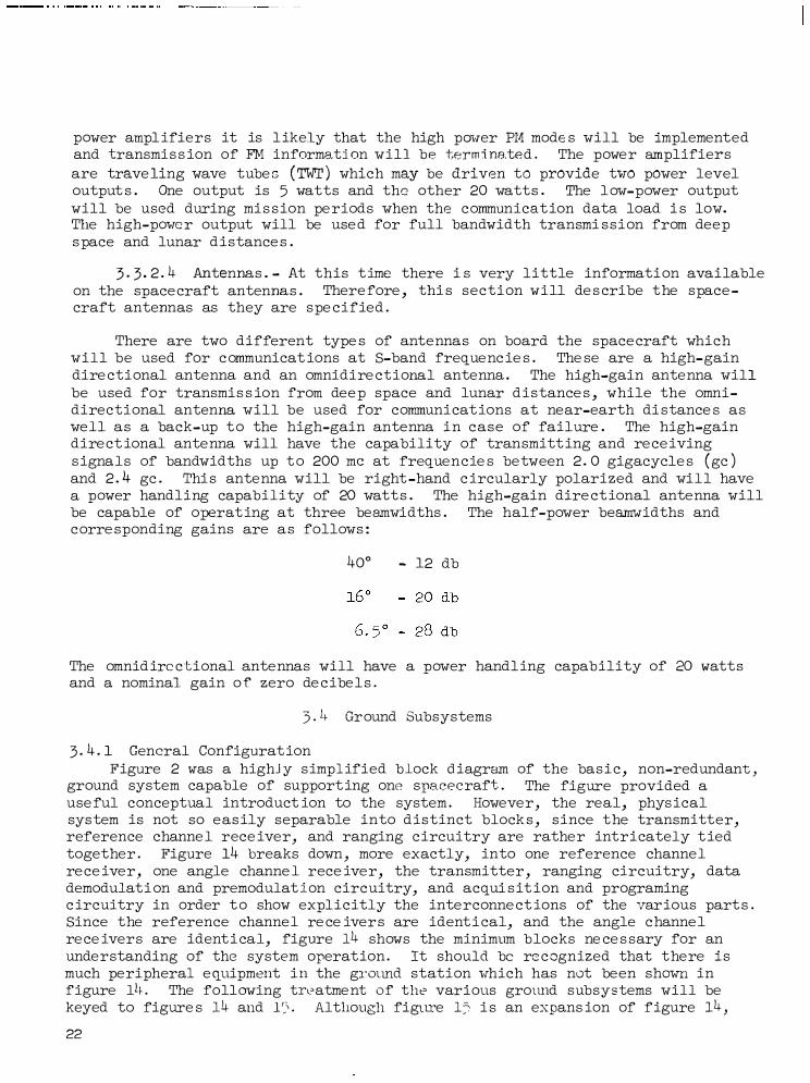
There are two different type s of ante nna s on board the space craft which will be used for c ommunicat ions at S-band freque nc ie s . The se are a high- gain dire ctional antenna and an omnidire ct ional antenna . The high-gain ante nna will be used for transmi s s ion from dee p space and lunar d i s tance s , while the omnidire c t i onal antenna will be used for communi cat ions at near-earth di stance s a s we ll a s a back-up t o the high-gain antenna i n c a s e of failure . The high-gain dire ct ional ante nna will have the capability of transmitt ing and re ce iving s igna l s of bandwidths up t o 200 me at freque n c ie s be tween 2 . 0 gigacycle s ( gc ) and 2 . 4 gc . Thi s ante nna will be right -hand c ircularly polarized and wil l have a power handling capability of 20 watt s . The high-gain dire ct ional ante nna will be capable of operat ing at three beamwidths . The half-power beamwidths and c orre sponding gains are a s follows :
40° - 12 db
The omnid ire c t ional ante nnas will have a power handl ing capab ility of 20 watt s and a nominal gain o f zero de c ibe l s .
3 . L, Gr ound Subsystems
3 . 4 . 1 General Configurat ion Figure 2 was a highJ y s impl ified block d iagram of the ba s i c , non-redundant ,
ground system capable of support ing one spacecraft . The figure provided a use ful conceptual introduct ion to the system . Howeve r , the real, phys ical sys tem is not so e a s ily separable into d i s t inct block s , s ince t he transmitter, reference channe l rece iver, and ranging c ircuitry are rathe r intricately t ied together . Figure 14 breaks down , more exactly, into one reference channe l re ce ive r , one angle channe l rece ive r, the transmitter , ranging circuitry, data demodulat i on and premodulat i on circ uitry, and acqui s it ion and programing c ircuitry in order t o show explic itly the inte rconne ct ions of the var ious part s . Since the reference channe l re ce iver s are ident i cal, and the angle c hanne l re ce ivers are ident i cal, figure 14 shows the minimum b locks ne ce s sary for an unde rstanding of the system operat ion . It should be rc: c ognized that t here i s much pe ripheral e quipment i n the grotmd station 1-rhich has not be en sh0¥.'11 in figure lL� . The following tn,atme nt of the various ground subsystems will be keyed to figure s 14 and 1�' · Although figtU'e 15 i s an expans ion of figure 14 , 22

it is still very much simplified. Most switching, amplification, attenuation, and like circuitry have been deleted. Only that circuitry which contributes to the understanding of the system function has been retained.
3 . 4 . 2 Antennas There are , in the Apollo ground stations , two type s of S-band ground
antennas . One type , used for deep- space communication is an 85-foot parabolic antenna. The other , for near- space communication is a 30-foot parabolic antenna . Since , at this time , the 85- foot antennas for Apollo have not been spe cif ied, this report will cons ider only the 30-foot antenr ta:� .
3 . 4 . 2 . 1 Main near-space antenna. - The main antenna is a 30-foot diameter parabolic reflector with 12-foot focal length, having a Cas segrain feed, supported on an X-Y mount . The antenna is capable of tracking at a maximum rate of 4 degrees per second with maximum acceleration of � degjse c2 down to 2 degrees above the horizon, excepting a lower limit of 10 degree s in the north and south keyhole s , with a pointing accuracy of ±90 seconds of arc . The antenna feed produce s monopulse two-dimensional sum and difference information from which the angle -error drive s ignals for the antenna mount servosystem are derived. The transmitting and re ce iving feeds are circularly polarized, of opposite sense , manually changeable , with a maximum Rxial ratio of 1 . 0 db . The rece iving gain for properly polarized wave s is 4 4 . 0 db above isotropic . The first sidelobe s are specified to be down more than 30 db from the maximum of the main lobe . The main beam-width is approximately 1 . 0 degree .
The antenna and associated drive system are capable of operating in e ight different mode s . The se are manual, slow (manual velocity) , programed, claved (to azimuth-elevat ion source ) , spiral scan, ac�uisition track, automat ic track, ( include s memory track ) , and te st .
3 . 4. 2 . 2 Near- space ac�uisition antenna . - It i s re�uired that an auxiliary antenna be available to aid the main antenna in initial ac�uisition and lock-on of the rece ived s ignal . This ac�uisition antenna will be rigidly mounted on the periphery of the main antenna . Having an approximate diameter of 3 feet, the ac�uisition antenna has a maximum gain of 22 db, a beam-width of roughly 10 degree s , and a tracking accuracy of 0. 5 degree s , total . The ac�uisition feed is of the simultaneous lobing type whose output is circularly polarized with polarization sense that can be set manually.
3 . 4 . 3 Microwave Circuitry As there are two kinds of antennas associated with the deep - space and
near-earth stations , so, also, there are two kinds of microwave circuitry. Figure s 16 and 17 show the circuitry for the deep-space stations and near-earth stations , re spe ctively.
Figure 16 shows the separate sets of antenna feeds for the main antenna and ac�uis it ion antenna, feeding polarization sele ctor switche s . The switche s are arbitrarily shown in the right hand circular polarization (RHCP) pos ition. The main angle s ignals from the polarization switche s are always routed to the main angle channel re ce ivers . Likewi se , the ac�uisition angle s ignals are
23

a lways routed t o the acqui s it ion channe l re ce ive r s . The sum channe l s ignals are routed from the ir re s pe ctive polari zat ion switche s to se parate d iplexe r s . The re ce iver output s of the two diplexers are routed to a switching network which enable s the main sum channel to fee d low noi se amplifier number one and the acqui s i t ion sum channe l t o feed lo�or-no i se ampl i f ie r number two, or vice ver s a . Thi s switching network als o provide s the capabi lity for driving e ithe r low- noise ampl ifier with an RF calibrated noi se s ource .
The outputs of the two low- noi se ampl ifiers are routed to a reference channe l s e le ctor network , whi c h e nable s the main reference channe l re ce iver to be fe d by the ma in- s um channe l s ignal and the acqui s it ion reference channe l re ce iver to be fed by the acqui s ition- sum channe l , or vice versa .
The output o f the ground stat ion transmitter i s routed t o a switching network that enable s it to feed e ither diplexer or a dummy RF load . Thus the transmitted s i gnal may propagate through e ither the ma in or acquis it i on antennas .
Figure 16 de s c r ibe s a stat i on capable of supporting only one s pace craft at a t ime . Figure 1 7 sh01-1s the microwave c ircuitry for a near-earth s tat ion, capable of support ing one spacecraft . The antenna feed polari zation for thi s type station doe s not switch aut omat i cally, b ut must be change d manually. The main angle s ignals are routed directly from the main fee ds to the ir re spe ctive main angle channe l re ce ive r s . The main sum channe l fe ed i s c onne cted to a d iplexer, who se re ce iver output i s routed through a 101-1- no i s e amplifier and dire c t ional couple r to the main reference channe l re ce ive r . It i s seen that the station transmitter s ignal is routed through the diplexer into the main sum channe l feeds . The transmitter doe s not drive the acquis i t i on - sum channe l feeds .
The acqui s it i on angle s ignals are route d from the acqu i s it ion feeds through 101-1-noi se ampl ifiers , dire ctly to the re s pe ct ive acqui s it ion angle channe l re ce ivers . The acqui s i t i on-sum-channel s i gnal i s routed from the acqui s i t ion fee d through a low-noise ampl ifier to a switch. The other input t o the switch is the ma in- s um channe l s ignal, from the d ire ct ional c ouple r . Thi s switch allows the acquis i t i on- refere nce-channe l re ce iver t o be fed by e i the r the acqui sition-s um-channe l s ignal or the ma in-s um- c hanne l s ignal .
3 . 4 . 4 Re ference Channe l Re ce ive r The following de s cr ipt ion i s for PM, or phase- locke d , mode s of operat ion .
When the reference channe l i s used for wideband FM re cept ion , the re ce iver pha s e - locked l oop i s inact ive , and the reference channe l is s imply a manually tuned double - c onvers ion super-heterodyne re ce ive r .
The reference channe l portion of figure 1 5 i s labe led Re ce ive r RF and Automatic Gain Cont:r·ol Circuitry. Thi s port ion i s shown se parate ly in f igure 18 for clarity.
The reference channe l has three bas i c funct ions . One is to translate the incoming comp o s ite s ignal to an intermediate fre que ncy, and po s it ion it in the cente r of the IF pa s s band , us ing a pha se - l ocked channe l , tracking the central
24

carrier component of the signal. The second function is to provide an automatic gain control voltage and carrier acquisit ion signal, activated only by the carrier component , not by noise . The third function is to provide a sinusoidal signal, phase coherent with the rece ive d carrier component , from which e ither one -way or two-way Doppler frequency shift may be determined. There are other operational funct ions, but the se three are the basic conceptual functions .
The princ ipal oscillator for the reference channe l re ceiver is the stable voltage controlled oscillator (VCO) . The twenty megacycle fixed-frequency reference signal is frequency divided by 2 to provide a 10 megacycle reference and also multiplied by 3 to provide a 60 megacycle reference . The 60 and 10 megacycle reference s are used to establish IF frequencie s , fixed at 50 and 10 megacycle s . Additionally, the 10 megacycle reference is used in the RF Doppler detection proce ss in such a way that the frequency stability of the 20 megacycle fixed frequency reference doe s not affect Doppler accuracy.
The incoming composite signal is fed through the S-band amplifiers and pre se lector to the first mixer . The other input to the mixer is a suitably frequency-multiplied version of the 23 . 4-mc VCO signal. The loop locks in such a way that the output of the first mixer has a carrier component at 50 me . Thi s 50-mc component, when heterodyned in the se cond mixer by the 60-mc reference signal, is further frequency translated to 10 me , then introduced to the main carrier phase dete ctor, which is also fed the 10-mc reference signal . It is the error signal produced by this phase detector which cause s the main loop to lock up in the above described manner . It is seen that the outputs of the two mixers are intermediate frequency signals at 50 and 10 me . The se two IF source s feed the re st of the re ception equipment; the 10-mc signal be ing used for the PM mode s and the 50-mc signal for the FM mode s .
3 . 4 . 5 Angle Channel Rece iver The discus sion of the angle channel rece h ·- is keyed to figure 1� .
Figure 19 is included for clarity. The angle channel strongly re semble s the reference channel down through the phase sensitive detector but here it be come s the angle error detector . The angle error dete ctor is basically a phase detector . When the reference channel carrier-tracking loop is locked, the phase of the re ce iver VCO signal is locked to the phase of the carrier component provided by the sum channel of the antenna monopulse feed. The VCO provide s the s ignal which is heterodyned in the first mixer with the carrier component provided by the difference ( or "error" ) channel of the monopulse feed.
If the RF axis of the monopulse antenna feed differs in direction from the Poynting ve ctor (propagation dire ction ) of the rece ived signal, the amplitude and phase of the carrier component in the angle channel is a dire ct measure of this directional difference , or error . The angle error detector provide s a d- e error signal with the proper magnitude and polarity to cause the antenna servo system to align the RF axis of the feed with the arriving signal wave .
3 . 4 . 6 Transmi tter The transmitter in figure s 15 and 20 is that c ircuitry labeled "Transmitter
and Frequency Generating Circuitry. " This subsystem include s a basic Rubidium frequency standard, a frequency synthe sizer phase-locked to the standard, and a
25

master voltage controlled oscillator. The VCO is phase -locked to the frequency synthe sizer and provide s the RF driving s ignal for the transmitter . The synthe sizer provide s the tuning, or frequency changing, capability for the transmitter . The frequency of the synthesizer is changed manually by the operator in discrete frequency steps . Because the frequency changes in steps , the phase-locked VCO is used as the master transmitter oscillator; since the response of the loop to an input frequency step is a continuous smooth transition of the VCO to a new frequency. This smoothne s s of frequency and phase change of the transmitter is neces sary to insure that carrier phase-lock in the space craft rece iver is not broken during ground transmitter tuning. The VCO feeds a multiplier chain which feeds the phase modulator. The other inputs to the modulator are the range code , up-data subcarrier, and up-voice subcarrier . From the modulator, the composite s ignal is routed through suitable multipliers and the power amplifier to the microwave c ircuitry.
3 . 4 . 7 Ranging Circuitry1 The ranging circuitry is made up of those parts of figure 15 labeled
"Rece iver IF Clock Demodulation, Code Correlation Circuitry" , "Re ce iver Coder Clock Transfer Loop and Clock Doppler Detector" , "Re ce iver RF Doppler Dete ctor and Transmitter Clock Generator" , and "Digital Ranging Equipment " . Figure 21, 22, 23, and 24 show the se units separately.
The 10-megacycle IF signal from the reference channel receiver contains , i n its phase , the transponded five -element ranging code which has a square-wave clock signal as one of the components . This 10-megacycle signal is introduced to a balanced heterodyne detector. The other input to the detector is the 10-megacycle reference which has been phase modulated by the signal from the re ce iver code generator (re ce iver coder ) . The code produced by the re ce iver coder can assume any one of seven programable state s . As far as the two code s are concerned, the balanced dete ctor digitally combine s them us ing the Boolean "Module Two Addition" (exclusive or) combining function. The output of the balanced detector depends upon the program state of the rece iver coder and upon the phase of it s output with re spect to the transponded code . Table VI lists the program states of the rece iver coder. It is noticeable that the clock component, cl, doe s not appear in the rece iver coder output . This fact is the key to the operation of the circuitry.
Volume II shows that the output of the balanced detector, for program state P7, with all code components in phase (acquired ) , contains a sinusoidal component at the clock frequency at all time s . Also, for state s Pl or P2, where no code components have been acquired, there is a clock spectral component present in the output of the balanced detector half the time , on the average . During the intermediate program state s , while the transponded code components are be ing acquired or matched in phase , one component at a time , the output of the balanced detector contains a clock s inusoidal component between 25 percent and 100 percent of the time , on the average .
1It is sugge sted that section 4 . 1 . 1 be read before reading this section. Section 4 . 1 . 1 details the basic operation of the pseudo-random-code ranging system. 26

The output of the balanced detector is fed through a bandpass limiter, of 2 kc bandwidth, centered at the nominal clock fre quency, to a phase-locked loop, with a closed-loop noi se bandwidth of the order of a f�w cps . The purpose of this loop is to regenerate or clean-up the rece ived clock signal. The regenerated pure clock, with phase properly adjusted, is fed to a quadrature phase sensitive detector which i s also fed the output of the balanced detector . The purpose of this detector is to produce an indication of the correlat ion between transponded code and rece iver generated code . The correlation indication used is the d-e output of the quadrature phase detector . For state P7, with all re ceiver generated code component s matched in phase to the transponded code component s , the d-e output of the quadrature dete ctor will be some maximum value . Thi s value is taken to indicate 100 percent correlation of the re ce iver generated and transponded code s . For other program state s , where the rece iver generated code components are be ing shifted in phase to match or acquire the transponded components , the re ce ived clock sinusoidal component will be pre sent le ss of the time , on the average , and the effe ctive d-e output of the quadrature detector will be le ss . It is the varying effe ctive d-e output of the dete ctor which is u�ed to indicate varying degrees of correlation between the transponded and rece iver generated code s , and which indicate s the acquisition of a code component .
The pure regenerated clock signal is also fed to the re ce iver coder clock transfer l oop whose function is to supply a frequency doubled version of the clock to the rece iver code generator and a normal clock signal to the clock Doppler detector . � phase-locked loop is required, following the switch shown, so that when the switch is thrown, changing the rece iver coder driving signal from the transmitter clock reference to the rece ived clock, the frequency and phase of the coder driving signal will change smoothly and continuously, rather than in an abrupt step . The clock output of the re ce iver coder clock transfer loop is fed to the clock Doppler dete ctor where it is he terodyned with the transmitter clock reference . The re sulting clock Doppler signal is routed to the range tally. The transmitter clock reference and a doubled version of it are routed to, and drive , the transmitter code generator .
The remaining part of the ranging circuitry to be de scribed is the re ce iver RF Doppler detector and transmitter clock generator, shown in figure s 15 and 23 . It i s required that the transmitter clock signal be phase coherent with the transmitter carrier. Then the re ce iver transponded clock will be phase coherent with the re ce ived carrier and the clock Doppler signal will be phase coherent with the RF Doppler signal . Thi s enable s an increase in range re solution to be obtained by switching from counting the clock Doppler frequency to counting the RF Doppler frequency. The transmitter clock is obtained by coherently frequency shifting the 22-mc master transmitter VCO signal .
The basic princ iple of the RF Doppler detection me chanism is to derive from the transmitted and rece ived carrier components a s ine wave s ignal having a frequency which has a known relationship to the relative velocity of the spacecraft with re spect to the ground station . Figure 25 i s keyed to the following explanation. The notations on the figure are the various normalized signals . In thi s de scription it is important to remember that a frequency multiplier multiplie s phase as we ll as frequency and a mixer subtracts phase ) as well as frequency.
27

There are three bas ic RF generators in the grbund equipment . The se are the master transmitter VCO, rece iver VCO, and the stable reference oscillator . For this discussion, we will represent the radian frequencie s of the se generators as wt' w , and w , re spectively. The explanat ion i s best made by following r o the RF signal from the transmitter VCO and noting its frequency at each step . The transmitter VCO carrier component , cos wtt ' is frequency multiplied by 96
and transmitted to the spacecraft . The space craft rece ive s and transmits this s ignal (with one-way Doppler ) , coherently frequency shifting it by a factor, 240/221 . The s ignal is received at the ground with its frequency multiplied
by the two-way Doppler coefficient , � = l - ?; where C is the velocity of light and V is the space craft radial velocity which is of pos itive sense when directed away from the ground station. The ground rece ived s ignal is mixed first with a s ignal from the rece iver VCO which has been frequency multiplied by 96 . The output of the first mixer is then mixed with a s ignal from the stable reference oscillator which has been frequency multiplied by 3 · An arbitrary phase of ¢ is taken with the reference s ignal . The output of 0 the second mixer is then applied to a phase detector whose other input is the reference signal, frequency divided by 2 . Doppler measurements can only be made when the ground rece iver carrier tracking loop i s locked. For the locked condition the significant output of the phase dete ctor is zero . This allows the representation of wr' the re ce iver VCO frequency, in terms of wt and w0 .
Returning now to the master transmittP.r VCO, the carrier component i s frequency multiplied by 3 and fed t o a mixer . The other input t o the mixer is a frequency multiple of 3 time s the rece iver VCO signal. The output of the first mixer is fed to a second mixer which i s also fed by a signal from the transmitter VCO which has been frequency multiplied by a factor 57/221 . The output of the second mixer is frequency multiplied by 8 and fed to the final Doppler dete ctor . The other input to thi s detector is the reference s ignal which has been effect ively frequency mult iplied by a factor 5/8 .
There are several fine points to be noted in the pre ceding proce s s . First , any possible instability or drift ing in the frequency, w or phase , rt. , of the o 't'o reference oscillator has absolutely no effe ct on the Doppler measurement , since the se effe cts are canceled out in the final Doppler detector . Se condly, the frequency of the final Doppler signal contains the Doppler information in the form of a frequency factor, V/c . It may be shown that for space craft radial ve locities in the order of 10, 000 meters per second, the Doppler dete ctor signal has a frequency of the order of 38 kc .
3 . 4 . 8 Demodulation Circuitry The discuss ion of the data demodulation equipment is keyed to figure s 15
and 26. The two inputs are the 50-mc and 10-mc IF outputs of thP. reference channe l re ce iver s . The ':)O-mc channe l is used during re ception of the FM mode s while the 10-mc channe l is re served for the PM mode s .
28

Except for televis ion and emergency voice , there are two steps in the data demodulation . The first step is the recovery of the individual subcarriers . The second step i s the demodulation of the individual subcarriers . The functional explanation of this circuitry can be st be made by treating the FM and PM mode s separately.
3 . 4 . 8. 1 PM mode s . -
3 . 4 . 8. 1. 1 Voice . The normal ( or recorded ) voice , which i s frequency modulated on a 1 . 25-mc subcarrier and then phase modulated 011 the carrier, enters the data demodulation circuitry via the 10-megacycle JF channel and is introduced to the main PM demodulator. The 10-megacycle input signal is synchronously demodulated by a stable 10-megacycle VCO signal , phase-locked to the incoming carrier component . The voice subcarrier is re covered by the loop and appears at 1 . 25 -mc in the video output of the demodulator .
The re covered voice subcarrier is routed to the paralleled inputs of the voice subcarrier demodulator and PCM telemetry subcarrier demodulator . A bandpas s filter pas se s the voice subcarrier into the normal voice demodulator which is a modulation tracking phase-locked loop. The output of the loop, which is the baseband voice signal is low-pass filtered to pass e ither the reaktime or re corded voice s ignal to the voice output .
3 . 4 . 8 . 1 . 2 Extra-vehicular astronaut (EVA) voice and biomedical telemetry. At the spacecraft the EVA voice and sev8n frequency modulated biomedical subcarriers were summed with the normal spacecraft voice s ignal, frequency modulated on the 1 . 25 -mc subcarrier and then phase modulated on the carrier. This composite s ignal enters the data demodulat ion circuitry via the 10-megacycle IF channel . The modulated subearriers are re covered aloQg with the voice baseband, as in 3 . 4 . 8 . 1 . 1 . The subcarriers are then bandpas s filtered to individual subcarrier demodulators . The seven information channels are routed to the data handling equipment . The EVA voice is low-pass filtered to the voice output .
3 . 4 . 8 . 1 . 3 PCM telemetry. The PCM telemetry (real�ime or recorded) , which was phase-shift keyed on a 1 . 024-mc subcarrier and then phase modulated on the carrier, enters the data demodulation circuitry via the 10-megacycle IF channel and is introduced to the main PM demodulator . The subcarrier is recovered through synchronous detection and appears in the video output at 1 . 024 me . The recovered telemetry subcarrier i s routed to the paralleled inputs to the normal voice demodulator and PCM telemetry demodulator . A bandpass filter pas se s the te lemetry subcarrier in to the telemetry detector . The bi-phase modulated subcarrier enters two parallel channels . The first contains a time s 2 frequency mult iplier . The output of the multiplier i s a stable spectral line or sinusoid at twice the subcarrier frequency, or 2 . 048 me . In multiplying by 2, the biphase modulation is effe ctive ly removed . A phase -locked loop is next used to clean up the 2 . 048-mc signal. The VCO signal, at 2 . 048 me , is then frequency divided by two to obtain a stable reference s ignal at the subcarrier frequency, 1 . 024 me . The reference signal is then routed to the same mixer into which the modulated subcarrieT was introduced . The output of the mixer is the PCM bit stream and noise , which is routed to the bit synchronizer and then to the data handling equipment .
29

3 . 4 . 8 . 1 . 4 Emergency voice . The emergency voice s ignal, which was phase modulated dire ctly on the carrier, enters the data demodulation circuitry through the 10-megacycle IF channel and is introduced to the main PM demodulator . The voice informat ion is recovered through synchronous detection and appears at the output of the main PM demodulator where it is low- pas s filtered and pas sed to the data handling equipment .
3 . 4 . 8. 1 . 5 Emergency key. The emergency key s ignal is a manually keyed 512-kc sine wave , phase modulated on the carrier . Thi s s ignal, which appears as a subcarrier , enters the data demodulation circuitry via the 10-megacycle IF channel and is introduced to the main PM demodulator . The recovered modulation is routed to the emergency key dete ctor which contains both a 512-kc synchronous detector and an envelope detector . The outputs of the se detectors are the emergency key output s .
3 . 4 . 8 . 2 FM mode s . -
3 . 4 . 8. 2 . 1 Voice . The normal ( or recorded ) voice , which is frequency modulated on a 1 . 25-mc subcarrier and then frequency modulated on the carrier, enters the data demodulation circuitry via the 50-megacycle IF channel and is introduced to the main FM demodulator, a modulation tracking loop. This loop has a closed-loop noise bandwidth which is adjustable to optimize re ception of each particular mode . The voice subcarrier is recovered and appears at the output of the modulation tracking loop . The re covered 1. 25 -mc subcarrier is then routed to the input of a voice demodulator where it is treated in the same manner as in the PM mode .
3 . 4 . 8. 2 . 2 Extra-vehicular astronaut (EVA) voice and biomedical telemetry. The biomedical telemetry, summed with normal and EVA voice , enters the data demodulation circuitry via the 50-mc IF as a frequency modulated 1 . 25-mc subcarrier, frequency modulated on the carrier . The composite signal is routed to the main FM demodulator, which recovers the subcarrier . The modulated 1 . 25-mc subcarrier is then routed to a voice demodulator . The recovered subcarriers are then treated as in the pre ceding PM mode .
3 . 4 . 8 . 2 . 3 PCM telemetry. The PCM telemetry, which was phase-shift keyed on a 1 . 024-mc subcarrier and then FM modulated onto the carrier, enters the data demodulation circuitry via the 50-mc IF channel and is introduced to the main FM demodulator . The te lemetry subcarrier, which is re covered by the main FM demodulator, is routed to a PCM telemetry demodulator where it is treated in the same manner as in the PM mode .
3 . 4 . 8 . 2 . 4 Television; The television signal, which was frequency modulated directly on the carrier enters the data demodulation c ircuitry via the 50-mc IF channel and is introduced to the main FM demodulator . The televis ion signal is completely demodulated in this first modulation tracking loop . 'rhe baseband television signal is routed through a low-pass filter to the output .

3 . 4 . 9 Premodulation Circuitry The premodulation c ircuitry, showp in figure s 15 and 20, is fed the base
band voice and up-data s ignals . The voice signal is fre�uency modulated on a 30-kilocycle subcarrier, the up-data on a 70-kilocycle subcarrier . The outputs of the two subcarrier oscillators are then summed and routed to one modulation input of the transmitter phase modulator . Into the other phase modulator input is fed the transmitter ranging code . In the phase modulator, the three up-going information s ignals are effectively summed.
3 . 4 . 10 Ac�uisition and Programing Circuitry The se�uential steps in ac�uisition and ranging are explained in
se ction 4 . 1 . 2 . The c ircuitry associated with the se steps is indicated in a very simple manner in figure s 15 and 24 . Although a complete explanation of the functioning of this circuitry is beyond the scope of this report, the physical operation will be described in simple terms .
The ac�uisition and progr&�ing circuitry monitors portions of the ground system and senses the re sults of various operations . In particular, the d-e output s of the carrier loop �uadrature phase detector and the correlation detector in the range clock rece iver indicate to the ac�uisition and programing circuitry the state of carrier ac�uisition and range code ac�uisition, re spe ctively. Thi s circuitry actually controls the shifting of the rece iver code and up-date s the range tally while shifting the code . It should be noted that antenna drive programing prior to signal ac�uisition is not performed by this circuitry, but by a separate subsystem, described in section 3 . 4. 11.
3 . 4 . 11 Ground System Peripheral E�uipment The previous material has de scribed those ground subsystems which are a
dire ct part of the S-band system. However, there is much peripheral e�uipment re�uired in the operational ground system. This section de scribes briefly some of the peripheral e�uipment used operationally. It disregards items such as signal test unit s , control console s , e�uipment racks, and so forth, which are also regarded as peripheral e�uipment . The e�uipment to be de scribed in this section is as follows :
1 . Antenna position programer
2 . Tracking data proce ssor
3 . Up-Data verification receiver
4 . PCM signal conditioner
The e �uipment listed above has recently been spec ified by Goddard Space Flight Center .
3 . 4 . 11 . 1 Antenna position programer . - The antenna position programer is a special subsystem in the ground station. Its function is to accept spacecraft predictional data and define spacecraft position in the visible sky region of the ground station in �ue stion . The predictional data are transmitted to the remote &ite from the main control center of the S-band ground network.
31

The proce s sor use s a general purpose computer which accepts the predictional data and corre cts these data for errors caused by transmission from the control center to the remote s ite . Then the corre cted data are used to generate antenna drive tapes with words containing time and X, Y, command angle s . These parameters are generated every second or every ten seconds . Additionally, the programer reads the real X and Y angle s from the antenna position encoding subsystem at a rate of 10 per second . The programer compare s the real parameters with the predictional parameters , and, if a difference exists , generates analog voltage s at the rate of 10 per second to correct the antenna control and drive system. Thus , the antenna i s provided with a backup mode (program mode ) should the primary or auto-track mode become inoperable .
3 . 4 . 11 . 2 Tracking data proce s sor . - The tracking data processor is a subsystem which consists of a computer, data storage units , teletype e �uipment , Doppler counters, tape recorders , and a number of gating networks and controls . This subsystem provides time , X and Y angle information, and range and Doppler information in serial form, which i s compatible with two type s of ground communication links; the high speed (2, 000 bits per second ) , and the low speed (60 words per minute ) teletype link . The proce ssor arrange s the above data in a proper format and, at the same time , provide s station identification and other functional information, as re�uired by the network control center . The inputs to the proce ssor are derived from the ranging subsystem, the antenna shaft angle encoding subsystem, the timing subsystem, and the tracking receiver . In addition to the high and low speed data, the proce s sor provides recording of all data on a magnetic tape re corder. Then, in case of a communications failure between remote s ite and the control center, the recorded data can be proce s sed and analyzed at a later time . Provisions are also made for the conversion of the slow speed data from binary to decimal form and for printing of the se data in clear text , paged form.
3 · 4 . 11 . 3 !Jp-data verification receiver . - The up-data verification receiver i s a s ubsystem which i s used to determine whether up-data and voice have been transmitted correctly from the ground station to the space craft . This subsystem consists of a phase locked device for carrier demodulation and 30- and 70-kc discriminators for subcarrier demodulation. ·The input to the re ce iver i s derived from the output . of the power amplifier . Upon demodulation the voice s ignals are monitored for �uality. The demodulated up-data s ignals are compared with those at the output of the digital command system. If an error is detected, correction procedures are immediate ly initiated. In addition to the preceding compari s.on, the transmitted voice and up-data information i s re corded. Thus , a record of the up-link transmitted information exists at all time s .
3 . 4 . 11. 4 PCM s ignal conditioner . - The PCM signal conditioner subsystem is used to test and analyze the performance of the spacecraft-to-ground telemetry channel . This subsystem generates a digital pulse train at the "PCM signal simulator" with bit rate s of 10 to 200 kbs . Thi s signal i s mixed with specific �uantitie s of noise and is capable of driving the up-data subcarrier modulator of the ground system. Additionally, this subsystem is capable of providing pure s ignals (without noise ) to the PCM bit comparator, or a mixed signal and
32

I
noise to the bit synchronizer and s ignal condit ioner, and a clean s ignal ( no noise ) to the bit comparator . The bit synchronizer and s i gnal conditioner accept signal� from e ither the PCM simulator, des cribed above , or the output of the ground telemetry demodulator. The signal conditioner accepts PCM signals under adverse s ignal-to-noi se conditions and reconstruct s the se s ignals to the ir optimum shape with the least noise pos sible . Finally, the bit comparator may receive s ignals from the s ignal simulator and the s ignal conditioner . The se two signals will be made coincident in time . Further, the bit comparator can compare the two s ignals and route an error s ignal to the frequency counter when the inputs in question are not of the same time , phase, or r>olarity.
33

4 . 0 SYSTEM OPERATIONAL TECHNIQUES
4 . 1 Ranging and Spacecraft Ac�uisition
4 . 1 . 1 A Physical Explanation of the Ranging Proce s s
Most of the modulation and information proce ss ing techni�ues employed in the unified system are relatively standard and well documented. The se te chni�ue s include the use of PCM telemetry and analog voice on subcarriers . However, since the JPL pseudo-random code ranging techni�ue employs a system mechanization that is complex, a general phys ical explanation of this proce s s is re�uired. As with most ranging s chemes , this one depends on measuring the round-trip propagation time for some event which is generated by the ranging station. The uni�uene ss of this techni�ue lie s in the nature of the event and the measurement mechanization . Figure s 27 and 28 provide insight into the following explanation.
The event generated by the ground station is a periodic binary waveform. This waveform is composed of a repeating binary seCJ_uence , having a bit length of one microsecond and an unambiguous length of several million bit periods . This length insures that the periodic waveform, or code , does not repeat during the round trip electromagnetic wave propagation time from ground to spacecraft.
The heart of the bas ic system consists of two code generators which prod1 1ce the two range codes described in previous sections of this report , and a range tally, which is a digital machine whose function is to generate range measurement data in response to certain digital inputs . One code generator is driven by a stable clock generator. This generator is' the Transmitter Range Code Generator. The other generator, the Receiver Range Code Generator, is driven by a separate clock generator which is not fixed in rate but , rather, may be phase-locked to a clock signal at its input . Additionally, the receiver generator has the capability to change the phase, or time-delay, of its code in integral bit length steps , in response to digital instructions . Supplementary parts of the bas ic system are a cros s-correlator and indicator to provide a means of knowing when a receiver-generated code is in phase or correlated with the incoming transponded code; and a Doppler fre�uency detector and counter which indicates to the range tally the cumulative phase differences between the transmitter and receiver clock generators.
The range measurement is made as follows : initially the receiver code generator is synchronized in phase to the transmitter code generator and the receiver clock generator is locked to the transmitter clock generator. At this time, the range tally is set to indicate zero range . Meanwhile, the transmitted code is allowed to propagate to the spacecraft and back to the ground. Because of the range and velocity of the spacecraft with respect to the ground station, the code, upon return to the ground, will have a time delay and different clock rate , compared to the transmitted code . Next , the received code generator is freed from synchronization with the transmitter code generator and the receiver clock generator is switched from the transmitter clock generator so that it
34
·----· ·----•- • , • .,,, ' ' "' ' "'-----••••••••-•-••••• •••-- • • •• · ·--···- 1 111 I II I

may acquire and lock to the clock component of the incoming transponded code. At this point, it is helpful to visualize the relationship between the transmitted code and the transponded code as it is received at the ground ( fig. 28) .
Part 1 of figure 28 shows the range code as it is transmitted from the ground station. A certain arbitrary element of the code is identified at time, t Part 2 shows the transponded range code as it i s received at the ground 0 station. At time t1 the same code element identified at the ground transmitter is received on the ground. The time delay, T = t - t is a measure of the I 1 o
Tl spacecraf t- range at a time tR = t1 - 2 since range, R, is given as R = CT 2
( neglecting Earth rotation ) where C is the veloc ity of light and T is the two-way propagation time to the spacecraft. In general, because of the relative movement between ground station and spacecraft, the delay time , T2 , of the code received at time t2 will not be the same as T1 . It should be noticed that the received code does not run at the same rate as the transmitted code ( a Doppler effect ) and is either stretched or compressed in time.
Part 3 of figure 28 shows the receiver-generated code at the start of code acquis ition, slaved in rate and phase of the transmitted code. Parts 3, 4 , and 5 are conceptually correct, but not quite phys ically correct, since the receiver-generated code actually lacks the clock element which is a part of the t �ansmit ted code. In part 4 , at time, t8 , the receiver clock generator is switched away from the transmitter clock generator , to the range clock receiver, and is allowed to acquire the received clock signal. At· some later time , t , c clock acqui sition is complete and the receiver generated code is running at the same rate as , and synchronized on a bit to bit basis with, the re ce ived code . The receiver generated code is not yet matched in phase, or time delay, to the received code .
Starting at time, t , the time at which the receiver generated code s starts separating from the transmitted code in phase, it is required to accumulate, or keep track of, the amount of phase change between the receiver generated and transmitted codes . This is done by detecting the clock Doppler, or difference frequency> between the two clock generators and counting or integrating this frequency. Every time the clock difference frequency makes a zero-cros sing, the receiver generated and transmitted codes have slipped past each other by one bit period. A count of clock Doppler zero crossings , together with an increasing or decreasing sense indication, effectively keeps track of the cumulative phase difference between the transmitted and received generated codes , caused by their running at different rates. This integrated clock Doppler signal is routed to the range tally to keep the continuous range measurement accurate .
Part 5 of the figure shows the result of the final step in acquisition of the coae, that of stepping the receiver code generator in discrete bit steps until it exactly matches in phase, or correlates, with the received code .
35

This correlation is actually obtained by stepping each of the four receiver code components separately, with the range tally being advised of the equiv -alent movement of the entire receiver code . After obtaining correlation of the ent ire code , the continuously up-dated range measurement being displayed by the range tally is correct and has a resolution of about half a bit period or 150 meters . After the acquisition of the transponded code , a step is taken to refine the resolution of the continuous measurement . This is to switch from counting Doppler on the two clock generators to counting Doppler on two RF signals derived phase coherently from the two carriers . Since the clock signals are , themselves , coherept with their respective carriers , the clock Doppler is phase coherent with the RF Doppler. Immediately after tallying a zero cros sing of the clock Doppler, the RF Doppler counter is allowed to commence up-dating the range tally. This increases the resolution of the continuous range measurement to about 1 . 05 meters .
4. 1 . 2 An Explanation of Acquisition
Many signals must be acquired during operation of this system. The following lists the signals and the order in which they must be acquired and gives a brief description of the functioning of the various circuits during acquisition. Many of the acquis ition processes are automated, being run by the acquisition and programming circuitry. This explanation does not depend on a knowledge of the exact method employed to automate the functions . Acquis ition begins with the spacecraft transmitting a carrier which is phase modulated by the voice and PCM telemetry subcarriers .
At the ground station the acquisition antenna is programmed, using previously determined information, to search for the spacecraft signal . This search may consist of a spiral s can motion combined with programmed tracking of a prediction of the spacecraft trajectory.
Combined with the antenna search in angle, the acquisition reference receiver searche s in frequency for the central carrier component of the spacecraft signal. This search is made by sweeping the receiver VCO in frequency. When the VCO frequency is at the proper position relative to the spacecraft carrier component, the acquisition carrier tracking loop will lock. The lock is signi-1"ied by the appearance of a d-e carrier acquisition signal from the RF channel quadrature phase detector.
Once the carrier tracking loop is locked, the antenna angle drive channels become operative. The antenna drive is then s •..ri tched from the programmed search to the acquisition- angle channels . When the acquisition antenna i s sufficiently alined, the main antenYJ.a, which is phys ically tied to the acquis ition ac.tten�'la , acquires the spacecraft signal. The main reference channel VCO is then swept into lock with the carrier co�ponent . This lock activates the main angle channels . The antenna drive is then switched from the acquisition angle channels to the main angle channels .
Next , the carrier tracking loop in the data demodulator is lo�ked up. Then, both the voice and PCM telemetry demodulators are activated. Now, the gro'..lnd trans�itter VCO is swept in frequency antil the spacecraft carrier tracking

loop acquires . Acquisition is signalled at the spacecraft by a d.-c acquis ition s ignal ( the spacecraft coherent automatic gain control voltage ) . The spacecraft in-lock signal and VC'J static phase error are telemetered to the groJ.nd station.
The ground transmitter frequency is then slowly shifted to adjust the telemetered static phase error indication. This adjustment insures that the s ignal received at the spacecraft is properly pos itioned in the spacecraft receiver passband. The voice and up-data subcarriers are rwxt acquired in the spacecraft . W�en a spacecraft FM 1node is being employed, the auxiliary FM ground rece ive is tuned to acquire the FM signal . Then, the main modulation tracking loop in the data demodulator is locked. Be cause of the antenna auto-track mechanization, the PM carrier must be acquired prior to FM acquis ition. At this point all the comnunication channels have been acquired. The final step is to perform the ranging. The five-element ranging code , generated by the transmitter range code generator, is allowed to phase modulate the ground transmitter ana is sent to the spacecraf t. At the spacecraft the code is demodulated and then rem:Jdulated on the down carrier. The code is received on the ground and passes through the main reference channel to the receiver IF clock demodulation and code correlation c ircuitry. Here the clock VCO is swept in frequency and the ranging clock component acquired. Meanwhile, the receiver coder clock transfer loop has been s witched and locked to the transmitter clock signal. The receiver code generator has been matched in phase to the transmitter code generator, and the range tally set to zero. The transfer loop is now s witched and allowed to acquire the received clock signal, sweeping the coder clock transfer loop VCO, if necessary.
Counting and tallying of clock Doppler begins at thi s point . The receiver code generator is now stepped in phase until all four of the code elements are acquired, as s ignalled by the code correlation indication. After acquisition of the complete code , the range tally is switched to count RF Doppler. The transmitter code modulation is then removed. The range tally contiw.les to be up-dated by the RF Doppler, alone . This action completes the acquisition and ranging proceCiure .
4 . 2 L'..llar lVtission ComTiunication Requirements
Detailed chronological corrun'.L7lication requirements for all the Apollo mis sions have not been form'llated at this time, but it is pos sible to outline, in general, the maxim'.111l capabilities required for the 8-band telecorrun'�nication system during the lunar landing mis sion. This description includes the tac it as swnption that the 3-banCi system is the only tracking and communication. system in use during the mis sion. This asswnption will not hold during the launch phase, and may not hold during the earth orbital, reentry, and recovery phases . The requirements will be treated according to mis sion phase.
4. 2 . 1 Prelaunch
Before lal.lnch, from the time the C3M systems are activated and after the astro!lauts have come aboard, the 8-band system will be required to transmit voice ana telemetry and perhaps television to the Mis sion Co:.:1trol Center at
37

Cape Kennedy. It will also be required to check the operation of the system, its elf, before launch.
4. 2. 2 Launch
During the period from the beginning of main booster stage burn, through engine cut-off at insertion into earth orbit , it will be necessary to have S-band tracking, two-way voice, PCM telemetry, up-data, and television. It should be noted that in this and the other phases , the television requirement has the lowest priority. However , given the capability, transmission of television at the indicated times is highly des irable.
4. 2 . 3 Earth Orbit
During the one to four earth orbits before translunar injection , it is required to have tracking from at least two stations on the first orbit and at least one per following orbit . Also required is voice, PCM telemetry, up-data, and television.
4. 2 . 4 Translunar Injection
During the burning of the S- IV-B stage for injection into a translunar trajectory, and depending upon the radio vis ibility of an S-band grotind station, it is desirable to have tracking, voice, and PCM telemetry. During this , as well as the other critical mis sion phases , if communication is not maintained, voice and PCM telemetry will be recorded on board for later playback. However, it is required that ranging, telemetry, voice , �p-data, and recorded data be available before 20 mi nutes after injection.
4. 2. 5 Spacecraft Transposition and LEM Checkout
After injection, during the period when the CSM separates from the remaining portion of the vehicle and removes the LEM, ranging, voice, and telemetry are required and television is des irable. Biomedical telemetry may also be required at this time.
During the period when the LEM systems are being checked out , it will be required to have, simultaneously with both vehicles , voice and telemetry. Required at least sequentially with both vehicles will be up-data, biomedical data, televi sion and tracking.
4. 2. 6 Earth-Lunar Coast
After the LEM checkout period and for the duration of the coast phase , until insertion into lunar orbit, all functions will b e required, from one spacecraft only.
4. 2 . 7 Lunar Orbit
During lunar orbit of both vehicles , before separation of the LEM for desce nt , the LEM systems must again be che cked out . It 1-Till be required to have

I
tracking, voice , PCM telemetry and up-data from both vehicles , simultaneously, and perhaps EVA biomedical data from one vehicle . Additionally, playback of any PCM telemetry and/or voice recorded by the CSM on the back side of the moon may be required.
4. 2 . 8 Lunar Landing, Surface Operations, and Rendezvous
Immediately upon separation of the LEM for the lunar descent, tracking, voice, PCM telemetry, and up-data will be required for both spacecraft s imultaneously. The CSM will continue to require telemetry and voice dump as it orbits the moon. After lunar landing, tracking of the LEM will not be required. However, voice, PCM telemetry, up-data , biomedical data, and television will be required for the LEM during its lunar stay. Simultaneously, the CSM will require all functions except televis ion and biomedical data. For lunar take-off and through rendezvous with the CSM, tracking, voice , and PCM telemetry will be required for both spacecraft simultaneously.
4 . 2 . 9 Moon-Earth Injection and Coast
Requirements for this phase are essentially the same as for the analogous earth-moon phases , with the addition of required tracking of the LEM after separation, to establish its lunar orbit ephemeris .
4 . 2 . 10 Reentry
Tracking, voic e, PCM telemetry, up-data, recorded data playback, and poss ibly television will be required for all non-blackout times . This again depends on the radio visibility of ground stations .
4 . 3 System Operation for a Nominal Lunar Mission
The following is a description of communications occurring during a hypothetical lunar miss ion. It is intended to illustrate the probable sequence of communication events for a nominal mission. The narrative is broken into the logical mis sion phases .
4. 3 . 1 Prelaunch
Before launch, the spacecraft systems are activated. The launch site S-band tracking station antenna is pointed at the spacecraft and acquires the two command module carriers using the spacecraft omniantenna . The �pacecraft then acquires the tracking station carrier. A prelaunch S-band systems checkout operation is then performed. After the preliminary system checkout, the up-link voice and command subcarriers are acquired for operational use . The down-link voice and telemetry subcarriers 8.nd television �ignal arc acQuired in the FM mode . The range code is transmitted and acquireu and range tally of PM carrier Doppler initiated us ing the high povrer PM moue .
4 . 3 . 2 Launch
During booster burn the launch site tracring station continues to Doppler track the spacecraft in the high pover Pl-1 mode anu re ceive te J �metry, vo ice
39
•

·-11111111111111 111111111111111111111
and television in the FM mode. As the spacecraft gains altitude it becomes visible to the go-no-go tracking station down-range. This station ac�uires the spacecraft PM carrier first, then its FM carrier with telemetry, voice and television. At the hand- over time , the launch s ite station ceases transmitting. The go-no-go station observes this event by monitoring the spacecraft telemetered transponder in-lock signal. Rapidly the go-no-go station commences transmitting and causes the spacecraft to ac�uire the new �arrier, voice , and command channels . The go-no-go station then transmits the ranging code , ac�uires it, and �ommences tallying spacecraft PM carrier Doppler.
4. 3 . 3 Earth-Orbit Insertion
For the remainder of powered flight and during insertion, the go-no-go station continues to Doppler track the spacecraft in the high-power PM mode and receive voice, telemetry, and television in the FM mode. When powered flight terminates and after the spacecraft has stabilized, sufficient Doppler track data is accumulated by the go-no-go station to permit the go-no-go decision. After contact with the go-no-go station is lost, spacecraft trans mis sion in the FM mode is terminated. The voice and telemetry channels are switched to the PM mode .
4. 3 . 4 Earth Orbit
For the remainder of time spent in earth orbit , most communication and tracking is performed with the spacecraft in the high-power PM mode, using the Jmniantenna . The only exceptions are if data has been re corded or if television is re�uired. Then the spacecraft FM mode may be initiated.
4. 3 . 5 Translunar Trajectory Injection
Just before the S-IV-B engine is ignited at the beginning of injection, if contact is not be ing maintained with a ground station, voice and PCM telemetry will be routed to the onboard data storage eQuipment. The spacecraft will commence transmitting in the PM mode for ground station ac�uisition. Depending on the geographical location of the injection point, a ground station may not be ac�uired until after injection burn is complete. In any event, the two-way ac�uisition of PM mode carriers , voice, telemetry, up-data, and ranging code will be made in the same manner as before. After ac�uisition, sufficient tracking data is accumulated to give the injection go-no-go decision.
4. 3 . 6 Transposition and LEM Checkout
After the injection go-no-go dec ision, tracking and communications continue in the PM mode, us ing the omniantenna , as the command service module ( CSM ) separates from the remainder of the vehicle to begin transposition and docking with the Lunar Excursion Module ( LEM) . Care must be taken to maintain spacecraft attitude during this maneuver so that the PM links will not be broken. Television and/or data playback may be re�uired at this time. If so, the FM mode will be activated. However, to avoid interruption, real-time PCM telemetry and voice will remain in the PM mode. After docking and transposition is complete , an astronaut enters the LEM and activates the LEM systems . From this
40

I I
point of the mis sion until lunar operations co�nence , the ground-tracking stations must have dual capabilities in all communication functions except angle tracking and ranging. While operational tracking and communications continue using the CSM PM mode , the LEM PM mode is activated and two-way LEM ground acquisition performed. All LEM communications functions are then checked out . During this period the CSM high-gain antenna i s deployed and activated .
4. 3 . 7 Translunar Coast
After the completion of LEM checkout , LEM transmis sion ceases . For the remainder of the flight to the moon, primary communications with the spacecraft continue, using the CSM PM mode with pos sible intermittent FM transmission. If an astronaut leaves the spacecraft , his voice and special biomedical data are relayed through the CSM vo ice channel.
4. 3 . 8 Lunar Orbit
Voice and PCM telemetry will be transmitted in the PM mode during retrofire to insert into lunar orbit. Tracking and ranging will also be performed on the spacecraft , using the PM mode , during retrofire . After insertion into lunar orbit , communication will be accomplished with the CSM in the PM mode . Sufficient tracking data will be accumulated to insure a good orbit around the moon. While the spacecraft is behind the moon, voice and telemetry will be recorded in the data storage equipment . When the spacecraft reappears from behind the moon, two-way s ignal acquisition is made with the CSM in the PM mode. Ranging and tracking is immediately initiated. Real-time voice and telemetry are transmitted through the PM channel. Recorded telemetry and/or voice are transmitted through the FM channel. For the remainuer of· the time that the CSM remains in moon orbit, communications and tracking will continue as before.
4. 3 . 9 Lunar Landing, Surface Operations and Rendezvous
At some time during lunar orbit , two astronauts will transfer · from the CSM to the LEM. The LEM systems will be activated and a checkout procedure initiated. The CSM will be communicating with the earth station in the PM mode. Two-way PM carrier acquisition will be made between LEM and ground. The LEM telemetry, voice, and up-data channels will be activated, and tracking on LEM and CSM, simultaneously, will be initiated. At this point of the mission full dual capability for all communication functions will be required of the earth tracking station s . After LEM systems checkout has been satisfactorily completed and the landing dec ision made, the LEM will s eparate from the CSM and retrofire for descent to the lunar surface. Continuous communication and tracking will be maintained with both spacecraft s imultaneously, in their PM mode s , vi sibility permitting. After a satisfactory LEM descent and landing, tracking of the LEM is not necessary, and voice, telemetry, and television from the LEM may be had in the FM mode. During the stay on the moon ' s surface one astronaut will depart the s pacecraft. His voice and biomedical data will be relayed to earth via the LEM voice channel. Meanwhile, the CSM ground link will be maintained in the PM mode, except for �s s ible recorded data playback in the FM mode. After completion of lunar surface operations the LEM will return to the PM mode for two way acquis ition of carriers , range code, and information channels . The LEM will
41

then boost free of the surface and establish a rendezvous trajectory toward the CSM. Simultaneous tracking and communication with both spacecraft will again be performed in the PM modes .
4. 3 . 10 Earth Trajectory Injection and Coast
After a successful rendezvous, the two LEM astronauts will transfer back to the CSM. The LEM systems will be left on. The CSM will separate from the LEM and boost into an earth transfer trajectory. Communication and tracking with the CSM will be performed in the PM mode with poss ible FM television.
As long as the LEM remains in the ground antenna beam-width of the CSM tracking station, or if a second tracking station is visible, the LEM will be tracked in the PM mode to determine its lunar orbit. After injection into the transfer trajectory, the CSM will coast back toward earth with communications the same as during the outward trip.
4. 3 . 11 Atmospheric Reentry
As the CSM nears the earth, communication will be in the PM mode using the omniantenna with pos sible FM television. Maintenance of communications will depend on the geographical location of the reentry path and the reentry ionization density. Given a visible tracking station, communication in the FM mode will be maintained through landing of the CSM.
42

5 . 0 REFERENCES
1. Baumert , L. , Easterling, M. Golomb, S . W. , and Viterbi, A. : Coding The ory and its Applications to Communications Systems . Technical Report No . 32-67, Jet Propul sion Laboratory, Pasadena, California, March 31, 1961 .
2 . Martin, Benn D. : The Pioneer IV Lunar Probe . A Minimum Power FM/PM System De s ign. Te chnical Report No . 32-215, Jet Propulsion Laboratory, Pasadena, California, March 15 , 1962 .
J

L
44
6. 0 TABLES
TABLE T CODE COMI'ONENT LENGTHS _;_ . -
Code Component Length (bits )
c l 2
X ll
a 31
b 63
c 127
TABLE II. - BIOMEDICAL TELEMETRY CHANNEL DATA
Channel Center Frequency
l 4. 0 kc
2 5 . 4 kc
3 6. 8 kc
4 8. 2 kc
5 9. 6 kc
6 11 . 0 kc
7 12. 4 kc
-, - - � -·-� --- �
Channel Information
Spare
SSA Battery
Suit Pre ssure
Oxygen Pres sure
Suit Temperature
Body Temperature
Impedance Pneumograph

TABLE III. - UP-LINK MODULATION MODES ( PM)
. I Mode Information Transmitted
l-A Range Code Only
l-B Voj_ce Only
l-C Up-Data Only
l-D Range Code + Voice
l-E Range Code + Up-Data
l-F Range Code + Voice + Up-Data
l-G Voice + Up-Data
II

TABLE IV. - DOWNLINK MODULATION MODES
r-----�------------- -
TRANSMITTED INFORMATION -- J REMARKS MODE
PM Channel r -Carrier only I
1-------+--------- r A-1
A-2 Carrier only j A-3 Carrier only
B-1 Range Code
B-2 Range Code
B-3 Range Code & Realtime PCM T/M, Voice , EVA, Biomed.
1
B-4 R�nge Code & Real- j time PCM T /M, Voice, EVA, Biomed.
C-1 Real-time PCM T/M, Voice, EVA, Biomed.
C-2 Real-time PCM T/M, Voice, EVA, Biomed.
�----1---------------
- -Recorded PCM T/M, Recorded Voice
C-3
D-1 Emergency Voice
-
FM Channel - ] - -- - -I
Television & Real-time PCM T/M, Voice, EVA, Biomed.
- -Television & Real-time PCM T/M, Voice, Biomed.
-
EVA,
--- - �
--
Television & Recorded PCM T/M, Recorded Voice
Recorded PCM T /M, Recorded Voice
Real-time PCM T/M, Voice, EVA, Biomed.
l
[
By-pass PM Final Amp.-� J
By-pass PM Final Amp.
By-pass PM Final Amp. 1 By-pas s PM Final Amp.
- - - --
By-pass PM Final Amp._ J
-- - - f-- - -I -·- - - -
-- - - - - - � -
-- - I 1 -D-2 Emergency Voice
E-1 Emergency Key __ 1 ___ __ - - ] _B_y_-_p_a_s_s
__ P_M
__ F_l_·_ n_al Ampj
46
--
-------- --- - --- ---- - --- - --- - - - - -- --- -- - - - - -------------- - - - --- - ------

I
I l r 1 r_ [ I �
I !
TABLE V. - SUBCARRIER FREQUENCIES
Information Channel
Up-link Voice
Up-Data
Down-link Voice -- - �
PCM Telemetry
Recorded PCM Telemetry
Recorded Voice
Biomedical Data
- --
Emergency Key
I Channel Number
I l
- - � - - -- - - -
l
2
3 4
5
6
7
Frequency
30 KC
70 KC --
l . 25 MC
l . 024 MC
l . 024 MC
l . 25 MC
4 . 0 KC
5. 4 KC
6. 8 KC
8. 2 KC
9. 6 KC
ll. O KC
l2. 4 KC
5l2 KC
47

TABLE VI. - RECEIVER CODER PROGRAM STATES
Program States Receiver Coder Output
Pl 0
P2 0
P3 x a
P4 x a
P5 x b
P6 x c
P7 X . [(a . b ) v (b c ) v (a . c )]
48

VOICE
... UP- LINK VOICE , ...,UP- DATA
CSM VOICE ... ... LEM RELAY VOICE .. ..
EVA VOICE a BOS)., .. TREVISION .. .. PCM TELEMETRY_... .. EMERGENCY KEY .. ..
TAPE RECORDER
.. ,j�
PCM TEL E METRY
1 �, I '
· ..... P M RECEIVER ..... .....- ,...-
· FINAL AMPLIFIERS , PREMODULATION
__.. S W I TCHING, ... PM EXCITER .. PROCESSOR A N D
DIPLEXING CIRCUITRY
... Jo. FM EXCITER ..
Figure 1. - The basic spacecraft system
]7 HI- G AIN
N A ANTE N
y "OM N l "
N N A ANTE

MAIN ANTENNA
ACQUISITION ANTENNA MICROWAVE
CIRCUTRY
{ INQUDING DIPLEXER)
50 MC r------:MAI,...,...,....,.N:-:---...,. IF REFERENCE
CHANNEL RECEIVER
MAIN ANGLE CHANNEL
RECEIVERS (2)
ACQUISITION 50 MC I F REFERENCE
CHANNEL 10 MC IF RECEIVER
ACQUISITION ANGLE CHANN
RECEIVERS (2)
TO ANTENNA SERVO SYSTEM
RANGING CIRCUITRY
RANGE CODE
TRANSMITIER 1----------oill--------lpREMOOULAT!ON PM CIRCUITRY
Figure 2. - The Apollo unified S-band ground system
DATA HANDLING
EQUIPMENT
VOICE a UP DATA

MA I N AN TENNA
\7 -
ISITION .ocau ANT ENNA
\V .....____
I
I
MICROWAVE CIRCUITRY
:
....
.... .....
MAIN .... RE FERENCE .. CH ANNEL
RECEIVER
... � MAIN ANGLE
CHANNEL .. RECEIVERS (2)
ACQ U ISITION
50 MC ,........_� FM ., ------,___. ....
IO MC �
�TO ... .. �RVOS ...
50 MC ... ... _.. REFERENCE ... - CHAN N E L 10 M C
RECE IV ER
:: ACQUISITION �TO ANGLE CHANNEL SERVOS � RECEIVERS ( 2 ) �-
. 1 50 MC ____.._ F M .. REFERENCE
� ... CHAN N E L 10 MC. RECEIVER _____J � PM ..
• ..
� REFERENCE 50 MC � CHANNEL ___.
RECE IVER I 0 M C
TRANSM I T T E R r... P M # I
TRAN S M I TTER .. PM # 2
DATA DEMODULATION 1--
CIRCUITRY*!
:: RANGING · � DATA
HAN DLING CIRCUITRY • r EQUIPMEN T r-- ·;--
�\.\.\. ........ ACQUISI TIO N
::: a PROGRAMMI
CIRCUITRY NG
DATA DEMODULATION -
CIRCUITRY#2
RANGING
C I RCUITRY # 2 r-RANGE CODE -
PREMODULATION • CIRCUITRY #1 .. ....
PREMODULATION � RANGE
CODE CIRCUITRY #2 I.. , ....
Figure 3. - The Apollo dual unified S-band ground station

\J1 1\)
PM CARRIER
/:_VOICE SUBCARRIER
I 1 r UP-DATA SUBCARRIER
RANGE CODE ENVELOPE
f o
Figure 4. - The individual up-link

\Jl · VI
PM CARRIER I
fVOICE SUBCARRIER /UP- DATA SUBCARRIER
{ RANGE CODE ENVELOPE
�-++t-H--'--
Figure 5.- The dual up-link
PM CARRIER 2 fVOICE SUBCARRIER /UP- DATA SUBCARRIER

-;; ;;
i !!
PM COHERENT CARRIER
FM NON·COHERENT CARRIER
I RANGE CODE ENVELOPE TV ENVELOPE
T /M SUBCARRIER rr-VOICE SUBCARRIER
r T/M SUBCARRIER
1 r VOICE SUBCARRIER
+ + t + I I I I 1 I : 1 I I I I I I I
(a ) CSM dawn-link
Figure 6. - The dawn-link

I
P M
CO H E R E N T CARR I ER
RANGE CODE
ENVELOPE
F M
NON- COHERENT CA R R l E R
TI M SUBCARRIER 

C SM P M COH E R E NT C AR R IER
CSM PM COHERENT CARRIER
RANGE CODE ENVELOPE
TIM SUBCAR RIER r VOICE SUBCARRIER
RANGE CODE ENVELOPE
FcsM/ ,..
TI M SUBCARRIER {VOICE SUBCARRIER
FCSII/ PII + I . 25 MC
Fcs11;,.11 + I . 024 MC
LEM P M COHER E NT CA R R I E R
RANGE CODE E NV ELO PE
LEM FM N ON COHER E N T CARRIER
TI M SUBCARRI ER r VOICE SUBCARRIER
l L F"""" + I . 25 MC
F LE M / Pll + I . 024 MC
E NVELOPE
TI M SUBCARRIER r VOICE SUBCARRIER
+ I . 25 M C I . 0 24 M C
CSM F M COHERENT CARRIER
CSM FM CO H ERENT CARRIE R
T V ENVELOPE
TI M SUBCARRIER [VOICE SUB CARRIER
FcsM /P'M + I . 25 MC
F CSII/ F ll + I . 024 MC
I I I
T V E NVELDPE
I I I I I I I I I
rTI M SUBCARRI E R
I !VOICE SUBCA RRIER
Cl ll /P'II + I . 25 MC
F Clll/ , .. + I . 0 24 MC
Figure 7. - The dawn-link.��tlosite spectra for LEM and CSM
57

---I 1 111 I I I I III I 1 111111 11111 --� --r-··rnr unl ·- ·· · ·- - - ·· ··· · - --------

\Jl \0
P M COHERENT CARR I E R 4
VOICE E NVELOPE
fo -2. 3 KC/ f'o -300 C P S__/ fo "--f'o+300 CPS
Figure 8. - The emergency voice
-,,

PM COHERENT CAR RIE R
Figure 9· - The emergency key
60
fo + 5 1 2 KC

OH X 2
'-- ·- · -- - ·------
R F IN PUT
l .
PHASE MODULATOR
2
MIXER
1 sT I F
POWER A M PLIFIER
A M PLIFIER
X 2 VARACTOR X 5
M U LTIPLIER
POWER X 5 VARACTER A M P LI F I ER MULTI P L I E R
2 N O I F
X 3
X 3 VARACTER
M U LT I PL I E R
I S O L ATOR
LOAD I S O LATOR
AGC TO PCM
AGC AMPLI FIER
F ILTER
LOOP FILT E R
OUTPUT
F l LT ER
PM MODULATION T RANSPONDER
FM MODULATION FROM T R ANSPONDER
O UTPUT F M F I LT E R
Figure 10. - The
l F I LTER
..,. TO REDUNDANT , TRAN S PONDER R EC E I V E R
T W T P. A .
FI LT E R
·: '
S-band spacecraft subsystem
61
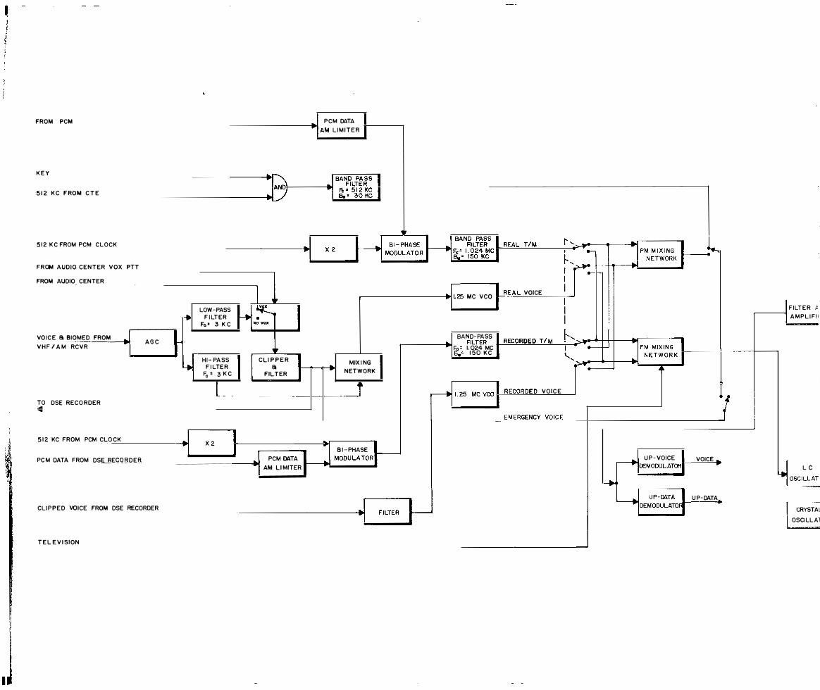
! .1 , ,
:·l,
. l
FROM PCM
K E Y
5 1 2 K C F ROM C T E
5 1 2 K C FROM PCM CLOCK
FROM AUDIO CENTER VOX PTT
FROM AUDIO CENTER
VOI C E a BIOMED FROM V H F / A M RCVR
TO DSE RECO RDER .... ... 5 1 2 KC FROM PCM CLO CK
PC M DATA FROM DS!;_BEQQ B D E B
A G C
CLI P P E D VOICE FROM DSE RECORDER
T E L E V I SION
y
·[
-' PCM DATA ------------------� ... , AM L I M I T E R
LOW-PASS F I LT E R
Fe • 3 K C
H I - PA SS F I LTE R
Fe = 3 K C
L -
X 2 l I
I ,
C L I P P E R a
FILTER
J PCM DATA 'I AM L I MITER
,,
I ....,. ._
.--------------tlii'�I L25 MC VCO �R E A L VOICE
I I I I I
I F I LT E R t r-----tl A M P L I F I I
MIX I NG NETWORK
i
U_ 8 1 - PHASE l� MODULATOR
I BAND- PASS I �����L��·-='���---H-----c�:::-l r----��.1 FILTER • RECORDED TI M . I Fe = 1. 024 MC ! - FM MIX I NG • -------+------t-----, l B.,= 1 5 0 K C , N E TW O R K "
'����-��--.L-�--� �� �-
RECORDED VOIC E
I L______.__J EMERGENC.Y._�V�O�I C�E�---+[ ____________________ _
VOICE _ I L C J U P - VOICE IIDEMODULATOR , OSCILLAT
U P-DATA I CRYST� l OSCILL A1

SUBCARRlER OUTPUT
TO PREMOD PRJCESSOR
PM KlOULATION
FROM FflEMOD PROCESSOR
FM MODULATION
FROM PREMOO PROCESSOR
r - - - - - - - -1 I I RF INPUT
I I I I I I I I I I I I
I I L_ _ _ _ _ _ _ _ _ _ _
I TO PCM I
I I I I I I I I
_ _ j
RF OUTPUT
PM EXCITER _ _ _ _ _ _....
.-- - - - - - - - - - - - -- - - - - - - - - - - - - - - - - - - - - - - - - - - - - - - - - - - -, I
RF OUTPUT I I I I I
FM EXCITER I - - - - - - - - - -- _ _ _ _ _ _ _ _ _ _ _ _ _ _ _ _ _ _ _ _ _j
Figure 12. - The unified S-band transponder

p M
KEY
I KG FRa.l CTE
512 KC FIQ.I PCM CLOCK
FROM AUDIO CENTER VOX- PTT
FROM AUDIO CENTER
VOICE & BIOMED
FROM VHF/AM
RCVR
T R C RDER
REAL T M
REAL VOICE
RECORDED TIM
REODRDED VOICE
-'C"'L"'IP,_,P_,E,D,_,_VO"-"'IC,.E-'FR=O,M,_,_TA,P'-'E'-"R:cEC,O,_,R'-'D"'ER"-------------------1>!�1 FILTER � TELEVISION
FROM S-BAND TRANSPONDER
Figure 11. - The premodulation proces sor
TO XPNOR
TO XPNOR
EMERGENCY VOICE
VOICE
UP-OJ!.TA

S·BAND ANTENNA
- - - - - - - - - - - - l I TRANSPONDER -, ,
--- I 11
I I
RECEIVER I I
JO PREMOD PROCESSOR I F I LTER I I I I
PM INPUT F R OM PREMOD PROCESSOR
I I I I I I I I I I I
RECEIVER
2
PM TRANSMITTER
I
PM TRANSMITTER
2
FM TRANSMITTER
I
TWT POWER
AMPL I F IE R
T W T P O W E R
AMPL I F I E R
FILTER
F I LT E R
I I I I I I I I I l I I I I I I F M I TRANSMITTE I I � - - 2
_ _ _ J L _ __ __ __ _ _ _ _ _ _ _ _ _ _ _j
Figure 13.- The power amplifier

MICROWAVE
CIRCUITRY
ANGLE ERROR TO SERVO SYSTEM
CARRIE R ACQUISITION
CODE CORRELATION
Figure 14. - The basic ground system
1----_. 0THER ACQUISITION
FUNCTIONS
DATA
HANDLING EQUIPMENT
i -

�AIN ANT ENNA
ACQ ANTENNA
, -_ - 1 I I I I
MICROWAVE C I RCU ITRY
a DIPLEXER
I TO ANGLE CHANNEL I i I I I
RECEIVER : R. F. CARRIER PHASE- LOCK a AUTOMATIC GAIN CONTROL CIRCUITRY.
23.8 MC
L - -· - - - - -
I I I I I
I I L....--..a L _ _ _ _ _ r - - - - - --,� I
I I I I
1 2297 MC I fM RECE IVER (ACQUISITION) I .. 1 REFERENCE R.F CHANNEL
L _ _ ·· _ _ _ _j
I L _
L _ _
TO RECEIVE
,.
XMTR COOl
TRANSMITTER, FREQUENCY GENERATING,! a PREMODULATION Cl RCUITRY I
_ _ _ _ _ _ _ _ _ _ _ I 50 MC I P- ATA VO I CE
TO ANTENNA SE .::.....1-----.. SYST

1 1 1 1 1 1
I - ..., .- -1 rl BPF I J BAL !lET L CODE CORRELATION I
- - -- -- - -- - ., z KC I ., 496 KC I I : t F ' s AGc I I I I I I
ILT J vco L I J . 1 ., SHIFT I I ·1 Z3.8 MC I I goo
T I t - RECEIVED CLOCK I
• I I + I T IOMC J BAL OET L 1 I .____! BAL DET L _j BP UM I J fJ so I JLODP FILT I J vco I I .. J , , 10 MC I I , . . 1 I l Z KC I ., 496 KC I T J L 496 KC J : r
.1 I I RECEI V E R : l . F. C LOCK [EMOOt.JLATION r-----------::----4�----
1 I I L AND CODE CORRELATION CIRCUITRY. - . ', � I I II SWITCH I ,.
I � 10 MC REF I I T RCVR '----
-- -- - -- __ _ _) L - - - - - - - - - - - �E _ __ - - _ _ _ _ _ _ _j - --
r- - - - - - -- -�--�-----------4--------�-+--�l�lo��J B P UM I J � so
.- - - - - - - - - - _ _ _ _ _ _ 1 1 tF I 1 L lO Me
I I I : 10 MC REF ,. I RECEIVER ; • I I
R. F. DOPPLER I BIASED I. I MIX I I I DETECTOR AND TRANS- OOPPL CETI I 1 IMITTER CLOCK 1 I I
GENERATOR I I IFREQ MULTI IFREQ MULT I IFREQ w.:r L.._�FI£Q SHIFT I ' I 60 MC X3 I ' X3Z I I X5 r . -� x -t I REF I t 1 I 1 I I I j FREQ MULTl J MIX MIX FREQ MULTl ..JDCPPL DET L!__ IFREQ �Hinl ------4----4>-1�- , X 3 I ., X 8 J "l r I - I l.__x,.....,.._..J I
E I : I I .I FREQ SHIFTI FREQ SHFT I XMTR CLOCK I I _J BA X I _J I l X� I X 2ir I I I : "l L Ml : . , B p LIM
F L- - - - - - - - - - - - - - - - _j I II I BP AMP I .l eAL DET 140 MC I . , 140 MC
--, I i AGC J I I ..
RVO I I AMP I EM 50 MC I 1 __j 50 MC I F T I .Q.t I . I L....- -

CARRIER ACQU IS!J"JON
RECEIVER CLOCK
"2ER CLOCK TRANSFER LOOP JPPLER DETECTOR
DULATOR
-, r--1 1 " I I I I CLOCK DOPPLER
993 KC
496 KC
BIOMEO FILTS
a DE MOO
- - ---, 1---E--to PROGRAMMED I . FUNCTIONS
.....____, I RANGE DATA
ANALDG BIOMEO
PCM T/M
RANGE RATE DATA
� --
I
I I I I I
DIGITAL RANG- I I NG, PROGRAMMING, A ND I ACQUISITIOfi I CIRCUITRY __J
-, I I I I I I I I I I
I OATA SELECTION,! �----�--------��----------�������� PROCE$1NG, I �-��--....!:!!!!::!.!:=��:!:.!...__;_-+.. HANDLING, I
BIOMEO FILTS
a DE MOO
a CONTROL
CONSOLES I I
ANALOG, BIOMEol I I I I I
PCM T/M I I I
T V I ., I r U P- OA�A Lr - � �
.._....,� VOICE J Figure 15 . - The Apollo unified S-band telecommunications
and tracking ground system
67

-
0\ \0
- - - - - - l r -1 MAl N ANTENNA FEED 1 I I I I I I I I I I I L _
r -1 Aca.
I I I
I R H CP X I I L H C P X I RHCP y
I LHCP y
I RHCP SUM
I LHCP SUM
- - - - -
- - - - -
ANTENNA FEED
I RHCP SUM
I LHCP SUM
I RHCP y
I LHCP y
I RHCP X
I
I I '
I
I I I
I
I '
I
: I I I I I
_J
-,
I I
I
I I
I
I L - - - - - _ _l
L. � !.,._
� !...
1
k i 4.
i
TO MAIN X- ANGLE � CHANNEL
DI PLEXER
I
I DIPLEXER
TO ACQ. Y-ANGLE CHANNEL RECEIVER
TO ACQ. X-ANGLE CHANNEL RECEIVER
RECEIVE R
TO MAIN Y- ANGLE CHANNEL RECEIVER
�I LO- NOISE AMPLIFIER
# I
CALIBRATED NOISE
SOURCE
y LO- NOISE AMPLI FIER r :11: 2
.J
L
XMTR RF LOAD
Figure 16. - The deep space station microwave circuitry
� --+TO MAIN REF.
CHANNEL
REFERENCE CHANNEL
SELECTOR
___. --+TO ACO. REF.
CHANNEL
FROM X MTR

MAIN
I X X-ANGLE
CHANNEL
RECEIVER
MAIN
I y _.. Y-AN GLE ..
CHAN NEL
RECEIVER
M AI N
ANTE N N A
� TRANSMITTE R
F E E DS
MAIN
I S U M DIPL E X ER ... LOW NOISE DIRECTION AL .. R EF ERENCE
AMPLIFIER ..
COUPLER ..
CHANNEL REC E I V E R
ACQUISI T ION
I SUM .. LOW NOISE .... REFERENCE
AMPLIFIER .. C HAN NEL
ACQUISITION RECEIVER
ACQUISITION
I X ... LJJW NOISE ... X- ANGLE
AMPLIFIER ..
CHANNEL
A N T E N N A RECEIVER
F EE DS ACQUISITION
I y ... LOW NOISE ... Y-ANGLE
AMPLIFIER -
CHANNEL
RECEIVER
Figure 17. - The near-earth S-band ground station microwave c ircuitry

CARRER ACQUISITION
�
, - - - - - - - - - - - - - - - - - - - - - - - - - - - - - - - - - - - - - - - - - - - - - - - - - --- i iO MC�
I I
� SENSITIVE I
� BANDPASS � VCO I PREAMPLIFIER f---+ MIX MIX fjo� LIMITER,2 KG DETECTOR f---+ LOOP F I LTER t--... 23.4 MC h I
10 MC I I I
60 MC MC 10 MC I
...-------- .---------- 10 � I TO ANGLE CHANNELS
I MULTIPLIER MULTIPLIER FREQUENCY 1 ¢ SHIFTER f4 � SENSITIVE DIVIDER DETECTOR r--I X 96 X 3 2 goo 10 MC I
I � I 23.4 MC I I I I REFERENCE I OSCILLATOR I 20 MC I I I I L _ _ - - - - - - - - - - - - - - - - - - - - - - - - - - - - - - - - - - - - - - - - - - - - - - - - - _ _ .J
Figure 18. - The rece iver RF carrier phase lock
and automatic gain control circuitry
RECEIVER D O PPLER
REFERENCE
O MC � EF

MODULATED CARRIER I N
F ROM REFERENCE CHANNEL
r - - - - - - - - - - - - - - - - - - - - - - - - - -- - - - --, I I I I 1 ..
PREAMPLIFIER ( I I L- -
r--+
RECEIVER ANGLE CHANNEL
60 MC � ,I,
M I X � MIX � BANDPASS � FILTER, 2 KC
Figure 19. - The rece iver angle channel
I I
IO MC I ,lr I
I ANGLE ERROR JTO ANTENNA_.
DETECTOR ISERVO SYSTEM I I
_ _ _ _ .....J

, -1 I I I I I I I I I
4
FR EQUENCY SYNTHESI Z ER
+ ¢ SENS I T I VE
OCTECTOR, 22MC __.
I MC REF.
- - - - - - - - - --,
FREQ U E NCY REFERENCE GEN ERATOR
LOOP FILTER �
RUBID IUM FREQ U E N CY
STANDARD
MASTER VCO
22 MC ��
I I I I I I I I I I
M
CAR
�DULATED
RI ER OUT I AMPLIFIER MULTIPLIER ..__ X 32
MULTI PLIER I +--- ¢ MODULATOR 4---- � X 3
I I I I I L - - -
�l .,
PREMODULATION CIRCUITRY
.n
I I ,, '
I I TRANSMITT� R
REF. ! DOPPLER ..
I I I .4/�
_ _ _ _ _ _ _j - - - - - - - - - - 1 - - - - - -TRANSM IT TER
UP- DATA
VOIC E
Figure 20. - The transmitter, frequency generating and pre-modulation circuitry
CODE

10 MC IF
r- - - - - - - - - - - - - - - - - - - - - - - - - - - - - - - - � I
... ¢ SENSIT IVE I CODE DETECTOR ON lCORRELAll
I I I I ¢ SHIFTER I I ,. I • I
... BALANCED -H· BAN DPASS ___. ¢ SENSITIVE ,......... � I RECEIVED� ... D ETECTOR LIMITER, 2 KC DETECTOR LOOP F I LT E R v co I CLOCK ...
�� I I I I I
¢ MODULATOR 4---- I I I L - - -� �
- - - - - - - - - - - - - - - - - - - - - _ _ _ j - - ·- -RECEIVER CODE
10 MC REF.
Figure 21. - The rece iver IF clock demodulation and code correlation circuitry

r - - - - - - - - - - - - - - - - - - - - - - - - - - - - - - - ., I I RECE IVER CLOCK � ¢ SENSIT IVE I DETECTOR I I t I
CEIVED : RE c LOCK IJI
·�
,,
¢ SENSITIVE
TRAN SMITTER CLOCK
I DETECTOR r---. LOOP FILTER r----. v c o 1---44 DOUBLER X 2 I I I I 1 I 4 DOUBLER X2 I I L _ _ - - - - - - - - - - - - - - - - - - - - - - _ _ _ _ J
Figure 22. - The rece iver coder clock transfer loop and clock Doppler detector
CLOCK �
DOPPLER ...
RECEIVER CLOCK X2 ""
TRANSMITTER.. CLO CK
...
TRANSMITTER � CLOCK X2 ..

RCVR DO PPLER REF.
BIASED R.F. D OPPLER
I MC REF
r - ------ - - - - -- - -- --- - -- - - - - - - - - - l I I I I I I I
I I I I I I
XMTR I DOPPLER
REF I I I I I
I I I I I I I I
MULTIPLIER X 3
L _ _ _ _
I BIASED I DOP PLER M I X
I DETECTO R I ·� I 10 MC R E F. I
�, I MULTIPLIER MULTIPLIER MULTI PLIER FREQUENCY I
X 3 X 32 X 5 SHIFTER I X 5/4
I i I I I I
MIX .. MIX MULTIPLIER - DOPPLER 1
RF DOPPLER x a - DETECTOR
F REQUENCY - SHIFTER . X 57/ 22 1
FR EQUENCY SHIFTER XMTR CLOCK. , X 5/ � I I
-- - - - - - -- - - - - - _ _ _ _ _ _ _ _ ._.,J
Figure 23 . - The re ce iver RF Doppler dete ctor
and transmitter clock generator

r - - - - - - -- - - - - - - - - - - 1 CARRIER! ACQUISITION
i l.j------. i7.w.£0 ----'CO=D=-E ----:,-----�-.. ACQ . ASSY. ..__... PROG. U NIT 1----------;.11-f-"'-.' .. ;.
CORREL l � I I FUNGriONS
I 4� L I
I I I I 1•
I I
R.F. DOPPl....... DATA I RANGE DATA .,
CLOCK I RANGE TA L LY ... HANDLING 1-- I --==-=-=�---:------_.,-.! _... EQU I P M ENT DOPPL. I ... I ..
I I _..
I
RCV R CLOCK
X 2
I R AN GE I I • RAT E I I D� I 1
� RCVR.CODE GEN.� RCVR . I I CODE I I �� I I TRACKING I I DATA I
XMTR I ,r 1 CLOCK I
X MTR CLOCK
X 2
I --:. TRANSMIT TER XMTR . CODE I
L _ _
... _C:E�� - - - - -1- - - - - - - J ,, 1�
Figure 24 . - The digital ranging, programing, and acQuisition circuitry

Figure 25 . - The Doppler detection me chani zation

60 MC REF.
Figure 26.- The re ce iver data demodulator
PCM T/M
EMERGENCY VOICE
KEY
ANALOG BIOMEU
PCM T/ M
T V

CODE SH IFT I N FO
... REC EIVED CLO CK .. cf'HIFT r\� \17
RECE I V E R REC E I VER __., __. CORRELATOR 1.. C O DE 1.. CLOCK ...
r , r'" I GENERATOR GENERATOR I
l I I
�, ORRELATION 't- - - -- _ _ _ _ _ _ _ __j
t � DOPPLER
DETECTOR a � C OUNTER
__. r
\[7 TRANSMITTER TRANSMITTER
... C O D E ... C L O C K .... r'" G E NE R ATOR G E N E R ATO R
Figure 27. - The basic ranging mechanization
R ANGE
DATA RANGE TA LLY t-----e
INTEGRATE
PHASE DI F
'"
D C LOCK
FERENCE

CODE
I. X MTD 0 to
2. R CV D 0 to
RCVR 1 3. G EN
I N I T o t
I 4. I NTER
0
0 to ts
I 5. FINAL
Tl
0 �------------------� to
Figure 28. - The range code acquisition

"The aeronautical and space activities of the United States shall be conducted so as to contribute . . . to the expansion of human knowledge of phenomena in the atmosphere and space. The Administration shall provide for the widest practicable and appropriate dissemination of information concerning its activities and the results thereof."
-NATIONAL AERONAUTICS AND SPACE ACT OF 1958
NASA SCIENTIFIC AND TECHNICAL PUBLICATIONS
TECHNICAL REPORTS: Scientific and technical information considered important, complete, and a lasting contribution to existing knowledge.
TECHNICAL NOTES: Information less broad in scope but nevertheless of importance as a contribution to existing knowledge.
TECHNICAL MEMORANDUMS: I nformation receiving limited distribution because of preliminary data, security classification, or other reasons.
CONTRACTOR REPORTS: Technical information generated in connection with a NASA contract or grant and released under NASA auspices.
TECHNICAL TRANSLATIONS: I nformation published in a foreign language considered to merit NASA distribution in English.
TECHNICAL REPRINTS: I nformation derived from NASA activities and initially published in the form of journal articles.
SPECIAL PUBLICATIONS: Information derived from or of value to NASA activities but not necessarily reporting the results ·of individual NASA-programmed scientific efforts. Publications include conference proceedings, monographs, data compilations, handbooks, sourcebooks, and special bibliographies.
Details on the availability of these publications may be obtainecl lrom:
SCIENTIFIC AND TECHNICAL INFORMATION DIVISION N AT I O N A L A E R O N A U T I CS A N D S PA C E A DM I N I ST R AT I O N
Washington, D.C. 20546