Embed Size (px)
Citation preview

UNICORN TOwER
Install and Operations Manual
“Lancer” is the registered trademark of Lancer © ill by Lancer, all rights reserved.
LANCER
6655 Lancer Blvd.
San Antonio, Texas 78219
To order parts, call
Customer Service: 800-729-1500
Warranty/Technical Support: 800-729-1550
Email: [email protected]
www.lancercorp.com
Manual PN: 28-0883/03
DIGITAL RELEASE ONLY - MAY 2013
FOR QUALIFIED INSTALLER ONLY
PN 85-3151R - VVPN 85-3161R - LFCV

ABOUT THE UNICORN
The Unicorn Tower is designed using the highest quality materials and state-of-the-art technology to provide our customers with consistent quality and a unique drink experience.
TABLE OF CONTENTS
SPECIFICATIONS .................................................................................................................................................................3
wARNINGS/SAFETY/CAUTIONS ........................................................................................................................................4
ELECTRICAL WARNING ...............................................................................................................................................4
WATER NOTICE.............................................................................................................................................................5
ADA STANDARDS FOR ACCESSIBLE DESIGN...........................................................................................................5
DISPENSER INSTALLATION HIGHLIGHTS..................................................................................................................5
PRE-INSTALLATION CHECKLIST.................................................................................................................................6
1. INSTALLATION ..............................................................................................................................................................7
1.1 UNPACKING THE DISPENSER..........................................................................................................................7
1.2 SELECTING A LOCATION FOR THE DISPENSER ...........................................................................................7
1.3 ADA STANDARDS FOR ACCESSIBLE DESIGN................................................................................................7
1.4 INSTALLATION OF THE UNIT .......................................................................................................................7-10
1.5 PLUMBING LINE CONNECTIONS....................................................................................................................11
2. LINE RUN - RECIRCULATING SYSTEM.....................................................................................................................12
3. CONNECTING TO ELECTRICAL POwER..................................................................................................................13
4. CLEANING AND SANITIZING INSTRUCTIONS..........................................................................................................14
4.1 C LEANING & SANITIZING SOLUTIONS ..........................................................................................................14
4.2 DAILY CLEANING..............................................................................................................................................14
4.3 WEEKLY C LEANING & SANITIZING ................................................................................................................15
4.4 CLEANING AND SANITIZING BEVERAGE COMPONENTS - BAG-IN-BOX SYSTEMS ................................16
5. PROGRAMMING OVERVIEw ......................................................................................................................................17
5.1 PROGRAMMING WITH THE VOLUMETRIC HANDHELD PROGRAMMER .................................18-21
5.2 ADJUSTING WATER FLOW AND WATER TO SYRUP RATIO (BRIX) - LFCV ONLY .....................................21
5.3 OPERATION ......................................................................................................................................................21
6. TROUBLESHOOTING .................................................................................................................................................22
7. DISPENSER DISPOSAL..............................................................................................................................................23
8. ILLUSTRATIONS, PARTS LISTINGS, AND wIRING DIAGRAMS.............................................................................23
TOwER, UNICORN, T/C, PC, CC, LFCV - SPARE PARTS LIST LIST
8.1 ELECTRONIC, LFCV SPARE PARTS ...............................................................................................................24
8.2 NOZZLE, LFCV SPARE PARTS .......................................................................................................................25
8.3 VALVE, LFCV SPARE PARTS ...........................................................................................................................26
8.4 WIRING DIAGRAM, LFCV.................................................................................................................................27
TOwER, UNICORN, T/C, PC, CC, VV - SPARE PARTS LIST
8.4 WIRING DIAGRAM, LFCV.................................................................................................................................27
8.5 ELECTRONIC, VV SPARE PARTS....................................................................................................................28
8.6 NOZZLE, VV SPARE PARTS.............................................................................................................................29
8.7 WATER VALVE, VV SPARE PARTS..................................................................................................................30
SYRUP VALVE, VV SPARE PARTS ..................................................................................................................30
8.8 MISC, VV SPARE PARTS..................................................................................................................................31
8.9 WIRING DIAGRAM, VV ......................................................................................................................................32
8.10 COUNTER CUTOUT TEMPLATE ......................................................................................................................33
2
UNICORN TOWER UNITS VV, PN 85-3161R & LFCV, PN 85-3151R
OPERATIONS AND SERVICE MANUAL PN 28-0883/03
3
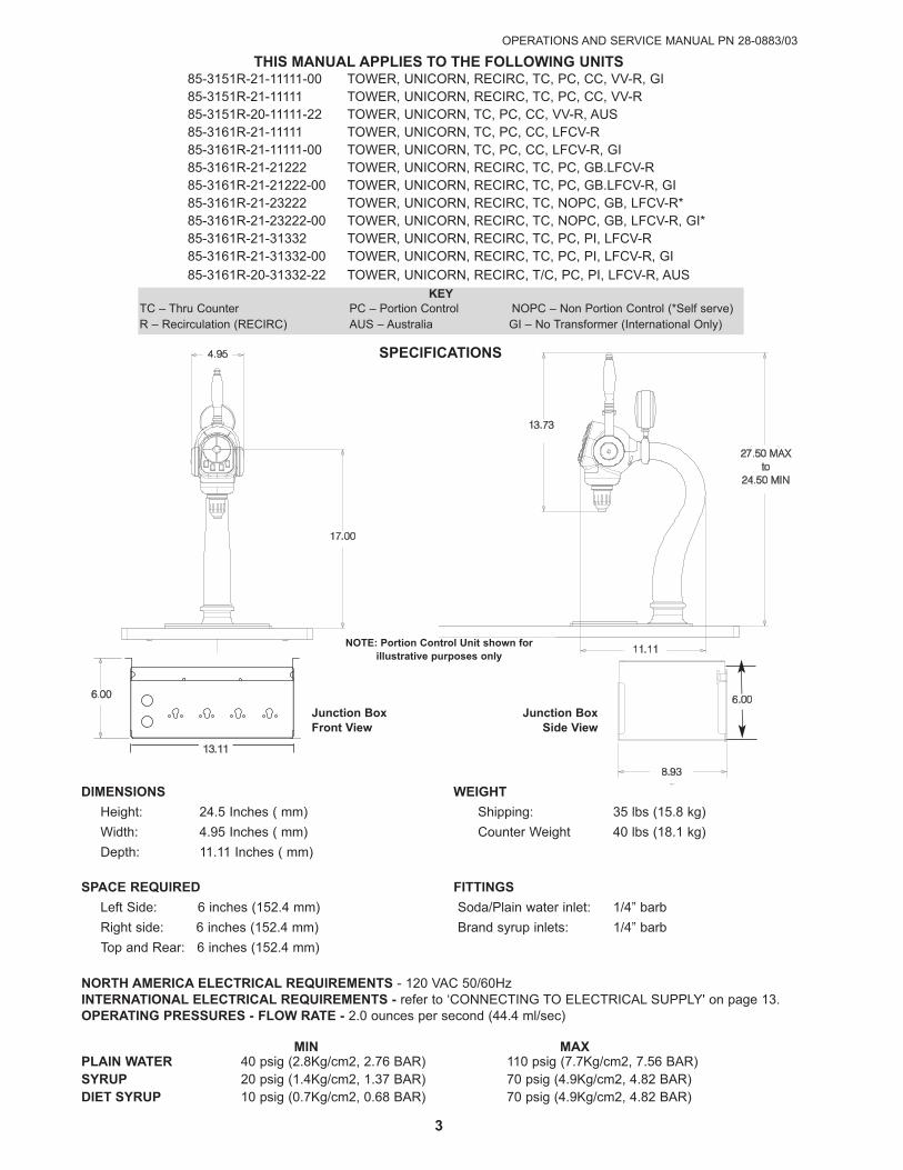
THIS MANUAL APPLIES TO THE FOLLOwING UNITS85-3151R-21-11111-00 TOWER, UNICORN, RECIRC, TC, PC, CC, VV-R, GI85-3151R-21-11111 TOWER, UNICORN, RECIRC, TC, PC, CC, VV-R85-3151R-20-11111-22 TOWER, UNICORN, TC, PC, CC, VV-R, AUS85-3161R-21-11111 TOWER, UNICORN, TC, PC, CC, LFCV-R85-3161R-21-11111-00 TOWER, UNICORN, TC, PC, CC, LFCV-R, GI85-3161R-21-21222 TOWER, UNICORN, RECIRC, TC, PC, GB.LFCV-R85-3161R-21-21222-00 TOWER, UNICORN, RECIRC, TC, PC, GB.LFCV-R, GI85-3161R-21-23222 TOWER, UNICORN, RECIRC, TC, NOPC, GB, LFCV-R*85-3161R-21-23222-00 TOWER, UNICORN, RECIRC, TC, NOPC, GB, LFCV-R, GI*85-3161R-21-31332 TOWER, UNICORN, RECIRC, TC, PC, PI, LFCV-R85-3161R-21-31332-00 TOWER, UNICORN, RECIRC, TC, PC, PI, LFCV-R, GI
85-3161R-20-31332-22 TOWER, UNICORN, RECIRC, T/C, PC, PI, LFCV-R, AUS
DIMENSIONS wEIGHT
Height: 24.5 Inches ( mm) Shipping: 35 lbs (15.8 kg)
Width: 4.95 Inches ( mm) Counter Weight 40 lbs (18.1 kg)
Depth: 11.11 Inches ( mm)
SPACE REQUIRED FITTINGS
Left Side: 6 inches (152.4 mm) Soda/Plain water inlet: 1/4” barb
Right side: 6 inches (152.4 mm) Brand syrup inlets: 1/4” barb
Top and Rear: 6 inches (152.4 mm)
NORTH AMERICA ELECTRICAL REQUIREMENTS - 120 VAC 50/60HzINTERNATIONAL ELECTRICAL REQUIREMENTS - refer to ‘CONNECTING TO ELECTRICAL SUPPLY' on page 13.OPERATING PRESSURES - FLOw RATE - 2.0 ounces per second (44.4 ml/sec)
MIN MAXPLAIN wATER 40 psig (2.8Kg/cm2, 2.76 BAR) 110 psig (7.7Kg/cm2, 7.56 BAR)SYRUP 20 psig (1.4Kg/cm2, 1.37 BAR) 70 psig (4.9Kg/cm2, 4.82 BAR)DIET SYRUP 10 psig (0.7Kg/cm2, 0.68 BAR) 70 psig (4.9Kg/cm2, 4.82 BAR)
KEYTC – Thru Counter PC – Portion Control NOPC – Non Portion Control (*Self serve)R – Recirculation (RECIRC) AUS – Australia GI – No Transformer (International Only)
17.00
4.95
27.50 MAX
to
24.50 MIN
13.73
11.11
6.066
6.000
8.084
7.905
8.084
13.11
Junction BoxFront View
Junction BoxSide View
NOTE: Portion Control Unit shown for illustrative purposes only
8.93
6.0666.000
8.084 7.905 8.084
6.006.00
SPECIFICATIONS

UNICORN TOWER UNITS VV, PN 85-3161R & LFCV, PN 85-3151R
4
! The dispenser is for indoor use only. This unit is not a toy. It should not be used by children or infirm persons with-out supervision. This appliance is not intended for use by persons (including children) with reduced physical, sensory or mental capabilities, or lack of experience and knowledge, unless they have been given supervision orinstruction concerning use of the appliance by a person responsible for their safety. This unit is not designed to dispense dairy products. The min/max ambient operating temperature for the dispenser is 40 to 105 degrees F.
! El dispensador sólo debe usarse en interiores. Esta unidad no es un juguete. No la deben usar niños ni personas discapacitadas sin supervisión. Esta unidad no está destinada al uso por parte de personas (incluso niños)con capacidad física, sensorial o mental reducida, o sin experiencia y conocimientos suficientes, a menos que unapersona responsable de su seguridad les haya dado supervisión o capacitación en el uso de la unidad. Esta unidadno ha sido diseñada para suministrar productos lácteos. La temperatura ambiente operativa mínima/ máxima parael dispensador es de 40 a 105 grados F.
! Le distributeur est destiné à un usage à l'intérieur seulement. Cet appareil n'est pas un jouet. Il ne devrait pas êtreutilisé par des enfants ou des personnes infirmes sans surveillance. Cet appareil n’est pas destiné à un usage pardes personnes (y compris les enfants) ayant des capacités physiques, sensorielles ou mentales réduites, ou man-quant d'expérience et de connaissances, à moins qu'elles obtiennent de la surveillance ou des instructions au sujetde l'utilisation de l'appareil de la part d'une personne chargée de leur sécurité. Cet appareil n'est pas conçu pourdistribuer des produits laitiers. La température de service ambiante minimum/maximum pour le distributeur est de40 à 105 degrés F.
! wARNING/ADVERTENCIA/AVERTISSEMENT
ELECTRICAL wARNING/ADVERTENCIA ELéCTRICA/AVERTISSEMENT éLECTRIQUE F
F Check the dispenser serial number plate for correct electrical requirements of unit. Do not plug into a wall electricaloutlet unless the current shown on the serial number plate agrees with local current available. Follow all local elec-trical codes when making connections. Each dispenser must have a separate electrical circuit. Do not use extensioncords with this unit. Do not ‘gang’ together with other electrical devices on the same outlet. The keyswitch does notdisable the line voltage to the transformer primary. Always disconnect electrical power to the unit to prevent personal injury before attempting any internal maintenance. The resettable breaker switch should not beused as a substitute for unplugging the dispenser from the power source to service the unit. Only qualified personnel should service internal components of electrical control housing. Make sure that all water lines are tightand units are dry before making any electrical connections!
F Verifique la placa con el número de serie del dispensador, donde encontrará los requisitos eléctricos correctos de launidad. No enchufe la unidad en un tomacorriente de pared a menos que la corriente indicada en la placa con elnúmero de serie concuerde con la corriente local disponible. Al hacer las conexiones, respete todos los códigoseléctricos locales. Cada dispensador debe tener un circuito eléctrico independiente. No use extensiones con estaunidad. No la conecte junto con otros dispositivos eléctricos al mismo tomacorriente. El interruptor de llave no cortael voltaje de línea al transformador primario desconecte siempre la alimentación eléctrica a la unidad para evitarlesiones personales antes de tratar de realizar tareas de mantenimiento. El disyuntor de sobrecarga reseteable nose debe usar como sustituto para desenchufar el dispensador de la fuente de alimentación para realizar tareas deservicio de la unidad. El servicio de los componentes internos de la caja de control eléctrico debe confiarse exclusivamente a personal calificado. Asegúrese de que todas las líneas de agua estén ajustadas y las unidadesestén secas antes de hacer conexiones eléctricas.
F Examinez la plaque de numéro de série du distributeur pour connaître les bonnes exigences en matière d’électricité pour l’appareil. Ne le branchez pas à une prise électrique murale à moins que le courant indiqué sur laplaque de numéro de série corresponde au courant local disponible. Respectez tous les codes électriques locauxlorsque vous faites des connexions. Chaque distributrice doit avoir un circuit électrique séparé. N’utilisez pas de cordons prolongateurs avec cet appareil. Ne pas le brancher avec d'autres appareils électriques sur la mêmeprise. L’interrupteur à clé ne coupe pas la tension secteur au transformateur primaire. Débranchez toujours le courant électrique à l'appareil, afin de prévenir des blessures, avant de faire un entretien interne quelconque. Ledisjoncteur réarmable ne devrait pas être utilisé au lieu de débrancher le distributeur de la source d'alimentation enélectricité pour faire de l’entretien/une réparation de l'appareil. Seul le personnel qualifié devrait faire l’entretien/laréparation des composants internes dans le logement des commandes électriques. Assurez-vous que toutes les conduites d’eau sont étanches et que les appareils sont secs avant de faire des connexions électriques!
!
F
OPERATIONS AND SERVICE MANUAL PN 28-0883/03
5
CONTINUED ON NEXT PAGE
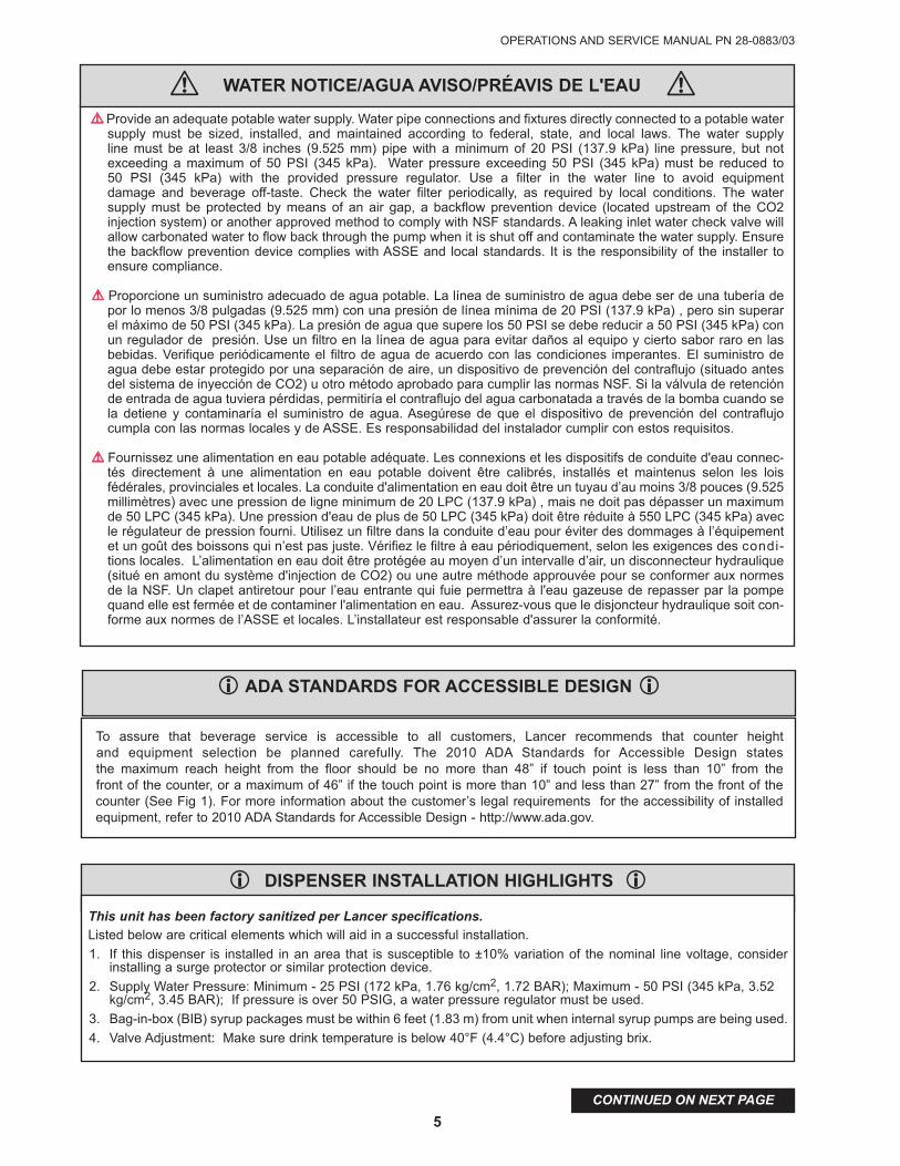
! Provide an adequate potable water supply. Water pipe connections and fixtures directly connected to a potable watersupply must be sized, installed, and maintained according to federal, state, and local laws. The water supply line must be at least 3/8 inches (9.525 mm) pipe with a minimum of 20 PSI (137.9 kPa) line pressure, but not exceeding a maximum of 50 PSI (345 kPa). Water pressure exceeding 50 PSI (345 kPa) must be reduced to 50 PSI (345 kPa) with the provided pressure regulator. Use a filter in the water line to avoid equipment damage and beverage off-taste. Check the water filter periodically, as required by local conditions. The water supply must be protected by means of an air gap, a backflow prevention device (located upstream of the CO2 injection system) or another approved method to comply with NSF standards. A leaking inlet water check valve willallow carbonated water to flow back through the pump when it is shut off and contaminate the water supply. Ensurethe backflow prevention device complies with ASSE and local standards. It is the responsibility of the installer toensure compliance.
! Proporcione un suministro adecuado de agua potable. La línea de suministro de agua debe ser de una tubería depor lo menos 3/8 pulgadas (9.525 mm) con una presión de línea mínima de 20 PSI (137.9 kPa) , pero sin superarel máximo de 50 PSI (345 kPa). La presión de agua que supere los 50 PSI se debe reducir a 50 PSI (345 kPa) conun regulador de presión. Use un filtro en la línea de agua para evitar daños al equipo y cierto sabor raro en lasbebidas. Verifique periódicamente el filtro de agua de acuerdo con las condiciones imperantes. El suministro deagua debe estar protegido por una separación de aire, un dispositivo de prevención del contraflujo (situado antesdel sistema de inyección de CO2) u otro método aprobado para cumplir las normas NSF. Si la válvula de retenciónde entrada de agua tuviera pérdidas, permitiría el contraflujo del agua carbonatada a través de la bomba cuando sela detiene y contaminaría el suministro de agua. Asegúrese de que el dispositivo de prevención del contraflujocumpla con las normas locales y de ASSE. Es responsabilidad del instalador cumplir con estos requisitos.
! Fournissez une alimentation en eau potable adéquate. Les connexions et les dispositifs de conduite d'eau connec-tés directement à une alimentation en eau potable doivent être calibrés, installés et maintenus selon les loisfédérales, provinciales et locales. La conduite d'alimentation en eau doit être un tuyau d’au moins 3/8 pouces (9.525millimètres) avec une pression de ligne minimum de 20 LPC (137.9 kPa) , mais ne doit pas dépasser un maximumde 50 LPC (345 kPa). Une pression d'eau de plus de 50 LPC (345 kPa) doit être réduite à 550 LPC (345 kPa) avecle régulateur de pression fourni. Utilisez un filtre dans la conduite d’eau pour éviter des dommages à l’équipementet un goût des boissons qui n’est pas juste. Vérifiez le filtre à eau périodiquement, selon les exigences des condi-tions locales. L’alimentation en eau doit être protégée au moyen d’un intervalle d’air, un disconnecteur hydraulique(situé en amont du système d'injection de CO2) ou une autre méthode approuvée pour se conformer aux normesde la NSF. Un clapet antiretour pour l’eau entrante qui fuie permettra à l'eau gazeuse de repasser par la pompequand elle est fermée et de contaminer l'alimentation en eau. Assurez-vous que le disjoncteur hydraulique soit con-forme aux normes de l’ASSE et locales. L’installateur est responsable d'assurer la conformité.
! wATER NOTICE/AGUA AVISO/PRéAVIS DE L'EAU
i ADA STANDARDS FOR ACCESSIBLE DESIGN i
To assure that beverage service is accessible to all customers, Lancer recommends that counter height and equipment selection be planned carefully. The 2010 ADA Standards for Accessible Design states the maximum reach height from the floor should be no more than 48” if touch point is less than 10” from the front of the counter, or a maximum of 46” if the touch point is more than 10” and less than 27” from the front of thecounter (See Fig 1). For more information about the customer’s legal requirements for the accessibility of installedequipment, refer to 2010 ADA Standards for Accessible Design - http://www.ada.gov.
i DISPENSER INSTALLATION HIGHLIGHTS i
This unit has been factory sanitized per Lancer specifications.
Listed below are critical elements which will aid in a successful installation.
1. If this dispenser is installed in an area that is susceptible to ±10% variation of the nominal line voltage, considerinstalling a surge protector or similar protection device.
2. Supply Water Pressure: Minimum - 25 PSI (172 kPa, 1.76 kg/cm2, 1.72 BAR); Maximum - 50 PSI (345 kPa, 3.52kg/cm2, 3.45 BAR); If pressure is over 50 PSIG, a water pressure regulator must be used.
3. Bag-in-box (BIB) syrup packages must be within 6 feet (1.83 m) from unit when internal syrup pumps are being used.
4. Valve Adjustment: Make sure drink temperature is below 40°F (4.4°C) before adjusting brix.
!
OPERATIONS AND SERVICE MANUAL PN 28-0255/11
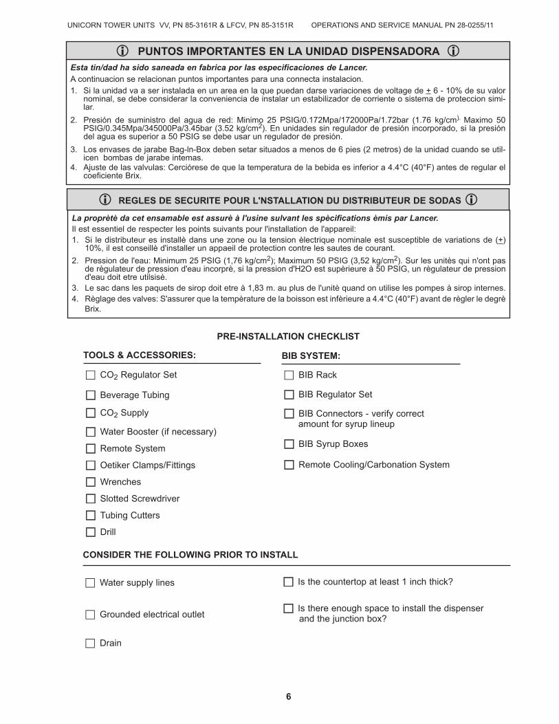
La proprètè da cet ensamable est assurè à I'usine sulvant les spècifications èmis par Lancer.
Il est essentiel de respecter les points suivants pour l'installation de l'appareil:1. Si le distributeur es installè dans une zone ou la tension èlectrique nominale est susceptible de variations de (+)
10%, il est conseillè d'installer un appaeil de protection contre les sautes de courant.
2. Pression de l'eau: Minimum 25 PSIG (1,76 kg/cm2); Maximum 50 PSIG (3,52 kg/cm2). Sur les unitès qui n'ont pasde règulateur de pression d'eau incorprè, si la pression d'H2O est supèrieure à 50 PSIG, un règulateur de pressiond'eau doit etre utilsisè.
3. Le sac dans les paquets de sirop doit etre à 1,83 m. au plus de l'unitè quand on utilise les pompes à sirop internes.4. Règlage des valves: S'assurer que la tempèrature de la boisson est infèrieure a 4.4°C (40°F) avant de règler le degrè
Brix.
i REGLES DE SECURITE POUR L'NSTALLATION DU DISTRIBUTEUR DE SODAS i
Esta tin/dad ha sido saneada en fabrica por las especificaciones de Lancer.
A continuacion se relacionan puntos importantes para una connecta instalacion.
1. Si la unidad va a ser instalada en un area en la que puedan darse variaciones de voltage de + 6 - 10% de su valornominal, se debe considerar la conveniencia de instalar un estabilizador de corriente o sistema de proteccion simi-lar.
2. Presión de suministro del agua de red: Minimo 25 PSIG/0.172Mpa/172000Pa/1.72bar (1.76 kg/cm). Maximo 50PSIG/0.345Mpa/345000Pa/3.45bar (3.52 kg/cm2). En unidades sin regulador de presión incorporado, si la presióndel agua es superior a 50 PSIG se debe usar un regulador de presión.
3. Los envases de jarabe Bag-ln-Box deben setar situados a menos de 6 pies (2 metros) de la unidad cuando se util-icen bombas de jarabe intemas.
4. Ajuste de las valvulas: Cerciórese de que la temperatura de la bebida es inferior a 4.4°C (40°F) antes de regular elcoeficiente Brix.
i PUNTOS IMPORTANTES EN LA UNIDAD DISPENSADORA i
PRE-INSTALLATION CHECKLIST
BIB SYSTEM:
BIB Rack
BIB Regulator Set
BIB Connectors - verify correct amount for syrup lineup
BIB Syrup Boxes
Remote Cooling/Carbonation System
CONSIDER THE FOLLOwING PRIOR TO INSTALL
Water supply lines Is the countertop at least 1 inch thick?
Grounded electrical outlet Is there enough space to install the dispenser
and the junction box?
Drain
TOOLS & ACCESSORIES:
CO2 Regulator Set
Beverage Tubing
CO2 Supply
Water Booster (if necessary)
Remote System
Oetiker Clamps/Fittings
Wrenches
Slotted Screwdriver
Tubing Cutters
Drill
6
UNICORN TOWER UNITS VV, PN 85-3161R & LFCV, PN 85-3151R
OPERATIONS AND SERVICE MANUAL PN 28-0883/03
7
CONTINUED ON NEXT PAGE
1. INSTALLATION
BEFORE GETTING STARTED
Each unit is tested under operating conditions and is thoroughly inspected before shipment. At the time of shipment, the carrier accepts responsibility for the unit. Upon receiving the unit, carefully inspect thecarton for visible damage. If damage exists, have the carrier note the damage on the freight bill and file a claim with carrier.
1.1 UNPACKING THE DISPENSER
A. The Lancer dispenser is shipped in a corrugated shipping carton.
B. Remove dispenser from corrugated shipping carton.
C. Inspect unit and parts for concealed damage. If damage exists, notify delivering carrier and file claimagainst the carrier.
1.2 SELECTING A LOCATION
A. Select a counter location which is near a properly grounded electrical outlet, and a water supply thatmeets the requirements specified in Section 1.6.
B. Unit is designed to be supported by remote chiller system or remote ice cooled system. See themanufacturer’s specifications for installation.
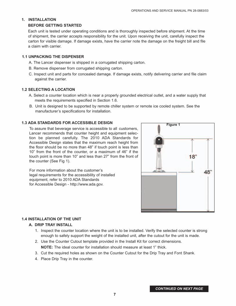
1.3 ADA STANDARDS FOR ACCESSIBLE DESIGN
To assure that beverage service is accessible to all customers,Lancer recommends that counter height and equipment selec-tion be planned carefully. The 2010 ADA Standards forAccessible Design states that the maximum reach height fromthe floor should be no more than 48” if touch point is less than10” from the front of the counter, or a maximum of 46” if thetouch point is more than 10” and less than 27” from the front ofthe counter (See Fig 1).
For more information about the customer’s legal requirements for the accessibility of installed equipment, refer to 2010 ADA Standards for Accessible Design - http://www.ada.gov.
1.4 INSTALLATION OF THE UNIT
A. DRIP TRAY INSTALL
1. Inspect the counter location where the unit is to be installed. Verify the selected counter is strongenough to safely support the weight of the installed unit, after the cutout for the unit is made.
2. Use the Counter Cutout template provided in the Install Kit for correct dimensions.
NOTE: The ideal counter for installation should measure at least 1” thick.
3. Cut the required holes as shown on the Counter Cutout for the Drip Tray and Font Shank.
4. Place Drip Tray in the counter.
Figure 1
UNICORN TOWER UNITS VV, PN 85-3161R & LFCV, PN 85-3151R
8
CONTINUED ON NEXT PAGE
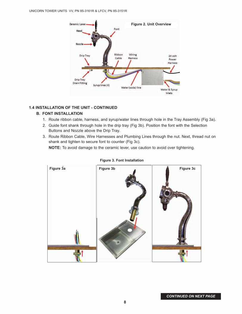
1.4 INSTALLATION OF THE UNIT - CONTINUED
B. FONT INSTALLATION
1. Route ribbon cable, harness, and syrup/water lines through hole in the Tray Assembly (Fig 3a).
2. Guide font shank through hole in the drip tray (Fig 3b). Position the font with the SelectionButtons and Nozzle above the Drip Tray.
3. Route Ribbon Cable, Wire Harnesses and Plumbing Lines through the nut. Next, thread nut onshank and tighten to secure font to counter (Fig 3c).
NOTE: To avoid damage to the ceramic lever, use caution to avoid over tightening.
Figure 2. Unit Overview
Figure 3b
Figure 3. Font Installation
Figure 3a Figure 3c
OPERATIONS AND SERVICE MANUAL PN 28-0883/03
9
CONTINUED ON NEXT PAGE
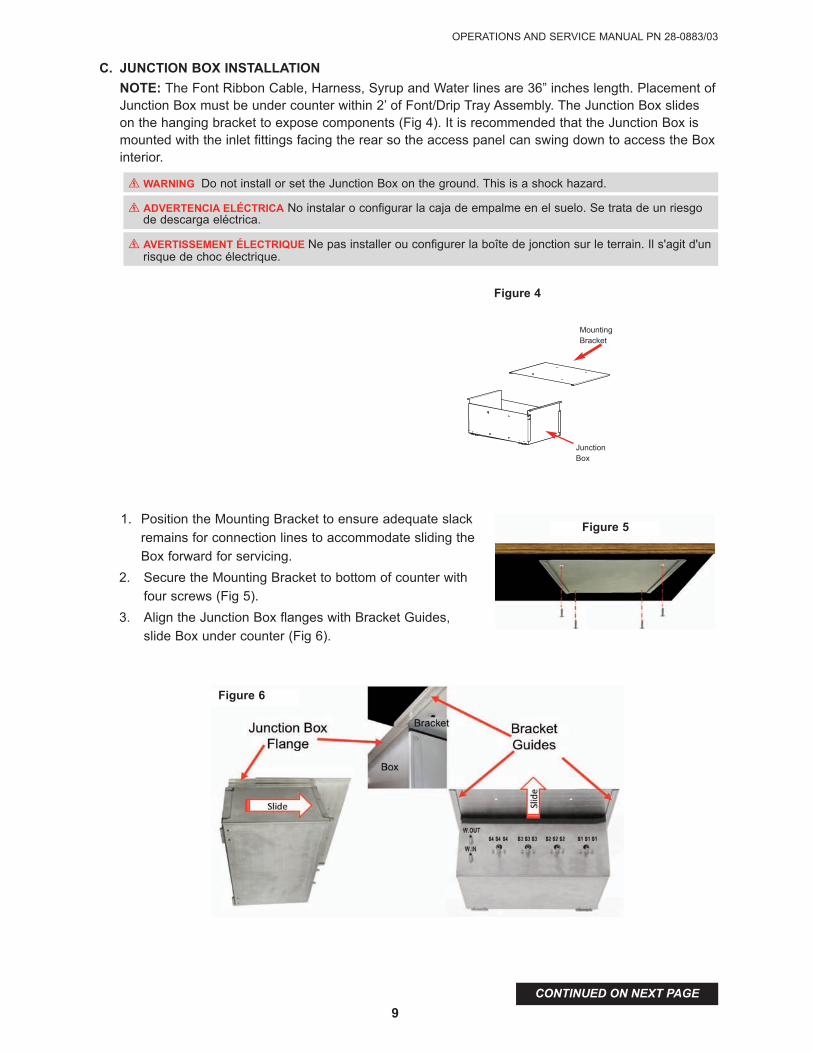
C. JUNCTION BOX INSTALLATION
NOTE: The Font Ribbon Cable, Harness, Syrup and Water lines are 36” inches length. Placement ofJunction Box must be under counter within 2’ of Font/Drip Tray Assembly. The Junction Box slideson the hanging bracket to expose components (Fig 4). It is recommended that the Junction Box ismounted with the inlet fittings facing the rear so the access panel can swing down to access the Boxinterior.
1. Position the Mounting Bracket to ensure adequate slack
remains for connection lines to accommodate sliding the
Box forward for servicing.
2. Secure the Mounting Bracket to bottom of counter with
four screws (Fig 5).
3. Align the Junction Box flanges with Bracket Guides,
slide Box under counter (Fig 6).
Figure 5
F wARNING Do not install or set the Junction Box on the ground. This is a shock hazard.
F ADVERTENCIA ELéCTRICA No instalar o configurar la caja de empalme en el suelo. Se trata de un riesgo de descarga eléctrica.
F AVERTISSEMENT éLECTRIQUE Ne pas installer ou configurer la boîte de jonction sur le terrain. Il s'agit d'un risque de choc électrique.
MountingBracket
Junction Box
Figure 4
Figure 6

UNICORN TOWER UNITS VV, PN 85-3161R & LFCV, PN 85-3151R
10
CONTINUED ON NEXT PAGE
D. JUNCTION BOX wIRING CONNECTIONS1. CONNECT THE FOLLOWING, FOR BOTH Volumetric (VV) AND Lancer Flow Control Valve
(LFVC) MODELS:a. The various Syrup Valve Harnesses from the Unicorn Font to the appropriate connection in
the Junction Box. Refer to the Wiring Diagram in the Junction Box.
b. Connect the Medallion Harness (PN 52-3348) from the Unicorn Font to the appropriate con-nection in the Junction Box.
c. Connect the Ribbon Cable (PN 52-3346) to the Main Board (PN 64-5048) space labeled J8(in the Junction Box).
d. Connect the Power Wire Harness (PN 52-3348) to the Main Board space labeled J1. NOTE: DO NOT CONNECT TO POwER SOURCE AT THIS TIME.
e. For VV Models, continue to Step 3. For LFCV, continue to Step 2.
2. FOR LFCV MODELS ONLY:a. Connect the LFCV Valve Harness (PN 52-3344) to the Selector Board space labeled J3.
b. Continue to SECTION E. JUNCTION BOX PLUMBING LINE CONNECTIONS
3. FOR VV MODELS ONLY:a. Connect the VV KIP Solenoid Harness (PN 52-3359) to the Main Board space labeled J3.
b. Connect the VV Solenoid Harness (PN 52-3360) to the Main Board space labeled J4.
c. Connect the VV Water Harness (PN 52-3361) to the Main Board space labeled J5.
RIBBON CABLE PN 52-3346
POWER WIRE HARNESS PN 52-3348
LFCV VALVE HARNESSPN 52-3344
J8
J1J3
RIBBON CABLE PN 52-3346
POWER WIRE HARNESS PN 52-3348
VV KIP SOLENOIDPN 52-3359
J8
J1J3
VV SOLENOIDPN 52-3360
J4
VV WATERPN 52-3361
J5
RIBBON CABLE PN 52-3346
POWER WIRE HARNESS PN 52-3348
LFCV VALVE HARNESSPN 52-3344
J8
J1J3
RIBBON CABLE PN 52-3346
POWER WIRE HARNESS PN 52-3348
VV KIP SOLENOIDPN 52-3359
J8
J1J3
VV SOLENOIDPN 52-3360
J4
VV WATERPN 52-3361
J5
Figure 7. LFCV
Figure 8. VV

OPERATIONS AND SERVICE MANUAL PN 28-0883/03
11
1.5 PLUMBING LINE CONNECTIONS
A. CONNECTING TO wATER SUPPLY
1. Use a tube cutter to cut tubing. Tubing cut with a saw will result in plastic shavings that could plug
the flow controls in the dispensing valve.
2. Provide an adequate potable water supply. Water pipe connections and fixtures directly connected
to a potable water supply must be sized, installed, and maintained according to federal, state,
and local laws. An adequate potable water supply must be provided. It is recommended that the
supply shut-off is easily accessible. The water supply line must be at least 3/8 inches (9.525 mm)
pipe with a minimum of 20 PSI (137.9 kPa) line pressure, but not exceeding a maximum of 50
PSI (344.74 kPa). Water pressure exceeding 50 PSI (344.74 kPa) must be reduced to 50 PSI
(344.74 kPa) with a pressure regulator. Use filter* in the water line to avoid equipment damage
and beverage off-taste.
* Filter of at least 100 mesh [100 strands per 25mm (one inch)] shall be installed immediatelyupstream of all check valve type backflow preventers used for water supply protection. Thescreen shall be accessible and removable for cleaning or replacement. Check the water filterperiodically, as required by local conditions. The water supply must be protected by means of anair gap, a backflow prevention device (located upstream of the CO2 injection system) or anotherapproved method to comply with NSF standards. Do not connect to a heated (hot) water sourceor a water source supplying soft water. This will cause excessive foaming.
B. JUNCTION BOX PLUMBING LINE CONNECTIONS - FOR LFCV
NOTE: It is recommended that the that plumbing lines to font are routed out rear of Junction Box.
1. Insert the syrup and water lines (from the Unicorn Font) into the appropriate syrup and water out-
lets on the rear of the Junction Box. Refer to Fig 5.
2. There are 2 (two) 1/4” OD Recirculating Water lines, labeled RECIRC. Plug both into the John
Guest Bulkhead Connectors. NOTE: Either RECIRC line can plug into the top.
3. Use the small diameter insulation accordingly to cover all water and syrup tubing.
4. Secure all the fittings in place with the red locking clips.
D. JUNCTION BOX PLUMBING LINE CONNECTIONS - VOLUMETRIC
NOTE: It is recommended that the that plumbing lines to font are routed out rear of Junction Box.
1. Insert the syrup and water lines (from the Unicorn Font) into the appropriate syrup and wateroutlets on the rear of the Junction Box. Refer to Fig 5.
2. Connect the ‘H’ shaped water line to the John Guest Bulkhead Connectors. NOTE: EitherRECIRC line can plug into the top.
3. Secure all the fittings in place with the retainer clips.
! wARNING Check the water filter periodically, as required by local conditions. It is the responsibility of the installer to ensure compliance.
! ADVERTENCIA Verifique periódicamente el filtro de agua de acuerdo con las condiciones imperantes. Es responsabilidad del instalador cumplir con estos requisitos.
! AVERTISSEMENT Vérifiez le filtre à eau périodiquement, selon les exigences des conditions locales. L’installateur est responsible d'assurer la conformité.
S4 S4 S4 S3 S3 S3 S2 S2 S2 S1 S1 S1
Figure 9
UNICORN TOWER UNITS VV, PN 85-3161R & LFCV, PN 85-3151R
12
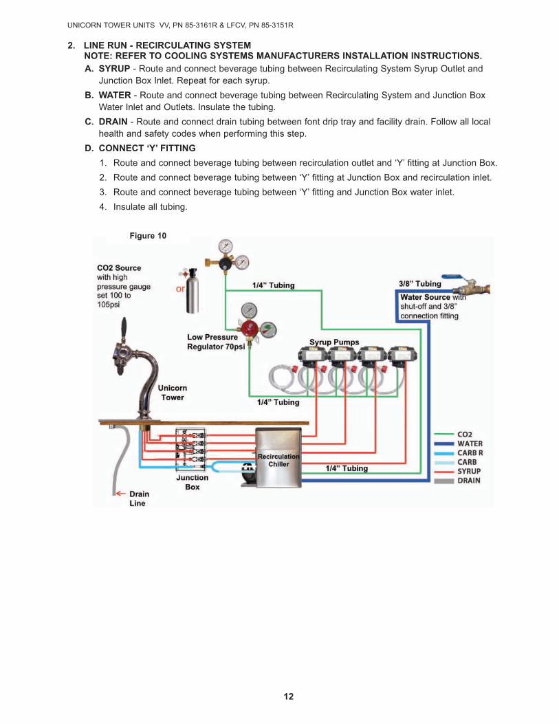
2. LINE RUN - RECIRCULATING SYSTEMNOTE: REFER TO COOLING SYSTEMS MANUFACTURERS INSTALLATION INSTRUCTIONS.A. SYRUP - Route and connect beverage tubing between Recirculating System Syrup Outlet and
Junction Box Inlet. Repeat for each syrup.
B. wATER - Route and connect beverage tubing between Recirculating System and Junction BoxWater Inlet and Outlets. Insulate the tubing.
C. DRAIN - Route and connect drain tubing between font drip tray and facility drain. Follow all localhealth and safety codes when performing this step.
D. CONNECT ‘Y’ FITTING
1. Route and connect beverage tubing between recirculation outlet and ‘Y’ fitting at Junction Box.
2. Route and connect beverage tubing between ‘Y’ fitting at Junction Box and recirculation inlet.
3. Route and connect beverage tubing between ‘Y’ fitting and Junction Box water inlet.
4. Insulate all tubing.
Figure 10
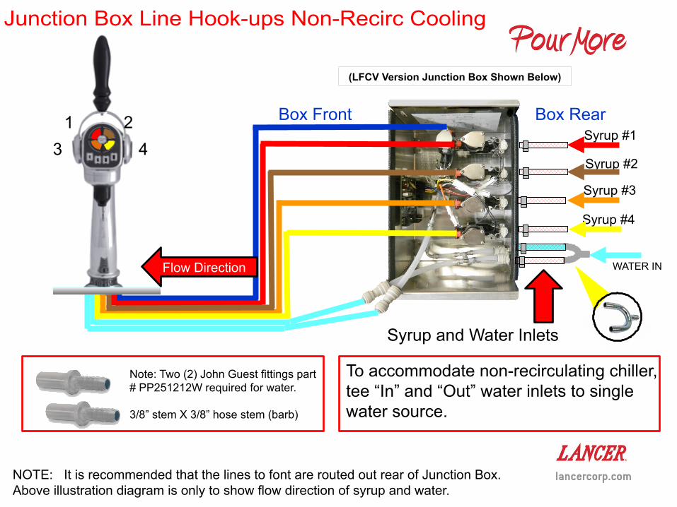
Junction Box Line Hook-ups Non-Recirc Cooling
NOTE: It is recommended that the lines to font are routed out rear of Junction Box.Above illustration diagram is only to show flow direction of syrup and water.
Syrup #1
Syrup #2
Syrup #3
Syrup #4
1
3 4
2
WATER IN
Syrup and Water Inlets
Flow Direction
Box RearBox Front
(LFCV Version Junction Box Shown Below)
Note: Two (2) John Guest fittings part# PP251212W required for water.
3/8” stem X 3/8” hose stem (barb)
To accommodate non-recirculating chiller,tee “In” and “Out” water inlets to singlewater source.

OPERATIONS AND SERVICE MANUAL PN 28-0883/03
13
3. CONNECTING TO ELECTRICAL SUPPLY
NOTE: In addition to the following, adhere to ELECTRICAL wARNINGS AND CAUTIONS, page 4.
NORTH AMERICAN UNITS REQUIREMENTS:Plug the provided transformer (PN 25-0069/01) into the proper wall socket.
INTERNATIONAL TRANSFORMER (NOT PROVIDED) REQUIREMENTS:Rated 50 VA or higher, primary voltage as required, and a Secondary Voltage 24VAC. Overcurrent andsurge protection is recommended. Connector wires for the transformer are included in the unit.
F wARNING Check the dispenser serial number plate for correct electrical requirements of unit. Do not plug into a wallelectrical outlet unless the current shown on the serial number plate agrees with local current available. This unit mustbe properly electrically grounded to avoid possible fatal electrical shock or serious injury to the operator. The power cordhas a three-prong grounded plug. If a three-hole grounded electrical outlet is not available, use an approved method toground the unit. Follow all local electrical codes when making connections. Each power supply must have a separateelectrical circuit. Do not use extension cords. Do not “gang” together with other eletrical devices on the same outlet. Thekeyswitch does not disable the line voltage to the transformer primary. ALWAYS disconnect power to the dispenser beforeattempting any internal maintenance. Only qualified personnel should service internal components of electrical controlhousing. Make sure that all water lines are tight and units are dry before making any electrical connections!
! ADVERTENCIA ELéCTRICA Verifique la placa con el número de serie del dispensador, donde encontrará los requi-sitos eléctricos correctos de la unidad. No enchufe la unidad en un tomacorriente de pared a menos que la corriente indi-cada en la placa con el número de serie concuerde con la corriente local disponible. Esta unidad debe estar debidamenteconectado a tierra para evitar posibles choques eléctricos mortales o lesiones graves al operador. Le bloc d’alimentationdoit être mis à la terre électriquement correctement pour éviter des blessures graves ou une décharge électriquemortelle. Le cordon d’alimentation a une fiche à trois branches mise à la terre. Si aucune prise de courant électrique àtrois trous n'est disponible, utilisez une méthode approuvée pour mettre l’unité à la terre. Al hacer las conexiones, respetetodos los códigos eléctricos locales. Cada dispensador debe tener un circuito eléctrico independiente. No use exten-siones con esta unidad. No la conecte junto con otros dispositivos eléctricos al mismo tomacorriente. El interruptor dellave no corta el voltaje de línea al transformador primario. Desconecte siempre la alimentación eléctrica a la unidad paraevitar lesiones personales antes de tratar de realizar tareas de mantenimiento. El servicio de los componentes internosde la caja de control eléctrico debe confiarse exclusivamente a personal calificado. Asegúrese de que todas las líneasde agua estén ajustadas y las unidades estén secas antes de hacer conexiones eléctricas.
! AVERTISSEMENT éLECTRIQUE Examinez la plaque de numéro de série du distributeur pour connaître les bonnesexigences en matière d’électricité pour l’appareil. Ne le branchez pas à une prise électrique murale à moins que lecourant indiqué sur la plaque de numéro de série corresponde au courant local disponible. L'unité doit être mise à la terreélectriquement pour éviter une décharge électrique mortelle ou des blessures graves possibles à l'opérateur. Le bloc d’al-imentation doit être mis à la terre électriquement correctement pour éviter des blessures graves ou une décharge élec-trique mortelle. Le cordon d’alimentation a une fiche à trois branches mise à la terre. Si aucune prise de courant élec-trique à trois trous n'est disponible, utilisez une méthode approuvée pour mettre l’unité à la terre. Respectez tous lescodes électriques locaux lorsque vous faites des connexions. Chaque source d’alimentation doit avoir un circuit élec-trique séparé. N’utilisez pas de cordons prolongateurs. Ne branchez pas plusieurs appareils électriques à la même prisede courant. L’interrupteur à clé ne coupe pas la tension secteur au transformateur primaire. Déconnectez TOUJOURSl’alimentation en électricité à la distributrice avant de faire de l’entretien interne. Seul le personnel qualifié devrait fairel’entretien/la réparation des composants internes dans le logement des commandes électriques. Assurez-vous quetoutes les conduites d’eau sont étanches et que les appareils sont secs avant de faire des connexions électriques!
UNICORN TOWER UNITS VV, PN 85-3161R & LFCV, PN 85-3151R
14
CONTINUED ON NEXT PAGE
4. CLEANING AND SANITIZING INSTRUCTIONSA. The cleaning and sanitizing procedures provided herein pertain to the Lancer equipment identified by
this manual. If other equipment is being cleaned, follow the guidelines established by the manufac-turer for that equipment.
B. Lancer equipment (new or reconditioned) is shipped from the factory cleaned and sanitized in accor-dance with NSF guidelines. The equipment must be cleaned and sanitized after installation is com-plete. The operator of the equipment must provide continuous maintenance as required by this man-ual and state and local health department guidelines to ensure proper operation and sanitationrequirements are maintained.
C. Cleaning and sanitizing should be accomplished only by trained personnel. Sanitary gloves are to beused during cleaning and sanitizing operations. Applicable safety precautions must be observed.Instruction warnings on the product being used must be followed.
D. Other Required Supplies: 1) Clean cloth towels, 2) bucket, 3) extra nozzle, 4) sanitary gloves and 5)Small brush PN 22-0017 from installation kit.
4.1 CLEANING AND SANITIZING SOLUTIONS
CLEANING SOLUTION: Mix a mild, non-abrasive detergent (e.g. Sodium Laureth Sulfate, dish soap) with clean, potable water at a temperature of 90 to 110°F (32 to 43°C). The mixture ratio is one ounce of cleaner to two gallons of water. Prepare a minimum of five gallons of cleaning solution. Do not use abrasive cleaners or solvents because they can cause permanent damage to the unit. Ensure rinsing is thorough, using clean, potable water at a temperature of 90 to 110 degrees F. Extended lengths of product lines may require additional cleaning solution.
SANITIZING SOLUTION: Prepare sanitizing solutions in accordance with the manufacturer’s written recommendations and safety guidelines. The solution must provide 50 to 100 parts per million (PPM) chlorine (e.g. Sodium Hypochlorite or bleach). A minimum of five gallons of sanitizing solution should be prepared. Any sanitizing solution may be used as long as it is prepared in accordance with themanufacturer’s written recommendations and safety guidelines, and provides 50 to 100 parts per million (PPM) chlorine.
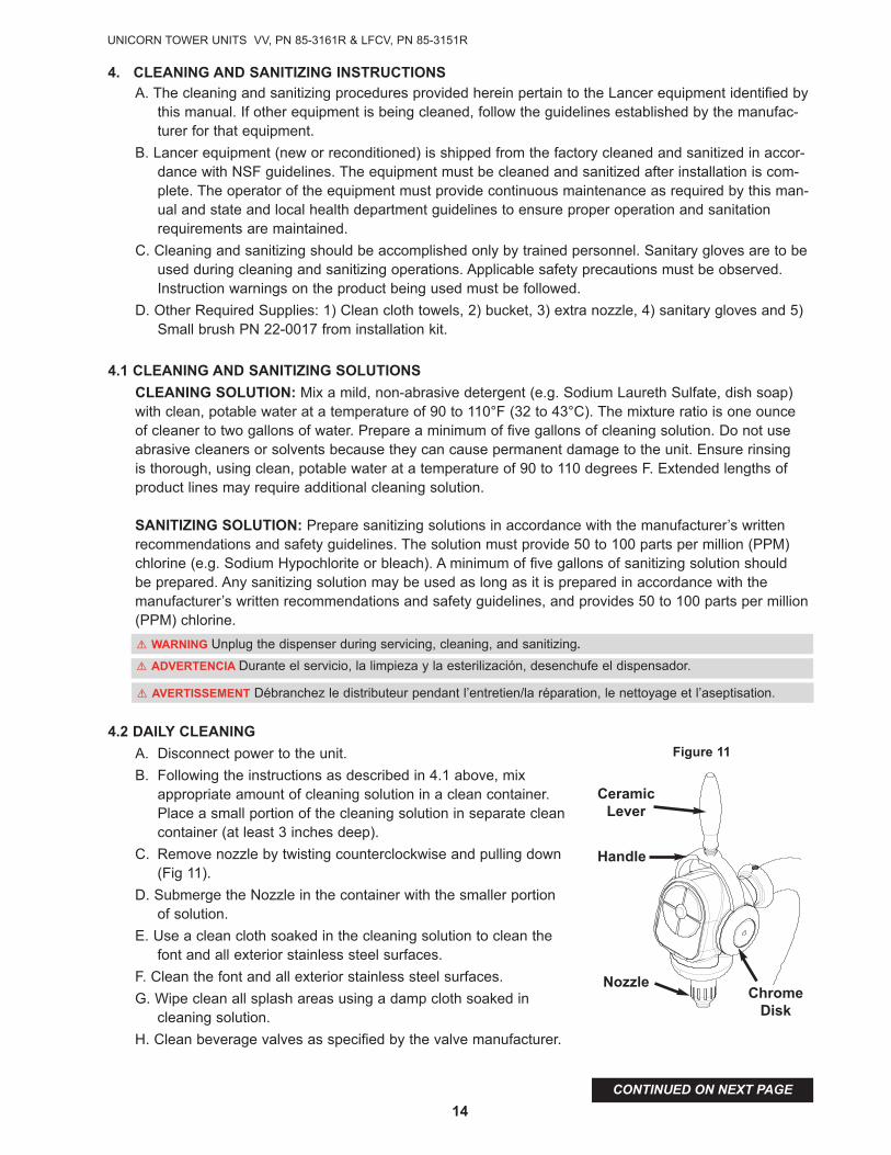
4.2 DAILY CLEANING
A. Disconnect power to the unit.
B. Following the instructions as described in 4.1 above, mix appropriate amount of cleaning solution in a clean container.Place a small portion of the cleaning solution in separate cleancontainer (at least 3 inches deep).
C. Remove nozzle by twisting counterclockwise and pulling down (Fig 11).
D. Submerge the Nozzle in the container with the smaller portion of solution.
E. Use a clean cloth soaked in the cleaning solution to clean the font and all exterior stainless steel surfaces.
F. Clean the font and all exterior stainless steel surfaces.
G. Wipe clean all splash areas using a damp cloth soaked in cleaning solution.
H. Clean beverage valves as specified by the valve manufacturer.
! wARNING Unplug the dispenser during servicing, cleaning, and sanitizing.
! AVERTISSEMENT Débranchez le distributeur pendant l’entretien/la réparation, le nettoyage et l’aseptisation.
! ADVERTENCIA Durante el servicio, la limpieza y la esterilización, desenchufe el dispensador.
CeramicLever
Handle
NozzleChrome
Disk
Figure 11
OPERATIONS AND SERVICE MANUAL PN 28-0883/03
15
CONTINUED ON NEXT PAGE
4.3 wEEKLY CLEANING AND SANITIZING
A. Disconnect power to the unit.
B. Following the instructions as described in 4.1 above, mix appropriate amount of sanitizing solution in a clean container. Place small portionof the cleaning solution in a separate clean container (no less than 3 inches deep).
C. To remove the Nozzle (Fig 11) from the dispenser, grasp the Nozzleand pull downward.
D. Submerge the Nozzle in the container with the smaller portion of solution.
E. Place the Nozzle in the set aside portion of solution.
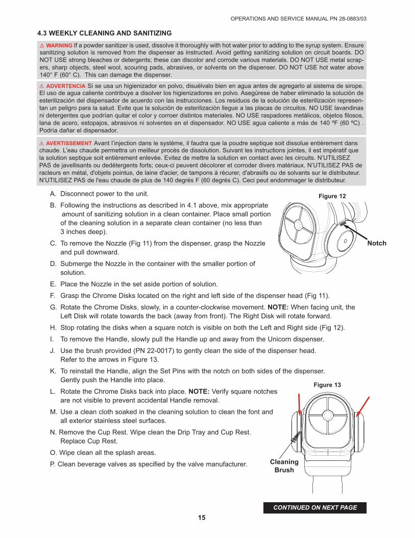
F. Grasp the Chrome Disks located on the right and left side of the dispenser head (Fig 11).
G. Rotate the Chrome Disks, slowly, in a counter-clockwise movement. NOTE: When facing unit, theLeft Disk will rotate towards the back (away from front). The Right Disk will rotate forward.
H. Stop rotating the disks when a square notch is visible on both the Left and Right side (Fig 12).
I. To remove the Handle, slowly pull the Handle up and away from the Unicorn dispenser.
J. Use the brush provided (PN 22-0017) to gently clean the side of the dispenser head. Refer to the arrows in Figure 13.
K. To reinstall the Handle, align the Set Pins with the notch on both sides of the dispenser. Gently push the Handle into place.
L. Rotate the Chrome Disks back into place. NOTE: Verify square notchesare not visible to prevent accidental Handle removal.
M. Use a clean cloth soaked in the cleaning solution to clean the font andall exterior stainless steel surfaces.
N. Remove the Cup Rest. Wipe clean the Drip Tray and Cup Rest. Replace Cup Rest.
O. Wipe clean all the splash areas.
P. Clean beverage valves as specified by the valve manufacturer.
! wARNING If a powder sanitizer is used, dissolve it thoroughly with hot water prior to adding to the syrup system. Ensuresanitizing solution is removed from the dispenser as instructed. Avoid getting sanitizing solution on circuit boards. DONOT USE strong bleaches or detergents; these can discolor and corrode various materials. DO NOT USE metal scrap-ers, sharp objects, steel wool, scouring pads, abrasives, or solvents on the dispenser. DO NOT USE hot water above140° F (60° C). This can damage the dispenser.
! AVERTISSEMENT Avant l’injection dans le système, il faudra que la poudre septique soit dissolue entièrement danschaude. L’eau chaude permettra un meilleur procès de dissolution. Suivant les instructions jointes, il est impératif quela solution septique soit entièrement enlevée. Evitez de mettre la solution en contact avec les circuits. N’UTILISEZPAS de javellisants ou dedétergents forts; ceux-ci peuvent décolorer et corroder divers matériaux. N’UTILISEZ PAS deracleurs en métal, d'objets pointus, de laine d'acier, de tampons à récurer, d'abrasifs ou de solvants sur le distributeur.N’UTILISEZ PAS de l'eau chaude de plus de 140 degrés F (60 degrés C). Ceci peut endommager le distributeur.
! ADVERTENCIA Si se usa un higienizador en polvo, disuélvalo bien en agua antes de agregarlo al sistema de sirope.El uso de agua caliente contribuye a disolver los higienizadores en polvo. Asegúrese de haber eliminado la solución deesterilización del dispensador de acuerdo con las instrucciones. Los residuos de la solución de esterilización represen-tan un peligro para la salud. Evite que la solución de esterilización llegue a las placas de circuitos. NO USE lavandinasni detergentes que podrían quitar el color y corroer distintos materiales. NO USE raspadores metálicos, objetos filosos,lana de acero, estopajos, abrasivos ni solventes en el dispensador. NO USE agua caliente a más de 140 ºF (60 ºC) .Podría dañar el dispensador.
Notch
Figure 12
CleaningBrush
Figure 13
UNICORN TOWER UNITS VV, PN 85-3161R & LFCV, PN 85-3151R
16
4.4 CLEANING AND SANITIZING BEVERAGE COMPONENTS - BAG IN BOX SYSTEM
NOTE: Extended lengths of product lines may require more time for flushing and rinsing lines than described below.
A. Disconnect the syrup quick disconnect coupling from the syrup packages and connect the couplingto a bag valve removed from an empty Bag-in-Box (BIB) package.
B. Place the syrup inlet line in a clean container filled with clean, potable, room temperature water.
C. Activate valve until water is dispensed. Flush and rinse line and fittings for a minimum of 60 secondsto remove all traces of residual product.
D. Following the instructions as described in 4.1 above, mix appropriate amount of cleaning solution ina clean container. Place syrup inlet line in container filled with cleaning solution.
E. Activate valve and draw cleaning solution through lines for a minimum of 60 seconds. This willensure line is flushed and filled with cleaning solution. Allow line to stand for at least 30 minutes.
F. Place syrup inlet line in a clean container filled with clean, potable, water at a temperature of 90° to110°F.
G. Activate valve to flush and rinse line and fittings for a minimum of 60 seconds to remove all traces ofcleaning solution. Taste dispensed product to ensure there is no off-taste. If off-taste is found, addi-tional flushing of syrup system may be required.
H. Following the instructions as described in 4.1 above, mix appropriate amount of sanitizing solution ina clean container. Place syrup inlet line in container filled with sanitizing solution.
I. Activate valve and draw sanitizing solution through line for a minimum of 60 seconds. This willensure line is flushed and filled with sanitizing solution. Allow line to stand for at least 30 minutes.
J. Remove bag valve from quick disconnect coupling and reconnect syrup inlet line to syrup package.Ready unit for operation.
K. Draw drinks to refill lines and to flush the chlorine sanitizing solution from the dispenser.
L. Test dispenser in normal manner for proper operation. Taste dispensed product to ensure there is nooff-taste. If off-taste is found, additional flushing of syrup system may be required.
M. Repeat cleaning, rinsing, and sanitizing procedures for each valve and each circuit.
! wARNING Following sanitization, rinse with end-use product until there is no aftertaste. Do not use a fresh water rinse. This is an NSF requirement. Residual sanitizing solution left in the system creates a health hazard.
! AVERTISSEMENT Défense de rincer l’outil à l’eau fraiche immédiatement après un traitement septique. En cas de après-goût, ne purger avec le produit final une exigence NSF.
! ADVERTENCIA Después de la esterilización, enjuague con el producto final hasta eliminar el sabor que queda. No enjuague con agua fresca. Ésta es una exigencia de NSF. Si queda solución de esterilización en el sistema, genera un peligro para la salud.
OPERATIONS AND SERVICE MANUAL PN 28-0883/03
17
CONTINUED ON NEXT PAGE
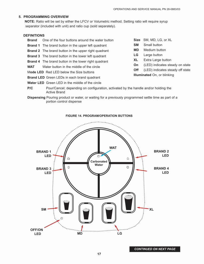
5. PROGRAMMING OVERVIEwNOTE: Ratio will be set by either the LFCV or Volumetric method. Setting ratio will require syrup
separator (included with unit) and ratio cup (sold separately).
DEFINITIONSBrand One of the four buttons around the water button
Brand 1 The brand button in the upper left quadrant
Brand 2 The brand button in the upper right quadrant
Brand 3 The brand button in the lower left quadrant
Brand 4 The brand button in the lower right quadrant
wAT Water button in the middle of the circle
Mode LED Red LED below the Size buttons
Brand LED Green LEDs in each brand quadrant
water LED Green LED in the middle of the circle
P/C Pour/Cancel; depending on configuration, activated by the handle and/or holding the Active Brand
Dispensing Pouring product or water, or waiting for a previously programmed settle time as part of a portion control dispense
Carbonatedwater
Size SM, MD, LG, or XL
SM Small button
MD Medium button
LG Large button
XL Extra Large button
On (LED) indicates steady on state
Off (LED) indicates steady off state
Illuminated On, or blinking
SM XL
MD LGOFF/ON
LED
BRAND 1LED
BRAND 3LED
wATBRAND 2
LED
BRAND 4LED
FIGURE 14. PROGRAM/OPERATION BUTTONS
UNICORN TOWER UNITS VV, PN 85-3161R & LFCV, PN 85-3151R
18
CONTINUED ON NEXT PAGE
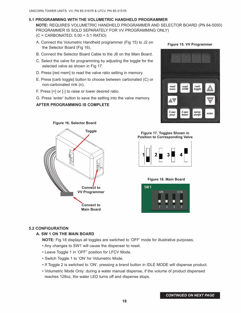
Figure 16. Selector Board
Toggle
Connect to VV Programmer
Connect to Main Board
5.1 PROGRAMMING wITH THE VOLUMETRIC HANDHELD PROGRAMMERNOTE: REqUIRES VOLUMETRIC HANDHELD PROGRAMMER AND SELECTOR BOARD (PN 64-5050)PROGRAMMER IS SOLD SEPARATELY FOR VV PROGRAMMING ONLY)(C = CARBONATED; 5.00 = 5:1 RATIO)
A. Connect the Volumetric Handheld programmer (Fig 15) to J2 onthe Selector Board (Fig 16).
B. Connect the Selector Board Cable to the J8 on the Main Board.
C. Select the valve for programming by adjusting the toggle for theselected valve as shown in Fig 17.
D. Press [red mem] to read the valve ratio setting in memory.
E. Press [carb toggle] button to choose between carbonated (C) ornon-carbonated rink (n).
F. Press [+] or [-] to raise or lower desired ratio.
G. Press ‘enter’ button to save the setting into the valve memory.
AFTER PROGRAMMING IS COMPLETE
5.2 CONFIGURATIONA. Sw 1 ON THE MAIN BOARD
NOTE: Fig 18 displays all toggles are switched to ‘OFF’ mode for illustrative purposes.
• Any changes to SW1 will cause the dispenser to reset.
• Leave Toggle 1 in ‘OFF” position for LFCV Mode.
• Switch Toggle 1 to ‘ON’ for Volumetric Mode.
• If Toggle 2 is switched to ‘ON’, pressing a brand button in IDLE MODE will dispense product.
• Volumetric Mode Only: during a water manual dispense, if the volume of product dispensed
reaches 128oz, the water LED turns off and dispense stops.
Figure 17. Toggles Shown inPosition to Corresponding Valve
Figure 18. Main Board
Figure 15. VV Programmer

OPERATIONS AND SERVICE MANUAL PN 28-0883/03
19
CONTINUED ON NEXT PAGE
B. IDLE MODE
This is the normal operating mode of the dispenser. At the start of IDLE MODE, the modeLED is turned off.
• Active brand is indicated by the illuminated LEDs. (ON - active/ OFF - not active). Only one brand can be Active at a time.
C. IDLE MODE - TO DEACTIVATE A BRAND, wHILE THE UNIT IS NOT DISPENSINGPRODUCT
• Select an inactive Brand. This will activate the selected Brand and deactivate the formerlyActive Brand.
- To deactivate an Active Brand without selecting an inactive Brand, press the ActiveBrand button for less than .35 seconds.
• The Active brand automatically deactivates If the last recognized button press and thelast dispense were both at least 10 (ten) seconds prior.
D. MANUAL BRAND DISPENSE
1. Select the desired brand if it is inactive.
2. Pull and hold the handle to pour.
NOTE: Depending on configuration, press and hold any brand while idle to pour.
E. wATER DISPENSE
• To dispense water manually, Press and hold WAT button. Water LED will illuminate (Active Brands automatically deactivate).
If P/C or WAT buttons are not pressed, the Water LED will turn off and dispense stops.
• During a manual dispense, if 60 (sixty) seconds elapse, the Water LED turns off and the dispense stops.
F. PORTION CONTROL DISPENSE
A. Select a Brand.
B. Select a Size
NOTE: Depending on configuration, pressing and holding the active brand will stop a portion dispense in progress
G. PURGE MODE
NOTE: Purge mode allows independent purging of water or syrup without shutting off theback block.
• If unit is in IDLE MODE without a selected Active Brand, AND has not dispensed sinceunit was powered on, the PURGE MODE can be accessed by pressing and holding bothBrand 1 and Brand 4 buttons for 5 seconds.
• During in Purge Mode, the Mode LED blinks at low duty cycle.
• Press and hold WAT, to dispense water
• Press and hold a Brand, to dispense syrup only
• The unit will default to IDLE MODE automatically, if:
- the unit is NOT dispensing AND the last button press AND last dispense were both at least 60 (sixty) seconds prior.
- the unit is NOT dispensing AND the handle is pulled.
UNICORN TOWER UNITS VV, PN 85-3161R & LFCV, PN 85-3151R
20
CONTINUED ON NEXT PAGE
H. TIMED POUR MODE
NOTE: Timed pour mode assists flow rate calibration
If unit is in IDLE MODE without an Active Brand, and has not dispensed product since the unit waspowered on, the TIMED POUR MODE can be accessed by pressing and holding both Brand 1 andBrand 2 buttons for 5 seconds.
• During TIMED POUR MODE, the Mode LED blinks rapidly.
• Press WAT, to dispense water.
• Press a Brand, to dispense syrup only for the selected Brand
• Dispense ends after 8 seconds
• The unit will default to IDLE MODE automatically, if:
- the unit is NOT dispensing AND the last button press AND last dispense were both at least
60 (sixty) seconds prior, unit will return to IDLE MODE.
- the unit is NOT dispensing AND the handle is pulled, the unit returns to IDLE MODE.
I. PROGRAM MODE
NOTE: The unit supports separate portions with up to 1 topoff for each brand
If the unit has an Active Brand, the PROGRAM MODE can be accessed by pressing and holding boththe SM and XL buttons.
• During PROGRAM MODE, the Mode LED blinks.
• During PROGRAM MODE and its sub-modes, all dispenses use the Active Brand.
• During PROGRAM MODE and its sub-modes, the information stored for a Size is ONLY for theActive Brand
1. Put desired amount of ice in cup, place cup under valve
2. Press and hold the size to be programmed until cup fills to desired portion
3. If a topoff is not recessary, return to Step 1 with a different size or press the Active Brand to exitportion program mode and save the programmed sizes.
4. Wait for foam to settle, then press and hold the size again to top off.
5. Return to Step 1 with a different size or press the Active Brand to exit portion program mode
• The unit will default to IDLE MODE automatically, if the unit is NOT dispensing AND the last
button press AND last dispense
J. CALIBRATED CUP PORTION CONTROL PROGRAMMING FOR VOLUMETRIC MODE
NOTE: In this mode, the unit adds the volume from each programming step to the total drink size.
When the portion is dispensed from idle mode, the entire drink is dispensed without pauses.
If unit has an Active Brand selected, Calibrated Cup Portion Control Programming MODE can be
accessed by pressing and holding both the SM and LG buttons.
• During Calibrated Cup Portion Control Programming MODE, the Mode LED blinks.
• During Calibrated Cup Portion Control Programming MODE and its sub-modes, all dispenses usethe Active Brand.
• During Calibrated Cup Portion Control Programming MODE and its sub-modes, the informationstored for a Size is ONLY for the Active Brand.
1. Place volume cup under nozzle.
2. Press appropriate size and fill volume cup to a point just short of the calibration mark on the vol-ume cup. LED will turn ‘on’ while programming an individual cup size
3. Allow foam to settle, jog size button until liquid reaches the calibration mark on the volume cup.

OPERATIONS AND SERVICE MANUAL PN 28-0883/03
21
J. CALIBRATED CUP PORTION CONTROL PROGRAMMING FOR VOLUMETRIC MODE - CONT.
4. Press the Active Brand to end programming the selected cup size. LED will return to blinking.
5. Start at step 1 with a different size or press the Active Brand to exit Program Mode and save sizes.
• The unit will return to IDLE MODE automatically, if the unit’s last button press AND last dispense
were both at least 60 (sixty) seconds prior, the unit will save the programmed portions.
5.3 ADJUSTING wATER FLOw AND wATER TO SYRUP RATIO (BRIX) - LFCV ONLY
The water flow should be adjusted to 1.75oz/seconds.) x 8 seconds = 14.00oz Ensure ice is on the cold plate for a minimum of 1 (one) hour before valves are brix process. The drink temperature should be no higher than 40°F (4.4°C) when the brix is set.
A. Remove nozzle by twisting counterclockwise and pulling down.
B. Install Lancer syrup separator (PN 82-3458) in place of nozzle.
C. Shut off syrup (Brand) supply to nozzle by closing shut-off at back block, disconnecting coil wire atthe plug connection or disconnecting BIB connector.
D. Hold a Lancer ratio cup under the syrup separator and dispense water into cup for eight seconds.Water volume should be 14oz.
E. If water volume is not within specification, remove protective cap, and use a screwdriver to adjustwater flow control to 14oz in 8 seconds. Adjust water module ‘in’ (clockwise) to increase the flow or‘out’ (counter-clockwise) to decrease the flow.
F. With water volume correct, turn on syrup (brand) supply to nozzle by opening shut-off at back block,re-connecting coil wire at plug connection or reconnecting BIB connector.
G. Hold the Lancer ratio cup under the syrup separator and activate valve. Water and syrup levels mustrise together in ratio cup
H. If syrup level is not even with water in the cup, adjust syrup flow rate (at module) so the water andsyrup levels are even at finish of pour. Use a screwdriver to adjust syrup flow control.
Note: To adjust syrup module, turn ‘in’ (clockwise) to increase the flow or ‘out’ (counter-clockwise) todecrease the flow.
I. Once proper ratio is obtained, repeat to verify.
J. Repeat process for each syrup Brand.
K. Remove syrup separator.
L. Install nozzle.
5.4 OPERATION
A. Select desired Brand on the touch pad. Indicator light will activate.
B. Pull handle back to dispense drink.
UNICORN TOWER UNITS VV, PN 85-3161R & LFCV, PN 85-3151R
22
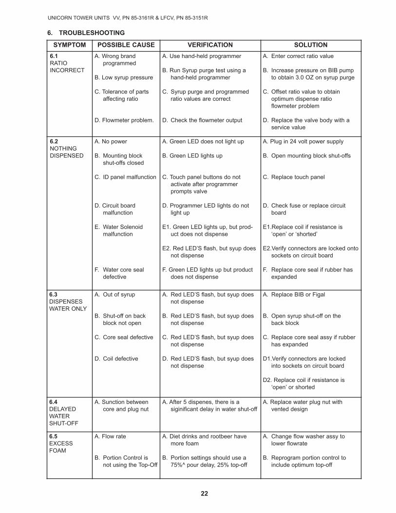
SYMPTOM POSSIBLE CAUSE VERIFICATION SOLUTION
6.1RATIOINCORRECT
A. Wrong brand programmed
B. Low syrup pressure
C. Tolerance of parts affecting ratio
D. Flowmeter problem.
A. Use hand-held programmer
B. Run Syrup purge test using ahand-held programmer
C. Syrup purge and programmedratio values are correct
D. Check the flowmeter output
A. Enter correct ratio value
B. Increase pressure on BIB pump to obtain 3.0 OZ on syrup purge
C. Offset ratio value to obtain optimum dispense ratio flowmeter problem
D. Replace the valve body with a service value
6.2NOTHING DISPENSED
A. No power
B. Mounting block shut-offs closed
C. ID panel malfunction
D. Circuit board malfunction
E. Water Solenoid malfunction
F. Water core seal defective
A. Green LED does not light up
B. Green LED lights up
C. Touch panel buttons do not activate after programmerprompts valve
D. Programmer LED lights do notlight up
E1. Green LED lights up, but prod-uct does not dispense
E2. Red LED’S flash, but syup doesnot dispense
F. Green LED lights up but productdoes not dispense
A. Plug in 24 volt power supply
B. Open mounting block shut-offs
C. Replace touch panel
D. Check fuse or replace circuitboard
E1.Replace coil if resistance is‘open’ or ‘shorted’
E2.Verify connectors are locked ontosockets on circuit board
F. Replace core seal if rubber hasexpanded
6.3DISPENSES WATER ONLY
A. Out of syrup
B. Shut-off on backblock not open
C. Core seal defective
D. Coil defective
A. Red LED’S flash, but syup doesnot dispense
B. Red LED’S flash, but syup doesnot dispense
C. Red LED’S flash, but syup doesnot dispense
D. Red LED’S flash, but syup doesnot dispense
A. Replace BIB or Figal
B. Open syrup shut-off on the back block
C. Replace core seal assy if rubberhas expanded
D1.Verify connectors are locked into sockets on circuit board
D2. Replace coil if resistance is‘open’ or shorted
6.4DELAYEDWATERSHUT- OFF
A. Sunction betweencore and plug nut
A. After 5 dispenes, there is a siginificant delay in water shut-off
A. Replace water plug nut with vented design
6.5 EXCESS FOAM
A. Flow rate
B. Portion Control isnot using the Top-Off
A. Diet drinks and rootbeer havemore foam
B. Portion settings should use a75%^ pour delay, 25% top-off
A. Change flow washer assy tolower flowrate
B. Reprogram portion control toinclude optimum top-off
6. TROUBLESHOOTING

OPERATIONS AND SERVICE MANUAL PN 28-0883/03
23
7. DISPENSER DISPOSAL
To prevent possible harm to the environment from improper disposal, recycle the unit bylocating an authorized recycle outlet or contact the retailer where the product was pur-chased. Comply with local regulations regarding disposal of the refrigerant and insulation.
8. ILLUSTRATIONS AND PARTS LISTINGS
TOwER, UNICORN, T/C, PC, CC, LFCV - SPARE PARTS LIST LIST
8.1 LFCV ELECTRONIC SPARE PARTS ...................................................................................................................24
8.2 LFCV NOZZLE SPARE PARTS ............................................................................................................................25
8.3 LFCV VALVE SPARE PARTS ...............................................................................................................................26
8.4 WIRING DIAGRAM, LFCV ...................................................................................................................................27
TOwER, UNICORN, T/C, PC, CC, VV - SPARE PARTS LIST
8.5 VV ELECTRONIC SPARE PARTS......................................................................................................................28
8.6 VV NOZZLE SPARE PARTS...............................................................................................................................29
8.7 VV WATER VALVE SPARE PARTS ....................................................................................................................30
VV SYRUP VALVE SPARE PARTS.....................................................................................................................30
8.8 VV MISC SPARE PARTS ....................................................................................................................................31
8.9 VV WIRING DIAGRAM .......................................................................................................................................32
8.10 COUNTER CUTOUT TEMPLATE .....................................................................................................................33

UNICORN TOWER UNITS VV, PN 85-3161 & LFCV, PN 85-3151
24
8.1 ELECTRONIC, LFCV SPARE PARTS
4
3
21
CALLOUT PART NUMBER QTY
01 52-3344 1
02 52-3358 1
03 64-5048/02 1
04 05-1678 4
*QTY LISTED AS PICTURED*
Item Part No. Description
1 52-3344 HARN, LFCV, THRU-CNTR VAL, UNICRN
2 52-3358 HARNESS, BYPASS, UNICORN
3 64-5048 PCB ASSY, MAIN BOARD, UNICORN
4 05-1678 STANDOFF, PCB, REV L CKNG
OPERATIONS AND SERVICE MANUAL PN 28-0883/03
25
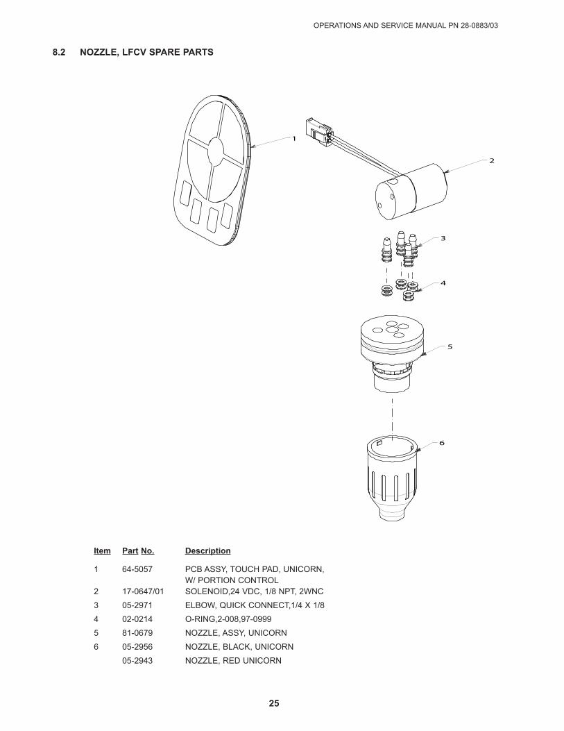
8.2 NOZZLE, LFCV SPARE PARTS
CALLOUT PART NUMBER QTY
01 64-5057 1
02 17-0647-01 1
03 05-2972 4
04 02-0214 8
05 81-0679 1
06 05-2956 1
1
2
3
4
5
6
Item Part No. Description
1 64-5057 PCB ASSY, TOUCH PAD, UNICORN,W/ PORTION CONTROL
2 17-0647/01 SOLENOID,24 VDC, 1/8 NPT, 2WNC
3 05-2971 ELBOW, qUICK CONNECT,1/4 X 1/8
4 02-0214 O-RING,2-008,97-0999
5 81-0679 NOZZLE, ASSY, UNICORN
6 05-2956 NOZZLE, BLACK, UNICORN
05-2943 NOZZLE, RED UNICORN

UNICORN TOWER UNITS VV, PN 85-3161 & LFCV, PN 85-3151
26
8.3 ELECTRONIC, LFCV SPARE PARTS
1 2
4
5
6
7
8
9
10
CA
LL
OU
TP
AR
T N
UM
BE
RQ
TY
01
01
-2
88
41
02
01
-2
80
61
03
19
-0
26
7/0
21
04
05
-1
38
51
05
02
-0
08
92
06
19
-0
26
6/0
21
07
04
-1
08
92
08
82
-2
31
7/0
11
09
02
-0
00
52
10
01
-0
01
21
*Q
TY
LIS
TE
D A
S P
ICT
UR
ED
*
Item Part No. Description
1 01-2884 FITTING, JG,3/8X1/4,REDUCER, S/FIT
2 01-2806 JG BULKHEAD CONNECTOR,3/8 S/FIT X 3/8 S/FIT,79000217
3 19-0267/02 VALVE ASSY, LFCV,2.0 SODA, GRY, S
4 05-1385 ELBOW,.5 DOLE X .2 BARB, PLS
5 02-0089 O-RING,2-012,97-0999
6 19-0266/02 VALVE ASSY, LFCV,2.0 SYR, BLK, SC
7 04-1089 SCR, 10-32,RH, PH/SL, 1.000
8 82-2317/01 BLOCK, MOUNTING ASSY, SGL
9 02-0005 O-RING ,2 -010,97-0999
10 01-0012 ADAPTOR, 1/4 BARB X DOLE
OPERATIONS AND SERVICE MANUAL PN 28-0883/03
27
UNICORN TOWER UNITS VV, PN 85-3161R & LFCV, PN 85-3151R
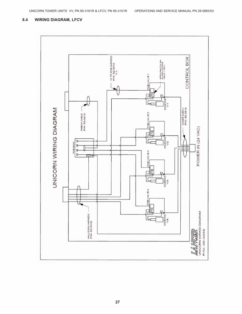
8.4 wIRING DIAGRAM, LFCV
UNICORN TOWER UNITS VV, PN 85-3161 & LFCV, PN 85-3151
28
1
2
3 4
5
6
CALLOUT PART NUMBER QTY
01 52-3381 1
02 52-3359 1
03 52-3360 1
04 52-3358 1
05 64-5048/02 1
06 05-1678 4
*QTY LISTED AS PICTURED*
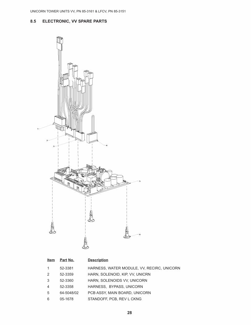
Item Part No. Description
1 52-3381 HARNESS, WATER MODULE, VV, RECIRC, UNICORN
2 52-3359 HARN, SOLENOID, KIP, VV, UNICRN
3 52-3360 HARN, SOLENOIDS VV, UNICORN
4 52-3358 HARNESS, BYPASS, UNICORN
5 64-5048/02 PCB ASSY, MAIN BOARD, UNICORN
6 05-1678 STANDOFF, PCB, REV L CKNG
8.5 ELECTRONIC, VV SPARE PARTS
OPERATIONS AND SERVICE MANUAL PN 28-0883/03
29
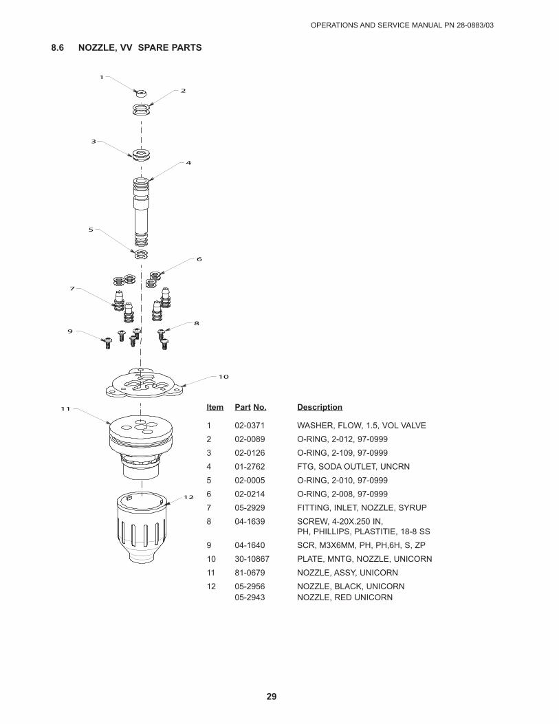
8.6 NOZZLE, VV SPARE PARTS
1
2
3
4
5
6
7
8 9
10
11
CALLOUT PART NUMBER QTY
01 02-0371 1
02 02-0089 2
03 02-0126 2
04 01-2762 1
05 02-005 2
06 02-0214 8
07 05-2929 4
08 04-1639 3
09 04-1640 3
10 30-10867 1
11 81-0679 1
12
Item Part No. Description
1 02-0371 WASHER, FLOW, 1.5, VOL VALVE
2 02-0089 O-RING, 2-012, 97-0999
3 02-0126 O-RING, 2-109, 97-0999
4 01-2762 FTG, SODA OUTLET, UNCRN
5 02-0005 O-RING, 2-010, 97-0999
6 02-0214 O-RING, 2-008, 97-0999
7 05-2929 FITTING, INLET, NOZZLE, SYRUP
8 04-1639 SCREW, 4-20X.250 IN,PH, PHILLIPS, PLASTITIE, 18-8 SS
9 04-1640 SCR, M3X6MM, PH, PH,6H, S, ZP
10 30-10867 PLATE, MNTG, NOZZLE, UNICORN
11 81-0679 NOZZLE, ASSY, UNICORN
12 05-2956 NOZZLE, BLACK, UNICORN05-2943 NOZZLE, RED UNICORN
UNICORN TOWER UNITS VV, PN 85-3161 & LFCV, PN 85-3151
30
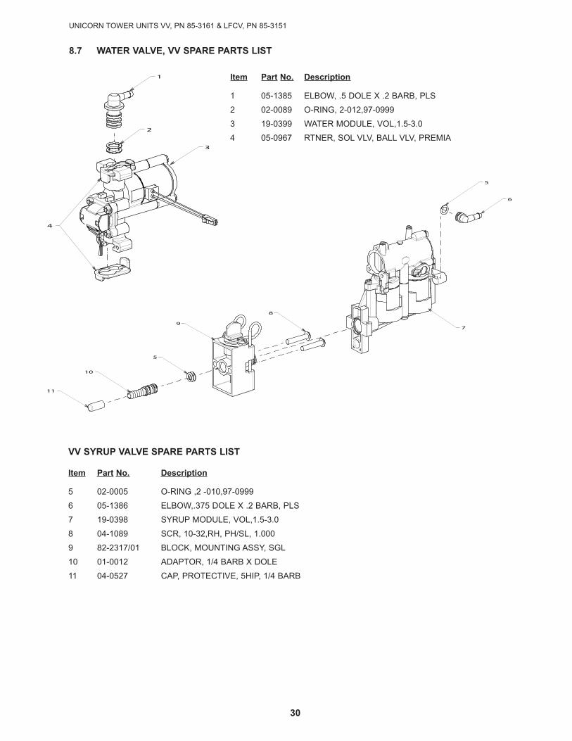
Item Part No. Description
1 05-1385 ELBOW, .5 DOLE X .2 BARB, PLS
2 02-0089 O-RING, 2-012,97-0999
3 19-0399 WATER MODULE, VOL,1.5-3.0
4 05-0967 RTNER, SOL VLV, BALL VLV, PREMIA
VV SYRUP VALVE SPARE PARTS LIST
Item Part No. Description
5 02-0005 O-RING ,2 -010,97-0999
6 05-1386 ELBOW,.375 DOLE X .2 BARB, PLS
7 19-0398 SYRUP MODULE, VOL,1.5-3.0
8 04-1089 SCR, 10-32,RH, PH/SL, 1.000
9 82-2317/01 BLOCK, MOUNTING ASSY, SGL
10 01-0012 ADAPTOR, 1/4 BARB X DOLE
11 04-0527 CAP, PROTECTIVE, 5HIP, 1/4 BARB
11
10
5
9
8
7
5
6
4
3
2
1
WATER MODULE
CALLOUT PART NUMBER QTY
01 05-1385 1
02 02-0089 2
03 19-0399 1
04 05-0967 2
SYRUP MODULE
05 02-0005 3
06 05-1386 1
07 19-0398 1
08 04-1089 2
09 82-2317/01 1
10 01-0012 1
11 04-0527 1
*QTY'S LISTED AS PICTURED*QTY 1 OF PART NUMBER05-0967 IS INCLUDEDIN THE WATER VALVE
ASSEMBLY (PART NUMBER)19-0399
8.7 wATER VALVE, VV SPARE PARTS LIST
11
10
5
9
8
7
5
6
4
3
2
1
WATER MODULE
CALLOUT PART NUMBER QTY
01 05-1385 1
02 02-0089 2
03 19-0399 1
04 05-0967 2
SYRUP MODULE
05 02-0005 3
06 05-1386 1
07 19-0398 1
08 04-1089 2
09 82-2317/01 1
10 01-0012 1
11 04-0527 1
*QTY'S LISTED AS PICTURED*QTY 1 OF PART NUMBER05-0967 IS INCLUDEDIN THE WATER VALVE
ASSEMBLY (PART NUMBER)19-0399
OPERATIONS AND SERVICE MANUAL PN 28-0883/03
31
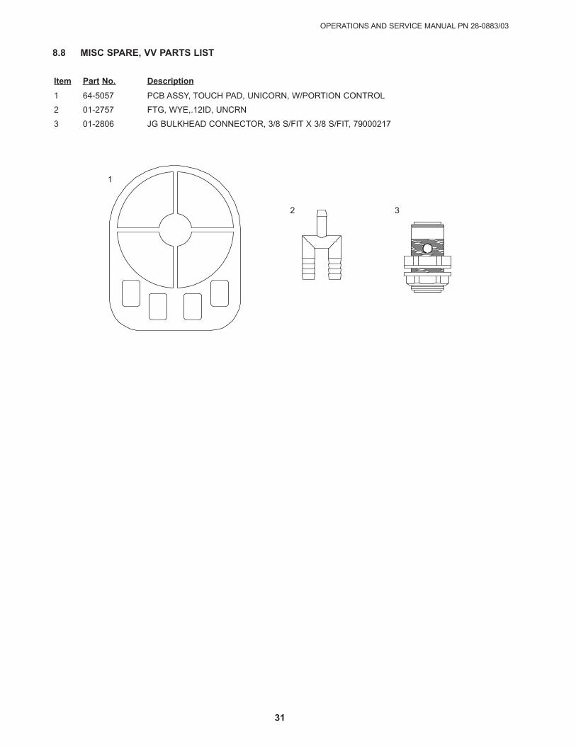
Item Part No. Description
1 64-5057 PCB ASSY, TOUCH PAD, UNICORN, W/PORTION CONTROL
2 01-2757 FTG, WYE,.12ID, UNCRN
3 01-2806 JG BULKHEAD CONNECTOR, 3/8 S/FIT X 3/8 S/FIT, 79000217
8.8 MISC SPARE, VV PARTS LIST
PART NUMBER64-5057
PART NUMBER01-2757
PART NUMBER01-28061
2 3

UNICORN TOWER UNITS VV, PN 85-3161 & LFCV, PN 85-3151
32CONTINUED ON NEXT PAGE
8.9 wIRING DIAGRAM, VV

OPERATIONS AND SERVICE MANUAL PN 28-0883/03
33
8.10 COUNTER CUTOUT TEMPLATE (not to scale)
LANCER
To order parts, call
Customer Service: 800-729-1500
warranty/Technical Support: 800-729-1550
Email: [email protected]
www.lancercorp.com