Embed Size (px)
Citation preview
Unicode™ 2 Series Customized Control StationsIncreased SafetyPolyamide, Fiberglass Reinforced Polyester, 316L Stainless Steel, Aluminum
Applications• Local control stations and motor control stations for use
in hazardous areas covering the broadest possible range of applications.
• Control of equipment at:— Power plants— Chemical and petrochemical plants— Petroleum refineries— Reverse osmosis plants— Pulp and paper processing plants— Various industrial applications
• Push buttons and selector switches are used in conjunction with contactors or magnetic starters for remote control of motors in hazardous locations. They provide circuit control and/or selection.
• Pilot lights provide visual assurance that an electrical function is being performed at a remote or hazardous location.
• For use in washdown areas.
Features• Employs Ex de method of protection which eliminates the need
for external seals.• Operators include push buttons, illuminated push buttons,
selector switches, control and load break switches and LED pilot lights.
• Pilot light employs high intensity single LED with lifetime of 100,000 hours that can be used at:
— 12 Vac to 254 Vac 50/60 Hz — 12 Vdc to 60 Vdc• Up to 3 contact blocks per actuator can be used.• Contact block technical data:
— IEC rated operating voltage (Ue): 500 Vac – 110 Vdc— IEC switching capacity: – AC 12: 16 Amps/400 Vac – AC 14: 10 Amps/400 Vac – AC 15: 6 Amps/500 Vac – DC 13: 2 Amps/24 Vdc and 1 Amp/110 Vdc— NEMA switching capacity: A600: 10 Amp/600 Vac
• Selector switch technical data:— IEC rated operating voltage: 690 Vac— IEC rated operating current: maximum 16 Amps— IEC switching capacity: – AC1: 16 Amps/690 Vac – AC15: 16 Amps/415 Vac – AC3: 8 Amps/500 Vac – AC3: 4 Amps/690 Vac – AC3: 16 Amps/690 Vac – DC1: 10 Amps/24 Vdc – DC1: 6 Amps/60 Vdc – DC1: 6 Amp/110 Vdc (2 contacts wired in series)
– DC1: 6 Amp/220 Vdc (3 contacts in series)— NEMA switching capacity: A600: 10 Amps/600 Vac
• Enclosures are rated for IP66 with firmly secured gasket.• Operators and contact blocks are spaced for easy wiring.• Wide selection of termination methods available.• Choice of DIN rail mounted high performance contact
block suitable for low intensity (less than 5 mA).• TS35 rail mounted components held securely in place
during operation and easily removed for service.• Brass Inserts are provided for TS35 DIN rails or mounting
plate to be installed inside the enclosure.
• Captive, corrosion resistant stainless steel cover screws.
Standard Materials• Polyamide
— Body, cover, cable gland and blanking plug: polyamide, black finish
• Fiberglass Reinforced Polyester (FRP)— Body and cover: fiberglass reinforced polyester, black finish
• Stainless Steel— Body, cover and cover screws: 316L stainless steel, natural
finish• Aluminum
— Body and cover: aluminum with gray epoxy powder coating.• Cable gland and blanking plug: polyamide• Cover screws for 316L stainless steel or aluminum body:
304 stainless steel• Cover screws for fiberglass reinforced polyester body:
316 stainless steel• Optional nameplates: stainless steel
Accessories• Key for changing actuator blocks.• Guard for mushroom head actuator.• Padlockable guard.• M5 and M6 earth stud.• Combination drain and breather available in brass, polyamide
and stainless steel.
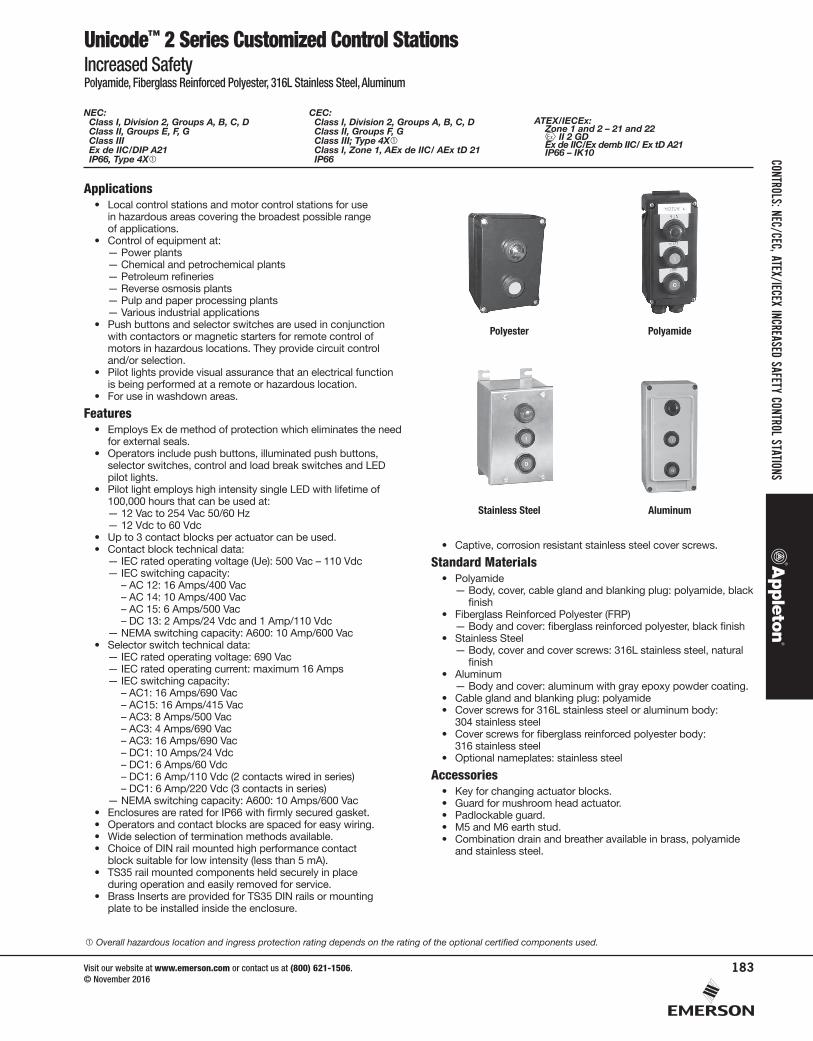
Polyester Polyamide
Stainless Steel Aluminum
Overall hazardous location and ingress protection rating depends on the rating of the optional certified components used.
NEC: Class I, Division 2, Groups A, B, C, D Class II, Groups E, F, G Class III Ex de IIC/DIP A21 IP66, Type 4X
CEC: Class I, Division 2, Groups A, B, C, D Class II, Groups F, G Class III; Type 4X Class I, Zone 1, AEx de IIC/ AEx tD 21 IP66
ATEX/IECEx: Zone 1 and 2 – 21 and 22
II 2 GD Ex de IIC/Ex demb IIC/ Ex tD A21 IP66 – IK10
CONTROLSCONTROLS: NEC/CEC, ATEX/IECEX INCREASED SAFETY CONTROL STATIONS
Visit our website at www.emerson.com or contact us at (800) 621-1506. © November 2016
183
Unicode™ 2 Series Customized Control StationsIncreased SafetyPolyamide, Fiberglass Reinforced Polyester, 316L Stainless Steel, Aluminum
Options• Nameplates: Lamacoid with different color combinations. • Padlocking facility at left, center, right or any position on
selector switches.• Padlocking facility for momentary and maintained push buttons.
NEC/CEC Certifications and Compliances• Fiberglass Reinforced Polyester (FRP)
— Certification Type CSPe — Temperature Class: T5 or T6— Ambient Temperature: -55°C to +60°C (-67°F to +140°F)— CAN/CSA Standards: C22.2 No. 0-M91, No. 25-M66, No.
213-M1987. No. 94-M91, No. 60079-0:07, No. 60529-2005, E60079-7-2003
— UL Standards: 60079-0, 60079-7, 50— Other Standards: ANSI/IEC 60529-2004, ANSI/ISA 12.12.01-
2011— cCSAus Certificate: 2356952
• Stainless Steel— Certification Type JBe — Temperature Class: T6 (at +40°C) or T5 (at +55°C)— Surface Temperature: T80 °C (at +40°C) to T95 °C
(at +55°C) (T176 °F to T203 °F)— Ambient Temperature: -40 °C to +55 °C (-40 °F to +131°F)— CAN/CSA Standard: C22.2 No. O-M91, No. 25-M66, No.
213-Ml987, No. 60079-0:07, No. 60529-2005, E60079-7-2003
— UL Standard: 60079-0, 60079-7— Other Standards: ANSl/IEC60529-2004,
ANSI/ISA 12.12.01-2011— cCSAus Certificate: 2356734
ATEX/IECEx Certification and Compliances• Polyamide
— Certification Type PCe— Gas: Zone 1 and 2
– Conforming to ATEX 94/9/CE: II 2 G– Type of Protection: Ex de IIC/Ex demb IIC– Temperature Class: T6
— Dust: Zone 21 and 22– Conforming to ATEX 94/9/CE: II2 D– Type of Protection: Ex tD A21
— Surface Temperature: T75 °C (T167 °F)— Ambient Temperature: -20 °C to +55 °C (-4 °F to +131 °F)— CE Declaration of Conformity: 50221— ATEX Certificate: LCIE 00 ATEX 6047— Index of Protection according EN/IEC 60529: IP66— Impact Resistance (shock): IK09
• Fiberglass Reinforced Polyester (FRP)— Certification Type CSPe— Gas: Zone 1 and 2
– Conforming to ATEX 94/9/CE: II 2 G– Type of Protection: Ex de IIC/Ex demb IIC– Temperature Class: T6
— Dust: Zone 21 and 22– Conforming to ATEX 94/9/CE: II2 D– Type of Protection: Ex tD A21
— Surface Temperature: T75 °C (T167 °F) — Ambient Temperature: -55 °C to +60 °C (-67°F to +140°F)
(empty enclosure, temperature to be determine according actuator)
— CE Declaration of Conformity: 52084
— ATEX Certificate: LCIE 00 ATEX 3032X— IECEx Certificate: IECEx LCI 09.0016X
• Stainless Steel— Certification Type JBe— Gas: Zone 1 and 2
– Conforming to ATEX 94/9/CE: II 2 G– Type of Protection: Ex de IIC/Ex demb IIC– Temperature Class: T5 to T6
— Dust: Zone 21 and 22– Conforming to ATEX 94/9/CE: II2 D– Type of Protection: Ex tD A21
— Surface Temperature: T80 °C to T95 °C (T176 °F to T203 °F)— Ambient Temperature: -50 °C to +70 °C (-58 °F to +158 °F)
(empty enclosure, temperature to be determine according actuator)
— CE Declaration of Conformity: 50232— ATEX Certificate: LCIE 02 ATEX 6118X— IECEx Certificate: LCI 11.0008X— Index of Protection according EN/IEC 60529: IP66— Impact Resistance (shock): IK10
• Aluminum— Certification Type PCe — Gas: Zone 1 and 2
– Conforming to ATEX 94/9/CE: II 2 G– Type of Protection: Ex de IIC/Ex demb IIC– Temperature Class: T6
— Dust: Zone 21 and 22– Conforming to ATEX 94/9/CE: II2 D– Type of Protection: Ex tD A21
— Surface Temperature: T75 °C (T167 °F)— Ambient Temperature: -55 °C to +60 °C (-67 °F to +140 °F)
(empty enclosure, temperature to be determine according actuator)
— CE Declaration of Conformity: 50221— ATEX Certificate: LCIE 02 ATEX 6047— Index of Protection according EN/IEC 60529: IP66— Impact Resistance (shock): IK10
EURASEC Certification• Certification Type PCe (Polyamide)
— EURASEC RU C-FR ГБ05.B.00911• Certification Type CSPe (Fiberglass Reinforced Polyester)
— EURASEC RU C-FR ГБ05.B.00911• Certification Type JBe (Stainless Steel)
— EURASEC RU C-FR ГБ05.B.00911• Certification Type PCe (Aluminum)
— EURASEC RU C-FR ГБ05.B.00911
Other Certification • Certification Type PCe (Polyamide)
— INMETRO Certificate: BVC 11.0640-X• Certification Type CSPe (Fiberglass Reinforced Polyester)
— INMETRO Certificate: BVC 11.0637-X• Certification Type JBe (Stainless Steel)
— INMETRO Certificate: BVC 11.0418-X
Overall hazardous location and ingress protection rating depends on the rating of the optional certified components used. INMETRO certification available on special request only. Contact your local sales representative for more information.
NEC: Class I, Division 2, Groups A, B, C, D Class II, Groups E, F, G Class III Ex de IIC/DIP A21 IP66, Type 4X
CEC: Class I, Division 2, Groups A, B, C, D Class II, Groups F, G Class III; Type 4X Class I, Zone 1, AEx de IIC/ AEx tD 21 IP66
ATEX/IECEx: Zone 1 and 2 – 21 and 22
II 2 GD Ex de IIC/Ex demb IIC/ Ex tD A21 IP66 – IK10
CONT
ROLS
CONT
ROLS
: NEC
/CEC
, ATE
X/IEC
EX IN
CREA
SED
SAFE
TY C
ONTR
OL S
TATIO
NS
Visit our website at www.emerson.com or contact us at (800) 621-1506. © November 2016
184
Unicode™ 2 Series Customized Control StationsIncreased SafetyPolyamide, Fiberglass Reinforced Polyester, 316L Stainless Steel, Aluminum
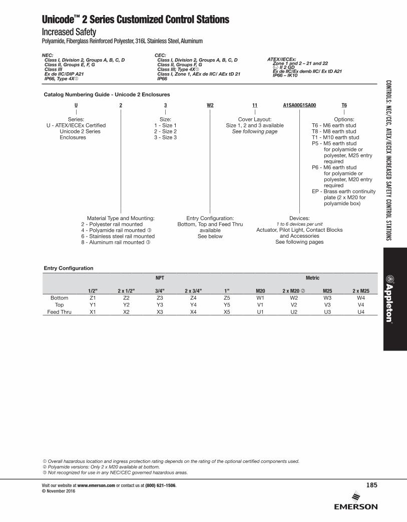
Catalog Numbering Guide - Unicode 2 Enclosures
U 2 3 W2 11 A1SA00G1SA00 T6
Series:U - ATEX/IECEx Certified
Unicode 2 Series Enclosures
Size:1 - Size 12 - Size 23 - Size 3
Cover Layout:Size 1, 2 and 3 available
See following page
Options:T6 - M6 earth studT8 - M8 earth studT1 - M10 earth studP5 - M5 earth stud
for polyamide or polyester, M25 entry required
P6 - M6 earth stud for polyamide or polyester, M20 entry required
EP - Brass earth continuity plate (2 x M20 for polyamide box)
Material Type and Mounting:2 - Polyester rail mounted4 - Polyamide rail mounted 6 - Stainless steel rail mounted8 - Aluminum rail mounted
Entry Configuration:Bottom, Top and Feed Thru
availableSee below
Devices:1 to 6 devices per unit
Actuator, Pilot Light, Contact Blocks and Accessories
See following pages
Entry Configuration
NPT Metric
1/2” 2 x 1/2” 3/4” 2 x 3/4” 1” M20 2 x M20 M25 2 x M25Bottom Z1 Z2 Z3 Z4 Z5 W1 W2 W3 W4
Top Y1 Y2 Y3 Y4 Y5 V1 V2 V3 V4Feed Thru X1 X2 X3 X4 X5 U1 U2 U3 U4
Overall hazardous location and ingress protection rating depends on the rating of the optional certified components used. Polyamide versions: Only 2 x M20 available at bottom. Not recognized for use in any NEC/CEC governed hazardous areas.
NEC: Class I, Division 2, Groups A, B, C, D Class II, Groups E, F, G Class III Ex de IIC/DIP A21 IP66, Type 4X
CEC: Class I, Division 2, Groups A, B, C, D Class II, Groups F, G Class III; Type 4X Class I, Zone 1, AEx de IIC/ AEx tD 21 IP66
ATEX/IECEx: Zone 1 and 2 – 21 and 22
II 2 GD Ex de IIC/Ex demb IIC/ Ex tD A21 IP66 – IK10
CONTROLSCONTROLS: NEC/CEC, ATEX/IECEX INCREASED SAFETY CONTROL STATIONS
Visit our website at www.emerson.com or contact us at (800) 621-1506. © November 2016
185
Unicode™ 2 Series Customized Control StationsIncreased SafetyPolyamide, Fiberglass Reinforced Polyester, 316L Stainless Steel, Aluminum
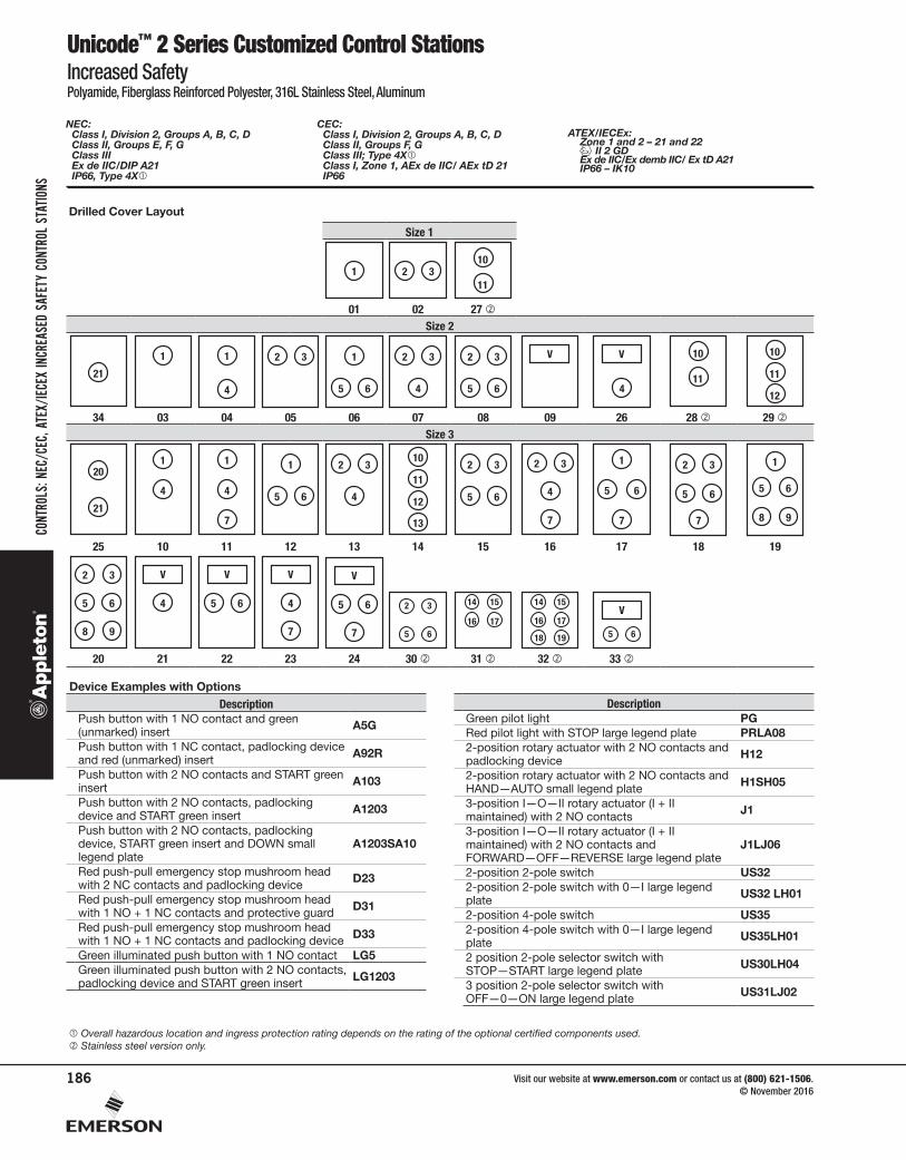
Drilled Cover Layout
Size 1
1 2 310
11
01 02 27 Size 2
21
1 1
4
32 1
65
32
4
32
65
V V
4
10
11
10
11
12
34 03 04 05 06 07 08 09 26 28 29 Size 3
20
21
1
4
1
4
7
1
5 6
2 3
4
10
11
12
13
2 3
5 6
2 3
4
7
1
5 6
7
2 3
5 6
7
5 6
1
8 9
25 10 11 12 13 14 15 16 17 18 19
2 3
5 6
8 9
V
4
V
5 6
V
4
7
V
5 6
7
2 3
5 6
14 15
16 17
14 15
18 19
16 175 6
V
20 21 22 23 24 30 31 32 33
Device Examples with OptionsDescription
Push button with 1 NO contact and green (unmarked) insert A5G
Push button with 1 NC contact, padlocking device and red (unmarked) insert A92R
Push button with 2 NO contacts and START green insert A103
Push button with 2 NO contacts, padlocking device and START green insert A1203
Push button with 2 NO contacts, padlocking device, START green insert and DOWN small legend plate
A1203SA10
Red push-pull emergency stop mushroom head with 2 NC contacts and padlocking device D23
Red push-pull emergency stop mushroom head with 1 NO + 1 NC contacts and protective guard D31
Red push-pull emergency stop mushroom head with 1 NO + 1 NC contacts and padlocking device D33
Green illuminated push button with 1 NO contact LG5Green illuminated push button with 2 NO contacts, padlocking device and START green insert LG1203
DescriptionGreen pilot light PGRed pilot light with STOP large legend plate PRLA082-position rotary actuator with 2 NO contacts and padlocking device H12
2-position rotary actuator with 2 NO contacts and HAND—AUTO small legend plate H1SH05
3-position I—O—II rotary actuator (I + II maintained) with 2 NO contacts J1
3-position I—O—II rotary actuator (I + II maintained) with 2 NO contacts and FORWARD—OFF—REVERSE large legend plate
J1LJ06
2-position 2-pole switch US322-position 2-pole switch with 0—I large legend plate US32 LH01
2-position 4-pole switch US352-position 4-pole switch with 0—I large legend plate US35LH01
2 position 2-pole selector switch with STOP—START large legend plate US30LH04
3 position 2-pole selector switch with OFF—0—ON large legend plate US31LJ02
Overall hazardous location and ingress protection rating depends on the rating of the optional certified components used. Stainless steel version only.
NEC: Class I, Division 2, Groups A, B, C, D Class II, Groups E, F, G Class III Ex de IIC/DIP A21 IP66, Type 4X
CEC: Class I, Division 2, Groups A, B, C, D Class II, Groups F, G Class III; Type 4X Class I, Zone 1, AEx de IIC/ AEx tD 21 IP66
ATEX/IECEx: Zone 1 and 2 – 21 and 22
II 2 GD Ex de IIC/Ex demb IIC/ Ex tD A21 IP66 – IK10
CONT
ROLS
CONT
ROLS
: NEC
/CEC
, ATE
X/IEC
EX IN
CREA
SED
SAFE
TY C
ONTR
OL S
TATIO
NS
Visit our website at www.emerson.com or contact us at (800) 621-1506. © November 2016
186
Unicode™ 2 Series Customized Control Station FunctionsIncreased SafetyPolyamide, Fiberglass Reinforced Polyester, 316L Stainless Steel, Aluminum
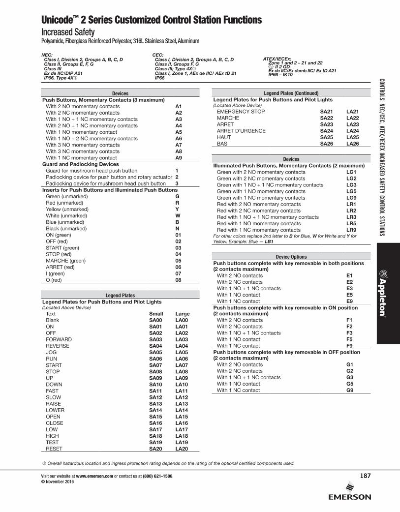
DevicesPush Buttons, Momentary Contacts (3 maximum)
With 2 NO momentary contacts A1With 2 NC momentary contacts A2With 1 NO + 1 NC momentary contacts A3With 2 NO + 1 NC momentary contacts A4With 1 NO momentary contact A5With 1 NO + 2 NC momentary contacts A6With 3 NO momentary contacts A7With 3 NC momentary contacts A8With 1 NC momentary contact A9
Guard and Padlocking DevicesGuard for mushroom head push button 1Padlocking device for push button and rotary actuator 2Padlocking device for mushroom head push button 3
Inserts for Push Buttons and Illuminated Push ButtonsGreen (unmarked) GRed (unmarked) RYellow (unmarked) YWhite (unmarked) WBlue (unmarked) BBlack (unmarked) NON (green) 01OFF (red) 02START (green) 03STOP (red) 04MARCHE (green) 05ARRET (red) 06I (green) 07O (red) 08
Legend PlatesLegend Plates for Push Buttons and Pilot Lights (Located Above Device)
Text Small LargeBlank SA00 LA00ON SA01 LA01OFF SA02 LA02FORWARD SA03 LA03REVERSE SA04 LA04JOG SA05 LA05RUN SA06 LA06START SA07 LA07STOP SA08 LA08UP SA09 LA09DOWN SA10 LA10FAST SA11 LA11SLOW SA12 LA12RAISE SA13 LA13LOWER SA14 LA14OPEN SA15 LA15CLOSE SA16 LA16LOW SA17 LA17HIGH SA18 LA18TEST SA19 LA19RESET SA20 LA20
Legend Plates (Continued)Legend Plates for Push Buttons and Pilot Lights (Located Above Device)
EMERGENCY STOP SA21 LA21MARCHE SA22 LA22ARRET SA23 LA23ARRET D’URGENCE SA24 LA24HAUT SA25 LA25BAS SA26 LA26
DevicesIlluminated Push Buttons, Momentary Contacts (2 maximum)
Green with 2 NO momentary contacts LG1Green with 2 NC momentary contacts LG2Green with 1 NO + 1 NC momentary contacts LG3Green with 1 NO momentary contacts LG5Green with 1 NC momentary contacts LG9Red with 2 NO momentary contacts LR1Red with 2 NC momentary contacts LR2Red with 1 NO + 1 NC momentary contacts LR3Red with 1 NO momentary contacts LR5Red with 1 NC momentary contacts LR9
For other colors replace 2nd letter to B for Blue, W for White and Y for Yellow. Example: Blue — LB1
Device OptionsPush buttons complete with key removable in both positions (2 contacts maximum)
With 2 NO contacts E1With 2 NC contacts E2With 1 NO + 1 NC contacts E3With 1 NO contact E5With 1 NC contact E9
Push buttons complete with key removable in ON position(2 contacts maximum)
With 2 NO contacts F1With 2 NC contacts F2With 1 NO + 1 NC contacts F3With 1 NO contact F5With 1 NC contact F9
Push buttons complete with key removable in OFF position(2 contacts maximum)
With 2 NO contacts G1With 2 NC contacts G2With 1 NO + 1 NC contacts G3With 1 NO contact G5With 1 NC contact G9
Overall hazardous location and ingress protection rating depends on the rating of the optional certified components used.
NEC: Class I, Division 2, Groups A, B, C, D Class II, Groups E, F, G Class III Ex de IIC/DIP A21 IP66, Type 4X
CEC: Class I, Division 2, Groups A, B, C, D Class II, Groups F, G Class III; Type 4X Class I, Zone 1, AEx de IIC/ AEx tD 21 IP66
ATEX/IECEx: Zone 1 and 2 – 21 and 22
II 2 GD Ex de IIC/Ex demb IIC/ Ex tD A21 IP66 – IK10
CONTROLSCONTROLS: NEC/CEC, ATEX/IECEX INCREASED SAFETY CONTROL STATIONS
Visit our website at www.emerson.com or contact us at (800) 621-1506. © November 2016
187
Unicode™ 2 Series Customized Control Station FunctionsIncreased SafetyPolyamide, Fiberglass Reinforced Polyester, 316L Stainless Steel, Aluminum
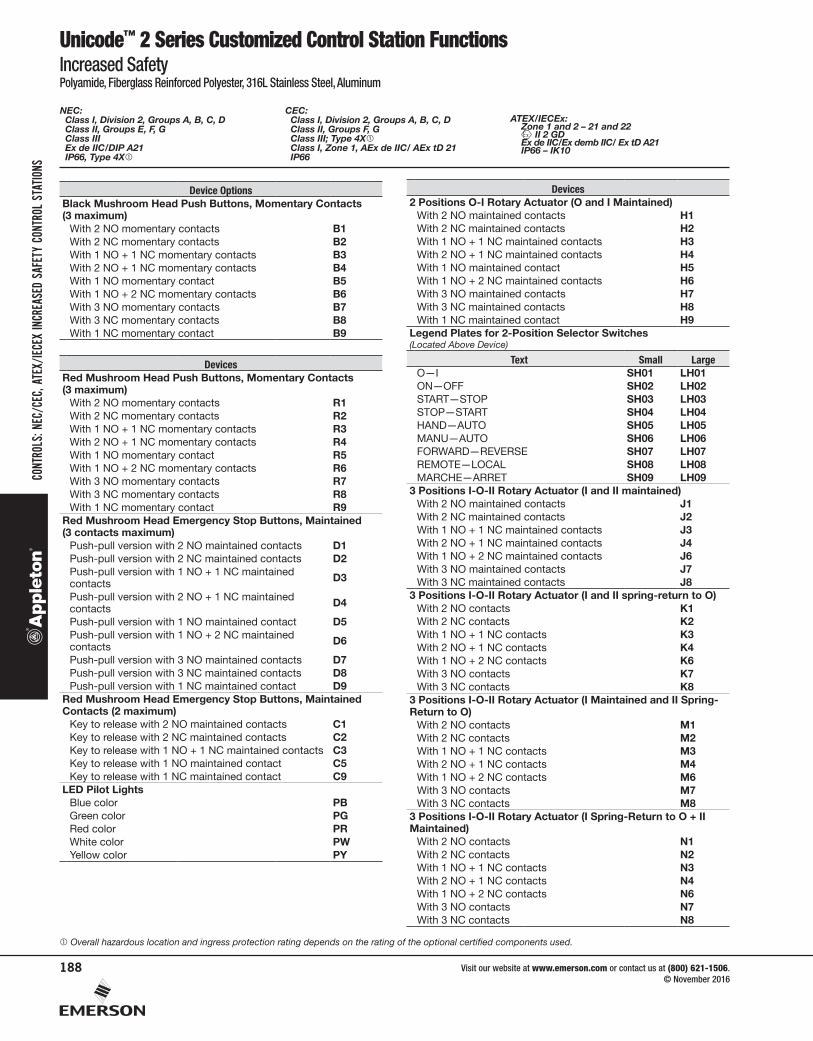
Device OptionsBlack Mushroom Head Push Buttons, Momentary Contacts (3 maximum)
With 2 NO momentary contacts B1With 2 NC momentary contacts B2With 1 NO + 1 NC momentary contacts B3With 2 NO + 1 NC momentary contacts B4With 1 NO momentary contact B5With 1 NO + 2 NC momentary contacts B6With 3 NO momentary contacts B7With 3 NC momentary contacts B8With 1 NC momentary contact B9
DevicesRed Mushroom Head Push Buttons, Momentary Contacts (3 maximum)
With 2 NO momentary contacts R1With 2 NC momentary contacts R2With 1 NO + 1 NC momentary contacts R3With 2 NO + 1 NC momentary contacts R4With 1 NO momentary contact R5With 1 NO + 2 NC momentary contacts R6With 3 NO momentary contacts R7With 3 NC momentary contacts R8With 1 NC momentary contact R9
Red Mushroom Head Emergency Stop Buttons, Maintained (3 contacts maximum)
Push-pull version with 2 NO maintained contacts D1Push-pull version with 2 NC maintained contacts D2Push-pull version with 1 NO + 1 NC maintained contacts D3
Push-pull version with 2 NO + 1 NC maintained contacts D4
Push-pull version with 1 NO maintained contact D5Push-pull version with 1 NO + 2 NC maintained contacts D6
Push-pull version with 3 NO maintained contacts D7Push-pull version with 3 NC maintained contacts D8Push-pull version with 1 NC maintained contact D9
Red Mushroom Head Emergency Stop Buttons, Maintained Contacts (2 maximum)
Key to release with 2 NO maintained contacts C1Key to release with 2 NC maintained contacts C2Key to release with 1 NO + 1 NC maintained contacts C3Key to release with 1 NO maintained contact C5Key to release with 1 NC maintained contact C9
LED Pilot LightsBlue color PBGreen color PGRed color PRWhite color PWYellow color PY
Devices2 Positions O-I Rotary Actuator (O and I Maintained)
With 2 NO maintained contacts H1With 2 NC maintained contacts H2With 1 NO + 1 NC maintained contacts H3With 2 NO + 1 NC maintained contacts H4With 1 NO maintained contact H5With 1 NO + 2 NC maintained contacts H6With 3 NO maintained contacts H7With 3 NC maintained contacts H8With 1 NC maintained contact H9
Legend Plates for 2-Position Selector Switches (Located Above Device)
Text Small LargeO—I SH01 LH01ON—OFF SH02 LH02START—STOP SH03 LH03STOP—START SH04 LH04HAND—AUTO SH05 LH05MANU—AUTO SH06 LH06FORWARD—REVERSE SH07 LH07REMOTE—LOCAL SH08 LH08MARCHE—ARRET SH09 LH09
3 Positions I-O-II Rotary Actuator (I and II maintained)With 2 NO maintained contacts J1With 2 NC maintained contacts J2With 1 NO + 1 NC maintained contacts J3With 2 NO + 1 NC maintained contacts J4With 1 NO + 2 NC maintained contacts J6With 3 NO maintained contacts J7With 3 NC maintained contacts J8
3 Positions I-O-II Rotary Actuator (I and II spring-return to O)With 2 NO contacts K1With 2 NC contacts K2With 1 NO + 1 NC contacts K3With 2 NO + 1 NC contacts K4With 1 NO + 2 NC contacts K6With 3 NO contacts K7With 3 NC contacts K8
3 Positions I-O-II Rotary Actuator (I Maintained and II Spring-Return to O)
With 2 NO contacts M1With 2 NC contacts M2With 1 NO + 1 NC contacts M3With 2 NO + 1 NC contacts M4With 1 NO + 2 NC contacts M6With 3 NO contacts M7With 3 NC contacts M8
3 Positions I-O-II Rotary Actuator (I Spring-Return to O + II Maintained)
With 2 NO contacts N1With 2 NC contacts N2With 1 NO + 1 NC contacts N3With 2 NO + 1 NC contacts N4With 1 NO + 2 NC contacts N6With 3 NO contacts N7With 3 NC contacts N8
Overall hazardous location and ingress protection rating depends on the rating of the optional certified components used.
NEC: Class I, Division 2, Groups A, B, C, D Class II, Groups E, F, G Class III Ex de IIC/DIP A21 IP66, Type 4X
CEC: Class I, Division 2, Groups A, B, C, D Class II, Groups F, G Class III; Type 4X Class I, Zone 1, AEx de IIC/ AEx tD 21 IP66
ATEX/IECEx: Zone 1 and 2 – 21 and 22
II 2 GD Ex de IIC/Ex demb IIC/ Ex tD A21 IP66 – IK10
CONT
ROLS
CONT
ROLS
: NEC
/CEC
, ATE
X/IEC
EX IN
CREA
SED
SAFE
TY C
ONTR
OL S
TATIO
NS
Visit our website at www.emerson.com or contact us at (800) 621-1506. © November 2016
188
Unicode™ 2 Series Customized Control Station FunctionsIncreased SafetyPolyamide, Fiberglass Reinforced Polyester, 316L Stainless Steel, Aluminum
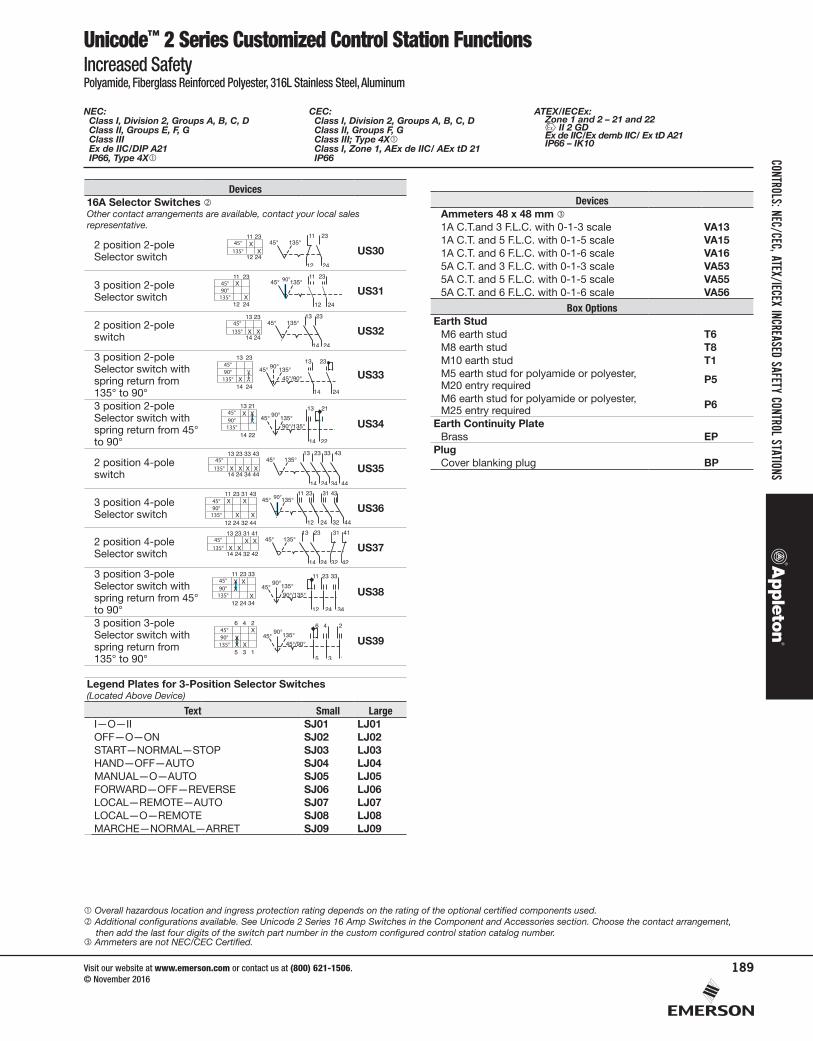
Devices16A Selector Switches Other contact arrangements are available, contact your local sales representative.
2 position 2-poleSelector switch US30
3 position 2-poleSelector switch US31
2 position 2-pole switch US32
3 position 2-poleSelector switch withspring return from 135° to 90°
US33
3 position 2-poleSelector switch with spring return from 45° to 90°
US34
2 position 4-pole switch US35
3 position 4-poleSelector switch US36
2 position 4-poleSelector switch US37
3 position 3-poleSelector switch with spring return from 45° to 90°
US38
3 position 3-poleSelector switch with spring return from 135° to 90°
US39
Legend Plates for 3-Position Selector Switches (Located Above Device)
Text Small LargeI—O—II SJ01 LJ01OFF—O—ON SJ02 LJ02START—NORMAL—STOP SJ03 LJ03HAND—OFF—AUTO SJ04 LJ04MANUAL—O—AUTO SJ05 LJ05FORWARD—OFF—REVERSE SJ06 LJ06LOCAL—REMOTE—AUTO SJ07 LJ07LOCAL—O—REMOTE SJ08 LJ08MARCHE—NORMAL—ARRET SJ09 LJ09
Overall hazardous location and ingress protection rating depends on the rating of the optional certified components used. Additional configurations available. See Unicode 2 Series 16 Amp Switches in the Component and Accessories section. Choose the contact arrangement,
then add the last four digits of the switch part number in the custom configured control station catalog number. Ammeters are not NEC/CEC Certified.
NEC: Class I, Division 2, Groups A, B, C, D Class II, Groups E, F, G Class III Ex de IIC/DIP A21 IP66, Type 4X
CEC: Class I, Division 2, Groups A, B, C, D Class II, Groups F, G Class III; Type 4X Class I, Zone 1, AEx de IIC/ AEx tD 21 IP66
ATEX/IECEx: Zone 1 and 2 – 21 and 22
II 2 GD Ex de IIC/Ex demb IIC/ Ex tD A21 IP66 – IK10
DevicesAmmeters 48 x 48 mm 1A C.T.and 3 F.L.C. with 0-1-3 scale VA131A C.T. and 5 F.L.C. with 0-1-5 scale VA151A C.T. and 6 F.L.C. with 0-1-6 scale VA165A C.T. and 3 F.L.C. with 0-1-3 scale VA535A C.T. and 5 F.L.C. with 0-1-5 scale VA555A C.T. and 6 F.L.C. with 0-1-6 scale VA56
Box OptionsEarth Stud
M6 earth stud T6M8 earth stud T8M10 earth stud T1M5 earth stud for polyamide or polyester, M20 entry required P5
M6 earth stud for polyamide or polyester, M25 entry required P6
Earth Continuity PlateBrass EP
PlugCover blanking plug BP
CONTROLSCONTROLS: NEC/CEC, ATEX/IECEX INCREASED SAFETY CONTROL STATIONS
Visit our website at www.emerson.com or contact us at (800) 621-1506. © November 2016
189
Unicode™ 2 Series Customized Control Stations Ordering ExampleIncreased SafetyPolyamide, Fiberglass Reinforced Polyester, 316L Stainless Steel, Aluminum
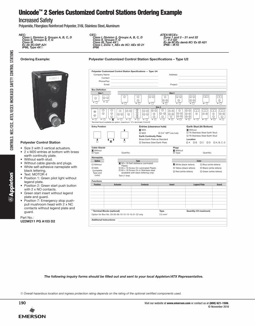
Ordering Example: Polyester Customized Control Station Specifications – Type U2
N
Polyester Customized Control Station Specifications — Type: U4
:sserddA:emaN ynapmoC
Contact:
Phone/Fax:
:tcejorP:liamE
Box Definition
2 eziS1 eziS
1
01
2 3
0203 *
1
04
1
4
05 *
32
06
1
65
07
32
4
08
32
65
09 *
V
26
V
4
Size 3
25
20
21
10 *
1
4
11
1
4
7
12 *
1
5 6
13 *
2 3
4
14
10
11
12
13
15 *
2 3
5 6
16
2 3
4
7
17
1
5 6
7
18
2 3
5 6
7
19
5 6
1
8 9
20
2 3
5 6
8 9
V
21 *
4
V
22 *
5 6
V
23
4
7
V
24
5 6
7
* Terminal block available as option. (maximum: 10 x terminals 2.5mm2)
Entry Position Entries (clearance hole) Earth Stud (At Bottom)� M20 � Without
� M25 � 3/4" NPT (via hub) � T6 Stainless Steel Earth Stud
Earth Continuity Plate � T8 Stainless Steel Earth Stud
Brass Earth Plate as Standard Location
� Stainless Steel Earth Plate � A � B � C � D � A, B, C, D
sgulPsdnalG elbaC� Without � Without� Type: Quantity: � Type: Quantity:
Nameplate
roloCepyTnoitpO
� Without � 58 x 18 Self-Adhesive Laminated Plastic � White (black letters) � Blue (white letters)
� With(complete Type and
color)
� 65 x 18 Screw On Laminated Plastic � Yellow (black letters) � Black (white letters)� 65 x 18 Screw On in Stainless steel
(available with black lettering only) � Red (white letters) � Green (white letters)
Text (1 line):
Functions
Position Actuator Contacts Insert Legend Plate Guard
)mumixam 01( ytitnauQepyT)lanoitpo( skcolB lanimreT *
Option for Box No. 03-05-09-10-12-13-15-21-22 only 2.5 mm2
Additional Instructions:
X
X X
X
XX
X X
Polyester Control Station
• Size 3 with 3 vertical actuators.• 2 x M20 entries at bottom with brass
earth continuity plate.• Without earth stud.• Without cable glands and plugs.• White self-adhesive nameplate with
black lettering.• Text: MOTOR 4• Position 1: Green pilot light without
legend plate.• Position 2: Green start push button
with 2 x NO contacts.• Green start insert without legend
plate and guard.• Position 7: Emergency stop push-
pull mushroom head with 2 x NC contacts without legend plate and guard.
Part No.:U23W211 PG A103 D2
The following inquiry forms should be filled out and sent to your local Appleton/ATX Representative.
Overall hazardous location and ingress protection rating depends on the rating of the optional certified components used.
NEC: Class I, Division 2, Groups A, B, C, D Class II, Groups E, F, G Class III Ex de IIC/DIP A21 IP66, Type 4X
CEC: Class I, Division 2, Groups A, B, C, D Class II, Groups F, G Class III; Type 4X Class I, Zone 1, AEx de IIC/ AEx tD 21 IP66
ATEX/IECEx: Zone 1 and 2 – 21 and 22
II 2 GD Ex de IIC/Ex demb IIC/ Ex tD A21 IP66 – IK10
CONT
ROLS
CONT
ROLS
: NEC
/CEC
, ATE
X/IEC
EX IN
CREA
SED
SAFE
TY C
ONTR
OL S
TATIO
NS
Visit our website at www.emerson.com or contact us at (800) 621-1506. © November 2016
190
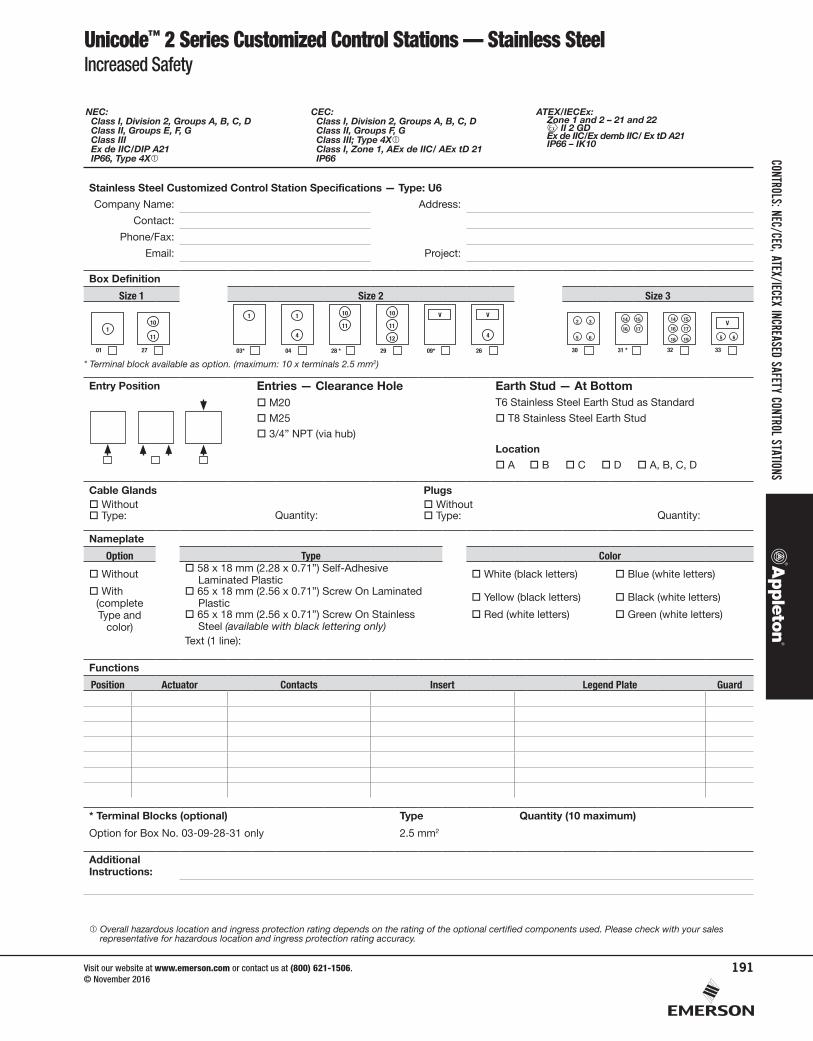
Unicode™ 2 Series Customized Control Stations — Stainless SteelIncreased Safety
Stainless Steel Customized Control Station Specifications — Type: U6
Company Name: Address:
Contact:
Phone/Fax:
Email: Project:
Box Definition
Size 1 Size 2 Size 3
1
01
10
11
27 03*
1
04
1
4
28 *
11
10
29
11
10
12
09*
V
26
V
4
30
2 3
5 6
31 *
14 15
16 17
32
14 15
18 19
16 17
33
5 6
V
* Terminal block available as option. (maximum: 10 x terminals 2.5 mm2)
Entry Position Entries — Clearance Hole Earth Stud — At Bottom M20 T6 Stainless Steel Earth Stud as Standard
M25 T8 Stainless Steel Earth Stud
3/4” NPT (via hub)Location
A B C D A, B, C, D
Cable Glands Plugs Without Without Type: Quantity: Type: Quantity:
Nameplate
Option Type Color
Without 58 x 18 mm (2.28 x 0.71”) Self-Adhesive Laminated Plastic White (black letters) Blue (white letters)
With(complete Type and
color)
65 x 18 mm (2.56 x 0.71”) Screw On Laminated Plastic Yellow (black letters) Black (white letters)
65 x 18 mm (2.56 x 0.71”) Screw On Stainless Steel (available with black lettering only)
Red (white letters) Green (white letters)
Text (1 line):
Functions
Position Actuator Contacts Insert Legend Plate Guard
* Terminal Blocks (optional) Type Quantity (10 maximum)
Option for Box No. 03-09-28-31 only 2.5 mm2
Additional Instructions:
Overall hazardous location and ingress protection rating depends on the rating of the optional certified components used. Please check with your sales representative for hazardous location and ingress protection rating accuracy.
NEC: Class I, Division 2, Groups A, B, C, D Class II, Groups E, F, G Class III Ex de IIC/DIP A21 IP66, Type 4X
CEC: Class I, Division 2, Groups A, B, C, D Class II, Groups F, G Class III; Type 4X Class I, Zone 1, AEx de IIC/ AEx tD 21 IP66
ATEX/IECEx: Zone 1 and 2 – 21 and 22
II 2 GD Ex de IIC/Ex demb IIC/ Ex tD A21 IP66 – IK10
CONTROLSCONTROLS: NEC/CEC, ATEX/IECEX INCREASED SAFETY CONTROL STATIONS
Visit our website at www.emerson.com or contact us at (800) 621-1506. © November 2016
191
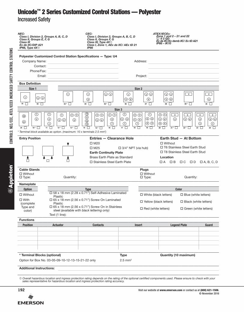
Unicode™ 2 Series Customized Control Stations — PolyesterIncreased Safety
Polyester Customized Control Station Specifications — Type: U4
Company Name: Address:
Contact:
Phone/Fax:
Email: Project:
Box Definition
Size 1 Size 2
1
01
2 3
02 03 *
1
04
1
4
05 *
32
06
1
65
07
32
4
08
32
65
09 *
V
26
V
4
Size 3
25
20
21
10 *
1
4
11
1
4
7
12 *
1
5 6
13 *
2 3
4
14
10
11
12
13
15 *
2 3
5 6
16
2 3
4
7
17
1
5 6
7
18
2 3
5 6
7
19
5 6
1
8 9
20
2 3
5 6
8 9
V
21 *
4
V
22 *
5 6
V
23
4
7
V
24
5 6
7
* Terminal block available as option. (maximum: 10 x terminals 2.5 mm2)
Entry Position Entries — Clearance Hole Earth Stud — At Bottom M20 Without
M25 3/4” NPT (via hub) T6 Stainless Steel Earth Stud
Earth Continuity Plate T8 Stainless Steel Earth Stud
Brass Earth Plate as Standard Location
Stainless Steel Earth Plate A B C D A, B, C, D
Cable Glands Plugs Without Without Type: Quantity: Type: Quantity:
Nameplate
Option Type Color
Without 58 x 18 mm (2.28 x 0.71”) Self-Adhesive Laminated Plastic White (black letters) Blue (white letters)
With(complete Type and
color)
65 x 18 mm (2.56 x 0.71”) Screw On Laminated Plastic Yellow (black letters) Black (white letters)
65 x 18 mm (2.56 x 0.71”) Screw On in Stainless steel (available with black lettering only) Red (white letters) Green (white letters)
Text (1 line):
Functions
Position Actuator Contacts Insert Legend Plate Guard
* Terminal Blocks (optional) Type Quantity (10 maximum)
Option for Box No. 03-05-09-10-12-13-15-21-22 only 2.5 mm2
Additional Instructions:
Overall hazardous location and ingress protection rating depends on the rating of the optional certified components used. Please ensure to check with your sales representative for hazardous location and ingress protection rating accuracy.
NEC: Class I, Division 2, Groups A, B, C, D Class II, Groups E, F, G Class III Ex de IIC/DIP A21 IP66, Type 4X
CEC: Class I, Division 2, Groups A, B, C, D Class II, Groups F, G Class III; Type 4X Class I, Zone 1, AEx de IIC/ AEx tD 21 IP66
ATEX/IECEx: Zone 1 and 2 – 21 and 22
II 2 GD Ex de IIC/Ex demb IIC/ Ex tD A21 IP66 – IK10
CONT
ROLS
CONT
ROLS
: NEC
/CEC
, ATE
X/IEC
EX IN
CREA
SED
SAFE
TY C
ONTR
OL S
TATIO
NS
Visit our website at www.emerson.com or contact us at (800) 621-1506. © November 2016
192
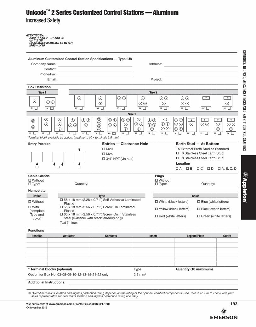
Unicode™ 2 Series Customized Control Stations — AluminumIncreased Safety
Aluminum Customized Control Station Specifications — Type: U8
Company Name: Address:
Contact:
Phone/Fax:
Email: Project:
Box Definition
Size 1 Size 2
1
01
2 3
02 03 *
1
04
1
4
05 *
32
06
1
65
07
32
4
08
32
65
09 *
V
26
V
4
Size 3
25
20
21
10 *
1
4
11
1
4
7
12 *
1
5 6
13 *
2 3
4
14
10
11
12
13
15 *
2 3
5 6
16
2 3
4
7
17
1
5 6
7
18
2 3
5 6
7
19
5 6
1
8 9
20
2 3
5 6
8 9
V
21 *
4
V
22 *
5 6
V
23
4
7
V
24
5 6
7
* Terminal block available as option. (maximum: 10 x terminals 2.5 mm2)
Entry Position Entries — Clearance Hole Earth Stud — At Bottom M20 T5 External Earth Stud as Standard
M25 T6 Stainless Steel Earth Stud
3/4” NPT (via hub) T8 Stainless Steel Earth Stud
Location
A B C D A, B, C, D
Cable Glands Plugs Without Without Type: Quantity: Type: Quantity:
Nameplate
Option Type Color
Without 58 x 18 mm (2.28 x 0.71”) Self-Adhesive Laminated Plastic White (black letters) Blue (white letters)
With(complete Type and
color)
65 x 18 mm (2.56 x 0.71”) Screw On Laminated Plastic Yellow (black letters) Black (white letters)
65 x 18 mm (2.56 x 0.71”) Screw On in Stainless steel (available with black lettering only) Red (white letters) Green (white letters)
Text (1 line):
Functions
Position Actuator Contacts Insert Legend Plate Guard
* Terminal Blocks (optional) Type Quantity (10 maximum)
Option for Box No. 03-05-09-10-12-13-15-21-22 only 2.5 mm2
Additional Instructions:
Overall hazardous location and ingress protection rating depends on the rating of the optional certified components used. Please ensure to check with your sales representative for hazardous location and ingress protection rating accuracy.
ATEX/IECEx: Zone 1 and 2 – 21 and 22
II 2 GD Ex de IIC/Ex demb IIC/ Ex tD A21 IP66 – IK10
CONTROLSCONTROLS: NEC/CEC, ATEX/IECEX INCREASED SAFETY CONTROL STATIONS
Visit our website at www.emerson.com or contact us at (800) 621-1506. © November 2016
193
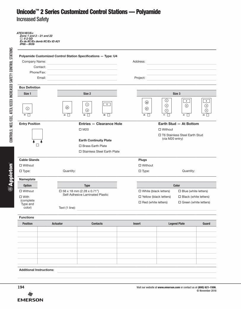
ATEX/IECEx: Zone 1 and 2 – 21 and 22
II 2 GD Ex de IIC/Ex demb IIC/Ex tD A21 IP66 – IK09
Unicode™ 2 Series Customized Control Stations — PolyamideIncreased Safety
Polyamide Customized Control Station Specifications — Type: U4
Company Name: Address:
Contact:
Phone/Fax:
Email: Project:
Box Definition
Size 1 Size 2 Size 3
1
01 34
21
04
1
4
09
V
25
20
21
11
1
4
7
21
V
4
23
V
4
7
Entry Position Entries — Clearance Hole Earth Stud — At Bottom
M20 Without
T6 Stainless Steel Earth Stud (via M20 entry)Earth Continuity Plate
Brass Earth Plate
Stainless Steel Earth Plate
Cable Glands Plugs
Without Without
Type: Quantity: Type: Quantity:
Nameplate
Option Type Color
Without 58 x 18 mm (2.28 x 0.71”) Self-Adhesive Laminated Plastic
White (black letters) Blue (white letters)
With(complete Type and
color)
Yellow (black letters) Black (white letters)
Red (white letters) Green (white letters)
Text (1 line):
Functions
Position Actuator Contacts Insert Legend Plate Guard
Additional Instructions:
CONT
ROLS
CONT
ROLS
: NEC
/CEC
, ATE
X/IEC
EX IN
CREA
SED
SAFE
TY C
ONTR
OL S
TATIO
NS
Visit our website at www.emerson.com or contact us at (800) 621-1506. © November 2016
194