Embed Size (px)
Citation preview
Frankfurt – October 2008, 20th
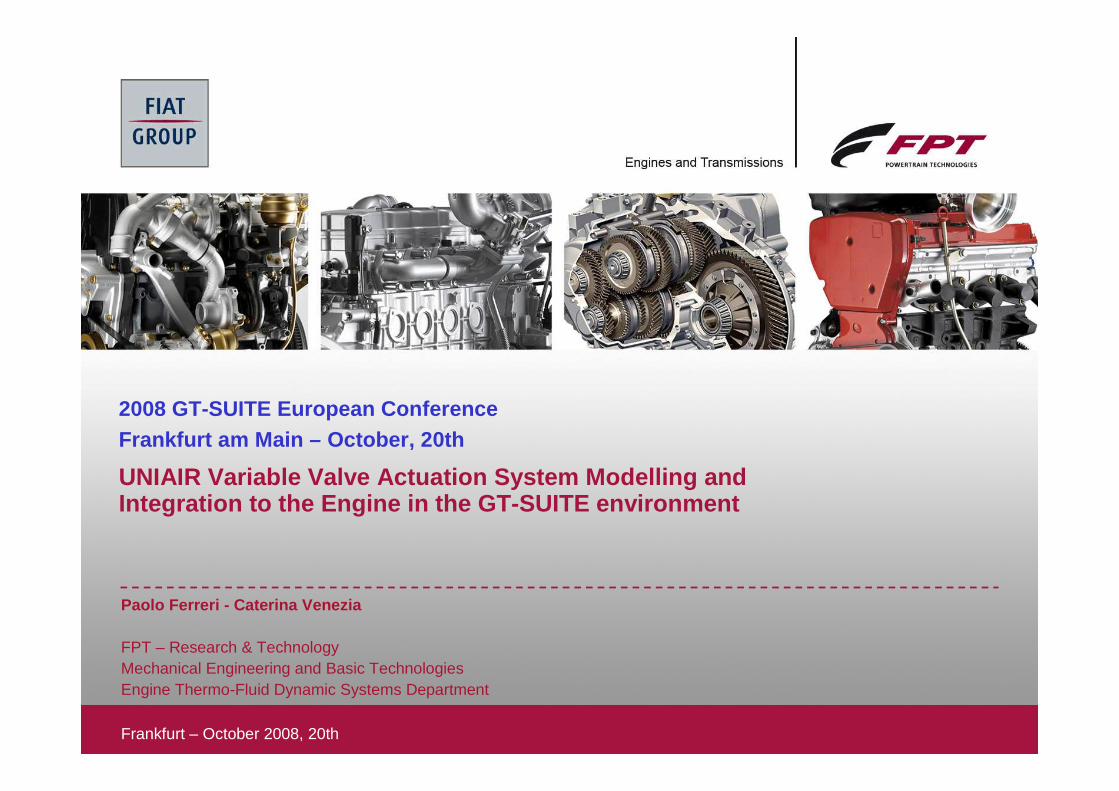
UNIAIR Variable Valve Actuation System Modelling and Integration to the Engine in the GT-SUITE environme nt
Paolo Ferreri - Caterina Venezia
FPT – Research & TechnologyMechanical Engineering and Basic TechnologiesEngine Thermo-Fluid Dynamic Systems Department
2008 GT-SUITE European ConferenceFrankfurt am Main – October, 20th
UNIAIR Variable Valve Actuation System Modelling andIntegration to the Engine in the GT -SUITE environment
2October 2008, 20th
Contents
• Introduction
• The UNIAIR actuator technology
• Modelling of the UNIAIR actuator in the GT-SUITE environment
• Comparison between simulation results and experimental data
• Integration of the actuator model (GT-FUEL) to the engine one (GT-Power)
• Sample analysis using the integrated model
• Final remarks and conclusions
Contents
Introduction
UNIAIR Technology
GT-SUITE actuator
modelling
Simulations vsexperiments
Actuator model to Engine
model integration
Sample analysis using the integrated
model
Final remarks and
conclusions
UNIAIR Variable Valve Actuation System Modelling andIntegration to the Engine in the GT -SUITE environment
3October 2008, 20th
Introduction
• Activity objectives
• development of a model of the UNIAIR variable valve actuation system in the GT-SUITE environment
• integration of the actuator model to the engine one in a unique environment
• Integrated simulations: why ?
• simulation, in engine applications characterized by additional cam lobes likeinternal EGR lobes and engine braking lobes, of the effect on the UNIAIR valve lift of the gas pressures, variable with engine speed and load
• Integrated simulations: to do what ?
• internal EGR analyses
• engine braking analyses• actuator design optimization
Contents
Introduction
UNIAIR Technology
GT-SUITE actuator
modelling
Simulations vsexperiments
Actuator model to Engine
model integration
Sample analysis using the integrated
model
Final remarks and
conclusions
UNIAIR Variable Valve Actuation System Modelling andIntegration to the Engine in the GT -SUITE environment
4October 2008, 20th
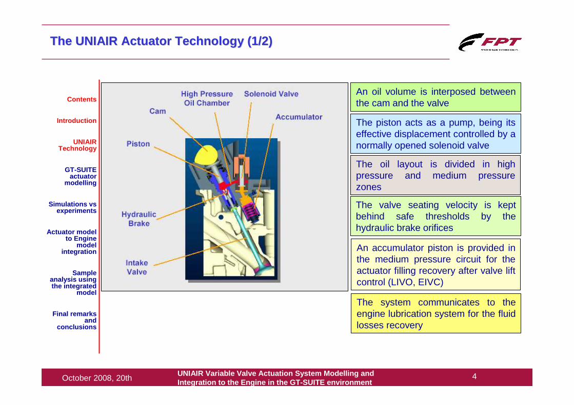
The UNIAIR Actuator Technology (1/2)The UNIAIR Actuator Technology (1/2)
An oil volume is interposed between the cam and the valve
The piston acts as a pump, being its effective displacement controlled by a normally opened solenoid valve
The oil layout is divided in high pressure and medium pressure zones
The valve seating velocity is kept behind safe thresholds by the hydraulic brake orifices
An accumulator piston is provided in the medium pressure circuit for the actuator filling recovery after valve lift control (LIVO, EIVC)
The system communicates to the engine lubrication system for the fluid losses recovery
Contents
Introduction
UNIAIR Technology
GT-SUITE actuator
modelling
Simulations vsexperiments
Actuator model to Engine
model integration
Sample analysis using the integrated
model
Final remarks and
conclusions
UNIAIR Variable Valve Actuation System Modelling andIntegration to the Engine in the GT -SUITE environment
5October 2008, 20th
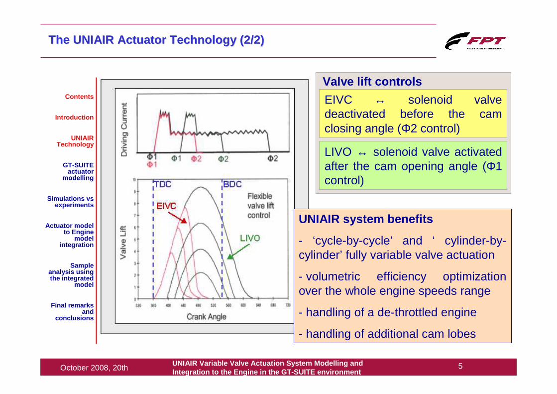
The UNIAIR Actuator Technology (2/2)The UNIAIR Actuator Technology (2/2)
EIVC ↔ solenoid valve deactivated before the cam closing angle (Φ2 control)
LIVO ↔ solenoid valve activated after the cam opening angle (Φ1 control)
Valve lift controlsContents
Introduction
UNIAIR Technology
GT-SUITE actuator
modelling
Simulations vsexperiments
Actuator model to Engine
model integration
Sample analysis using the integrated
model
Final remarks and
conclusions
UNIAIR system benefits
- ‘cycle-by-cycle’ and ‘ cylinder-by-cylinder’ fully variable valve actuation
- volumetric efficiency optimization over the whole engine speeds range
- handling of a de-throttled engine
- handling of additional cam lobes
UNIAIR Variable Valve Actuation System Modelling andIntegration to the Engine in the GT -SUITE environment
6October 2008, 20th
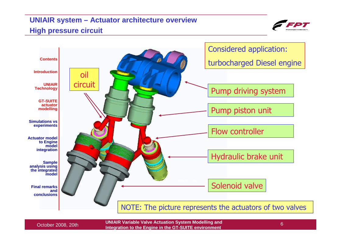
NOTE: The picture represents the actuators of two valves
Pump piston unit
Hydraulic brake unit
Flow controller
Pump driving system
Solenoid valve
UNIAIR system – Actuator architecture overviewHigh pressure circuit
Considered application:
turbocharged Diesel engineContents
Introduction
UNIAIR Technology
GT-SUITE actuator
modelling
Simulations vsexperiments
Actuator model to Engine
model integration
Sample analysis using the integrated
model
Final remarks and
conclusions
oil circuit

UNIAIR Variable Valve Actuation System Modelling andIntegration to the Engine in the GT -SUITE environment
7October 2008, 20th
GT-SUITE sketch of the UNIAIR Variable Valve Actuat ion System
pump piston unit
solenoid valve
flow controller
accumulator unit
inlet check valve
oil supply
valve unit
HLA
hydraulic brake unit
oil circuit
gas pressures interface
Contents
Introduction
UNIAIR Technology
GT-SUITE actuator
modelling
Simulations vsexperiments
Actuator model to Engine
model integration
Sample analysis using the integrated
model
Final remarks and
conclusions
UNIAIR Variable Valve Actuation System Modelling andIntegration to the Engine in the GT -SUITE environment
8October 2008, 20th
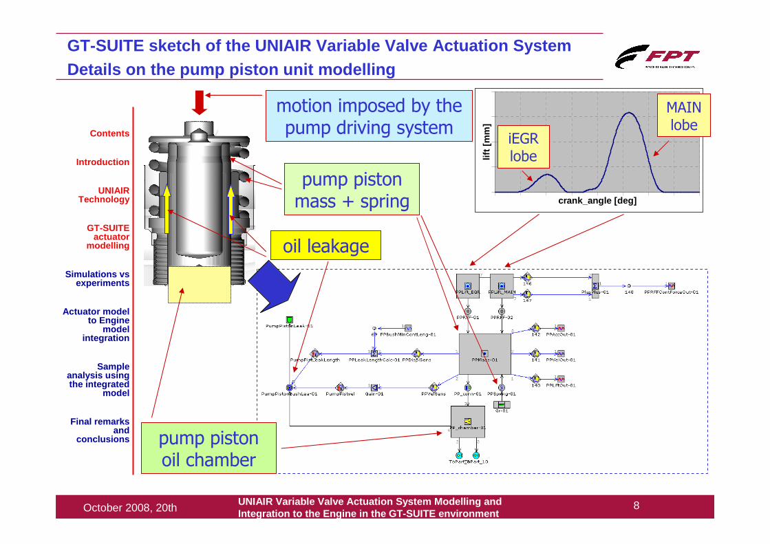
GT-SUITE sketch of the UNIAIR Variable Valve Actuat ion SystemDetails on the pump piston unit modelling
motion imposed by the pump driving system
pump piston mass + spring
oil leakage
pump piston oil chamber
crank_angle [deg]
lift [
mm
]
iEGRlobe
MAIN lobe
Contents
Introduction
UNIAIR Technology
GT-SUITE actuator
modelling
Simulations vsexperiments
Actuator model to Engine
model integration
Sample analysis using the integrated
model
Final remarks and
conclusions
UNIAIR Variable Valve Actuation System Modelling andIntegration to the Engine in the GT -SUITE environment
9October 2008, 20th
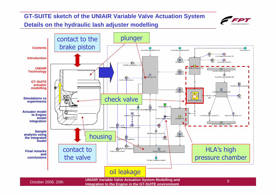
GT-SUITE sketch of the UNIAIR Variable Valve Actuat ion SystemDetails on the hydraulic lash adjuster modelling
contact to the brake piston
contact to the valve
plunger
housing
oil leakage
check valve
HLA’s high pressure chamber
Contents
Introduction
UNIAIR Technology
GT-SUITE actuator
modelling
Simulations vsexperiments
Actuator model to Engine
model integration
Sample analysis using the integrated
model
Final remarks and
conclusions
UNIAIR Variable Valve Actuation System Modelling andIntegration to the Engine in the GT -SUITE environment
10October 2008, 20th
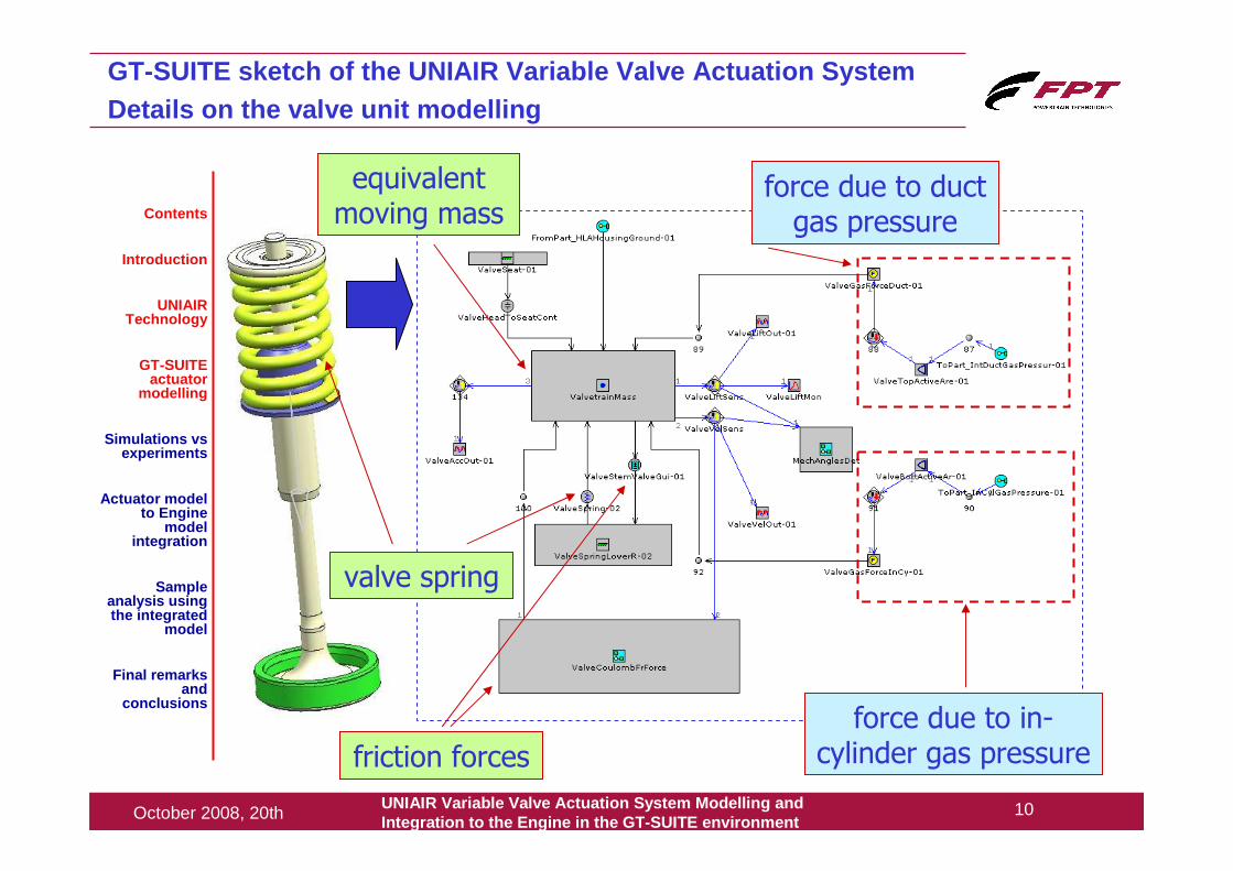
GT-SUITE sketch of the UNIAIR Variable Valve Actuat ion SystemDetails on the valve unit modelling
valve spring
equivalent moving mass
force due to duct gas pressure
force due to in-cylinder gas pressurefriction forces
Contents
Introduction
UNIAIR Technology
GT-SUITE actuator
modelling
Simulations vsexperiments
Actuator model to Engine
model integration
Sample analysis using the integrated
model
Final remarks and
conclusions
UNIAIR Variable Valve Actuation System Modelling andIntegration to the Engine in the GT -SUITE environment
11October 2008, 20th
GT-SUITE sketch of the UNIAIR Variable Valve Actuat ion SystemGeneral notes
Contents
Introduction
UNIAIR Technology
GT-SUITE actuator
modelling
Simulations vsexperiments
Actuator model to Engine
model integration
Sample analysis using the integrated
model
Final remarks and
conclusions
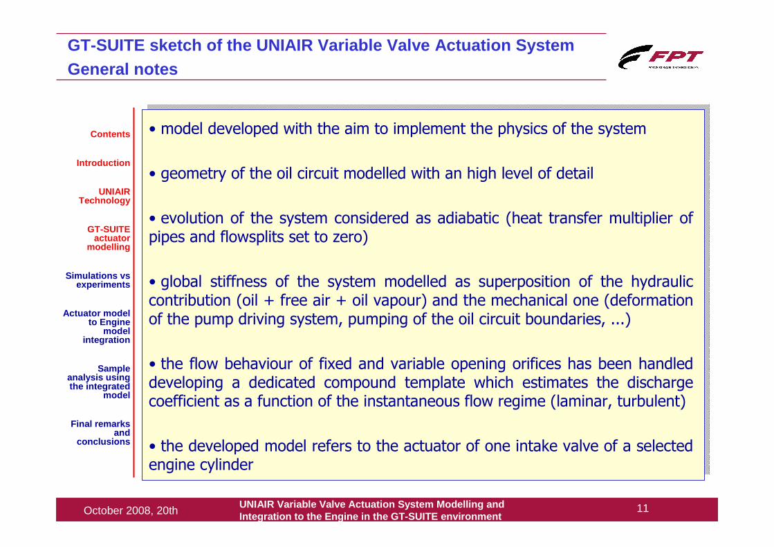
• model developed with the aim to implement the physics of the system
• geometry of the oil circuit modelled with an high level of detail
• evolution of the system considered as adiabatic (heat transfer multiplier of pipes and flowsplits set to zero)
• global stiffness of the system modelled as superposition of the hydraulic contribution (oil + free air + oil vapour) and the mechanical one (deformation of the pump driving system, pumping of the oil circuit boundaries, ...)
• the flow behaviour of fixed and variable opening orifices has been handled developing a dedicated compound template which estimates the discharge coefficient as a function of the instantaneous flow regime (laminar, turbulent)
• the developed model refers to the actuator of one intake valve of a selected engine cylinder
UNIAIR Variable Valve Actuation System Modelling andIntegration to the Engine in the GT -SUITE environment
12October 2008, 20th
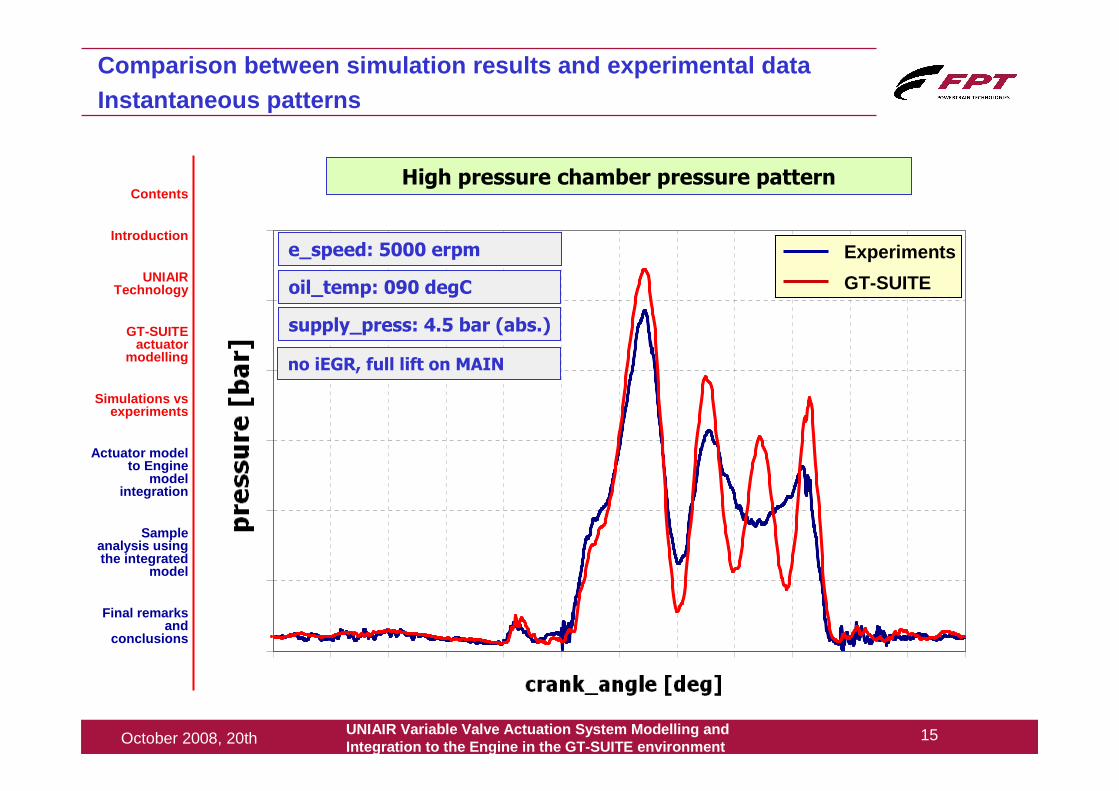
Comparison between simulation results and experimental d ata
• the comparison between simulation results and experimental data acquired at the motored test bench is shown in the following slides in two forms:
• instantaneous patterns of valve lift and oil pressure in the high pressure chamber
• actuator characteristic maps (valve opening and closing angles plotted against the solenoid valve electrical control angle Φ1 or Φ2)
• hot oil temperature and different engine speeds and valve controls are considered
• the parameters set of the model comes from a preliminary identification
Contents
Introduction
UNIAIR Technology
GT-SUITE actuator
modelling
Simulations vsexperiments
Actuator model to Engine
model integration
Sample analysis using the integrated
model
Final remarks and
conclusions
UNIAIR Variable Valve Actuation System Modelling andIntegration to the Engine in the GT -SUITE environment
13October 2008, 20th
crank_angle [deg]
pressure [bar]
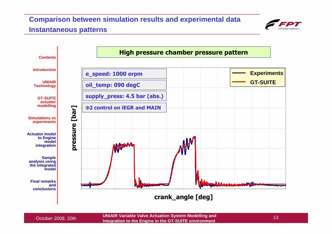
High pressure chamber pressure pattern
Comparison between simulation results and experimental d ataInstantaneous patterns
Contents
Introduction
UNIAIR Technology
GT-SUITE actuator
modelling
Simulations vsexperiments
Actuator model to Engine
model integration
Sample analysis using the integrated
model
Final remarks and
conclusions
e_speed: 1000 erpm
oil_temp: 090 degC
supply_press: 4.5 bar (abs.)
ΦΦΦΦ2 control on iEGR and MAIN
Experiments
GT-SUITE
UNIAIR Variable Valve Actuation System Modelling andIntegration to the Engine in the GT -SUITE environment
14October 2008, 20th
crank_angle [deg]
valve lift [m
m]
Comparison between simulation results and experimental d ataInstantaneous patterns
Contents
Introduction
UNIAIR Technology
GT-SUITE actuator
modelling
Simulations vsexperiments
Actuator model to Engine
model integration
Sample analysis using the integrated
model
Final remarks and
conclusions
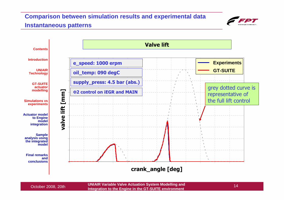
Experiments
GT-SUITE
grey dotted curve is representative of the full lift control
Valve lift
e_speed: 1000 erpm
oil_temp: 090 degC
supply_press: 4.5 bar (abs.)
ΦΦΦΦ2 control on iEGR and MAIN
UNIAIR Variable Valve Actuation System Modelling andIntegration to the Engine in the GT -SUITE environment
15October 2008, 20th
crank_angle [deg]
pres
sure
[bar
]
Comparison between simulation results and experimental d ataInstantaneous patterns
Contents
Introduction
UNIAIR Technology
GT-SUITE actuator
modelling
Simulations vsexperiments
Actuator model to Engine
model integration
Sample analysis using the integrated
model
Final remarks and
conclusions
Experiments
GT-SUITE
High pressure chamber pressure pattern
e_speed: 5000 erpm
oil_temp: 090 degC
supply_press: 4.5 bar (abs.)
no iEGR, full lift on MAIN
UNIAIR Variable Valve Actuation System Modelling andIntegration to the Engine in the GT -SUITE environment
16October 2008, 20th
crank_angle [deg]
lift [
mm
]
Comparison between simulation results and experimental d ataInstantaneous patterns
Contents
Introduction
UNIAIR Technology
GT-SUITE actuator
modelling
Simulations vsexperiments
Actuator model to Engine
model integration
Sample analysis using the integrated
model
Final remarks and
conclusions
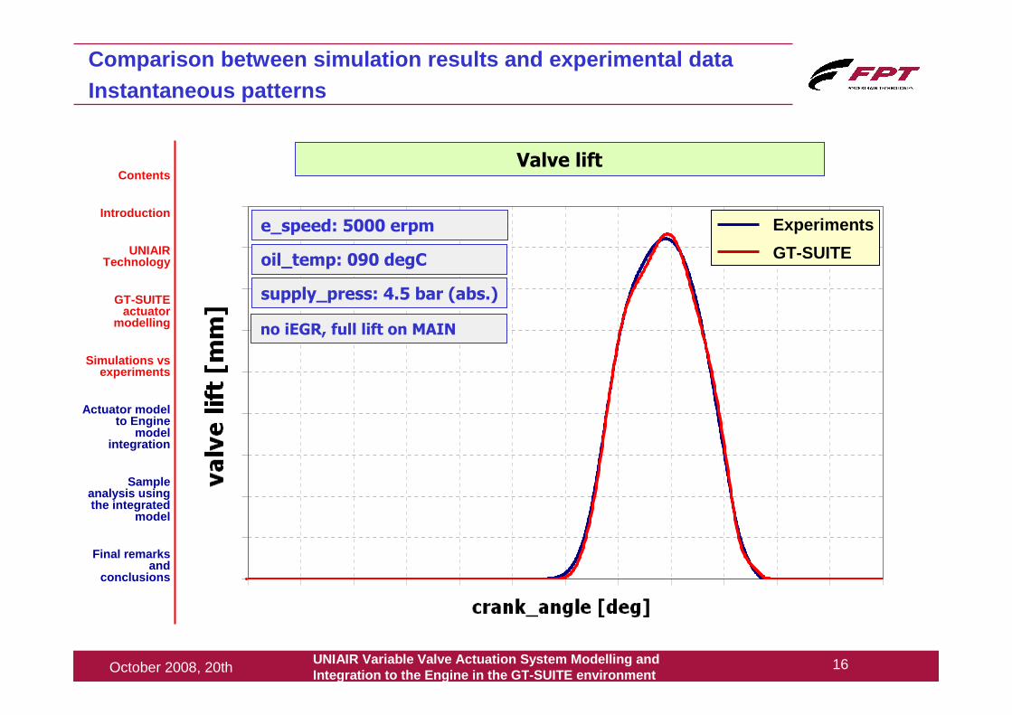
Valve lift
Experiments
GT-SUITE
e_speed: 5000 erpm
oil_temp: 090 degC
supply_press: 4.5 bar (abs.)
no iEGR, full lift on MAIN
UNIAIR Variable Valve Actuation System Modelling andIntegration to the Engine in the GT -SUITE environment
17October 2008, 20th
crank_angle [deg]
pres
sure
[bar
]
Comparison between simulation results and experimental d ataInstantaneous patterns
Contents
Introduction
UNIAIR Technology
GT-SUITE actuator
modelling
Simulations vsexperiments
Actuator model to Engine
model integration
Sample analysis using the integrated
model
Final remarks and
conclusions
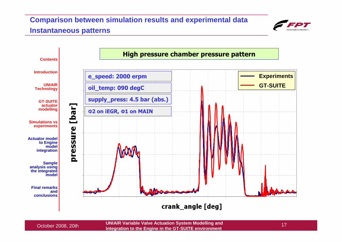
High pressure chamber pressure pattern
Experiments
GT-SUITE
e_speed: 2000 erpm
oil_temp: 090 degC
supply_press: 4.5 bar (abs.)
ΦΦΦΦ2 on iEGR, ΦΦΦΦ1 on MAIN
UNIAIR Variable Valve Actuation System Modelling andIntegration to the Engine in the GT -SUITE environment
18October 2008, 20th
crank_angle [deg]
valv
e lif
t [m
m]
Comparison between simulation results and experimental d ataInstantaneous patterns
Contents
Introduction
UNIAIR Technology
GT-SUITE actuator
modelling
Simulations vsexperiments
Actuator model to Engine
model integration
Sample analysis using the integrated
model
Final remarks and
conclusions
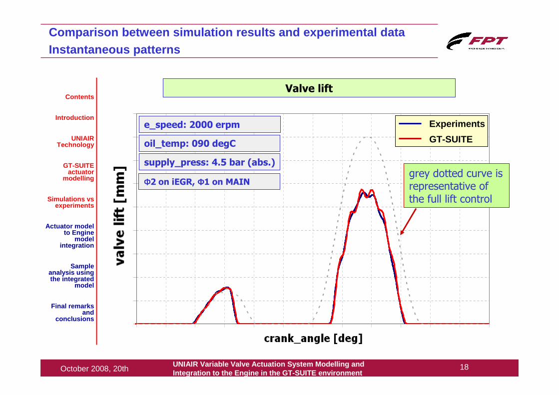
Valve lift
Experiments
GT-SUITE
grey dotted curve is representative of the full lift control
e_speed: 2000 erpm
oil_temp: 090 degC
supply_press: 4.5 bar (abs.)
ΦΦΦΦ2 on iEGR, ΦΦΦΦ1 on MAIN
UNIAIR Variable Valve Actuation System Modelling andIntegration to the Engine in the GT -SUITE environment
19October 2008, 20th
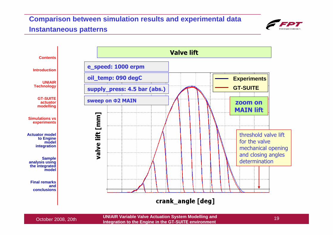
Comparison between simulation results and experimental d ataInstantaneous patterns
Contents
Introduction
UNIAIR Technology
GT-SUITE actuator
modelling
Simulations vsexperiments
Actuator model to Engine
model integration
Sample analysis using the integrated
model
Final remarks and
conclusions
Experiments
GT-SUITE
Valve lift
zoom on MAIN lift
threshold valve lift for the valve mechanical opening and closing angles determination
e_speed: 1000 erpm
oil_temp: 090 degC
supply_press: 4.5 bar (abs.)
sweep on ΦΦΦΦ2 MAIN
UNIAIR Variable Valve Actuation System Modelling andIntegration to the Engine in the GT -SUITE environment
20October 2008, 20th
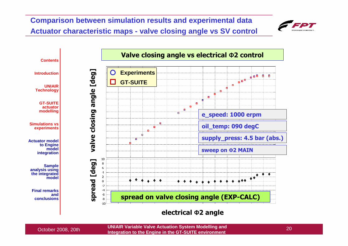
Comparison between simulation results and experimental d ataActuator characteristic maps - valve closing angle vs SV control
Contents
Introduction
UNIAIR Technology
GT-SUITE actuator
modelling
Simulations vsexperiments
Actuator model to Engine
model integration
Sample analysis using the integrated
model
Final remarks and
conclusions
Valve closing angle vs electrical ΦΦΦΦ2 control
valve closing angle [deg]
electrical ΦΦΦΦ2 angle
Experiments
GT-SUITE
spread [deg]
spread on valve closing angle (EXP-CALC)
e_speed: 1000 erpm
oil_temp: 090 degC
supply_press: 4.5 bar (abs.)
sweep on ΦΦΦΦ2 MAIN
UNIAIR Variable Valve Actuation System Modelling andIntegration to the Engine in the GT -SUITE environment
21October 2008, 20th
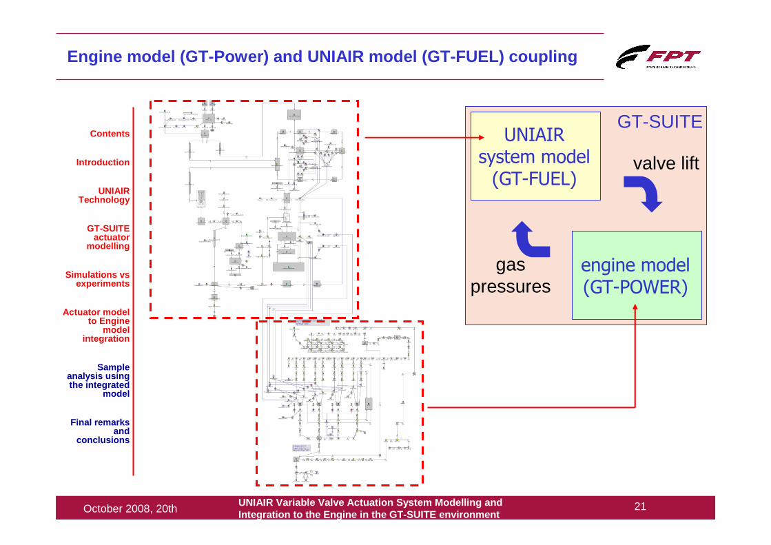
UNIAIR system model (GT-FUEL)
engine model (GT-POWER)
GT-SUITE
valve lift
gas pressures
Engine model (GT-Power) and UNIAIR model (GT-FUEL) c oupling
Contents
Introduction
UNIAIR Technology
GT-SUITE actuator
modelling
Simulations vsexperiments
Actuator model to Engine
model integration
Sample analysis using the integrated
model
Final remarks and
conclusions
UNIAIR Variable Valve Actuation System Modelling andIntegration to the Engine in the GT -SUITE environment
22October 2008, 20th
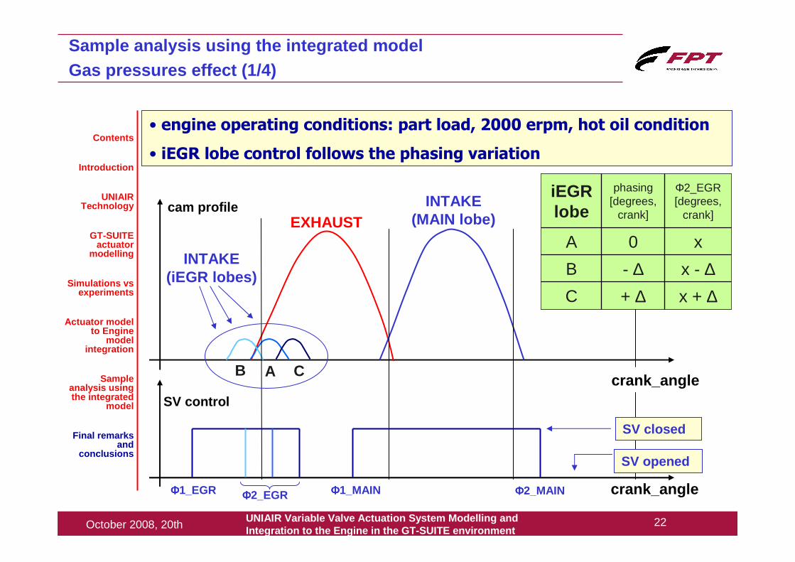
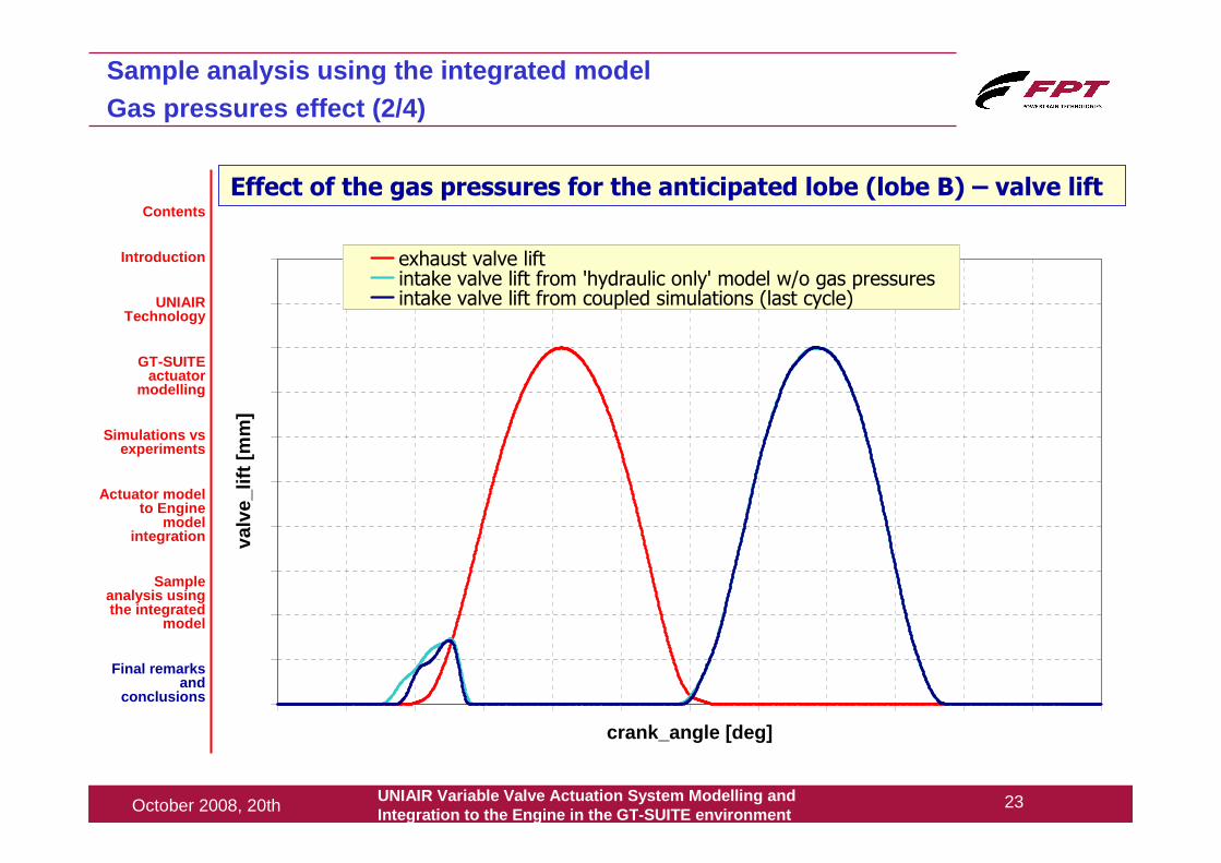
Sample analysis using the integrated modelGas pressures effect (1/4)
• engine operating conditions: part load, 2000 erpm, hot oil condition
• iEGR lobe control follows the phasing variation
crank_angle
cam profile INTAKE (MAIN lobe)EXHAUST
INTAKE (iEGR lobes)
crank_angle
SV control
SV closed
SV opened
ΦΦΦΦ1_EGR ΦΦΦΦ2_EGR ΦΦΦΦ1_MAIN ΦΦΦΦ2_MAIN
+ ∆- ∆0
phasing[degrees,
crank]
x + ∆x - ∆
x
Φ2_EGR [degrees,
crank]
C
B
A
iEGRlobe
A CB
Contents
Introduction
UNIAIR Technology
GT-SUITE actuator
modelling
Simulations vsexperiments
Actuator model to Engine
model integration
Sample analysis using the integrated
model
Final remarks and
conclusions
UNIAIR Variable Valve Actuation System Modelling andIntegration to the Engine in the GT -SUITE environment
23October 2008, 20th
crank_angle [deg]
valv
e_lif
t [m
m]
exhaust valve liftintake valve lift from 'hydraulic only' model w/o gas pressuresintake valve lift from coupled simulations (last cycle)
Effect of the gas pressures for the anticipated lobe (lobe B) – valve lift
Sample analysis using the integrated modelGas pressures effect (2/4)
Contents
Introduction
UNIAIR Technology
GT-SUITE actuator
modelling
Simulations vsexperiments
Actuator model to Engine
model integration
Sample analysis using the integrated
model
Final remarks and
conclusions
UNIAIR Variable Valve Actuation System Modelling andIntegration to the Engine in the GT -SUITE environment
24October 2008, 20th
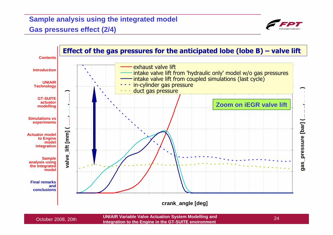
Effect of the gas pressures for the anticipated lobe (lobe B) – valve lift
Sample analysis using the integrated modelGas pressures effect (2/4)
Contents
Introduction
UNIAIR Technology
GT-SUITE actuator
modelling
Simulations vsexperiments
Actuator model to Engine
model integration
Sample analysis using the integrated
model
Final remarks and
conclusions
crank_angle [deg]
valv
e_lif
t [m
m] (
__
_, _
__, _
__ )
gas_
pres
sure
[bar
] (
_ _
_, _
_ _
)
exhaust valve liftintake valve lift from 'hydraulic only' model w/o gas pressuresintake valve lift from coupled simulations (last cycle)in-cylinder gas pressureduct gas pressure
Zoom on iEGR valve lift
UNIAIR Variable Valve Actuation System Modelling andIntegration to the Engine in the GT -SUITE environment
25October 2008, 20th
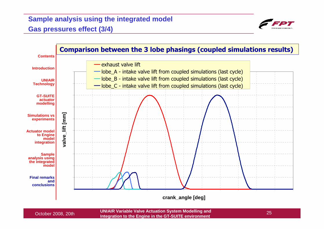
Sample analysis using the integrated modelGas pressures effect (3/4)
Comparison between the 3 lobe phasings (coupled simulations results)Contents
Introduction
UNIAIR Technology
GT-SUITE actuator
modelling
Simulations vsexperiments
Actuator model to Engine
model integration
Sample analysis using the integrated
model
Final remarks and
conclusions
crank_angle [deg]
valv
e_lif
t [m
m]
exhaust valve lift
lobe_A - intake valve lift from coupled simulations (last cycle)
lobe_B - intake valve lift from coupled simulations (last cycle)
lobe_C - intake valve lift from coupled simulations (last cycle)
UNIAIR Variable Valve Actuation System Modelling andIntegration to the Engine in the GT -SUITE environment
26October 2008, 20th
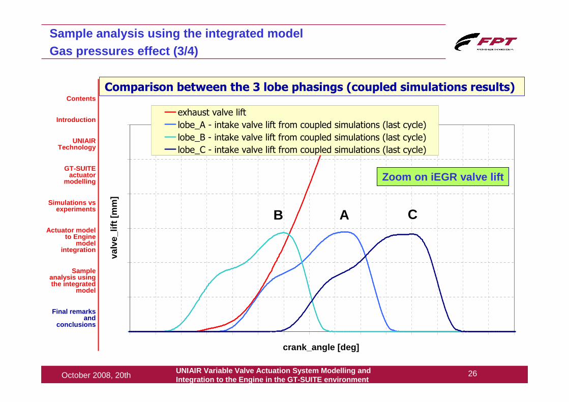
Sample analysis using the integrated modelGas pressures effect (3/4)
Comparison between the 3 lobe phasings (coupled simulations results)Contents
Introduction
UNIAIR Technology
GT-SUITE actuator
modelling
Simulations vsexperiments
Actuator model to Engine
model integration
Sample analysis using the integrated
model
Final remarks and
conclusions
crank_angle [deg]
valv
e_lif
t [m
m]
exhaust valve lift
lobe_A - intake valve lift from coupled simulations (last cycle)
lobe_B - intake valve lift from coupled simulations (last cycle)
lobe_C - intake valve lift from coupled simulations (last cycle)
Zoom on iEGR valve lift
B A C
UNIAIR Variable Valve Actuation System Modelling andIntegration to the Engine in the GT -SUITE environment
27October 2008, 20th
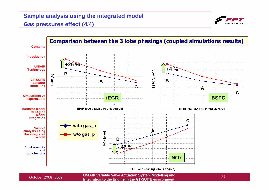
Comparison between the 3 lobe phasings (coupled simulations results)
Sample analysis using the integrated modelGas pressures effect (4/4)
iEGR BSFC
NOx
+26 %+4 %
- 47 %
Contents
Introduction
UNIAIR Technology
GT-SUITE actuator
modelling
Simulations vsexperiments
Actuator model to Engine
model integration
Sample analysis using the integrated
model
Final remarks and
conclusions
AC
B
AC
B
B
A
Cwith gas_p
w/o gas_p
UNIAIR Variable Valve Actuation System Modelling andIntegration to the Engine in the GT -SUITE environment
28October 2008, 20th
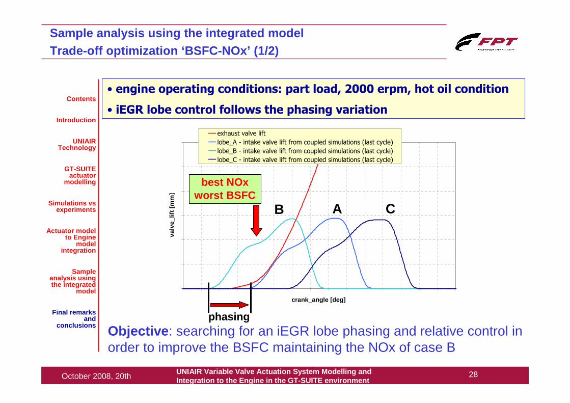
crank_angle [deg]
valv
e_lif
t [m
m]
exhaust valve lift
lobe_A - intake valve lift from coupled simulations (last cycle)
lobe_B - intake valve lift from coupled simulations (last cycle)
lobe_C - intake valve lift from coupled simulations (last cycle)
best NOxworst BSFC
B A C
Sample analysis using the integrated modelTrade-off optimization ‘BSFC-NOx’ (1/2)
Objective : searching for an iEGR lobe phasing and relative control in order to improve the BSFC maintaining the NOx of case B
• engine operating conditions: part load, 2000 erpm, hot oil condition
• iEGR lobe control follows the phasing variationContents
Introduction
UNIAIR Technology
GT-SUITE actuator
modelling
Simulations vsexperiments
Actuator model to Engine
model integration
Sample analysis using the integrated
model
Final remarks and
conclusions phasing
UNIAIR Variable Valve Actuation System Modelling andIntegration to the Engine in the GT -SUITE environment
29October 2008, 20th
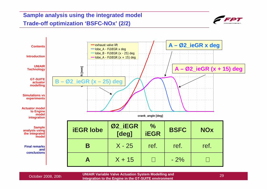
crank_angle [deg]
valv
e_lif
t [m
m]
exhaust valve lift
lobe_A - Fi2iEGR x deg
lobe_B - Fi2iEGR (x - 25) deg
lobe_A - Fi2iEGR (x + 15) deg
X + 15
X - 25
Ø2_iEGR [deg]
≅- 2%≅A
ref.ref.ref.B
NOxBSFC%
iEGRiEGR lobe
Sample analysis using the integrated modelTrade-off optimization ‘BSFC-NOx’ (2/2)
A – Ø2_ieGR (x + 15) deg
A – Ø2_ieGR x deg
B – Ø2_ieGR (x – 25) deg
Contents
Introduction
UNIAIR Technology
GT-SUITE actuator
modelling
Simulations vsexperiments
Actuator model to Engine
model integration
Sample analysis using the integrated
model
Final remarks and
conclusions
UNIAIR Variable Valve Actuation System Modelling andIntegration to the Engine in the GT -SUITE environment
30October 2008, 20th
Final remarks and conclusions (1/2)
Contents
Introduction
UNIAIR Technology
GT-SUITE actuator
modelling
Simulations vsexperiments
Actuator model to Engine
model integration
Sample analysis using the integrated
model
Final remarks and
conclusions
• a detailed model of the UNIAIR variable valve actuation system has been developed in the GT-SUITE environment
• the elaborated model shows a level of accuracy in the description of the real behaviour of the actuator which is generally good over the whole actuator operating range
• the model of the actuator (hydro-mechanical domain) has been integrated to the model of the engine (thermo-fluid dynamic domain) with the aim to perform integrated simulations in which the valve lift generated by the hydraulic network takes into account, speed by speed and load by load, the effect of the gas pressures
• the developed tool will allow to perform engine analyses focused on the optimization of additional cam lobes (internal EGR, engine braking)
UNIAIR Variable Valve Actuation System Modelling andIntegration to the Engine in the GT -SUITE environment
31October 2008, 20th
Final remarks and conclusions (2/2)
Contents
Introduction
UNIAIR Technology
GT-SUITE actuator
modelling
Simulations vsexperiments
Actuator model to Engine
model integration
Sample analysis using the integrated
model
Final remarks and
conclusions
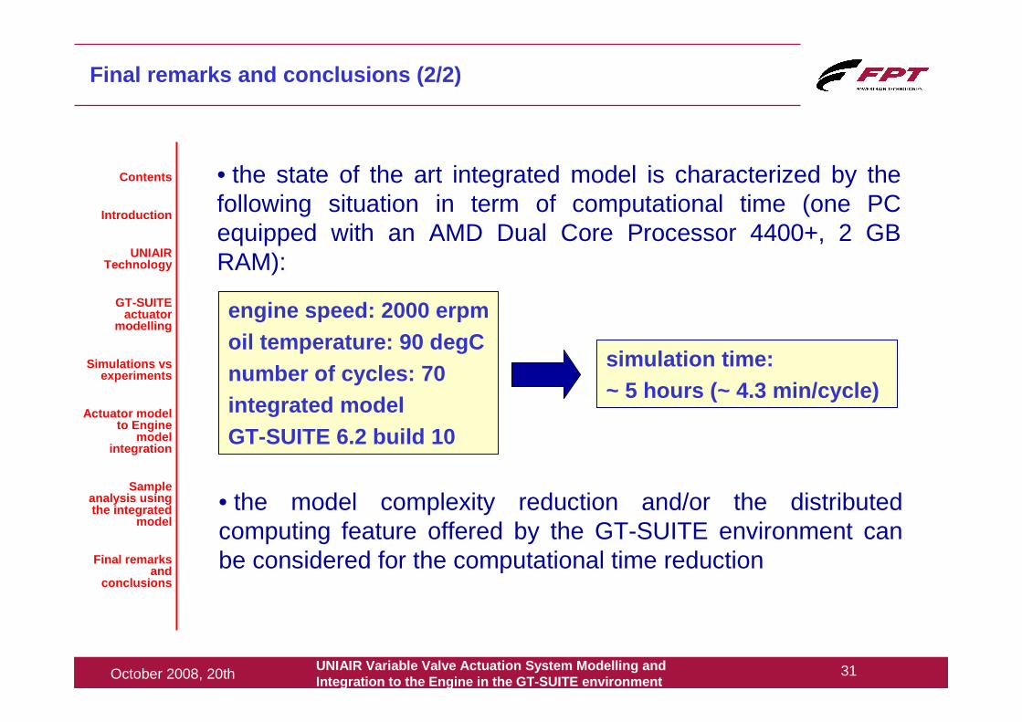
• the state of the art integrated model is characterized by the following situation in term of computational time (one PC equipped with an AMD Dual Core Processor 4400+, 2 GB RAM):
engine speed: 2000 erpmoil temperature: 90 degCnumber of cycles: 70integrated modelGT-SUITE 6.2 build 10
simulation time:~ 5 hours (~ 4.3 min/cycle)
• the model complexity reduction and/or the distributedcomputing feature offered by the GT-SUITE environment can be considered for the computational time reduction

UNIAIR Variable Valve Actuation System Modelling andIntegration to the Engine in the GT -SUITE environment
32October 2008, 20th
Contents
Introduction
UNIAIR Technology
GT-SUITE actuator
modelling
Simulations vsexperiments
Actuator model to Engine
model integration
Sample analysis using the integrated
model
Final remarks and
conclusions
Questions ?Questions ?
... thank you for your attentionthank you for your attention
Thanks to Gamma Technologies and in particular to Shawn Harnish for the
excellent support and ...


![Progress in Camless Variable Valve Actuation with Two ... Articles/Progress in camless variable...camless technologies in emission reduction as well as fuel economy [17]. A family](https://img.dokumen.tips/doc/110x75/5aa889937f8b9a6c188bb001/progress-in-camless-variable-valve-actuation-with-two-articlesprogress-in-camless.jpg)