Embed Size (px)
Citation preview

Design & ConstructionDesign & Constructionof Offshore Structures
Hard Rock Hotel, Singapore13th to 15th June 201113th to 15th June 2011
Dr Paul FriezePAFA Consulting Engineers, UK
Questions and comments may be addressed to: pafrieze@pafa co [email protected]

Course Agendag
Introduction to PAFA Consulting Engineersg g
Session 1 – Introduction to Offshore Structures & Standards
Session 2 – Metocean, Wave Loading and Buoyancy
G h P l d l lSession 3 – Geotechnics, Piles and Structural Analysis
Session 4 – Detailed Design and Specialized Analysisg p y
Session 5 – Structural Integrity, Repair, Risk and Reliability

Session 2
Off h i I i i• Offshore Site Investigations
• Meteorological & Oceanographical Data
• Wave Theories
• Computational Hydrodynamics• Computational Hydrodynamics
• Wind & Wave Forces
• Buoyancy and Stability

Offshore Site InvestigationsInvestigations normally required:
g
i) Meteorological and oceanographical (metocean) surveysg g p y
ii) Site and seabed surveys
iii) Soil investigationsiii) Soil investigations
iv) Seismic hazard surveys
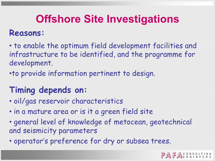
Offshore Site InvestigationsReasons:• to enable the optimum field development facilities and
g
• to enable the optimum field development facilities and infrastructure to be identified, and the programme for development.•to provide information pertinent to design.
Timing depends on:Timing depends on:• oil/gas reservoir characteristics• in a mature area or is it a green field siteg• general level of knowledge of metocean, geotechnical and seismicity parameters
’ f f d b • operator’s preference for dry or subsea trees.

Offshore Site InvestigationsFactors impacting on choice:• water depth
g
• water depth• general level of extreme wave heights• the presence of regular or irregular strong currentsthe presence of regular or rregular strong currents• seabed stability• presence of shallow gas, faults or seismicity.
Executed by:• meteorologists and oceanographers• meteorologists and oceanographers• geologists and seismologists.

Metocean Surveys• Water Depth, Tides and Storm Surges
y
• Wind
• Waves
• Current
• Marine Growth
• Tsunamis
• Sea Ice and IcebergsSea Ice and Icebergs
• Ice and Snow Accretion

Metocean SurveysGeneral considerations
d h
y
Metocean data to be appropriate to the region.Describe by physical characteristics.If available describe statistically using joint parametersIf available, describe statistically using joint parametersAccounting for:• type of structure being designed;type of structure being designed;• phase of development (e.g. construction, transportation, installation, drilling, production, etc.);• limit state considered.

Metocean SurveysWind
d d d d ll d ll
y
Wind speed and direction vary spatially and temporally.Data normally insufficient to correctly describe variations.Design parameters simplified to statistical definitions for Design parameters simplified to statistical definitions for length and time scales.On length scales for large offshore structures, averaged g g , gdurations over one hour do not vary significantly horizontally but change with elevation - wind profile.O sh t tim s l s hi h s ds d m s ti l On shorter time scales, higher speeds and more spatial variation.Thus, wind speed defined by averaging time interval and hus, w n sp f n y a rag ng t m nt r a an elevation.
Metocean SurveysWind
d l f f
y
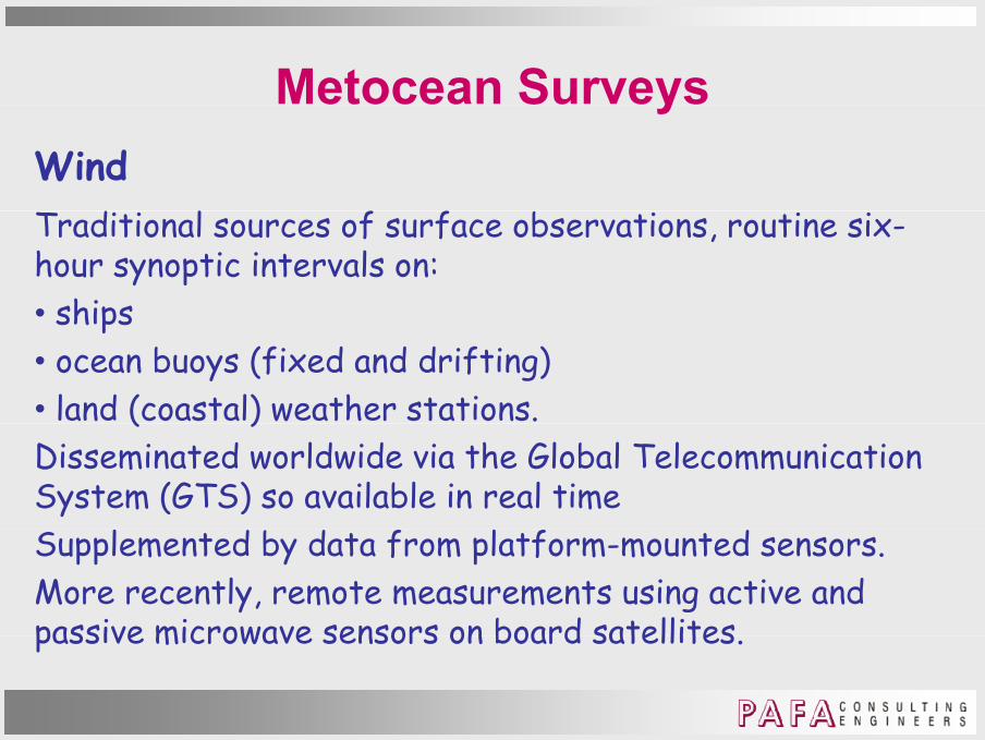
Traditional sources of surface observations, routine six-hour synoptic intervals on:• shipsships• ocean buoys (fixed and drifting) • land (coastal) weather stations. ( )Disseminated worldwide via the Global Telecommunication System (GTS) so available in real timeSupplemented by data from platform-mounted sensors.More recently, remote measurements using active and passive microwave sensors on board satellitespassive microwave sensors on board satellites.

Metocean SurveysWind
d d
y
Speed – measured using:• cup anemometers• hot wire anemometers• hot-wire anemometers• laser Doppler anemometers• sonic anemometers – measure x y z but need calibrationsonic anemometers measure x, y, z but need calibration• windmill (propeller) anemometers – must weather vane.

Metocean SurveysWind
d
y
Direction – measured by• weather vane
Speed & Direction – measured bySpeed & Direction measured by• aerovane

Metocean SurveysWind
l h
y
General Requirements – when measuring:• know height above MSL • clear of disturbances e g flow from wave surface or • clear of disturbances, e.g. flow from wave surface or structure• know averaging time of the wind speed measurementg g p• measure air & sea temperatures to evaluate atmospheric stability – affects profile/wind spectrum in low winds• the anemometer should not be aerodynamically shielded• correct measurements over land to reflect over water conditionsconditions.

Metocean SurveysWater Depth
y
Measurements:• initial estimates from Admiralty
and similar charts and similar charts • float-stilling well water level gauge
•submerged pressure transducers but need long narrow tube to achieve high frequency damping
i ON R ( d N i i d R i )•acoustics or SONAR (Sound Navigation and Ranging).

Metocean SurveysCurrent
d d
y
Speed & Direction – measured using:• pilot charts for initial estimates of surface values• propeller and rotor current meters • propeller and rotor current meters • electromagnetic current meters – small & robust, work well in splash zone - handle air-water interface p• ultrasonic meters - piezoelectric transducers - both transmit/receive - do not handle air-water interface.

Metocean SurveysCurrent
d d
y
Speed & Direction – measured using:• ADCP (Acoustic Doppler Current Profiler) – measures currents with sound using Doppler effectcurrents with sound using Doppler effect

Metocean SurveysADCP
h d h f f
y
ADCPs are now the dominant choice for performing current measurements because of their convenience in application, long profiling range (tens to several hundred metres g p f g g ( u mdepending on their operational frequency) and proven accuracy. Th l b d t h i ht d They can also be used to measure wave heights and directions as discussed below. When deployed on a platform, the rapidly diverging acoustic beam can be p p y g gintercepted by the platform’s components which leads to a bias in the current velocity estimates. Careful orientation of ADCPs in such circumstances can minimise the impact of of ADCPs in such circumstances can minimise the impact of this interference.

Metocean SurveysCurrent measurements – Satellites & radar systems
ll d d d l h
y
Satellites and radar-based systems now supplement much current data particularly if recorded around platforms because the presence of the platform modifies the u p f p f m m fcurrent.Because of the relative importance of these now, some are
i d i th t f lidreviewed in the next few slides.

Metocean SurveysCurrent measurements – Satellites & radar systems
y
Satellite systems have been available for nearly 3 decades. A range of sensors allows either direct or indirect estimation of current speed and direction estimation of current speed and direction. Via measurement of one or more sea surface parameters such as temperature or height. Current variation with depth cannot be measured directly, under certain conditions (e.g., absence of seabed friction, coastal effects and mixed water layers) surface current coastal effects and mixed water layers) surface current gives a reasonable indication of bulk current flow.
Metocean SurveysCurrent measurements – Satellites & radar systems
y
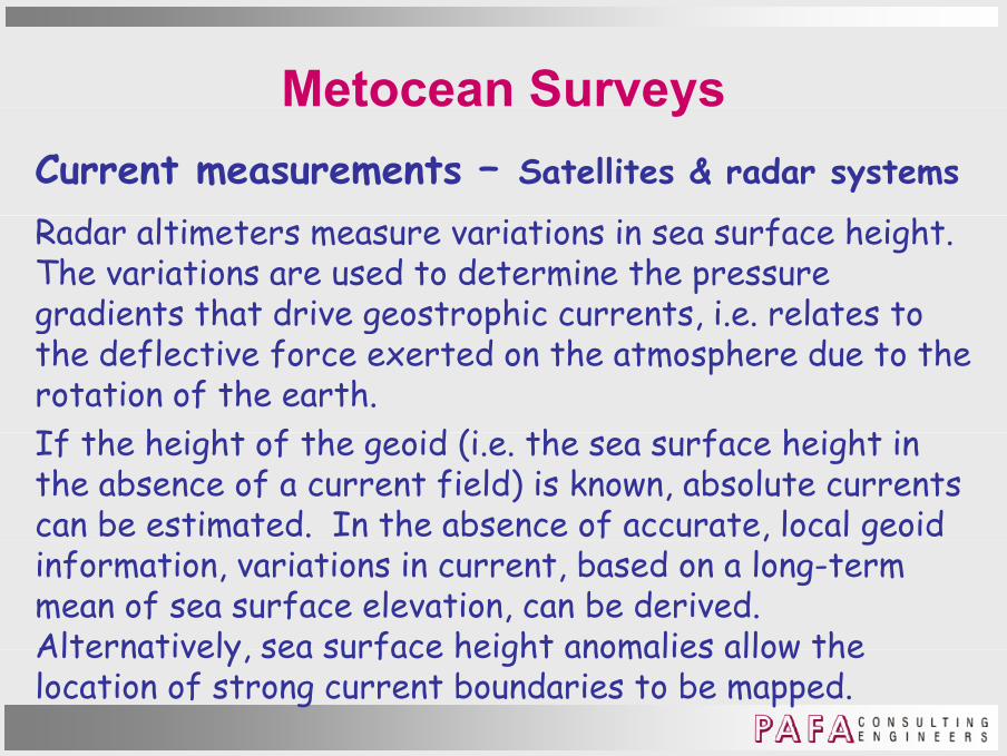
Radar altimeters measure variations in sea surface height. The variations are used to determine the pressure gradients that drive geostrophic currents, i.e. relates to gradients that drive geostrophic currents, i.e. relates to the deflective force exerted on the atmosphere due to the rotation of the earth. If th h i ht f th id (i th f h i ht i If the height of the geoid (i.e. the sea surface height in the absence of a current field) is known, absolute currents can be estimated. In the absence of accurate, local geoid, ginformation, variations in current, based on a long-term mean of sea surface elevation, can be derived. Alternatively sea surface height anomalies allow the Alternatively, sea surface height anomalies allow the location of strong current boundaries to be mapped.

Metocean SurveysCurrent measurements – Satellites & radar systems
y
An advancement on basic radar altimetry is Synthetic Aperture Radar (SAR) which provides a high resolution image of the sea surface (and potentially the direct image of the sea surface (and potentially the direct measurement of currents). A SAR image is formed by combining a number of radar images taken along the flight path of the satellite thus effectively increasing the path of the satellite, thus effectively increasing the aperture width of the radar and hence its resolution capability.Altimeters operating at optical frequencies (lidars) represent an alternative to radar altimeters; however, they have safety and operational limitations (cloud cover) they have safety and operational limitations (cloud cover) that need to be considered.

Metocean SurveysCurrent measurements –
y
Satellites & radar
systemsSAR has been extended to measurement of wind fields but wind speed estimates may but wind speed estimates may not reliable for near-shore locations.

Metocean SurveysCurrent measurements – Satellites & radar systems
y
In addition to these active sensors, passive sensors are also used to indirectly estimate current velocity. Radiometers record the time evolution of sea surface Radiometers record the time evolution of sea surface temperature. Progressive thermal images allow current features to be tracked (either manually or automated approaches) and associated current velocities estimated approaches) and associated current velocities estimated. Good correlation with in-situ measurements can be achieved although the method works better where a relatively high variability in surface temperature exists. Cloud cover limits applicability. By combining sea surface temperature data and altimetry data, spatial coverage can temperature data and alt metry data, spat al coverage can be improved and current features better resolved.

Metocean SurveysCurrent measurements – Satellites & radar systems
y
Due account needs to be taken of differences in the spatial and temporal extent of satellite-based measurement in comparison with in-situ measurements.measurement in comparison with in situ measurements.High frequency (HF) radars, such as the direction finding CODAR system, can produce surface current vector maps
l l d ti ti l l I t i on local and synoptic spatial scales. Inter-comparison studies of HF radars show good agreement with ADCP estimates. At least two spatially separate radar stations p y p(tens of kilometres) are required to produce a 2-D vector map, which has limited widespread application on solitary platformsplatforms.

Metocean SurveysCurrent measurements – Satellites & radar systems
y
Frequently, a cross-sectional profile or transect (transverse section) survey is required to properly characterise the threat of a local current to a critical characterise the threat of a local current to a critical deepwater operation, such as a heavy lift. Such data can be generated by integrating an ADCP into a towfish. Autonomous Underwater Vehicles (ROVs) when outfitted Autonomous Underwater Vehicles (ROVs), when outfitted with an ADCP (plus other instruments), can typically out-manoeuvre towfish, survey at higher speeds, and reach full ocean depths.

Metocean SurveysWater surface spectrum
y
Diagrammatic illustration of water surface spectrum

Metocean SurveysWaves
d d h fl
y
Most waves are generated by wind – three influences:- Wind speed
Duration- Duration- Fetch – length of open water over which wind has blown.
These work together to determine size and shape of waves. The greater the variable, the larger the waves.But theoretical limits for each variable; the smaller the But, theoretical limits for each variable; the smaller the fetch, the smaller will be the largest wave for a given wind speed, regardless of duration.

Metocean SurveysWaves
h d l h
y
Three wave types develop with time:
Ripples (capillary waves)- Ripples (capillary waves)- Seas - SwellsSwells.
Ripples appear on smooth water in light wind, but die if pp pp g ,the wind stops.

Metocean SurveysWaves
( d ) d h h d h l
y
Seas (or wind seas) are created when the wind has blown for a while at a given velocity. They tend to last much longer, even after the wind has died. g , f w .Swells are waves that have moved away from their area of origin and are unrelated to the local wind conditions. They
b th ht f th t i t l ft th i d may be thought of as seas that persist long after the wind that produced them has stopped.

Metocean SurveysWaves - Measurements
f
y
At Surface• Staff gauges
a vertical staff (pole)– a vertical staff (pole)– rigidly mounted so no interference with water motion- electronically records water surface by changes in electronically records water surface by changes in resistance, capacitance or inductance- affected by marine fouling, ice, floating objects, human tampering and lightening.

Metocean SurveysWaves - Measurements
f
y
At Surface• Photo-pole gauge
photographs surface elevation - photographs surface elevation - cheaper to maintain but data interpretation more expensive.p
• Wave buoys- measures time-dependent vertical acceleration- integrate the data twice, to obtain time-dependent surface elevation, from which wave height can be ascertained ascertained.

Metocean SurveysWaves – Measurements
l f
y
Below Surface• Pressure gauges
placed relatively close to surface to measure variation – placed relatively close to surface to measure variation in the dynamic wave pressure- avoid surface effects, not affected by ice, floating , y , gobjects or tampering but may suffer from fouling. - for low amplitude waves, linear wave theory used - for more extreme waves, non-linear theory required.
Conveniently, the pressure spectrum can be converted into a surface wave spectruma surface wave spectrum.

Metocean SurveysWaves – Measurements
f
y
Above Surface• downward-pointing laser, infra-red, radar or acoustic instruments:instruments:
– platforms can modify the wave field by refraction, diffraction and sheltering- carefully locate to minimize these effects- for jackets, “footprint” on sea surface should be more th fi l di m t s f m lthan five leg-diameters away from a leg- advantages - non-intrusive (do not disturb flow), easily mounted and maintained.mount an ma nta n .

Metocean SurveysWaves - Measurements
l
y
Directionality:• Point-array gauges
horizontal array of 1D gauges operate simultaneously– horizontal array of 1D gauges operate simultaneously- produce a directional wave spectrum- 3-6 gauges in a line or 2D array3 6 gauges in a line or 2D array.
• Combination gauges – pressure gauge combined with orthogonal strain p g g ggauges to measure horizontal drag-induced forces- data from these (PUV) gauges assume waves at a given frequency come from one primary directiongiven frequency come from one primary direction.
Metocean SurveysWaves - Measurements
l
y
Directionality:• Directional waverider
sophisticated accelerometer buoy– sophisticated accelerometer buoy- uses three acceleration sensors and compass- one sensor - vertical acceleration for surface profile one sensor vertical acceleration for surface profile - others – orthogonal horizontal accelerations for wave direction.
• Heave-pitch-roll buoys – like directional waverider but measures tilt angles (pitch and roll) from which wave direction is calculateddirection is calculated.

Metocean SurveysWaves - Measurements
l
y
Directionality:• Doppler sonar
acoustic instrument measures the change in - acoustic instrument - measures the change in frequency of scattered v transmitted pulse- magnitude and direction of frequency shift is related g q yto relative motion of sensor and scatterer.
• ADCP– typically four ADCP devices pointing upwards- both current and wave orbital velocities.
Metocean SurveysWaves – Measurements
y
Remote Sensing:The strength of remote sensing is equipment can usually be kept in a safe place well away from the ravages of the sea kept in a safe place well away from the ravages of the sea and be readily accessible for maintenance and testing. The satellite is the most spectacular mounting for a sea-wave sensor. It is extremely powerful and can obtain vast quantities of oceanic wave data worldwide. Wave measurements made using active microwave sensors Wave measurements made using active microwave sensors (radar), which send out electromagnetic waves. Deductions about wave conditions are made from the return signal. Further details in attached notes.

Site/Seabed SurveysGeotechnical Assessment
h l d
y
Geophysical data • acquired to develop a geological model so as to better understand depositional and other processes and features understand depositional and other processes and features of an area. • help interpret the stratigraphy from geotechnical boreholes, to define lateral variability across a site, and to provide guidance on optimizing the location of the proposed facilities.facilities.

Site/Seabed SurveysSeabed & Shallow Geophysical Surveys
h
y
Bathymetric:• a sonar survey of underwater depth• by sonar mounted beneath or over the side of a boat• by sonar mounted beneath or over the side of a boat• multi-beam echo-sounders are used, featuring dozens of very narrow adjacent beams arranged in a fan-like swath of y j gperhaps 90° to 180° across• tightly packed array of narrow individual beams provides
hi h s l ti d very high resolution and accuracy• generates a wide swath (depth dependent) so allows mapping of seafloor in fewer passes. mapp ng of s af oor n f w r pass s.

Site/Seabed SurveysSeabed & Shallow Geophysical Surveys
d f
y
Seabed Surface Survey:• sidescan sonar (for profiles)• high resolution multi beam echosounder (for depth • high resolution multi-beam echosounder (for depth determinations) • sufficient quality to identify obstructions and seabed q y yfeatures • cover the immediate area (normally a 1 km square) of the i t d d l tiintended location• slant range selection shall give a minimum of 100% overlap between adjacent lines.tw n a jac nt n s.

Site/Seabed SurveysSeabed & Shallow Geophysical Surveys
d f
y
Seabed Surface Survey:• sidescan sonar

Site/Seabed SurveysSeabed & Shallow Geophysical Surveys
f l
y
Sub-Bottom Profilers:• tuned transducers• defines structural features in near surface sediments• defines structural features in near-surface sediments.
Magnetometer Survey:Magnetometer Survey:• for buried pipelines, cables and other metallic debris located on or slightly below the sea floor.

Site/Seabed SurveysSeabed & Shallow Geophysical Surveys
y
Seismic Surveys:• uses pingers, boomers, sparkers or CHIRP• defines seabed structure up to approximately 100 to • defines seabed structure up to approximately 100 to 1000 m below the sea floor• either single or tuned arrays of sparkers, air guns, water g y p , g ,guns or sleeve-exploders can define structure to deeper depths to tie in with deep seismic data from reservoir studies studies. • digital processing of recorded signals to enhance quality of recorded images and remove extraneous noise and multiples of recorded signals.

Site/Seabed SurveysSeabed & Shallow Geophysical Surveysh ll l
y
Shallow Sampling:• of surface sediments • uses drop piston grab samples or vibrocoring together • uses drop, piston, grab samples, or vibrocoring together with cone penetrometer tests • along geophysical tracklines for calibration of results and g g p yimproved definition of the shallow geology.

Geotechnical InvestigationsIntroductionKnowledge of soil conditions site necessary to develop a
g
Knowledge of soil conditions site necessary to develop a safe and economical design. Previous studies/experience at site can enable the design p gand installation of additional structures with minimal or no additional geotechnical investigation.Initial step to review available geological geophysical and Initial step to review available geological, geophysical, and previous soil investigation data. To identify potential constraints and aid in planning y p p gsubsequent data acquisition phases of site investigation.

Geotechnical InvestigationsSoil investigation and testingDefine soil investigation programme after review of
g
Define soil investigation programme after review of geophysical results and site geology, to include:
a) sampling for soil classification and engineering property testing
b) in situ soil profiling and strength testing.

Geotechnical InvestigationsSoil investigation and testingObtain suitable soil samples from geotechnical boreholes
g
Obtain suitable soil samples from geotechnical boreholes, freefall (gravity) piston corers or vibrocorers. Variations in the vertical soil profile can also be assessed pin great detail from continuous piezocone penetration tests (PCPT) and geophysical borehole logging. The PCPT can be performed in a geotechnical borehole or from the seafloor performed in a geotechnical borehole or from the seafloor, depending upon the required investigation depth.

Geotechnical InvestigationsSoil investigation and testingConsider in-situ strength testing where sampling
g
Consider in-situ strength testing where sampling disturbance and/or poor recovery are expected.Sample disturbance and recovery problems are notable in p y psilica sands, carbonate materials and soft soils. Use in-situ vane shear test results in conjunction with shear strengths measured on retrieved samples to assess shear strengths measured on retrieved samples to assess soil strength in soft to firm clays. PCPT results combined with the above data can be used to establish a continuous shear strength profile in clays. PCPT data in sands are used to estimate in-situ relative density pile skin friction and end bearing values density, pile skin friction and end bearing values.
Geotechnical InvestigationsSoil investigation and testingSite investigation tools for very shallow investigations
g
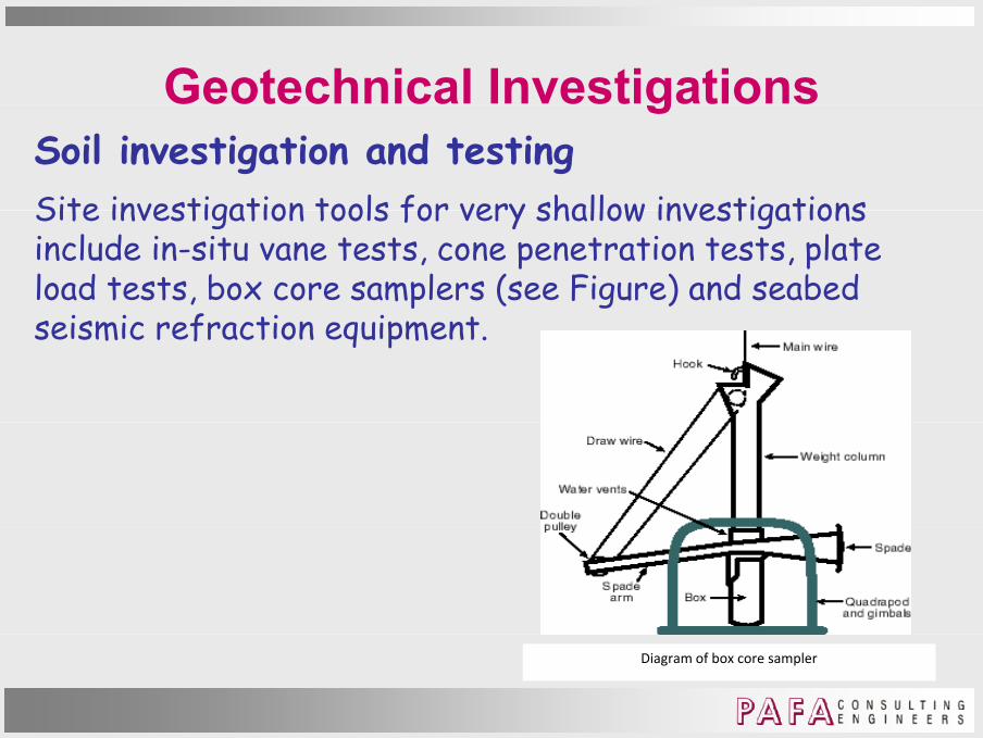
Site investigation tools for very shallow investigations include in-situ vane tests, cone penetration tests, plate load tests, box core samplers (see Figure) and seabed
i i f i iseismic refraction equipment.
Diagram of box core sampler

Seismic Hazard SurveysSeismic hazards• ground motions – basis input to seismic assessment in
y
• ground motions – basis input to seismic assessment in ISO 19901-2
• soil liquefaction - cyclic motions of saturated loose q ycohesionless soils
• sea floor slides – of normally stable slopesf lt t ll t b id d• fault movement – generally to be avoided
• tsunamis – destructive power now well understood• mud volcanoes – often at pre existing faults avoid• mud volcanoes – often at pre-existing faults - avoid• shock waves – usually only with most severe earthquakes.

Seismic Hazard SurveysSeismic hazardsISO 19901-2 Seismic Design Procedures and Criteria
y
ISO 19901-2 Seismic Design Procedures and Criteria requires jacket structure subject to seismic activity be designed for two levels of seismic actions:• extreme level earthquakes (ELE) checked at ULS• abnormal level earthquakes (ALE) checked at ALS. U d ELE t t t t ff t t l dUnder ELE, structure not to suffer structural damage.Under ALE, may suffer considerable damage but its overall integrity is not to be compromised to the extent that loss integrity is not to be compromised to the extent that loss of life or major environmental damage occurs.

Seismic Hazard SurveysSeismic hazardsISO 19901-2 assigns Seismic Risk Category via:
y
ISO 19901-2 assigns Seismic Risk Category via:a) site seismic zone
b) target annual probability of failure Pf

Seismic Hazard SurveysSeismic hazardsc) seismic risk category (SRC)
y
c) seismic risk category (SRC)

Seismic Hazard SurveysSeismic hazardsISO 19902-1 seismic design requirements
y
ISO 19902-1 seismic design requirements
Annex B provides seismic maps as part of Regional InformationInformation.
Seismic Hazard SurveysSeismic hazardsAnnex B: Regional Information
y
Annex B: Regional Information
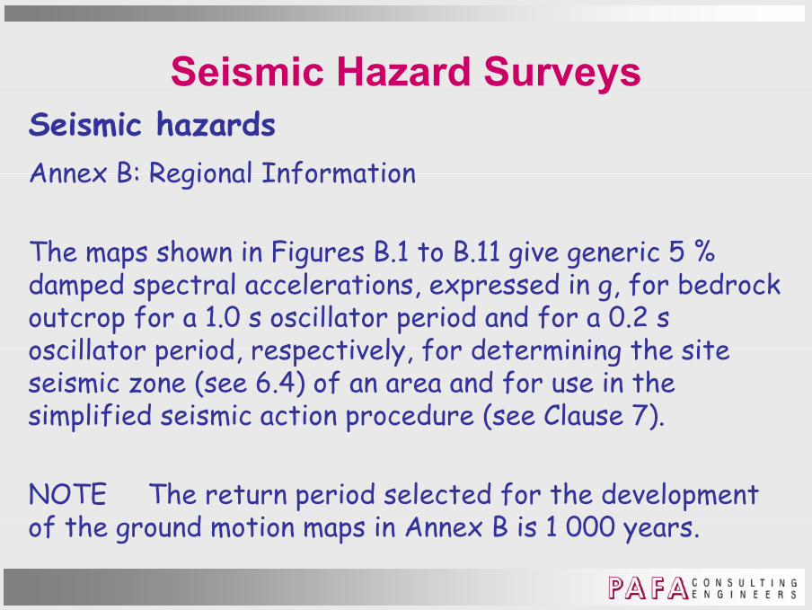
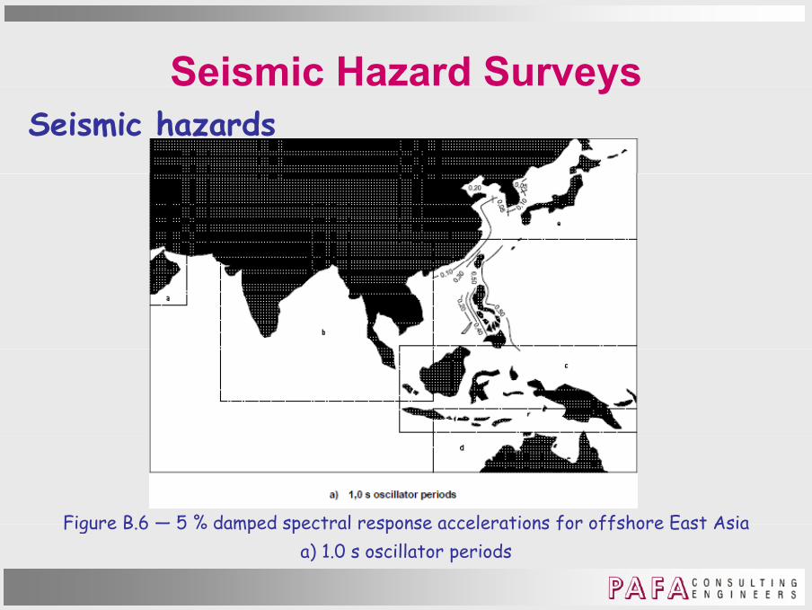
The maps shown in Figures B.1 to B.11 give generic 5 % he maps shown n F gures B. to B. g ve gener c 5 % damped spectral accelerations, expressed in g, for bedrock outcrop for a 1.0 s oscillator period and for a 0.2 s oscillator period respectively for determining the site oscillator period, respectively, for determining the site seismic zone (see 6.4) of an area and for use in the simplified seismic action procedure (see Clause 7).
NOTE The return period selected for the development of the ground motion maps in Annex B is 1 000 yearsof the ground motion maps in Annex B is 1 000 years.
Seismic Hazard SurveysSeismic hazards
y
Figure B 6 — 5 % damped spectral response accelerations for offshore East AsiaFigure B.6 — 5 % damped spectral response accelerations for offshore East Asiaa) 1.0 s oscillator periods

Seismic Hazard SurveysSeismic hazards
y
Figure B 6 — 5 % damped spectral response accelerations for offshore East AsiaFigure B.6 — 5 % damped spectral response accelerations for offshore East Asiab) 0.2 s oscillator periods

Seismic Hazard SurveysSeismic hazards
y
a) 1.0 s oscillator periods b) 0.2 s oscillator periodsFigure B 7 — 5 % damped spectral response accelerations for offshore East AsiaFigure B.7 — 5 % damped spectral response accelerations for offshore East Asia

Seismic Hazard SurveysSeismic hazards
y
a) 1.0 s oscillator periods
b) 0.2 s oscillator periods
Figure B.7 — 5 % damped spectral response accelerations for offshore East AsiaFigure B.7 5 % damped spectral response accelerations for offshore East Asia

Metocean DataGeneral considerationsTwo sets of conditions :1. Normal metocean conditions – for frequent operations.2 E di i f d i i d 2. Extreme metocean conditions - for design return period or probability of occurrence/exceedance.
Parameters should be determined from site measurements or from suitably validated model data such as hindcast modelsmodels.For dynamically sensitive structures, capture relevant wave and metocean parameter frequencies.

Metocean DataWater Depth, Tides and Storm SurgesWater depth important as it affects:• environmental actions on the structure;
l i f b l di f d d ll d k • elevations of boat landings, fenders, and cellar deck on bottom founded structures;• riser length/stroke on floating structures;riser length/stroke on floating structures;• mooring forces for taut or vertically moored floating structures.

Metocean DataWater Depth, Tides and Storm SurgesWater depth generally taken as fixed at LAT or MSL.Variations with respect to this level due to astronomical tide and storm surge (positive or negative)tide and storm surge (positive or negative).Tidal variations - result of gravitational and rotational interaction between the sun, moon and earth - regular and , glargely predictable - bounded by HAT and LAT.Bottom founded structures in shallow water, in particular, n d d kn l d f j int dist ib ti n f th tid need good knowledge of joint distribution of the tide, storm surge, and wave crest and trough elevations.

Metocean DataWater Depth, Tides and Storm SurgesVariations in daily astronomical tides determine elevations of boat landings, fenders, splash-zone treatment, conductors and risers and upper limits of marine growth conductors and risers, and upper limits of marine growth for bottom founded structures.Storm surges - random events - superimposed on tidal variations, such that total still water levels above HAT and below LAT can occur.

Metocean DataWater Depth, Tides
and Storm SurgesNoted above, water depth
Ekofisk Complex , p
normally taken as fixed at LAT or MSL.H s bsid However, subsidence can increase water depth.
Subsidence bowl contours

Metocean DataWind
d d f h h f d Standard reference height for wind is 10 m above MSL.Either sustained or gust speeds.Gusts include squalls thunderstorms etc Thus ratio of Gusts include squalls, thunderstorms, etc. Thus ratio of maximum gust speed to hourly mean wind speed is large.However, gusts during high hourly wind speeds is simply , g g g y p p yturbulence – at sea, typical gust to hourly wind speed = 1.5.For design, also have to account for structural response.Shorter gusts (3 sec) are coherent over shorter distances so affect smaller components than 15 sec gusts.

Metocean DataWind
f l ( ) ( ) l ( / ) ISO 19901-1 profile U1hr (z) = U1hr (10m) [1 + C ln(z/10m)]
For 10m reference level C = 0 573 [1 + 0 15 U (10m)]0 5For 10m reference level C = 0.573 [1 + 0.15 U1hr (10m)]0.5
ISO 19901-1 Annex A provides an equation to convert ISO 19901 1 Annex A provides an equation to convert between different time averaging intervals.

Metocean DataWind
d d d Wind direction is summarised in the form of a wind rose. This indicates the direction, usually , u u yin 30° sectors, from which the wind blows. Each radial vector usually has two scales one for usually has two scales, one for wind speed and the other for proportion of the time in one
h h d bl f year that the wind blows from the direction under consideration for each wind fspeed.

Metocean DataWind
f f l Annex C of ISO 19901-1 contains informative Regional Information in form of typical wind, wave and current values that can be used in preliminary design.u u p m y g .Covers North-West Europe, West Coast Africa, Gulf of Mexico, US Coast of California, East Coast Canada.

Metocean DataWind
f d f Annex C of ISO 19901-1 does not contain informative Regional Information for any of Middle East, Asia or Australasia.u .However, relevant ISO committee is currently assembling Regional Information for regionapparently denoted “East Asian Sea”

Metocean DataWind
l f d Typical information contained in Annex C:

Metocean DataWind
k / dJackets/Topsides:- API RP 2A adopts:
3 sec gust for static wind loads on individual members- 3 sec gust for static wind loads on individual members- 5 sec gust for total static load maximum horizontal dimension < 50 m- 15 sec gust for total static load maximum horizontal dimension > 50 m- 1 min sustained speed for global hydrodynamic loads when structure dynamically sensitive to wind- 1 h sustained speed for global hydrodynamic loads 1 h sustained speed for global hydrodynamic loads when structure not dynamically sensitive to wind.

Metocean DataWind
l l d l d d - ISO 199901-3 relies on national and regional standards so will vary according to location.Floaters - ISO 19904-1:Floaters - ISO 19904-1:Average wind velocities over appropriate time intervals:• small components - typically 3 sp yp y• stability calculations - 1 min • mean wind actions in conjunction with frequency or time domain gust analysis – typically 1 h.Jack-ups - ISO 19905-1:Uses 1 minute sustained wind speedUses 1 minute sustained wind speed.

Metocean DataWavesWaves - irregular in shape vary in Waves - irregular in shape, vary in height, length and speed of propagation, and approach a structure f di ti from one or more directions simultaneously. So a sea state is best described by ymeans of a random linear wave model.

Metocean DataWavesTwo main assumptions in interpreting wave data Two main assumptions in interpreting wave data. 1. waves can be described as a summation of sine waves of
varying frequency, amplitude and direction. 2 d t t ti ti ll t ti i t ti ti l 2. data are statistically stationary, i.e. statistical
description of a wave field at a given time is essentially the same as the description that would be obtained at a pslightly different time.
The process of converting wave field data into its The process of converting wave field data into its sinusoidal components is called a Fourier analysis after the French mathematician who first proposed the idea in 1807.

Metocean DataWavesStatistically stationary wave fields are never achieved as Statistically stationary wave fields are never achieved as they are constantly evolving (i.e. growing or decaying).To reduce statistical scatter, wave record should contain at l t 200 d i ( fi ) least 200 zero-down crossing waves (see figure). Optimal time over which waves are usually measured is 15–35 minutes, as this reasonably accommodates both , yconditions. 20 minute records are now relatively universal.
Dashes – wave crestsDashes wave crestsCircles – zero
down-crossings
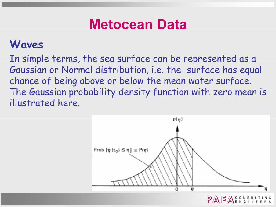
Metocean DataWavesIn simple terms the sea surface can be represented as a In simple terms, the sea surface can be represented as a Gaussian or Normal distribution, i.e. the surface has equal chance of being above or below the mean water surface.Th G i b bilit d it f ti ith i The Gaussian probability density function with zero mean is illustrated here.

Metocean DataWavesData analyses are performed by computer using digital Data analyses are performed by computer using digital records. Data are vertical displacements of ocean surface at sampling rates of 1–10 Hz.
Wave data analysis is based on a sinusoidal wave profile.

Metocean DataWaves
Sinusoidal wave profile
( t) i (k t)η(x, t) = a sin (k x – ω t)
where x, t are space and time coordinates,, p ,k = 2 π/ λ is the wave number and λ is the wavelength,ω= 2 π/T is the angular frequency and T is the wave period (time between consecutive down-crossings or up-crossings)(time between consecutive down-crossings or up-crossings)a = amplitude (= wave height H/2).

Metocean DataWavesLinear random wave model views the sea as superimposition Linear random wave model views the sea as superimposition of many small individual frequency components.Each component is a periodic wave with its own amplitude, f d di ti f tifrequency and direction of propagation.The components have random phase relationships with respect to each other.p
Two broad classes of wave conditions:- Locally generated waves – wind seas- Locally generated waves wind seas- Remotely generated waves – swell.

Metocean DataWaves - Maximum Individual Wave Height
Determined from measurements and appropriate statistical methods, orhi d t d l hi h l ti l d l b d hindcast models which are analytical models based observations of the underlying physical parameters.
Typically maximum design wave height based on 100 year return period or 0.01 probability of exceedance.

Metocean DataWaves - Maximum Individual Wave HeightLong-term distribution is determined by convolution of the Long-term distribution is determined by convolution of the long-term distribution derived from the data with a short-term distribution that accounts for the uncertainty in i di id l h i ht i t tindividual wave heights in a sea state.More statistically correct approach based on storms using storms with peak significant wave height above a p g gparticular threshold.Alternatively, when only short data series available (2 -3 years) use sea states instead of storms This suffers years), use sea states instead of storms. This suffers because it ignores sea states that are lower but more frequent than the estimated N-year return period i ifi t h i ht d th t t th t significant wave height and then uses sea states that are
less frequent but higher than this estimated value.

Metocean DataWaves - Maximum Individual Wave HeightAlthough the sea surface is Gaussian distributed wave Although the sea surface is Gaussian distributed, wave heights can only be positive and so are represented by a one-sided distribution.Cl i ll th di t ib ti f h i ht i d t Classically, the distribution of wave heights is assumed to be narrow banded and described by the Rayleigh distribution, thus the cumulative probability is , p y
P(H ≤ H*) = 1 - exp[-2(H*/Hs)2]
H* = any desired value of significant wave heightHs = N year return period significant wave height

Metocean DataWaves - Maximum Individual Wave HeightRayleigh probability density functionRayleigh probability density functionσ= standard deviatione = exponential function

Metocean DataWaves - Maximum Individual Wave Height
In practice, seas not normally narrow-banded.
Using Rayleigh over-predicts wave height. Empirical distributions proposed to take account for finite b d idthbandwidth.

Metocean DataWaves - Maximum Individual Wave Height
Example - Forristall, used Gulf of Mexico hurricane wave data, to derive a finite bandwidth distribution.
P(H ≤ H*) = 1 - exp[-(4 H*/Hs)α/β]
α = 2.126 (= 2 for a Rayleigh distribution)β = 8.42 (= 8 for a Rayleigh distribution)

Metocean DataWaves - Maximum Individual Wave HeightThe consequence for the Rayleigh distribution of The consequence for the Rayleigh distribution of introducing a finite bandwidth is given here.Bandwidth parameter ε2 = [m0m4 – m2
2]/(m0m4)kth t f tkth moment of wave spectrummk = ∫ωkG(ω)dω

Metocean DataWaves - Maximum Individual Wave HeightIn the Rayleigh equation the parameter ‘significant wave In the Rayleigh equation, the parameter significant wave height’ was used.Hs is defined as the average of the highest one-third of
h i hwave height.

Metocean DataWaves - Maximum Individual Wave HeightWave height relationships based on the Rayleigh Wave height relationships based on the Rayleigh distribution.

Metocean DataWaves – Wave Crest Elevation For:For:• setting minimum deck heights on bottom founded structures
i th b bilit f t t t id • assessing the probability of green water onto topsides of all types of structures and decks and hulls which are intended to be kept above the waves. p
Require distribution of extreme and abnormal crest elevations elevations.

Metocean DataWaves – Wave Crest Elevation Crest elevation enhanced by presence of structure can be Crest elevation enhanced by presence of structure can be significant for caisson structures or those with large diameter legs.
Enhancement does not necessarily lead to large global actions but more usually significant local pressures on the y g punderside or other exposed parts of topsides.
Similar approaches to those used for maximum wave Similar approaches to those used for maximum wave heights can be applied.

Metocean DataWaves – Wave Crest Elevation ISO 19901-1ISO 19901-1Alternatively, exploit second-order random directional wave theory, e.g. Weibull distribution (for a range of
t d th d t )water depths and wave steepnesses)
P(η > η* | Hs) = exp[-(η/αHs) β](η η | s) p[ (η s) ]
where α and β are empirical functions of wave steepness (S1) and Ursell number (U )(S1) and Ursell number (Ur).

Metocean DataWaves – Wave Crest Elevation ISO 19901-1ISO 19901-1
S1 = 2πHs/gT12 Ur = Hs/(k1
2d3)
T1 = mean period = m0/m1k1 = wave number for a wave frequency 2π/T11 q y 1d = water depth
For a spread seaFor a spread seaα = 0,3536 + 0,2568 S1 + 0,0800 Ur
β 2 1 7912 S 0 5302 U 0 284 U 2β = 2 – 1,7912 S1 – 0,5302 Ur + 0,284 Ur2

Metocean DataWaves – Wave SpectraA unidirectional random sea is a special case of the A unidirectional random sea is a special case of the generalized random sea, where all frequency components propagate in the same direction.Th f f idi ti l i l t d The surface of a unidirectional sea is long-crested whereas the surface of a real or directional sea is short-crested.In the linear random wave model, the sea state is completely described by the directional wave spectrum S (ω θ) where ω is frequency and θ is directionS (ω, θ) where ω is frequency and θ is direction.Usually the frequency characteristic are assumed independent of direction and directional characteristics i d d t f findependent of frequency.

Metocean DataWaves – Swell SpectraWave frequency spectra for swells are generally much Wave frequency spectra for swells are generally much narrower than spectra for wind seas.
L i d ll f di t t t l Long-period swells from distant storms are more or less symmetrical in shape around a dominant modal frequency.
Can use JONSWAP function but symmetric Normal or Gaussian function generally better to describe particularly long-period swelllong-period swell.

Metocean DataWaves – Wave Spectra – Frequency Widely used wind seas frequency spectra include:Widely used wind seas frequency spectra include:
• Pierson-Moskowitz for fully developed seas
• JONSWAP for fetch-limited seas

Metocean DataWaves – Wave Spectra – Frequency
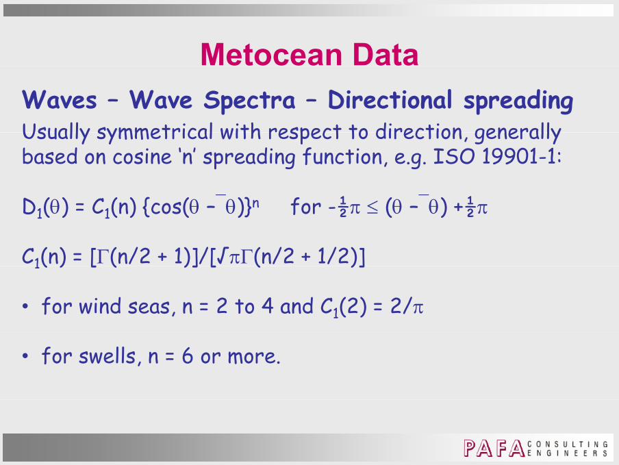
Metocean DataWaves – Wave Spectra – Directional spreadingUsually symmetrical with respect to direction generally Usually symmetrical with respect to direction, generally based on cosine ‘n’ spreading function, e.g. ISO 19901-1:
D (θ) C ( ) { (θ θ)} f ½ (θ θ) ½D1(θ) = C1(n) {cos(θ – θ)}n for -½π ≤ (θ – θ) +½π
C1(n) = [Γ(n/2 + 1)]/[√πΓ(n/2 + 1/2)]1( ) [ ( )] [ ( )]
• for wind seas, n = 2 to 4 and C1(2) = 2/π
• for swells, n = 6 or more.

Metocean DataCurrent – General• Affect location/orientation of boat landings/fenders• Affect location/orientation of boat landings/fenders• Generate sea floor scouring• Can have adverse effect on operating practices
I fl i t l ti d ti ff t • Influence environmental actions and action effects on structure.
Current velocity generally varies through the water column and in combination with waves, has to be stretched to the water surfacewater surface.Currents are modified by the presence of typical space-framed offshore structures – blockage.

Metocean DataCurrent – VelocitiesMuch slower temporal and spatial variations than wind so Much slower temporal and spatial variations than wind, so velocity generally only considered as function of depth.
V t f tid l d id l tVector sum of tidal and residual currents.
Tidal - regular and predictable, maximum values precede g p , por follow HAT and LAT.
Generally weak in deep water and stronger on broad Generally weak in deep water, and stronger on broad continental shelves than on steep shelves.

Metocean DataCurrent – VelocitiesCan be strengthened by shoreline or sea floor Can be strengthened by shoreline or sea floor configurations so strong tidal currents exist in many inlets and coastal regions - surface values up to 3 m/s.
Residual current- components of circulation/storm generated currentsp g- short/long period currents generated by density gradients, wind stress, and internal waves- often irregular with storm surge the largest component- often irregular with storm surge the largest component.

Metocean DataCurrent – VelocitiesCirculation currents - deep water relatively steady large Circulation currents - deep water relatively steady, large scale features of general oceanic circulation.
Examples Gulf Stream Atlantic Ocean Examples - Gulf Stream, Atlantic Ocean - Loop Current, Gulf of Mexico.
Ci l ti f t hil t l ti l t d d d Circulation features, whilst relatively steady, meander and intermittently break off from main circulation to become large scale eddies or rings, which then drift slowly with g g yvelocities that can approach or exceed that of the main circulation feature of 1 to 2 m/s.

Metocean DataCurrent – VelocitiesStorm generated currents - caused by wind stress and Storm generated currents - caused by wind stress and pressure gradient throughout a storm.
C l f ti f t t th t l i l Complex function of storm strength, meteorological characteristics, bathymetry and shoreline configuration, and water density profile. y p
In deep open water, surface storm current up to 3% of the 1 hour sustained wind speed Both storm surge and the 1 hour sustained wind speed. Both storm surge and current increase as storm approaches coastline/shallower water.

Metocean DataCurrent – ProfileWhere current direction through water column is Where current direction through water column is relatively constant, simple profiles are appropriate.
Sh ll t t fil h tid d i t Shallow water current profiles where tides dominate – use simple power laws of velocity versus depth.
Deep water profiles more complex with reversals of direction with depth.

Metocean DataCurrent – Profile StretchingCurrent speeds and profiles are determined for still water Current speeds and profiles are determined for still water conditions.
B t t t h d th t fil d But waves stretch and compress the current profile under crests and troughs.
Stretching - instantaneous current speed Uc(z) at a depth z (+ve up from still water level) is effective at a stretched vertical coordinate zvertical coordinate zs.
Both linear and non-linear stretching methods are used.

Metocean DataCurrent – Profile
Stretching
ISO 19901-1 ISO 19901 1 stretching of sheared current
Metocean DataCurrent – Profile Stretching
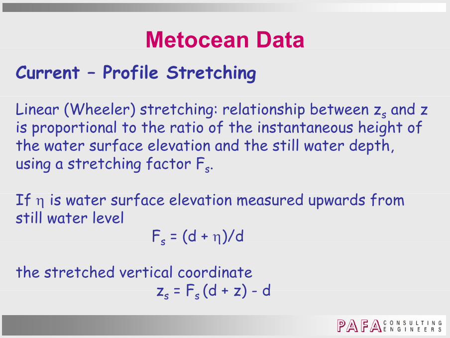
Linear (Wheeler) stretching: relationship between zs and z is proportional to the ratio of the instantaneous height of the water surface elevation and the still water depth the water surface elevation and the still water depth, using a stretching factor Fs.
f f l d d f If η is water surface elevation measured upwards from still water level
Fs = (d + η)/dFs ( η)/
the stretched vertical coordinatez = F (d + z) dzs = Fs (d + z) - d

Metocean DataCurrent – Profile Stretching
Non-linear stretching: zs and z are related through linear (Airy) wave theory by:
sinh[ ( )]sinh( )
nls
nl
k z dz zk d
η += +
knl = non-linear wave number = 2π/λnl
λ = wave number of regular wave under consideration for λn = wave number of regular wave under consideration for water depth d and wave height H calculated using non-linear wave theory and the intrinsic wave period.
Metocean DataCurrent – Profile Stretching
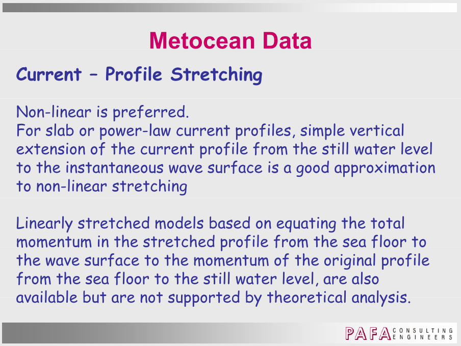
Non-linear is preferred. For slab or power-law current profiles, simple vertical extension of the current profile from the still water level extension of the current profile from the still water level to the instantaneous wave surface is a good approximation to non-linear stretching
Linearly stretched models based on equating the total momentum in the stretched profile from the sea floor to m m m p f f m fthe wave surface to the momentum of the original profile from the sea floor to the still water level, are also available but are not supported by theoretical analysisavailable but are not supported by theoretical analysis.

Metocean DataWaves - Doppler Effect & Apparent Wave PeriodCurrent lengthens a wave if moving in same directionCurrent lengthens a wave if moving in same direction
Current shortens a wave if moving in opposite direction.
The basic or intrinsic frame of reference for wave assumes the reference frame is stationary.y
For an observer on a fixed platform, the current affects the encounter frequency of the waves so the observer sees more encounter frequency of the waves so the observer sees more frequent waves if wave and current directions are the same. In this case the apparent wave period Ta is shorter than the i t i i i d Tintrinsic period Ti.

Metocean DataWaves - Doppler Effect & Apparent Wave PeriodAn observer on a moving vessel measures the encounter waveAn observer on a moving vessel measures the encounter waveperiod, Te.
Th diff b t T d T d d th l ti The difference between Te and Ti depends on the relative speeds and directions of the moving vessel and of the current.
If the moving vessel is travelling at the same speed and in the same direction as the current T = Tthe same direction as the current Te = Ti.

Metocean DataWaves - Doppler Effect & Apparent Wave PeriodIf wave period is derived from measurements taken by fixed If wave period is derived from measurements taken by fixed (rather than drifting) instruments, the measurements give the apparent wave period.
If wave period is based on hindcasts of waves with a model that is calibrated to measurements taken by fixed yinstruments, and no adjustments are made to the model to account for the presence of current, then again the wave period represents the apparent wave period period represents the apparent wave period.
In both cases the intrinsic wave period should be calculated f th t i dfrom the apparent wave period.

Metocean DataWaves - Doppler Effect & Apparent Wave PeriodIn calculating wave particle kinematics some computer In calculating wave particle kinematics, some computer programs adjust the wave period / length internally to account for currents.
Other programs require the user to manually adjust the wave period before using it to compute kinematics. The user needs p g pto ensure that the correct procedure is applied.

Metocean DataWaves - Doppler Effect & Apparent Wave PeriodISO 19901-1 - gives the relationship between the apparent ISO 19901-1 - gives the relationship between the apparent and intrinsic periods as
λ/T λ/T Vλ/Ta = λ/Ti + Vin-line
λ = wave lengthgVin-line = component of velocity in-line with wave direction.
While strictly applicable only to a current uniform over the While strictly applicable only to a current uniform over the full water depth, figure on next slide provides acceptable estimates of Ti/Ta for “slab” current profiles that are
if th t 50 f th t luniform over the top 50 m or more of the water column.

Metocean DataWaves - Doppler Effect & Apparent Wave PeriodISO 19901-1 and API RP 2A use identical formulations for ISO 19901-1 and API RP 2A use identical formulations for the Doppler effect.
However, recent Gulf of Mexico hurricane current profile t t ‘ l b’ t t il tassessment suggests ‘slab’ current not necessarily correct.

Metocean DataWaves - Doppler Effect & Apparent Wave Period

Metocean DataSource Data for Regionhttp://agora ex nii ac jp/digital-typhoon/index htmlhttp://agora.ex.nii.ac.jp/digital-typhoon/index.htmlTop 15 typhoons from 1951 to 2011.

Wave TheoriesWaves
2D Wave Theory
ISO 19901-1 ≡ API RP 2A

Wave TheoriesWaves - 2D Wave Theory

Wave TheoriesWaves - 2D Wave Theory

Wind & Wave ForcesWind
&
Before Katrina After Katrina

Wind & Wave ForcesWaves
&
After Gustav and Ike

Wind & Wave ForcesWaves
&
More from Gustav and IkeMore from Gustav and Ike

Wind and Wave ForcesWavesMain source of environmental loading for most offshore Main source of environmental loading for most offshore regions.Because of challenge of collecting and interpreting wave d t ti l l f l t di ti d d data, particularly for long-term predictions, care needed in determining wave actions and action effects.Wave force predictions originally from API RP 2A but now p g yfrom:- ISO 19902 fixed steel structures- ISO 19904-1 floaters (monohull semi-subs spars)- ISO 19904-1 floaters (monohull, semi-subs, spars)- ISO 19905-1 site-specific assessment of jack-ups- ISO 19901-3 topsides.
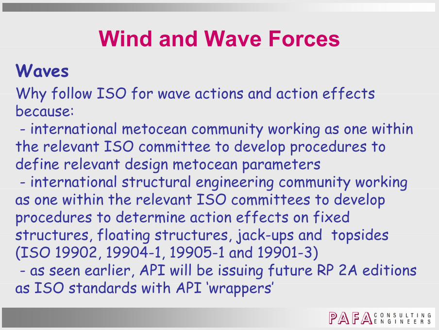
Wind and Wave ForcesWavesWhy follow ISO for wave actions and action effects Why follow ISO for wave actions and action effects because:- international metocean community working as one within th l t ISO itt t d l d t the relevant ISO committee to develop procedures to define relevant design metocean parameters- international structural engineering community working g g y gas one within the relevant ISO committees to develop procedures to determine action effects on fixed structures floating structures jack-ups and topsides structures, floating structures, jack-ups and topsides (ISO 19902, 19904-1, 19905-1 and 19901-3)- as seen earlier, API will be issuing future RP 2A editions
ISO t d d ith API ‘ ’as ISO standards with API ‘wrappers’
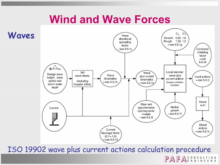
Wind and Wave ForcesWaves
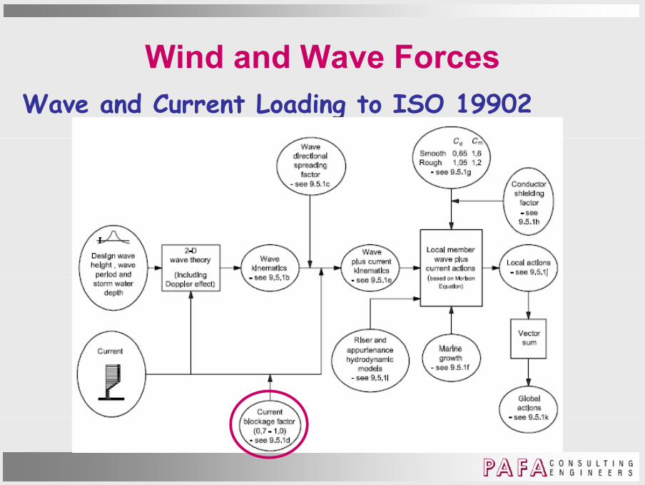
ISO 19902 wave plus current actions calculation procedure

Wind and Wave ForcesWaves
API RP 2A wave plus current actions calculation procedure

Wind and Wave ForcesWave and Current Loading to ISO 19902

Wind and Wave ForcesWave and Current Loading to ISO 19902Design wave height wave period current and storm Design wave height, wave period, current and storm water depth
Cl 9 4 l di i i t ti i i d iClause 9.4 – loading is quasi-static, i.e. ignores dynamics
Design return period 100 years. g p y
Three choices for defining relevant metocean parameters:

Wind and Wave ForcesWave and Current Loading to ISO 19902Design wave height wave period current and storm Design wave height, wave period, current and storm water depth
) 100 t i d h i ht ( i ifi t a) 100 year return period wave height (significant or individual) with associated wave period, wind and current velocities;
b) 100 year return period wave height and period combined with the 100 year return period wind speed and the 100 year return period current velocity all determined by year return period current velocity, all determined by extrapolation of the individual parameters considered independently;

Wind and Wave ForcesWave and Current Loading to ISO 19902Design wave height wave period current and storm Design wave height, wave period, current and storm water depth
) bl bi ti f h i ht d i d c) any reasonable combination of wave height and period, wind speed and current velocity that results inthe global extreme environmental action on the gstructure with a return period of 100 years, ora relevant action effect (global response) of the structure (e g base shear or overturning moment) with a structure (e.g. base shear or overturning moment) with a return period of 100 years.

Wind and Wave ForcesWave and Current Loading to ISO 19902Design wave height wave period current and storm Design wave height, wave period, current and storm water depth
Method a) - established practice in some regions for Method a) established practice in some regions for deriving wind and current extremes occurring simultaneously with wave height (e.g. USA).The specified return period is usually 100 years. Used to derive secondary parameters (wave periods) in North Sea The “associated” wave period current or wind North Sea. The associated wave period, current, or wind is the value expected to co-exist with the specified return period wave height.

Wind and Wave ForcesWave and Current Loading to ISO 19902Design wave height wave period current and storm Design wave height, wave period, current and storm water depth
Method a) Method a) The method is applicable if:
there is a statistically significant correlation between y gthe associated value and the specified return period wave height; and
the extreme lobal environmental action on the the extreme global environmental action on the structure is dominated by waves.
Wind and Wave ForcesWave and Current Loading to ISO 19902Design wave height wave period current and storm Design wave height, wave period, current and storm water depth
Method b) - used in North Sea and many other areas Method b) used in North Sea and many other areas, normally with a return period of 50 or 100 years.A modified version, using the 100 year wave height and the 100 year wind speed combined with the 10 year current velocity, has been used in Norway.

Wind and Wave ForcesWave and Current Loading to ISO 19902Design wave height wave period current and storm Design wave height, wave period, current and storm water depth
Method c) - involves calculating an associated current and Method c) involves calculating an associated current and wind speed using the wave height and a critical structural response (action effect), e.g. base shear or overturning
t f fi d t t h i t l di l t moment for fixed structures or horizontal displacement for a floating structure. Directional effects of wind, wave and current, and water Directional effects of wind, wave and current, and water depth fluctuation due to tide and surge are fully accounted for.

Wind and Wave ForcesWave and Current Loading to ISO 19902Design wave height wave period current and storm Design wave height, wave period, current and storm water depth
Method c) Method c) Storms are treated as independent events and short-term uncertainty is taken into account. The long-term distribution of response is determined and from this, its extreme and abnormal values.The same response function can be used to determine The same response function can be used to determine combinations of metocean parameters leading to the desired return period extreme and abnormal responses.

Wind and Wave ForcesWave and Current Loading to ISO 19902Design wave height wave period current and storm Design wave height, wave period, current and storm water depth
Method c) Method c) Note that the derived set of parameters is not unique; several other related sets will produce the same result. In addition, the statistics can be used in the development of partial factors for environmental actions (action effects)effects).

Wind and Wave ForcesWave and Current Loading to ISO 19902

Wind and Wave ForcesWave and Current Loading to ISO 19902

Wind and Wave ForcesWave and Current Loading to ISO 19902
Wind and Wave ForcesWave and Current Loading to ISO 19902

Wind and Wave ForcesWave and Current Loading to ISO 19902Current blockage factorCurrent blockage factor
No space frame or lattice type structure is totally transparent to waves and current transparent to waves and current. The structures cause global distortion of the incident waves and of the current in and around the structure.Because global hydrodynamic action is calculated by summing hydrodynamic actions on individual members, it is important that the local incident flow be used to calculate important that the local incident flow be used to calculate hydrodynamic action on individual members.

Wind and Wave ForcesWave and Current Loading to ISO 19902Current blockage factorCurrent blockage factor
For currents, the amount of blockage depends on the type of structure of structure. For dense structures it will be large, while for very transparent structures it will be small.Laboratory/field data indicate the following factors:- 0.6 for dense structures (e.g. the Lena guyed tower)
0 f l l - ≈ 0.7 for typical compliant tower- ≈ 0.75 to 0.85 for typical space frame structures – see ISO 19902 Table A 9 5-1 (below)ISO 19902 Table A.9.5 1 (below).

Wind and Wave ForcesWave and Current Loading to ISO 19902Current blockage factorCurrent blockage factorMeasured current field at 18 m depth,B ll i kl Bullwinkle, Loop Current, Gulf of Mexico, 1991. 1991. Average blockage factor within the structure is 0.77.

Wind and Wave ForcesWave and Current Loading to ISO 19902Current blockage factorCurrent blockage factor
F t i l j k t l f T bl A 9 5 1For typical jackets, use values from Table A.9.5-1.

Wind and Wave ForcesWave and Current Loading to ISO 19902Current blockage factorCurrent blockage factor
For non-typical jackets, use ISO 19902 equation A.9.5-2:F [ 1 Σ(C A) /4Â] 1 b t 0 7Fb = [ 1 + Σ(CdA)i/4Â]-1 but ≥ 0.7
Σ(CdA)i = summation of “drag areas” of all members (including horizontal members) in the flow(including horizontal members) in the flow
 = area within structure perimeter area projected normal to the current, i.e. plan area, which can be , p ,calculated for as many levels as necessary for jackets with significant leg batter.
F 1 0 f st di /b d iss s t i d st t sFb = 1.0 - free-standing/braced caissons, tripod structures

Wind and Wave ForcesWave and Current Loading to ISO 19902

Wind and Wave ForcesWave and Current Loading to ISO 19902Wave plus Current KinematicsWave plus Current Kinematics
When ratio wave length/member diameter > 5, wave/ current loading given be Morison’s equationcurrent loading given be Morison s equation.
F = Fd + Fi
Fd = Cd ½ ρw U |U| A – drag action per unit length, normal to member axis, in plane of member axis & U
Fi = Cm ρw V ∂U/∂t – inertia action per unit length, normal to member axis in plane of member axis & ∂U/∂tto member axis, in plane of member axis & ∂U/∂t
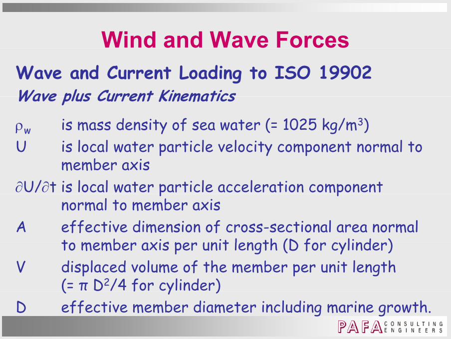
Wind and Wave ForcesWave and Current Loading to ISO 19902Wave plus Current KinematicsWave plus Current Kinematics
ρw is mass density of sea water (= 1025 kg/m3)U is local water particle velocity component normal to U is local water particle velocity component normal to
member axis∂U/∂t is local water particle acceleration component p p
normal to member axisA effective dimension of cross-sectional area normal
to member axis per unit len th (D for cylinder)to member axis per unit length (D for cylinder)V displaced volume of the member per unit length
(= π D2/4 for cylinder)( f y )D effective member diameter including marine growth.

Wind and Wave ForcesWave and Current Loading to ISO 19902Wave plus Current KinematicsWave plus Current Kinematics
When ratio wave length/member diameter < 5, incident waves are scattered or diffracted waves are scattered or diffracted. In “diffraction regime”, compute pressures on structure due to both the incident and scattered waves.

Wind and Wave ForcesWave and Current Loading to ISO 19902

Wind and Wave ForcesWave and Current Loading to ISO 19902Hydrodynamic models for appurtenancesHydrodynamic models for appurtenances
Appurtenances - boat landings, fenders, grout lines, anodes – to be included in the hydrodynamic model anodes to be included in the hydrodynamic model. Appurtenances can significantly increase global hydrodynamic action on the structure. Also, hydrodynamic actions on some appurtenances can be important for local member design. Modelled by non-structural ‘hydrodynamic’ members Modelled by non-structural hydrodynamic members. Some appurtenances, e.g. boat landings, the hydrodynamic action is dependent on wave direction due to shielding effects.

Wind and Wave ForcesWave and Current Loading to ISO 19902

Wind and Wave ForcesWave and Current Loading to ISO 19902Marine GrowthMarine Growth
Increase cross-sectional dimensions of components, conductors etc to account for marine growthconductors, etc, to account for marine growth.Classify circular components as “smooth” or “rough”, depending on expected amount/size of marine growth at the time of the loading event. Structural elements - hydrodynamically smooth if above the HAT or sufficiently deep below LAT as marine growth the HAT or sufficiently deep below LAT, as marine growth accumulation here small enough to ignore.NOTE - it takes very little roughness to make the rough value of the Cd realistic so normally rough to sea floor.

Wind and Wave ForcesWave and Current Loading to ISO 19902

Wind and Wave ForcesWave and Current Loading to ISO 19902Drag and Inertia Coefficients
l l l lGlobal hydrodynamic action can be calculated using Morison’s equation using the typical Cd, Cm values for unshielded cylinders given in the figure.unsh cy n rs g n n th f gur .These values apply for “steady current with negligible waves” and for “large waves with UmoTi/D > 30” Umo = maximum horizontal water particle velocity from 2D wave theory at storm still water level under wave crest;T i t i si i d;Ti = intrinsic wave period;D = leg diameter at storm still water level.In “waves with U Ti/D < 30” vertical members suffer wave In waves with UmoTi/D < 30 , vertical members suffer wave encounter so Cd, Cm need to be specially determined.

Wind and Wave ForcesWave and Current Loading to ISO 19902

Wind and Wave ForcesWave and Current Loading to ISO 19902Conductor Shielding Factor kConductor Shielding Factor ks
A long recognized phenomenon. ISO 19902 Figure 9.5-2 in which D is conductor diameter and S centre-to-centre which D is conductor diameter and S centre to centre spacing.Only applies if:a) steady current with
negligible waves, orb) h b) extreme waves, with
UmoTi/S > 5 πOtherwise ignore shieldingOtherwise ignore shielding.

Wind and Wave ForcesWave and Current Loading to ISO 19902

Wind and Wave ForcesWave and Current Loading to ISO 19902Global ActionsGlobal Actions
After calculating the loading on all components of the platform the extreme global action caused by waves and platform, the extreme global action caused by waves and current is found as the vector sum of all the local actions.

Buoyancy and StabilityBuoyancy – Archimedes’ Principle
y y y

Buoyancy and StabilityBuoyancy – Archimedes’ Principle A body wholly or partially immersed in a fluid will
y y y
A body wholly or partially immersed in a fluid will experience an upward force equal and opposite to the weight of displaced fluid.Because density of fresh water and salt water differ (1000 to 1025 k / 3) th th 1025 kg/m3), then the same body will displace a greater volume of fresh than sea watervolume of fresh than sea water.Consequently, the body will have a smaller draft in sea than fresha smaller draft n sea than freshwater.

Buoyancy and StabilityBuoyancy – Archimedes’ Principle Basics of buoyancy calculation for a floating body:
y y y
Basics of buoyancy calculation for a floating body:a) Buoyancy equals weightb) Centres of buoyancy & gravity lie in same vertical plane) entres of uoyancy & gra ty e n same ert ca p anec) Any slight rotation from
this position will cause the weight and buoyancy forces to generate a moment to restore condition b).
VCG vertical centre of gravityVCG = vertical centre of gravityVCB = vertical centre of buoyancy

Buoyancy and StabilityBuoyancy – Archimedes’ Principle But why in this figure as the
y y y
But why in this figure, as the body rotates clockwise, does the VCB move to the right.the V B mo e to the r ght.As noted above, to be in equilibrium, when displaced, a restoring force has to be developed.

Buoyancy and StabilityHydrostatic Stability Consider a rectangular body with CoG
y y y
1Consider a rectangular body with CoG as shown – it floats half submerged.As shown in the figures below, the
1
3
CoG
gbody is in equilibrium with the CoG either at the top or at the bottom. In either case a restoring moment is
= =
In either case, a restoring moment is created to return the body to its original position.H f h b d ll However, if the body initially rotates further, at b) the restoring moment is lost sooner than at d) so only c) is ) y )the stable orientation.

Buoyancy and StabilityHydrostatic Stability For stability considerations require
y y y
For stability considerations, require definitions of “Righting or Restoring Moments” and “Heeling or Overturning M t ”Moments”.Righting moment: at any inclination, where the weight and buoyancy forces where the weight and buoyancy forces act to move a body toward the upright position – leads to positive stability.H l l h Heeling moment: at any inclination, where the weight and buoyancy forces act to move a body away from the upright m y y f m p gposition – leads to negative stability.
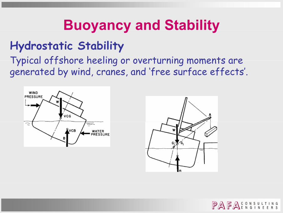
Buoyancy and StabilityHydrostatic Stability Typical offshore heeling or overturning moments are
y y y
Typical offshore heeling or overturning moments are generated by wind, cranes, and ‘free surface effects’.

Buoyancy and StabilityHydrostatic Stability Free surface effects
y y y
Free surface effectsOrientation of surface of liquid cargo unaffected by qu d cargo unaffected y heeling but the effect is to move centroid of the
Liquid cargo
cargo to the right – similar affect to crane Liquid cargoLiquid cargo
on the side.This movement can be reduced by the use of vertical bulkheads along the length of the body as shown in the bulkheads along the length of the body, as shown in the animation.

Buoyancy and StabilityHydrostatic Stability Metacentric Height
y y y
Metacentric Height For a heeled ship, VCB has moved off-centre. Vertical separation of lines of action is GZ – Righting Arm.Vert ca separat on of nes of act on s GZ ght ng rm.Inclined line of buoyancy action intersects original line of action at M – Metacentre.For small angles, GZ = GM sin dφGM – Metacentric heightGM siti h M b GGM positive when M above GGM negative when M below G.What are implications of negative GM?What are implications of negative GM?

Buoyancy and StabilityHydrostatic Stability Metacentric Height
y y y
Metacentric Height For an inclined ship, the volume of each wedge with CoGs g1and g2 is equal (volume = v ), and displacement unchanged.g q p gVCB moves along a line parallel to a line joining g1, g2.BB1 = v g1 g2 /∇∇= ship’s volumetric displacementBM = BB1/tan dφ
I /∇= IT/∇IT = moment of inertia of entire waterplane about the ship’s ent re waterplane about the sh p s longitudinal centre-line. K

Buoyancy and StabilityHydrostatic Stability Metacentric Height
y y y
Metacentric Height Measured up from the keel K, metacentre distance = KM.KM = IT/∇ + KBKM IT/ KBKB = height from keel to VCB.
The height of the VCG above the keel KG is determined from an inclining experiment.Th t t i h i ht GM KM KGThe metacentric height GM = KM - KG

Buoyancy and StabilityHydrostatic Stability Curves of Statical Stability
y y y
Curves of Statical StabilitySeen above that GZ is the righting arm.Plot GZ v angle of heelot GZ ang e of heeTypical plot

Buoyancy and StabilityHydrostatic Stability Requirements for Statical Stability
y y y
Requirements for Statical StabilityUK Health and Safety Executive Guidance for Offshore InstallationsPrimarily concerned with wind heeling

Buoyancy and StabilityHydrostatic Stability Requirements for Statical Stability
y y y
Requirements for Statical StabilityUK HSE Guidance for Offshore Installations

Buoyancy and StabilityHydrostatic Stability Requirements for Statical Stability
y y y
Requirements for Statical StabilityUK HSE Guidance for Offshore InstallationsWhy do coefficients increase Why do coeff c ents ncrease with height?

Buoyancy and StabilityHydrostatic Stability Intact Stability Criteria
y y y
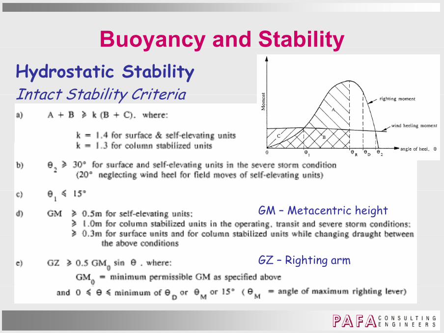
Intact Stability CriteriaHSE Guidance
Buoyancy and StabilityHydrostatic Stability Intact Stability Criteria
y y y
Intact Stability Criteria
GM – Metacentric height
GZ – Righting arm

Buoyancy and StabilityClass Exercises:1. Consider a floating cylindrical object and determine the
y y y
appropriate restoring force as it inclines.2. Check the equilibrium of a square homogenous log with a
specific gravity of 0 5 floating in water with:specific gravity of 0.5 floating in water with:a) One corner upb) One face up.) n f up.

Thank youThank you


![DAY 1 PANEL 1 Singapore Govt.ppt · Microsoft PowerPoint - DAY 1 PANEL 1 Singapore Govt.ppt [Compatibility Mode] Author: Administrator Created Date: 5/26/2011 1:41:50 PM](https://img.dokumen.tips/doc/110x75/5fbdb9162e87a530ca0b3e2f/day-1-panel-1-singapore-govtppt-microsoft-powerpoint-day-1-panel-1-singapore.jpg)


![World Engineers Summit Conf, Singapore July 2015 [Compatibility Mode]](https://img.dokumen.tips/doc/110x75/5a6d442d7f8b9abd418b5db3/world-engineers-summit-conf-singapore-july-2015-compatibility-mode.jpg)