Embed Size (px)
Citation preview

PROVEN QUALITY. LEADING TECHNOLOGY.
Bulk Supply System for 300 Gallon (1200 Liter) Magnadrums.The Uni-Drum supply system evacuates 300 gallon (1200 liter) magnadrums or other tote drums ofthe same size and capacity. The Uni-Drum pumps and transfers flowable and highly viscous materials such as sealant, adhesives, and sound deadeners from bulk drums with maximum efficiency.
The Uni-Drum is built to work with other high pressure equipment to optimize material use.
For professional use only.Not for use in explosive atmospheres.
Important Safety InstructionsRead all warnings and instructions in this manual. Save these instructions.
309028ZAPEN
Instructions–Parts List
Uni-Drum™ Supply System
See page 2 for List of Models, Maximum Outlet Pressure, and Maximum Fluid Flow. See page 4 for Table of Contents.
Uni-Drum Left Hand Supply Unit Uni-Drum Right Hand Supply Unit

309028ZAP 2
List of Models
List of ModelsThe Uni-Drum supply units listed below are covered in this manual. For specific pump information, refer to the chartin Servicing the Pumps on page 53.
*For LASD applications, sst fittings are outlet.
Supply Unit Part No. Pump Ratio Max. Outlet Pressure Max. Fluid Flow @ 60 cpm
Pump Manual
246981 (Left Hand)XL 10000™, SST, silicone nitride, ceramic
47:1 4500 psi (31.0 MPa, 310 bar) 6.9 gpm (26 lpm) 308148
246982 (Right Hand)XL 10000™, SST, silicone nitride, ceramic
47:1 4500 psi (31.0 MPa, 310 bar) 6.9 gpm (26 lpm) 308148
248306 (Left Hand) XL 10000™, SST, silicone nitride 47:1 4500 psi (31.0 MPa, 310 bar) 6.9 gpm (26 lpm) 308148
248307 (Right Hand) XL 10000™, SST, silicone nitride 47:1 4500 psi (31.0 MPa, 310 bar) 6.9 gpm (26 lpm) 308148
249339 (Left Hand)XL 10000™, SST, silicone nitride (24V)
47:1 4500 psi (31.0 MPa, 310 bar) 6.9 gpm (26 lpm) 308148
249340 (Right Hand)XL 10000™, SST, silicone nitride (24V)
47:1 4500 psi (31.0 MPa, 310 bar) 6.9 gpm (26 lpm) 308148
232729 (Left Hand) XL 10000™, carbon steel 47:1 4500 psi (31.0 MPa, 310 bar) 6.9 gpm (26 lpm) 308147
232730 (Right Hand) XL 10000™, carbon steel 47:1 4500 psi (31.0 MPa, 310 bar) 6.9 gpm (26 lpm) 308147
232839 (Left Hand) XL 10000™, stainless steel 47:1 4500 psi (31.0 MPa, 310 bar) 6.9 gpm (26 lpm) 308148
232840 (Right Hand) XL 10000™, stainless steel 47:1 4500 psi (31.0 MPa, 310 bar) 6.9 gpm (26 lpm) 308148
246921 (Left Hand) XL 10000™, stainless steel 47:1 4500 psi (31.0 MPa, 310 bar) 6.9 gpm (26 lpm) 308148
246922 (Right Hand) XL 10000™, stainless steel 47:1 4500 psi (31.0 MPa, 310 bar) 6.9 gpm (26 lpm) 308148
253676 (Left Hand) XL 10000™, stainless steel 47:1 4500 psi (31.0 MPa, 310 bar) 6.9 gpm (26 lpm) 308148
253677 (Right Hand) XL 10000™, stainless steel 47:1 4500 psi (31.0 MPa, 310 bar) 6.9 gpm (26 lpm) 308148
*258910 (Left Hand) XL 10000™, stainless steel (24V) 47:1 4500 psi (31.0 MPa, 310 bar) 6.9 gpm (26 lpm) 308148
*258911 (Right Hand) XL 10000™, stainless steel (24V) 47:1 4500 psi (31.0 MPa, 310 bar) 6.9 gpm (26 lpm) 308148
249152 (Left Hand) XL 10000™, stainless steel 35:1 3400 psi (23.1 MPa, 231 bar) 9.2 gpm (34.8 lpm) 308152
249153 (Right Hand) XL 10000™, stainless steel 35:1 3400 psi (23.1 MPa, 231 bar) 9.2 gpm (34.8 lpm) 308152
*234972 (Left Hand) XL 10000™, stainless steel 35:1 3400 psi (23.1 MPa, 231 bar) 9.2 gpm (34.8 lpm) 308152
*234973 (Right Hand) XL 10000™, stainless steel 35:1 3400 psi (23.1 MPa, 231 bar) 9.2 gpm (34.8 lpm) 308152
*258956 (Left Hand) XL 10000™, stainless steel (24V) 35:1 3400 psi (23.1 MPa, 231 bar) 9.2 gpm (34.8 lpm) 308152
*258957 (Right Hand) XL 10000™, stainless steel (24V) 35:1 3400 psi (23.1 MPa, 231 bar) 9.2 gpm (34.8 lpm) 308152
249341 (Left Hand) XL 10000™, stainless steel (24V) 35:1 3400 psi (23.1 MPa, 231 bar) 9.2 gpm (34.8 lpm) 308152
249342 (Right Hand) XL 10000™, stainless steel (24V) 35:1 3400 psi (23.1 MPa, 231 bar) 9.2 gpm (34.8 lpm) 308152
255666 (Left Hand) XL 10000™, carbon steel (24V) 47:1 4500 psi (31.0 MPa, 310 bar) 6.9 gpm 26 lpm) 308147
255665 (Right Hand) XL 10000™, carbon steel (24V) 47:1 4500 psi (31.0 MPa, 310 bar) 6.9 gpm (26 lpm) 308147
24H017 (Left Hand) XL 10000™, carbon steel (24V) 35:1 3400 psi (23.1 MPa, 231 bar) 9.2 gpm (34.8 lpm) 308151
24H016 (Right Hand) XL 10000™, carbon steel (24V) 35:1 3400 psi (23.1 MPa, 231 bar) 9.2 gpm (34.8 lpm) 308151
24U642 (Left Hand) XL 10000™, stainless steel (24V) 35:1 3400 psi (23.1 MPa, 231 bar) 9.2 gpm (34.8 lpm) 308152
24U643 (Right Hand) XL 10000™, stainless steel (24V) 35:1 3400 psi (23.1 MPa, 231 bar) 9.2 gpm (34.8 lpm) 308152

3 309028ZAP
Related Publications
Related PublicationsProduct Form#
Carbon Steel Dura-Flo™ Pump 1800 with XL 10000™ Air Motor 308147
Carbon Steel Dura-Flo™ Pump 2400 with XL 10000™ Air Motor 308151
Stainless Steel Dura-Flo™ Pump 1800 with XL 10000™ Air Motor 308148
Stainless Steel Dura-Flo™ Pump 2400 with XL 10000™ Air Motor 308152
XL 10000™ Air Motor 334644
DV Series Dispense Valves 3A1792
Dura-Flo™ and XL 10000™ are trademarks of Graco, Inc.

309028ZAP 4
Table of Contents
Table of ContentsList of Models . . . . . . . . . . . . . . . . . . . . . . . . . . . . . 2
Related Publications . . . . . . . . . . . . . . . . . . . . . . . . 3
Table of Contents . . . . . . . . . . . . . . . . . . . . . . . . . . 4
Symbols . . . . . . . . . . . . . . . . . . . . . . . . . . . . . . . . . . 5
Uncrating the System . . . . . . . . . . . . . . . . . . . . . . . 8
Overview . . . . . . . . . . . . . . . . . . . . . . . . . . . . . . . . . . 8
Installation Overview . . . . . . . . . . . . . . . . . . . . . . 8
Operation Overview . . . . . . . . . . . . . . . . . . . . . . 8
General Description . . . . . . . . . . . . . . . . . . . . . . . . 9
System Components . . . . . . . . . . . . . . . . . . . . . . 9
Pneumatic Layout Panel (G) . . . . . . . . . . . . . . . 12
Junction Box Panel (H) . . . . . . . . . . . . . . . . . . . 12
Installation . . . . . . . . . . . . . . . . . . . . . . . . . . . . . . . 13
Preparing the Site . . . . . . . . . . . . . . . . . . . . . . . 13
Selecting a Location for the Uni-Drum . . . . . . . 13
Preparing to Install the System . . . . . . . . . . . . . 13
Installing the Uni-Drum . . . . . . . . . . . . . . . . . . . 14
Connecting Power to the Junction Box . . . . . . . 15
Grounding the System . . . . . . . . . . . . . . . . . . . 17
Checking the Resistance Between the Pumps and
the True Earth Ground . . . . . . . . . . . . . . . . 17
Connecting the Air Supply Lines to the Uni-Drum 18
Connecting Output Hose to the Pumps . . . . . . 19
Operation . . . . . . . . . . . . . . . . . . . . . . . . . . . . . . . . 20
Prepare the Operator . . . . . . . . . . . . . . . . . . . . 20
Overview . . . . . . . . . . . . . . . . . . . . . . . . . . . . . . 20
Junction Box Panel Switches and Indicators . . 21
Junction Box Panel Switches and Indicators
(continued) . . . . . . . . . . . . . . . . . . . . . . . . . 22
Pneumatic Layout Panel Switches and Indicators
23
Flushing the System Before Initial Use . . . . . . . 25
Adjusting the Lid Holder Before Initial Use . . . . 25
Initial System Startup Procedure . . . . . . . . . . . 26
Daily System Startup . . . . . . . . . . . . . . . . . . . . 31
System Shutdown . . . . . . . . . . . . . . . . . . . . . . . 31
Emergency Stop . . . . . . . . . . . . . . . . . . . . . . . . 31
Stopping the System . . . . . . . . . . . . . . . . . . . . . 31
Restarting the System . . . . . . . . . . . . . . . . . . . . 31
Pressure Relief Procedures . . . . . . . . . . . . . . . 32
Fluid Pressure Relief Procedure . . . . . . . . . . . . 32
Pneumatic Pressure Relief Procedure . . . . . . . 33
Preventive Maintenance Schedule . . . . . . . . . . 34
Changing Empty Drums . . . . . . . . . . . . . . . . . . 34
Ram Assembly Troubleshooting . . . . . . . . . . . . . 36
Pump Troubleshooting . . . . . . . . . . . . . . . . . . . . . 37
Air Motor Troubleshooting . . . . . . . . . . . . . . . . . . 38
Junction Box Panel Troubleshooting . . . . . . . . . 39
Pneumatic Layout Panel Troubleshooting . . . . . 39
Routine Maintenance . . . . . . . . . . . . . . . . . . . . . . . 40
Flushing the System . . . . . . . . . . . . . . . . . . . . . 40
Cleaning the System . . . . . . . . . . . . . . . . . . . . . 40
Wiper Lubrication . . . . . . . . . . . . . . . . . . . . . . . . 40
Junction Box Panel Service . . . . . . . . . . . . . . . . . 41
Indicator Light and Pushbutton Switch Removal 41
Indicator Light and Pushbutton Switch Replacement
41
Light Bulb Removal . . . . . . . . . . . . . . . . . . . . . . 41
Light Bulb Replacement . . . . . . . . . . . . . . . . . . 41
Fuse Removal . . . . . . . . . . . . . . . . . . . . . . . . . . 43
Fuse Replacement . . . . . . . . . . . . . . . . . . . . . . 43
Surge Suppressor Removal . . . . . . . . . . . . . . . . . 44
Surge Suppressor Removal . . . . . . . . . . . . . . . 44
Surge Suppressor Replacement . . . . . . . . . . . . 44
PLC Interface Accessory Kit Service . . . . . . . . . . 45
Valve Assembly Bank Replacement . . . . . . . . . 45
Pressure Switch Assembly Replacement . . . . . 46
Pneumatic Layout Panel Service . . . . . . . . . . . . . 48
Filter/Element Replacement . . . . . . . . . . . . . . . 48
Ram Assembly Service . . . . . . . . . . . . . . . . . . . . . 50
Piston Rod Seal Service (Fig. 20) . . . . . . . . . . . 50
Ram Piston Service (Fig. 21) . . . . . . . . . . . . . . . 51
Low/Empty Limit Switch Replacement . . . . . . . 52
Depressurization Valve (Ball Seat Applicator)
Repair Procedure . . . . . . . . . . . . . . . . . . . . 53
Replacing Wipers (Fig. 23) . . . . . . . . . . . . . . . . 54
Pump Removal . . . . . . . . . . . . . . . . . . . . . . . . . 55
Parts . . . . . . . . . . . . . . . . . . . . . . . . . . . . . . . . . . . . 56
Recommended Spare Parts . . . . . . . . . . . . . . . . . 82
Spare Parts for Pump and Air Motor . . . . . . . . . 82
See appropriate manual listed on page 3. . . . . . 82
Spare Parts for 47:1 and 35:1 Uni-Drum Supply
Units . . . . . . . . . . . . . . . . . . . . . . . . . . . . . . 82
Electrical Diagram . . . . . . . . . . . . . . . . . . . . . . . . . 83
Pneumatic Diagram . . . . . . . . . . . . . . . . . . . . . . . . 84
Technical Data . . . . . . . . . . . . . . . . . . . . . . . . . . . . 85
Graco Standard Warranty . . . . . . . . . . . . . . . . . . . 90
Graco Information . . . . . . . . . . . . . . . . . . . . . . . . . 90
5 309028ZAP
Symbols
Symbols
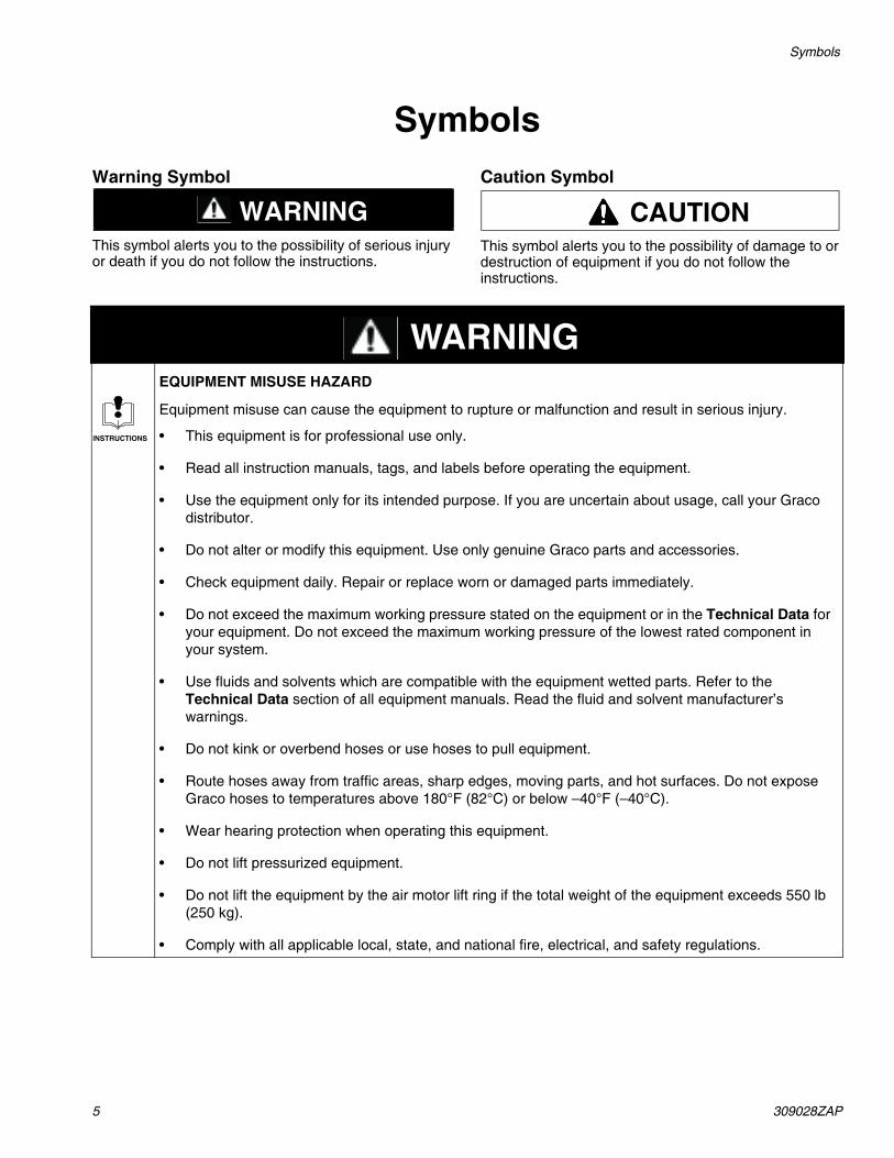
WARNINGWarning Symbol
This symbol alerts you to the possibility of serious injury or death if you do not follow the instructions.
CAUTIONCaution Symbol
This symbol alerts you to the possibility of damage to or destruction of equipment if you do not follow the instructions.
WARNINGEQUIPMENT MISUSE HAZARD
Equipment misuse can cause the equipment to rupture or malfunction and result in serious injury.
• This equipment is for professional use only.
• Read all instruction manuals, tags, and labels before operating the equipment.
• Use the equipment only for its intended purpose. If you are uncertain about usage, call your Graco distributor.
• Do not alter or modify this equipment. Use only genuine Graco parts and accessories.
• Check equipment daily. Repair or replace worn or damaged parts immediately.
• Do not exceed the maximum working pressure stated on the equipment or in the Technical Data for your equipment. Do not exceed the maximum working pressure of the lowest rated component in your system.
• Use fluids and solvents which are compatible with the equipment wetted parts. Refer to the Technical Data section of all equipment manuals. Read the fluid and solvent manufacturer’s warnings.
• Do not kink or overbend hoses or use hoses to pull equipment.
• Route hoses away from traffic areas, sharp edges, moving parts, and hot surfaces. Do not expose Graco hoses to temperatures above 180°F (82°C) or below –40°F (–40°C).
• Wear hearing protection when operating this equipment.
• Do not lift pressurized equipment.
• Do not lift the equipment by the air motor lift ring if the total weight of the equipment exceeds 550 lb (250 kg).
• Comply with all applicable local, state, and national fire, electrical, and safety regulations.
INSTRUCTIONS

309028ZAP 6
Symbols
WARNINGSKIN INJECTION HAZARD
Spray from the gun, hose leaks, or ruptured components can inject fluid into your body and cause extremely serious injury, including the need for amputation. Fluid splashed in the eyes or on the skin can also cause serious injury.
• Fluid injected into the skin might look like just a cut, but it is a serious injury. Get immediate surgical treatment.
• Do not point the gun at anyone or at any part of the body.
• Do not put your hand or fingers over the spray tip.
• Do not stop or deflect leaks with your hand, body, glove or rag.
• Do not “blow back” fluid; this is not an air spray system.
• Always have the tip guard and the trigger guard on the gun when spraying.
• Check the gun diffuser operation weekly. Refer to the gun manual.
• Be sure the gun trigger safety operates before spraying.
• Lock the gun trigger safety when you stop spraying.
• Follow the Pressure Relief Procedures on page 32 whenever you: are instructed to relieve pressure; stop spraying; clean, check, or service the equipment; and install or clean the spray tip.
• Tighten all fluid connections before operating the equipment.
• Check the hoses, tubes, and couplings daily. Replace worn, damaged, or loose parts immediately. Permanently coupled hoses cannot be repaired; replace the entire hose.
• Use only Graco approved hoses. Do not remove any spring guard that is used to help protect the hose from rupture caused by kinks or bends near the couplings.
MOVING PARTS HAZARD
Moving parts, such as the pump rod, follower plate and ram assembly, can pinch or amputate your fingers.
• Keep clear of all moving parts when starting or operating the pump.
• Keep your hands away from the follower plate and the lip of the drum while the ram is operating.
• Keep your hands away from the ram frame while the ram is operating.
• Before servicing the equipment, follow the Pressure Relief Procedures on page 32 to prevent the equipment from starting unexpectedly.

7 309028ZAP
Symbols
WARNINGFIRE AND EXPLOSION HAZARD
Improper grounding, poor ventilation, open flames or sparks can cause a hazardous condition and result in a fire or explosion and serious injury.
• Ground the equipment and the container where the material is deposited. Refer to Grounding the System on page 17.
• If there is any static sparking or you feel an electric shock while using this equipment, stop the pumps immediately. Do not use the equipment until you identify and correct the problem.
• Provide fresh air ventilation to avoid the buildup of flammable fumes from solvents or the fluid being sprayed.
• Keep the spray area free of debris, including solvent, rags, and gasoline.
• Electrically disconnect all equipment in the spray area.
• Extinguish all open flames or pilot lights in the spray area.
• Do not smoke in the spray area.
• Do not turn on or off any light switch in the spray area while operating or if fumes are present.
• Do not operate a gasoline engine in the spray area.
• Keep a fire extinguisher in the work area.
TOXIC FLUID HAZARD
Hazardous fluid or toxic fumes can cause serious injury or death if splashed in the eyes or on the skin, inhaled, or swallowed.
• Know the specific hazards of the fluid you are using.
• Store hazardous fluid in an approved container. Dispose of hazardous fluid according to all local, state and national guidelines.
• Always wear protective eyewear, gloves, clothing and respirator as recommended by the fluid and solvent manufacturer.

309028ZAP 8
Uncrating the System
Uncrating the SystemThe Uni-Drum supply system was carefully packaged forshipment by Graco. When the system arrives, performthe following procedure to uncrate the system.
To uncrate the system, do the following:
1. Inspect the crate carefully for shipping damage. Contact the carrier promptly if damage is discovered.
2. Remove the plywood sides and top of the crate.
3. Inspect the contents carefully. There should not be any loose or damaged parts.
4. Compare the packing slip against all items included in the crate. Report any shortages or other inspection problems immediately.
5. Remove the band straps that hold the Uni-Drum to the pallet.
NOTE: The Uni-Drum is ready for installation. Beforeinstalling the system, read the “General Description”section to become familiar with the system components.
OverviewInstallation OverviewThe location of the Uni-Drum should allow for easy loading and unloading of the 300 gallon (1200 liter) magnadrum or other tote drums with either a forklift truck or pallet-jack hand truck.
The Uni-Drum supply system must be leveled and mounted on a horizontal floor. An unleveled condition can keep the Uni-Drum from operating properly.
Anchor the frame’s four foot pads securely to the floor. The anchor bolts should be sized with sufficient safety factor to withstand the downward force of the follower plate and other objects that can push the frame off the floor.
Operation OverviewThe Uni-Drum is a supply system that evacuates fluids from a 300 gallon (1200 liter) magnadrum or other tote drums.
Each Uni-Drum includes two Graco air motors and displacement pumps, a ram assembly with a follower plate, a pneumatic layout panel that controls the air components and a junction box panel that connects with an electrical controller (supplied by the customer).
In short, the operator places the magnadrum inside the frame with the follower plate placed directly on top of the material. Locally, the system can be operated using pneumatic layout panel. Remotely, the system can be operated using signals through the junction box panel.
Two displacement pumps evacuate material out of each magnadrum. After removing the empty drum from the system, the operator repeats the evacuation process when another drum is ready for evacuation.
WARNINGEQUIPMENT MOVING HAZARDRemoving the unit off the pallet without following the uncrating procedure will damage the equipment.

9 309028ZAP
General Description
General DescriptionSystem ComponentsA general description of the Uni-Drum supply system helps the installers and operators become familiar with the system components. Contact your Graco distributor for help in choosing accessories to suit your particular needs.
Before you install the system you should be familiar with the parts described in the following paragraphs.
Fig. 1 shows the typical Uni-Drum supply system equipped with XL 10000™ air motors. The following list identifies the Uni-Drum system components:
Ref. Description
A Left hand (LH) supply unitB Right hand (RH) supply unitC Dura-Flo™ 1800 pumps with XL 10000™
air motors (2 units)D Ram assembly and follower plateE Main air inletF 3/8 npt air filterG Pneumatic layout panelH Junction box panelJ Drum lid holders
• Uni-Drum System (A) is usually setup to alternate the material supply operation between the left hand (LH) and right hand (RH) supply units, which is accomplished using a combination of robotic software programming (provided by others) and manual operators. Drum changeovers occur after the follower plate has reached its preset low limit level in the drum. Alternating between supply units eliminates the downtime that is usually expended unloading an empty drum and reloading a full drum.
– LH pump supply unit (A) accommodates one 300 gallon (1200 liter) drum. The LH supply unit has a local pneumatic layout panel and junction box panel.
– RH pump supply unit (B) accommodates one 300 gallon (1200 liter) drum. The RH supply unit has a local pneumatic layout panel and junction box panel.

309028ZAP 10
General Description
Fig. 1
Left Hand Models Right Hand Models246981 246982248306 248307249339 249340253676 253677258910 258911249152 249153249341 249342234972 234973258956 258957
C
D
F
H
C
H
G
E
G
E
H
J
D
F
H
A - Left Hand Unit B - Right Hand Unit

11 309028ZAP
General Description
Fig. 2
Left Hand Models Right Hand Models232729 232730
232839 232840
246921 246922
255666 255665
24H017 24H016
24U642 24U643
J
C
H
F
D
E
G
H
E
G
H
C
H
F
D
A - Left Hand Unit B - Right Hand Unit

309028ZAP 12
General Description
System Components (continued)
NOTE: The paragraphs that follow describe thecomponents for the LH pump supply unit only. Thedescriptions are the same for the RH pump supply unit.
• The two Dura-Flo™ 1800 Pumps (C) have XL 10000™ air motors. The pumps evacuate material from the drum.
• The follower plate (D) is connected to the ram assembly and is designed to apply an even amount of pressure to the material in the drum. With the follower plate in its raised position, the operator moves a drum inside the frame. The follower plate is lowered directly on top of the material in the drum. When pressure is applied to the follower plate, the material is pumped out of the drum through hoses, which are attached to the pump outlet ports. When the drum is empty, the operator raises the follower plate, removes the empty drum. The process is repeated when another drum is ready to be unloaded.
• 3/8 in. npt air filter (F) filters air to the pneumatic layout panel. The 5 micron filter removes particles, such as dust, moisture, foreign matter and other contaminants from the compressed air.
Pneumatic Layout Panel (G)
The pneumatic layout panel includes the following system components. For more information, refer to the Pneumatic Diagram on page 84.
• Main Air Inlet Valve (at E) is used to open or shutoff the air supply to the entire supply unit.
• Pump No. 1 Air Regulator controls pump speed and outlet pressure for pump no. 1 by adjusting the air pressure to the pump.
• Pump No. 1 Pressure Gauge displays the amount of air pressure supplied to pump no. 1.
• Pump No. 2 Air Regulator controls pump speed and outlet pressure for pump no. 2 by adjusting the air pressure to the pump.
• Pump No. 2 Pressure Gauge displays the amount of air pressure supplied to pump no. 2.
• Follower Vent Open Valve switch is activated to open the vent to relieve container pressure.
• Ram Up pushbutton turns on air pressure to raise the follower plate.
• The Ram Position Switch performs the following three functions:
– Place the switch in the RAISE position to raise the follower plate.
– Place the switch in the HOLD position to hold the follower plate in the current position.
– Place the switch in the LOWER position to lower the follower plate.
Junction Box Panel (H)The junction box panel includes the following system components. For additional information, refer to the Electrical Diagram on page 83.
• System Pressurized lamp is lit when air pressure is supplied to the system; the lamp is extinguished when the air supply is depressurized. This occurs after the Pump On button has been pushed and the pumps turned on.
• Pump Active lamp is lit when the air supply is turned on to the pumps; the lamp is extinguished when the pumps are inactive, thus turned off. This is activated by the Pump On pushbutton.
• Air Pressure On lamp is lit when air pressure to the system is turned on; the lamp is extinguished when air pressure to the system is shutoff.
• Ram Ready lamp is lit when the drum is in position; the lamp is extinguished when the drum is not in position.
• Pump Ready lamp is lit when the pumps are primed and ready for operation; the lamp is extinguished when the pumps are not ready for operation.
• Prime Pump pushbutton turns on the pumps, for priming. When the pumps are primed, the Pump Ready lamp turns on. The switch is not used when the Pump Ready lamp is lit. The Pump Active light will blink.
• Pump Reset pushbutton resets the pumps to an active state. When the pumps are reset, the Pump Active lamp turns off. The switch is not used when the Pump Active lamp is lit. The Pump Ready light is on.
• Pump On pushbutton turns the pumps on and off. When the pumps are turned on, the Pump Active lamp also turns on. When the pumps are turned off, the Pump Active lamp also turns off.
• Bulk Supply Depressurization button opens the depressurization valve to lower the fluid pressure.
• Auto Mode On/Off switch puts the system into or out of automatic operation.

13 309028ZAP
Installation
InstallationThe installation procedures in this section are intended toserve as a guide for installing the Uni-Drum system. Ifyou need more information, contact your Gracodistributor.
NOTE: When raising and lowering the follower plate, besure that the unit is unobstructed overhead to avoidinterference with other objects.
The installation procedure includes:
• Preparing the site
• Selecting a location for the Uni-Drum
• Preparing to install the Uni-Drum
• Installing the Uni-Drum
• Connecting power to the junction box
• Grounding the system
• Checking resistance between the junction box and the true earth ground
• Connecting air supply lines to Uni-Drum
Preparing the Site
Ensure that you have an adequate compressed air supply.Refer to the applicable instruction manual listed in RelatedPublications on page 3 to find the air consumption of yourpump. Approximately 450 cfm at 80 psi is required tooperate the pumps at the maximum rate.
Keep the site clear of any obstacles or debris that couldinterfere with the installer’s and operator’s movement.
Selecting a Location for the Uni-DrumRefer toTechnical Data on page 85 for ram mounting and clearance dimensions.
When selecting a location for the Uni-Drum, keep the following in mind:
1. There should be sufficient space for installing, servicing, and using the equipment.
• Select an accessible location for the system. There must be sufficient space around the system for maintenance.
• Select a convenient location for the equipment. Check that there is sufficient overhead clearance for the pump and ram when the ram is in the fully raised position. Make sure the air regulators for the pumps and follower plate are fully accessible.
• Make sure the air source for the PLC control panel and shutoff valves are fully accessible.
• Make sure there is easy and safe access to an appropriate pneumatic source. Graco recommends a minimum of 3 feet (0.91 m) of open space in front of the control panel.
2. Make sure that you will be able to level the base of the ram using metal shims.
Preparing to Install the SystemBefore installing the system:
• See component manuals for specific data on component requirements. Data presented here pertains to the system only.
• Have all system and subassembly documentation available during installation.
• Be sure that all non-Graco supplied hoses are adequately sized and pressure-rated to meet the system requirements.

309028ZAP 14
Installation
Installing the Uni-DrumTo install the Uni-Drum, follow the procedure below.Refer to Technical Data on page 85 for ram mountingand clearance dimensions.
1. Using equipment such as a forklift or handtruck, move the Uni-Drum into place on the floor. Remove the shipping pallet.
2. Level the Uni-Drum, using metal shims.
3. Using the holes in the base as a guide, drill holes for 13 mm (1/2 in.) anchors.
4. Bolt the Uni-Drum to the floor using anchors that are long enough to prevent the unit from tipping. Refer to page 86 for more information.
WARNINGEQUIPMENT MISUSE HAZARDThe Uni-Drum system is shipped with every major component already attached and weighs approx.
3950 lb (1792 kg). The Uni-Drum system should never be moved or lifted by one person. To prevent equipment damage or personal injury, engage an adequate number of personnel and use a forklift, hand truck, and sup- port devices, such as a hoist when moving and installing the Uni-Drum system.
CAUTIONBe sure to use as many people as needed when the frame is being lifted or moved. Exercise care to avoid jarring, dropping, or tilting the frame while it is being moved to its installed location to prevent injury or property damage.

15 309028ZAP
Installation
Connecting Power to the Junction BoxPerform the following procedure to connect the power to the junction box panel.
NOTE: Have a qualified electrician connect the junctionbox to a grounded electrical source that has the followingrequired service ratings:
To connect the junction box panel to the electricalsource, do the following:
1. Shut off system power at the main circuit breaker.
2. Remove the cover from the junction box panel.
3. Locate the PLC power terminals KS102 and KS100 on the terminal strip inside the junction box panel. See Fig. 3. For more information, refer to Electrical Diagram on page 83.
4. Using the upper wire duct on the left-hand side of the junction box panel, string two 14 AWG wires inside the box from the electrical power source.
5. Connect the two 14 AWG wires to power terminals KS102 (L1, hot) and KS100 (L2, neutral) in the junction box panel.
6. Seal the area where wires entered the junction box panel.
7. Replace the cover on the junction box panel.
WARNINGELECTRIC SHOCK HAZARDDo not connect the junction box panel to a power source unless you are a trained electrician. Failure to follow standard
procedures or to observe the necessary precautions could result in serious bodily injury or equipment damage.
CAUTIONIf power and grounding connections are not done properly, the equipment may be damaged and the warranty will be voided.
Description RequirementsVoltage: 120 Vac 24 Vdc
Hz: 50/60 -
Phase: 1 -
Circuit Breaker 5 Amp 5 Amp
WARNINGELECTROCUTION HAZARDInstalling and servicing this equipment requires access to parts which could cause an electric shock or other serious
injury. Have only qualified electricians access the control assembly.

309028ZAP 16
Installation
Fig. 3
Strain Relief
Fuse Blocks Terminals
Wire Way
Enclosure
Ground Lug
TI0205b
ISOLATION BLOCKS
(KNIFE SWITCH DISC.
KS100 10011002
KS102 10211022
(2) TOTAL Type1492 -WKD3TP
TerminalsSPARESPARESPARESPARESPARESPARESPARESPARESPARESPAREFU136FU143SUP136SUP144154115111481143114111361134112911271124112211191117111411121108110011001100110231003(31) TOTALType 0290.011.25ENTRELEC

17 309028ZAP
Installation
Grounding the System
1. Pump: use a ground wire and clamp. See Fig. 4. Verify that the ground screw (GS) is attached and tightened securely to the air motor. Connect the clamp (U) of the static ground cable (H) to a true earth ground. For a ground wire and clamp, order Part No. 244524.
Fig. 4
2. Air and fluid hoses: Use only electrically conductive hoses.
3. Air compressor: follow manufacturer’s recommendations.
4. Spray gun or dispensing valve: ground through connection to a properly grounded fluid hose and pump.
5. Object being sprayed: follow your local code.
6. Fluid supply drum: follow your local code.
7. Solvent pails used when flushing: follow your local code. Use only metal pails, which are conductive, placed on a grounded surface. Do not place the pail on a nonconductive surface, such as paper or cardboard, which interrupts the grounding continuity.
8. To maintain grounding continuity when flushing or relieving pressure, hold a metal part of the spray gun firmly to the side of a grounded metal pail, then trigger the gun.
Checking the Resistance Between the Pumps and the True Earth GroundHave a qualified electrician check the resistancebetween each pump and the true earth ground. If theresistance is greater than 1.0 ohms, a different groundsite may be required. Do not operate the system until theproblem is corrected.
NOTE: Use a meter that is capable of measuringresistance at this level.
WARNINGFIRE AND EXPLOSION HAZARD Before operating the pump, ground the system as explained below. Also read the section FIRE AND EXPLOSION HAZARD on page 7.
WARNINGFIRE, EXPLOSION, AND ELECTRIC SHOCK HAZARDTo reduce the risk of fire, explosion, or electric shock the resistance between the supply unit components and true earth ground must be less than 1.0 ohms

309028ZAP 18
Installation
Connecting the Air Supply Lines to the Uni-Drum
Perform the following procedure to connect the inputair supply lines to the Uni-Drum system.
Connecting Air Supply Lines to the Supply Units
To connect the main air supply line to the LH and RHsupply units, do the following:
NOTE: Have a qualified technician connect both supply units to an air supply source that has the following required ratings:
1. Check the air supply to ensure that it is properly sized and pressure-rated for this system.
2. Connect the air supply line to the 1 in. npt main air inlet
Fig. 5
WARNINGTo reduce the risk of overpressurizing your system, which could result in component rupture and cause serious injury, never exceed the specified maximum incoming air pressure to the pumps (see the Technical Data on page 85).
Description RequirementsInlet Port Size: 1 in. npt(f)
Air Volume: 450 cfm (maximum)
Input Air: 80 psi (5.5 bar, 0.55 MPa)
Main Air Inlet
Main Air Shutoff Valve
Air Line to Pneumatic Panel
Main Air Filter
Air Line to Pump Air Manifold
Pump Air Manifold
Pilot Valve
AirLIne Lubricator
Air Supply Lines to Pumps
TI0204
Ti20917a

19 309028ZAP
Installation
Connecting Output Hose to the PumpsThis procedure describes how to connect the fluid output hoses to the two pumps. It is the customer’s responsibility to have the fluid supply hose already installed and ready for connection to the pumps.
NOTE: For more information about the pumps, see Related Publications on page 3 for the pump instruction manuals.
NOTE: The fluid supply hose must move freely without kinking when the pumps move up and down.
Check the fluid supply hose to ensure it is properly sized and pressure-rated for this system. Use only electrically conductive hoses. The fluid supply hose should have spring guards on both ends. Connect the fluid supply hose to the fluid manifold outlet.
Fig. 6
CAUTIONThere must be a minimum of 10 feet (3 m) of fluid supply hose on the outlet to prevent damage to the unit.
Fluid Manifold
Fluid Outlet
Fluid Supply Hose
TI0139

309028ZAP 20
Operation
OperationThe operation procedures include:
• Prepare the operator
• Overview
• Junction box panel switches and indicators
• Pneumatic layout panel switches and indicators
• Initial system startup procedure
• Daily system startup
• System shutdown
• Operation modes for the pumps
• Pressure relief procedure
• Air motor icing
• Preventive maintenance schedule
• System operation procedures
Prepare the OperatorAll persons who operate the equipment must be trained in the safe, efficient operation of all system components as well as the proper handling of all fluids. All operators must thoroughly read all instruction manuals, tags, and labels before operating the equipment.
OverviewThe Uni-Drum supply system uses two air driven reciprocating pumps on the LH supply unit and two air driven reciprocating pumps on the RH supply unit. Each supply unit pumps material from a 300 gallon (1200 liter) drum.
General Functional Description
The LH and RH supply units can operate at the same time or as independent units. Generally, the Uni-Drum system is setup to operate as redundant units. This means that the RH unit is held in reserve on standby until the drum underneath the LH unit has been emp- tied, and vice versa.
Operating a redundant system allows the operator to maintain a continuous supply of material without interruption. The operator is afforded sufficient time to replace an empty drum at one supply unit while the drum at the other supply unit is being emptied.
System Startup
There are a series of steps that must be followed in sequential order to startup the system.
System Operation
Depending upon the system setup, at any time during operation, the operator can:
• Stop the pumps and relieve ram pressure at the LH supply unit.
• Stop the pumps and relieve ram pressure at the RH supply unit.
• Shutdown the system.
At the supply unit, the follower plate must be raised to load the drum into the supply unit. The follower plate is lowered by the operator directly into the drum. The pumps are turned on, the follower plate is pressurized, and material is pumped from the drum through the outlet ports on the pumps via a supply hose to one or more targeted applications.
Supply Unit Operation
The Uni-Drum supply system can be setup to alternate between the LH and RH supply units. This dual supply system setup (controlled by others) virtually eliminates material replenishment downtime.
The Uni-Drum supply system allows the operator to load the material drum into the RH supply unit while the LH supply unit drum is being emptied. When the supply unit changeover occurs, the operator unloads the empty drum at the LH supply unit while the RH supply unit drum is being emptied. The cycle is repeated as many times as needed.
System Shutdown
For system shutdown, the operator turns off the pumps and depressurizes the system. Depending upon the type of material, the operator may choose to raise the follower plate from the drum or keep the follower plate lowered in the drum to prevent the material from being contaminated. Some materials will harden or congeal when exposed to air or used past their shelf life. Material should be kept covered when it is not being used and uncovered when it is ready to use.

21 309028ZAP
Operation
Junction Box Panel Switches and IndicatorsUse the table and Fig. 7 when operating the switches and reading the indicator on the junction box panel.
Button/Switch What it DoesPRIME PUMP pushbutton • Primes both displacement pumps with material, making the
pumps ready to operate.
• Lights PUMP READY light.
PUMP RESET pushbutton • Restarts the pumps after the pumps were turned off.
• Lights PUMP ACTIVE light
PUMP ON pushbutton • Activates the pumps.
• Deactivates the pumps.
Bulk Supply Depressurizationpushbutton
• Opens the depressurization valve to lower the fluid supply pressure.
AUTO MODE ON/OFF switch • Places fluid dispensing system into Automatic or Manual mode.
Indicator Indicator Light is
Meaning
SYSTEMPRESSURIZED light
ON System is pressurized.
OFF System is depressurized.
PUMP ACTIVE light ON Pumps are active; air is available to the pumps.
OFF Pumps are inactive; air is unavailable to the pumps.
AIR PRESSURE ON light
ON Air pressure is available to the pumps for use.
OFF Air pressure is not available to the pumps for use.
RAM READY light ON Follower plate is ready for use.
OFF Follower plate is not ready for use.
PUMP READY light ON Pumps are primed and ready to use.
OFF Pumps are not ready to use.

309028ZAP 22
Operation
Junction Box Panel Switches and Indicators (continued)
Fig. 7
BULK SUPPLY DEPRESSURIZATION
SYSTEM PRESSURIZED
PUMP ACTIVE
AIR PRESS ON
RAM READY
PUMP RREADY
PRIME PUMP
PUMP RESET
PUMP ON
LOCAL REMOTE
MODEREMOTE
195320 and 119773 Panel Shown

23 309028ZAP
Operation
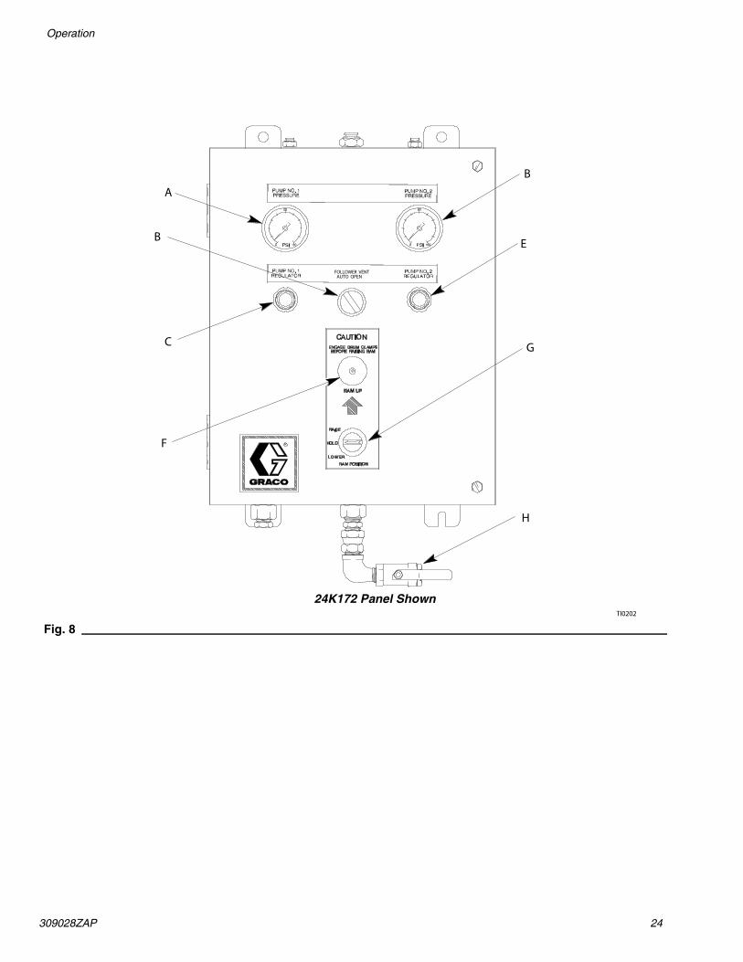
Pneumatic Layout Panel Switches and IndicatorsUse the table and Fig. 8 when operating the switches and reading the indicators on the pneumatic layout panel.
Ref Button/Switch/Gauge What it Does
A PUMP NO. 1 PRESSURE Air Gauge Indicates the air outlet pressure setting from pump no. 1.
B PUMP NO. 2 PRESSURE Air Gauge Indicates the air outlet pressure setting from pump no. 2.
C PUMP NO. 1 REGULATOR Control Knob Controls pump speed and outlet pressure by adjustingthe air pressure to pump no. 1.
D FOLLOWER VENT Directional Valve Opens and closes the vent that relieves air pressurefrom the follower plate assembly.
E PUMP NO. 2 REGULATOR Control Knob Controls pump speed and outlet pressure by adjustingthe air pressure to pump no. 2.
F RAM UP Pushbutton Raises the follower plate.
G RAM POSITIONSwitch
RAISE Allows the follower plate to raise.
HOLD Holds the follower plate in the current position.
LOWER Lowers the follower plate.
H Panel Air Inlet Valve Opens air supply line to the pneumatic layout panel.
309028ZAP 24
Operation
Fig. 8
A
B
C
B E
F
G
H
TI0202
FOLLOWER VENTAUTO OPEN
24K172 Panel Shown

25 309028ZAP
Operation
Flushing the System Before Initial Use
Flushing the system before its initial use can prevent material contamination, which may cause the material to fail or perform poorly.
To flush the system, perform the following procedure:
1. Select the material for the initial material load.
2. Verify whether the factory-test oil and the initial material load are compatible:
a. If the two substances are compatible, omit the remaining steps in this procedure and perform the Initial System Startup Procedure on page 26.
b. If the two substances are incompatible, perform the remaining steps in this procedure to flush the system.
3. Select a drum containing a compatible material that can dissolve, clean, and eliminate the factory test oil from the system. If necessary, check with the material supplier for a recommended flush material.
4. Before flushing, be sure the entire system and flushing drums are properly grounded. Refer to Grounding the System, on page 17.
5. Perform steps 9 through 15 of the Initial System Startup Procedure on page 26 to load the drum containing the solvent.
6. Run the flush material through the system for approximately 1 to 2 minutes.
7. Remove the drum containing the flush material.
Adjusting the Lid Holder Before Initial Use
1. Adjust the lower lid holder channel as low as it will go on the side of the ram post. The channel should be 1 in. (25 mm) higher from the floor in the front compared to the back.
2. Loosen the upper lid holder channel. place the lid in the center of the lower channel. Lower the upper channel until it contacts the lid. Tilt the rear of the upper channel down 1/2 to 1 in. (13 to 25 mm) and tighten all bolts.
3. The lid should roll in and out from the front and not roll out the rear.
CAUTIONFlush the system before performing the initial material loading procedure. The system was factory-tested using a light soluble oil, a soybean oil, or some other oil as tagged. Flush the system to avoid contaminating the material that has been designated for initial material loading.
WARNINGUse fluids and solvents that are chemically compatible with the equipment wetted parts. See the Technical Data sections of all the equipment manuals. Always read the material manufacturer’s literature before using fluid or solvent in this pump.

309028ZAP 26
Operation
Initial System Startup Procedure Settings for Initial System Startup
The initial system startup procedure contains the checklist of settings, adjustments, and procedural steps that must be completed before the system is ready for daily operation.
NOTE: Complete the startup procedure for the LH supply unit first. Then, repeat the startup procedure for the RH supply unit.
Perform the initial system startup procedure as follows:
1. Check all material hoses and fittings to ensure tightness and to prevent any material leakage.
2. Check all system air lines. Make sure that all routing of air lines will not interfere with any moving components within the system.
3. Fill the packing nut/wet cup on both pumps 1/3 full with Graco throat seal liquid (p/n 206995). Refer to instruction manual 308147 or 308148 for details.
4. Open the main air shut off valve, making air pressure available to the unit. See Fig. 5.
5. At the pneumatic layout panel (H), open the panel air inlet valve, making air pressure available to the pneumatic layout panel. See Fig. 5 and Fig. 8.
6. Adjust both pump main air regulators to 0 psi.
7. Follower Vent switch should be in AUTO position.
8. Set the RAM POSITION switch to RAISE.
9. Press the RAM UP valve switch to raise the follower plate above the height of the material drum to be used.
10. Set the RAM POSITION switch to HOLD.
WARNINGPRESSURIZED FLUID HAZARD To reduce the risk of serious bodily injury, such as fluid injection or splashing fluid in the eyes or on the skin, always wear eye protection and protective clothing when installing, operating, or servicing this dispensing system.
MOVING PARTS HAZARDMoving equipment parts can cause personal injury, including severing of hands or fingers. Make sure all personnel are clear of moving parts before operating the equipment
CAUTIONThe use of a non-compatible lubricant can cause material contamination or inadequate performance. Use only a lubricant compatible with the material to be pumped. Check with the material supplier for a recommended lubricant.
To help avoid damage to equipment, do not use a drum of material that has been dented or otherwise damaged; damage to the follower plate wiper may result.
WARNINGPRESSURIZED EQUIPMENT HAZARD To reduce risk of injury or equipment damage.
• Make sure all material hose connections are secure.
• Do not pressurize the system until you have verified the system is ready and it is safe to do so.

27 309028ZAP
Operation
Load Material
11. Roll a drum into the supply unit under the elevated follower plate.
NOTE: Whenever a drum change is required, remove the cover from the drum of new material by holding it level and lifting it straight up. Tipping the cover may allow accumulated dirt to spill into the drum, which may result in damage to the material and equipment.
12. IMPORTANT: Lubricate the follower plate wiper with a lubricant that is compatible with the material to be pumped. Check with your material supplier for compatibility.
NOTE: Before lowering the follower plate assembly into the drum, make sure that nothing is between the follower plate and the drum, or between the ram tie bar and the top of the ram posts.
13. Remove bleed sticks at the base of each pump.
14. Lower the follower plate as follows:
a. Set the Ram Position selector to LOWER.
b. Lower the follower plate until the material is evident in the bleedstick ports.
c. Set the Ram Position selector to HOLD.
d. Replace the bleedsticks.
e. Set the Ram Position selector to LOWER.
15. Close both pump #1 and pump #2 inlet valves (located on top of air motor).
16. To prime the pump, press the PRIME PUMP button.
17. Set the pump air pressure to 30 psi.
18. Check that the AIR PRESS. ON indicator is lit.
19. Use a catch device to bleed the pump. Slowly open Pump No. 1 bleeder valve. Back off the adjustment screw several turns; do not remove the screw.
20. Slowly open the bleed-type air valve to the air motor. Allow the pump to cycle slowly until all air escapes and material flows free of air from the bleeder valve.
21. Close the bleed-type air valve and pump bleeder valve.
22. Repeat these steps for Pump No. 2.
NOTE:
• If the pump does not prime properly, which may occur with heavier, high viscosity fluids, increase the air pressure to the ram.
• If fluid is forced out around the top wiper, ram pressure is too high; decrease the air pressure to the ram.
• Ram pressure adjustments may be carried out using the dual regulator inside the pneumatic panel, where the upper regulator knob controls the downward pressure of the ram, and the lower regulator knob controls the upward pressure of the ram.
23. After closing the bleed valve, return Pump No. 1 and 2 regulator to its normal pump pressure setting.
24. Open the air motor ball valves.
25. Open the ball valve in the outlet manifold from Pump No. 1 and 2.
26. Remove the waste containers, clean up any spilled material, and dispose of the waste material properly.
27. Press the PUMP RESET button to restore the system to operation.
28. Check that the following indicators are lit:
• SYSTEM PRESSURIZED
• AIR PRESS. ON
• RAM READY
• PUMP READY

309028ZAP 28
Operation
Adjusting the Pump Regulators
NOTE: Both pumps must operate at the same cycles per minute rate to prevent the occurrence of uneven drum evacuation.
NOTE: For the maximum air input pressure for each pump see the appropriate manual as indicated on the chart on page 2).
29. Run the system under normal conditions. Adjust the PUMP NO. 1 REGULATOR to the desired setting as follows:
a. Turn the knob clockwise to increase air pressure or counterclockwise to decrease air pressure (see Fig. 8).
b. Check the air gauge to verify the air pressure setting.
30. Repeat step 29 to adjust the air regulator for the PUMP NO. 2 REGULATOR.
Adjusting the Ram-Up and Ram-Down Regulators
31. At the pneumatic layout panel (see Fig. 7), open the hinged cover.
32. Set the RAM POSITION switch to RAISE and push the RAM UP pushbutton. Verify that the follower plate (5) elevates at the desired speed. If not, do the following:
a. Adjust the RAM –UP REGULATOR. Turn the knob clockwise to increase the amount of air pressure. Check the air gauge to verify that air pressure was increased. See Fig. 8.
b. Verify that regulator R3 is set to 5 to 10 psi (.035 to .07 MPa, 0.35 to 0.7 bar).
c. Repeat step 32.a until the ram raises at the desired speed.
33. Set the RAM POSITION switch to DOWN while observing the air gauge inside the panel.
34. Adjust the RAM – DOWN REGULATOR to 50 psi (0.34 MPa, 3.4 bar) as follows (see Fig. 8):
a. Turn the knob clockwise to increase air pressure or counterclockwise to decrease air pressure.
b. Check the air gauge to verify the air pressure setting.
35. Close and secure the hinged cover.
Preventing Pump Cavitation
NOTE: Cavitation occurs when the pump cylinder did not fully load with material on the upstroke, and a cavity forms in the material after the pump changes to the downstroke. Perform step 36 when there is pump cavitation. If cavitation is not occurring, omit step 36 and proceed to step 37.
36. To prevent cavitation from occurring, perform the following steps:
a. Press the PRIME PUMP switch to prime the pumps and fill the material passages.
b. Verify that the PUMP READY light turns on.
c. Lower the air motor air pressure until cavitation stops.
d. Increase the ram down pressure.
CAUTIONImproper setting of the Regulator R3 while the selector is in the HOLD position, can cause the plate to drop and operator injury. Failure to adjust the Regulator R3 properly can cause the platen to exit the drum at a high rate of speed, risking damage to the machine.

29 309028ZAP
Operation
Fig. 9
Ram DownRegulator
Ram Up
Regulator R3
Regulator
9327A
309028ZAP 30
Operation
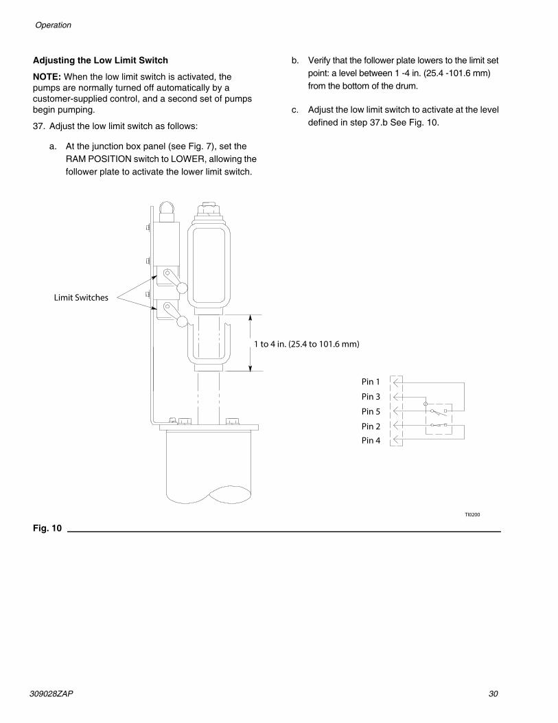
Adjusting the Low Limit Switch
NOTE: When the low limit switch is activated, the pumps are normally turned off automatically by a customer-supplied control, and a second set of pumps begin pumping.
37. Adjust the low limit switch as follows:
a. At the junction box panel (see Fig. 7), set the RAM POSITION switch to LOWER, allowing the follower plate to activate the lower limit switch.
b. Verify that the follower plate lowers to the limit set point: a level between 1 -4 in. (25.4 -101.6 mm) from the bottom of the drum.
c. Adjust the low limit switch to activate at the level defined in step 37.b See Fig. 10.
Fig. 10TI0200
1 to 4 in. (25.4 to 101.6 mm)
Limit Switches
Pin 1
Pin 3
Pin 5
Pin 2
Pin 4

31 309028ZAP
Operation
Daily System Startup
This procedure is normally provided by the integrator.
System Shutdown
This procedure is normally provided by the integrator.
Emergency Stop
When an emergency stop is required, do the following:
Stopping the System
1. To stop the system, close the main air shut off valve (see Fig. 11) to the supply unit.
Restarting the System2. To restart the system, do the following:
a. Open the main air shut off valve to the supply unit (see Fig. 11).
b. At the junction box panel, press the PUMP RESET switch which restarts the pumps after the pumps were turned off (refer to Fig. 7).
Fig. 11
Main Air Shut off Valve
Ti20917a
309028ZAP 32
Operation
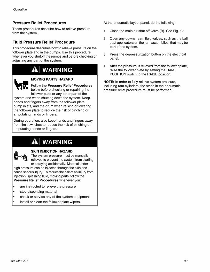
Pressure Relief ProceduresThese procedures describe how to relieve pressure from the system.
Fluid Pressure Relief ProcedureThis procedure describes how to relieve pressure on the follower plate and in the pumps. Use this procedure whenever you shutoff the pumps and before checking or adjusting any part of the system.
At the pneumatic layout panel, do the following:
1. Close the main air shut off valve (B). See Fig. 12.
2. Open any downstream fluid valves, such as the ball seat applicators on the ram assemblies, that may be part of the system.
3. Press the depressurization button on the electrical panel.
4. After the pressure is relieved from the follower plate, raise the follower plate by setting the RAM POSITION switch to the RAISE position.
NOTE: In order to fully relieve system pressure, including ram cylinders, the steps in the pneumatic pressure relief procedure must be performed.
WARNINGMOVING PARTS HAZARD
Follow the Pressure Relief Procedures below before checking or repairing the follower plate or any other part of the
system and when shutting down the system. Keep hands and fingers away from the follower plate, pump inlets, and the drum when raising or lowering the follower plate to reduce the risk of pinching or amputating hands or fingers.
During operation, also keep hands and fingers away from limit switches to reduce the risk of pinching or amputating hands or fingers.
WARNINGSKIN INJECTION HAZARD The system pressure must be manually relieved to prevent the system from starting or spraying accidentally. Material under
high pressure can be injected through the skin and cause serious injury. To reduce the risk of an injury from injection, splashing fluid, moving parts, follow the Pressure Relief Procedures whenever you:
• are instructed to relieve the pressure• stop dispensing material• check or service any of the system equipment• install or clean the follower plate wipers.

33 309028ZAP
Operation
Pneumatic Pressure Relief ProcedureThis procedure describes how to relieve pressure on the pneumatic panel and cylinders. Use this procedure whenever you perform ram assembly service on the piston rod seal or the ram piston.
1. Follow Fluid Pressure Relief Procedure, page 32.2. Fully lower the ram by setting the RAM POSITION
switch (A) to LOWER. Leave switch in LOWER position.
3. Open the door on the pneumatic control box (E).4. Adjust the air pressure to 0 PSI for the RAM DOWN
regulator. Refer to the gauge on the Ram Down Regulator (Fig. 11) and R3 Regulator to verify the ram has been depressurized.
5. Slowly open the drain cock located on the bottom of the air cylinders (D).
6. After the air pressure has been relieved, remove the RAM DOWN air line running from the top of the pneumatic control box to the ram cross bar (G).
7. Close the main air inlet on header (B).8. Leave the drain cock open and the RAM DOWN
airline removed until service is complete.9. After service is complete, close drain cocks and
make all pneumatic connections. Perform the Adjusting the Ram-Up and Ram-Down Regulators procedure, page 28.
Fig. 12
Fig. 13
WARNINGMOVING PARTS HAZARDFollow the Pressure Relief Procedure below before checking or repairing the follower plate or any other part of the
system and when shutting down the system. Keep hands and fingers away from the follower plate, pump inlets, and the drum when raising or lowering the follower plate to reduce the risk of pinching or amputating hands or fingers.
During operation, also keep hands and fingers away from limit switches to reduce the risk of pinching or amputating hands or fingers.
WARNINGSKIN INJECTION HAZARDThe system pressure must be manually relieved to prevent the system from starting or spraying accidentally. Material under
high pressure can be injected through the skin and cause serious injury. To reduce the risk of an injury from injection, splashing fluid, moving parts, follow the Pressure Relief Procedure whenever you:
• are instructed to relieve the pressure• stop dispensing material• check or service any of the system equipment• install or clean the follower plate wipers.
B
G
E
A
D

309028ZAP 34
Operation
Preventive Maintenance ScheduleThe operating conditions of your particular systemdetermine how often maintenance is required. Establisha preventive maintenance schedule by recording whenand what kind of maintenance is needed, and thendetermine a regular schedule for checking your system.
Changing Empty DrumsNOTE: After the automatic pump crossover has taken place, immediately replace the empty drum with a new, full drum. If both Uni-Drums become empty at the same time:
NOTE:
• Material will stop being delivered to the dispenser
• Air may enter the supply hose or pipe header
• Pump runaway could occur, resulting in damage to the pumps.
Drum Changing Procedure
To remove an empty drum and load a new, full drum:
1. Verify that the two front and rear drum clamps are engaged on the Uni-Drum ram base.
2. Check that the pump air is turned off. On the junction box panel the PUMP ACTIVE and PUMP READY indicators are not lit.
3. Check that the RAM UP air regulator is set to 60 psi (maximum).
4. Close the two ball valves at the outlet manifold at the rear of the Uni-Drums.
5. To raise the follower plate:
a. Set the RAM POSITION control to RAISE, then wait 5 seconds.
NOTE: If RAM UP button is pushed within 5 seconds, the vent valves may open before the pressure under the follower plate is relieved causing the material to bleed past the vents.
b. Push and hold the RAM UP button as the follower plate slowly rises.
6. With the ram raised and the RAM POSITION control set to RAISE, pull the drum clamps back and remove the empty drum, using a suitable lifting device.
7. IMPORTANT: Being careful not to damage the follower plate wipers, wipe or scrape any material buildup from the follower plate and wipers, and properly dispose of the waste material.
NOTE: When you open a new drum, take care to remove the cover by holding it level. Tipping the cover may allow accumulated dirt to spill into the material, which can damage the equipment. Also check that the drum is not damaged or dented.
8. Remove the cover from the new drum and remove any other packing from the drum, exposing the material. Make sure there are no foreign objects on the surface of the material.
9. Position the new drum, using a suitable lifting device, under the raised follower plate. Check that the RAM READY indicator is lit.
10. IMPORTANT: Lubricate the follower plate wipers with a lubricant approved by the material manufacturer.
11. Push the two front and rear drum clamps forward until engaged.
WARNINGMOVING PARTS HAZARDUse a long-handled flat-bladed ice scraper if it is necessary to scrape the bottom of the follower plate. Do not put your hands between the plate and the drum.
WARNINGPRESSURIZED FLUID HAZARD To reduce the risk of serious bodily injury, such as fluid injection or splashing fluid in the eyes or on the skin, always wear eye protection and protective clothing when installing, operating, or servicing this dispensing system.
MOVING PARTS HAZARDMoving equipment parts can cause personal injury, including severing of hands or fingers. Make sure all personnel are clear of moving parts before operating the equipment.

35 309028ZAP
Operation
12. Remove the bleed sticks from the follower plate.
NOTE: Before lowering the ram into the drum, make certain that nothing is between the follower plate and the drum, or between the ram tie bar and the top of the ram posts.
13. Lower the follower plate as follows:
a. Set the Ram Position selector to LOWER.
b. Lower the follower plate until the material is evident in the bleedstick ports.
c. Set the Ram Position selector to HOLD
d. Replace the bleedsticks.
e. Set the Ram Position selector to LOWER.
14. Close both pump #1 and pump #2 inlet valves (located on top of the air motor).
15. To prime the pump, press the PRIME PUMP button.
16. Set the pump air pressure to 30 psi.
17. Check that the AIR PRESS. ON indicator is lit.
18. Use a catch device to bleed the pump. Slowly open Pump No. 1 bleeder valve. Back off the adjustment screw several turns; do not remove the screw.
19. Slowly open the bleed-type air valve to the air motor. Allow the pump to cycle slowly until all air escapes and material flows free of air from the bleeder valve.
20. Close the bleed-type air valve and pump bleeder valve.
21. Repeat these steps for Pump No. 2.
NOTE:
• If the pump does not prime properly, which may occur with heavier, high viscosity fluids, increase the air pressure to the ram.
• If fluid is forced out around the top wiper, ram pressure is too high; decrease the air pressure to the ram.
• Ram pressure adjustments may be carried out using the dual regulator inside the pneumatic panel, where the upper regulator knob controls the downward pressure of the ram, and the lower regulator knob controls the upward pressure of the ram.
22. After closing the bleed valve, return Pump No. 1 and 2 regulator to its normal pump pressure setting.
23. Open the air motor ball valves.
24. Open the ball valve in the outlet manifold from Pump No. 1 and 2.
25. Remove the waste containers, clean up any spilled material, and dispose of the waste material properly.
26. Press the PUMP RESET button to restore the system to operation.
27. Check that the following indicators are lit:
• SYSTEM PRESSURIZED
• AIR PRESS. ON
• RAM READY
• PUMP READY
CAUTIONThe use of a non-compatible lubricant can cause material contamination or inadequate performance. Use only a lubricant compatible with the material to be pumped. Check with the material supplier for a recommended lubricant.To help avoid damage to equipment, do not use a drum of material that has been dented or otherwise damaged; damage to the follower plate wiper may result.
WARNINGPRESSURIZED EQUIPMENT HAZARDTo reduce risk of injury or equipment damage:
• Make sure all material hose connections are secure.
• Do not pressurize the system until you have verified the system is ready and it is safe to do so.

309028ZAP 36
Ram Assembly Troubleshooting
Ram Assembly Troubleshooting
Problem Cause(s) Solution(s)Ram won’t raise or lower Closed main air valve or clogged air line Open air valve, clear air line
Not enough air pressure Increase ram pressure
Worn or damaged piston Replace piston. See procedure on page 51.
Ram raises or lowers too fast Ram air pressure too high Decrease ram air pressure
Fluid squeezes past follower plate wipers
Ram air pressure too high Decrease ram air pressure
Worn or damaged wipers Replace wipers. See procedure on page 54.
Pump won’t prime properly, or pumps air
Not enough ram air pressure Increase ram pressure
Worn or damaged ram piston Replace ram piston. See procedure on page 51.
Bent drum has stopped follower plate Replace drum

37 309028ZAP
Pump Troubleshooting
Pump TroubleshootingFor additional information about the displacement pump, refer to Related Publications on page 3 to find the applicable instruction manual.
Problem Cause(s) Solution(s)Rapid downstroke or upstroke(pump cavitation)
Air is trapped in pump. Bleed air from the pump using this procedure:
1. Place a waste container under the pump bleed port.
2. Press the PRIME PUMP button to turn on air to the pump.
3. Allow material to flow from the bleed port until it is air-free.
4. Release the PRIME PUMP button to shut off air to the pump. Close the bleed port.
5. Turn air on to the pump and set the pump air regulator for normal operation.
Downstroke: Lower check in pump is worn.
Upstroke: Upper check in pump is worn.
Rebuild and replace pump, as necessary.
Material leaks around pump outlet Outlet fitting is loose. Tighten outlet fitting.
Material leaks around bleed port Bleed port fitting is loose. Tighten bleed port fitting.
Pump won’t move up or down Problem with air motor. See Air Motor Troubleshooting chart on page 38.
Foreign object lodged in pump. Remove object and rebuild pumpassembly.
To reduce the risk of serious injury whenever you are instructed to relieve pressure, always follow the Pressure Relief Procedures (page 32).Before attempting to dislodge a foreign object:
1. Relieve system pressure.
2. Remove the pump from the air motor.
Wet-cup leaks Worn throat packings. Tighten wetcup. Replace throat packings.
WARNING

309028ZAP 38
Air Motor Troubleshooting
Air Motor TroubleshootingFor additional information about the air motor, refer to Related Publications on page 3 to find the applicableinstruction manual.
Problem Cause(s) Solution(s)Air motor will not shift directions, stalled in DOWN position
Main air valve spool is dirty or damaged Clean/rebuild main air valve.
Air motor will not shift directions, stalled in UP position
Air motor stalled halfway between the top and bottom
Air continually exhausting around air motor shaft.
Air motor shaft seal is damaged Replace air motor shaft seal.
Air continually exhausting around the air valve/slide valve
Air valve/slide valve gasket is damaged Replace the valve gasket.
Air continually exhausting from muffler while the motor is idle
Internal seal damage Rebuild air motor.
Oil leaking from exhaust port Too much lubricant mixed in with the air supply
Reduce lubricant supply.
Frost build-up on muffler Air motor operating at high pressure, or high cycle rate
Reduce pressure, cycle rate, or duty cycle of the air motor.

39 309028ZAP
Junction Box Panel Troubleshooting
Junction Box Panel Troubleshooting
Pneumatic Layout Panel Troubleshooting
Problem Cause(s) Solution(s)Power from PLC control panel is ON, but no indicator lights are lit at junction box panel.
The knife switch disconnect contacts (KS100 and KS102) are open.
Check the PLC power connections at customer’s site.
One or more fuses blown. Replace the blown fuse(s). Check FU136 and FU143 located inside the knife switch disconnect blocks.
Voltage limit to circuits in junction box panel was exceeded.
Check the surge suppressors SUP136 and SUP144. Replace if required. Reset power to unit.
Problem Cause(s) Solution(s)
Ram will not move up or down. Main air valve on box is not open.
Air supply to unit is not on.
Open valve.
Turn on air supply.Ram will not move up. Direction valve is not in the UP position.
RAM UP button is not pushed.
Resistance in drum is too great.
Insufficient lubrication of the follower plate seal.
Set direction valve to the UP position.
Push RAM UP button.
Turn air pressure up to 60 psi. The ram may take a few minutes to withdraw from the container.
After the plate has been removedfrom the container, clean the seal
Pumps will not operate. Air regulator is set too low. Increase air pressure setting.
Vent valve will not open. FOLLOWER VENT switch is not in AUTO position.
Put FOLLOWER VENT switch in AUTO position.

309028ZAP 40
Routine Maintenance
Routine MaintenanceFlushing the System
Flush the pump:
• Before the first use
• When changing material or fluid part number or brand
• Before fluid can dry or settle out in a dormant pump (check the shelf life or pot life of catalyzed fluids)
• Before storing the pump.
Flush with a fluid that is compatible with the fluid you are pumping and with the wetted parts in your system. Check with your fluid manufacturer or supplier for recommended flushing fluids and flushing frequency.
To flush the system, perform the following procedure:
1. Place a drum of compatible flush material under the follower plate.
2. Run the pumps and circulate the flush material through the system for approximately 1 to 2 minutes or until the solution is clean.
3. Remove the drum containing the flush material from under the follower plate.
4. Return the system to current readiness condition.
Cleaning the System
To clean the system, perform the following procedure:
1. IMPORTANT: Being careful not to damage the follower plate wipers, wipe or scrape any material buildup from the follower plate and wipers, and properly dispose of the waste material.
2. Apply a generous amount of lubricant to the follower plate wipers.
3. To clean vent valve:
a. Put FOLLOWER VENT switch to ON position. This opens valve to allow you to clean out dried material.
b. When vent is clean, put switch to AUTO position.
4. Return the system to current readiness condition.
Wiper LubricationIt is extremely important that the follower plate wipers be thoroughly lubricated between drum changes. The follower plate may stick without lubrication.
WARNINGFIRE AND EXPLOSION HAZARD Before flushing, read the section FIRE AND EXPLOSION HAZARD on page 7. Be sure the entire system and flushing pails are properly grounded. Refer to Grounding the System on page 17.
CAUTIONCleaning the system after using it can prevent material contamination, which may cause the material to fail or perform poorly. Do not load new material into a contaminated system.
Clean the system to avoid untimely equipment malfunctions and to ensure that system components operate efficiently
WARNINGMOVING PARTS HAZARDUse a long-handled flat-bladed ice scraper if it is necessary to scrape the bottom of the follower plate. Do not put your hands between the plate and the drum.
41 309028ZAP
Junction Box Panel Service
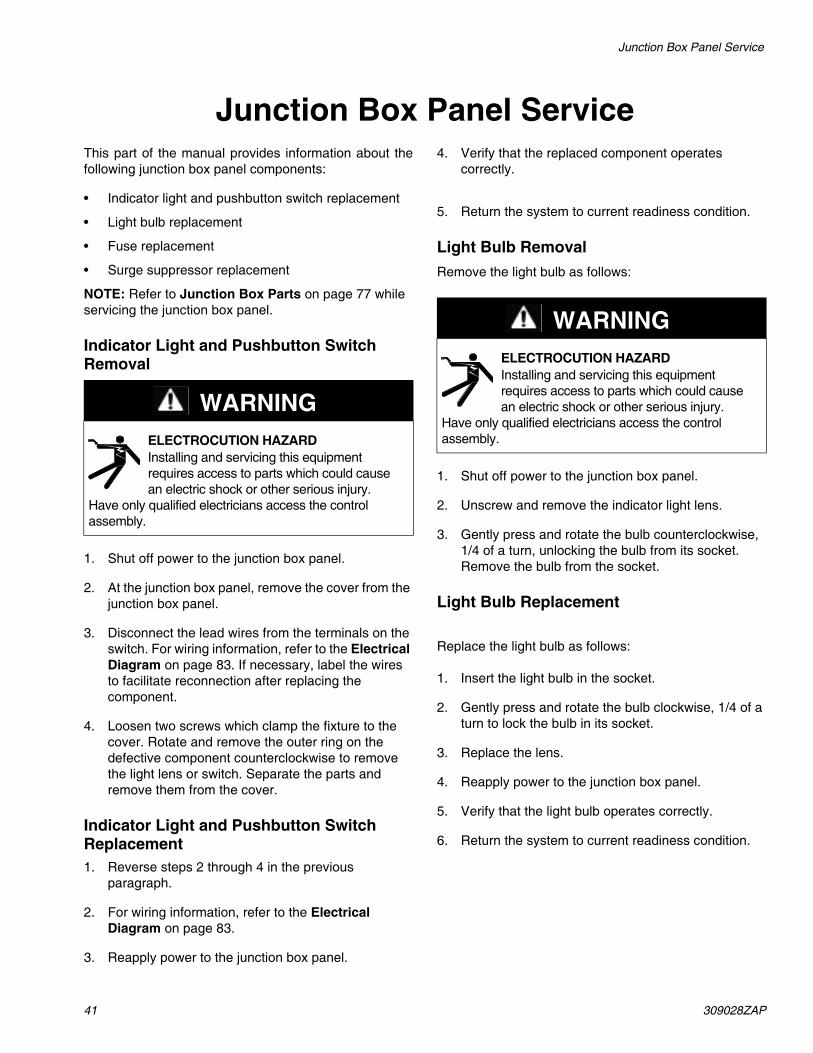
Junction Box Panel ServiceThis part of the manual provides information about thefollowing junction box panel components:
• Indicator light and pushbutton switch replacement
• Light bulb replacement
• Fuse replacement
• Surge suppressor replacement
NOTE: Refer to Junction Box Parts on page 77 while servicing the junction box panel.
Indicator Light and Pushbutton Switch Removal
1. Shut off power to the junction box panel.
2. At the junction box panel, remove the cover from the junction box panel.
3. Disconnect the lead wires from the terminals on the switch. For wiring information, refer to the Electrical Diagram on page 83. If necessary, label the wires to facilitate reconnection after replacing the component.
4. Loosen two screws which clamp the fixture to the cover. Rotate and remove the outer ring on the defective component counterclockwise to remove the light lens or switch. Separate the parts and remove them from the cover.
Indicator Light and Pushbutton Switch Replacement1. Reverse steps 2 through 4 in the previous
paragraph.
2. For wiring information, refer to the Electrical Diagram on page 83.
3. Reapply power to the junction box panel.
4. Verify that the replaced component operates correctly.
5. Return the system to current readiness condition.
Light Bulb RemovalRemove the light bulb as follows:
1. Shut off power to the junction box panel.
2. Unscrew and remove the indicator light lens.
3. Gently press and rotate the bulb counterclockwise, 1/4 of a turn, unlocking the bulb from its socket. Remove the bulb from the socket.
Light Bulb Replacement
Replace the light bulb as follows:
1. Insert the light bulb in the socket.
2. Gently press and rotate the bulb clockwise, 1/4 of a turn to lock the bulb in its socket.
3. Replace the lens.
4. Reapply power to the junction box panel.
5. Verify that the light bulb operates correctly.
6. Return the system to current readiness condition.
WARNINGELECTROCUTION HAZARD Installing and servicing this equipment requires access to parts which could cause an electric shock or other serious injury.
Have only qualified electricians access the control assembly.
WARNINGELECTROCUTION HAZARD Installing and servicing this equipment requires access to parts which could cause an electric shock or other serious injury.
Have only qualified electricians access the control assembly.

309028ZAP 42
Junction Box Panel Service
Fig. 14
Fuses Terminals
Wire Way
Enclosure
Ground Lug
TI0205b
Ground Surge Suppressors
KS100 10011002
KS102 10211022
(2) TOTAL Type1492 -WKD3TP
TerminalsSPARESPARESPARESPARESPARESPARESPARESPARESPARESPAREFU136FU143SUP136SUP144154115111481143114111361134112911271124112211191117111411121108110011001100110231003(31) TOTALType 0290.011.25ENTRELEC
43 309028ZAP
Junction Box Panel Service
Fuse Removal
Remove the fuse as follows:
1. Shut off power to the junction box panel.
2. At the junction box panel, remove the cover from the junction box panel.
3. Locate the failed fuse on the terminal strip. Reference Fig. 14 for the fuse terminal identification.
4. Carefully remove the fuse from the fuse holder.
Fuse Replacement
Replace the fuse as follows:
NOTE: Check the new fuse to ensure that it matches the amp rating of the failed fuse.
1. Press both ends of the new fuse evenly into place in the fuse holder. See Fig. 14.
2. Reinstall the cover on the junction box panel.
3. Reapply power to the junction box panel.
4. Verify that the fuse operates correctly.
5. Return the system to current readiness condition.
WARNINGELECTROCUTION HAZARD Installing and servicing this equipment requires access to parts which could cause an electric shock or other serious injury.
Have only qualified electricians access the control assembly.
309028ZAP 44
Surge Suppressor Removal
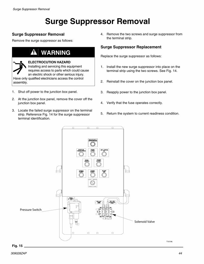
Surge Suppressor RemovalSurge Suppressor RemovalRemove the surge suppressor as follows:
1. Shut off power to the junction box panel.
2. At the junction box panel, remove the cover off the junction box panel.
3. Locate the failed surge suppressor on the terminal strip. Reference Fig. 14 for the surge suppressor terminal identification.
4. Remove the two screws and surge suppressor from the terminal strip.
Surge Suppressor Replacement
Replace the surge suppressor as follows:
1. Install the new surge suppressor into place on the terminal strip using the two screws. See Fig. 14.
2. Reinstall the cover on the junction box panel.
3. Reapply power to the junction box panel.
4. Verify that the fuse operates correctly.
5. Return the system to current readiness condition.
Fig. 15
WARNINGELECTROCUTION HAZARD Installing and servicing this equipment requires access to parts which could cause an electric shock or other serious injury.
Have only qualified electricians access the control assembly.
T10196
Pressure Switch
Solenoid Valve

45 309028ZAP
PLC Interface Accessory Kit Service
PLC Interface Accessory Kit ServiceThis part of the manual provides information about thefollowing PLC interface accessory kit components:
• Valve assembly bank replacement
• Pressure switch assembly replacement
Valve Assembly Bank ReplacementRemove the valve assembly bank that is mounted below the junction box panel as follows:
NOTE: The valve assembly bank has two solenoids (SOL139 and SOL147) that are used as switches to control pump operation. SOL139 depressurizes the pumps. If the output is high (open), pumps will depressurize. SOL147 turns air on to the pumps.
1. Shut off power to the junction box panel.
Valve Assembly Removal
2. At the junction box panel, remove the cover off the junction box panel.
3. Locate the valve assembly (203) that is attached to the mounting plate (201) below the junction box panel (217). See Fig. 15.
4. Disconnect the two cables (216) from the terminal strip inside the junction box panel (217) for the valve assembly (203) bank. For wiring information, refer to the Electrical Diagram on page 83.
5. Remove four cap screws (205), the lock washers (206), and the valve assembly (203) from the mounting plate (201).
Valve Assembly Replacement
6. Install the new valve assembly (203) on the mounting plate (201) using the four cap screws (205) and lock washers (206). See Fig. 15.
7. Reconnect the two cables (216) on the terminal strip inside the junction box panel (217) for the valve assembly (203) bank. For wiring information, refer to the Electrical Diagram on page 83.
8. Reinstall the cover on the junction box panel.
9. Reapply power to the junction box panel.
10. Perform the Daily System Startup procedure on page 31 at the applicable supply unit (LH or RH).
11. Verify that the valve assembly (203) bank operates correctly.
12. Return the system to current readiness condition.
WARNINGELECTROCUTION HAZARD Installing and servicing this equipment requires access to parts which could cause an electric shock or other serious injury.
Have only qualified electricians access the control assembly.

309028ZAP 46
PLC Interface Accessory Kit Service
Pressure Switch Assembly Replacement
Remove the pressure switch assembly that is mounted below the junction box panel as follows:
NOTE: The pressure switch (PS108) turns air pressure on the system.
1. Shut off power to the junction box panel.
Switch Removal
2. Remove the cover from the junction box panel.
3. Locate the pressure switch assembly (202) that is attached to the mounting plate (201) below the junction box panel (217). See Fig. 15.
4. Disconnect the 5-pin cord (211) from the pressure switch assembly (202). For wiring information, refer to the Electrical Diagram on page 83.
5. Disconnect the end of the lead wire from the pressure switch assembly (202). Leave the other end of the lead wire connected to the valve assembly bank (203).
6. Remove the two cap screws, the lock washers, and the pressure switch assembly (202) from the mounting plate (201).
Switch Replacement
To replace the switch, follow the switch removal steps in reverse order.
WARNINGELECTROCUTION HAZARD Installing and servicing this equipment requires access to parts which could cause an electric shock or other serious injury.
Have only qualified electricians access the control assembly.

47 309028ZAP
PLC Interface Accessory Kit Service
Fig. 16TI0208
Junction Box Panel
Mounting Plate
Pressure Switch Assembly
90° Elbow
Tube Fitting Muffler
Elbow
Screw, Washer
Valve Assembly
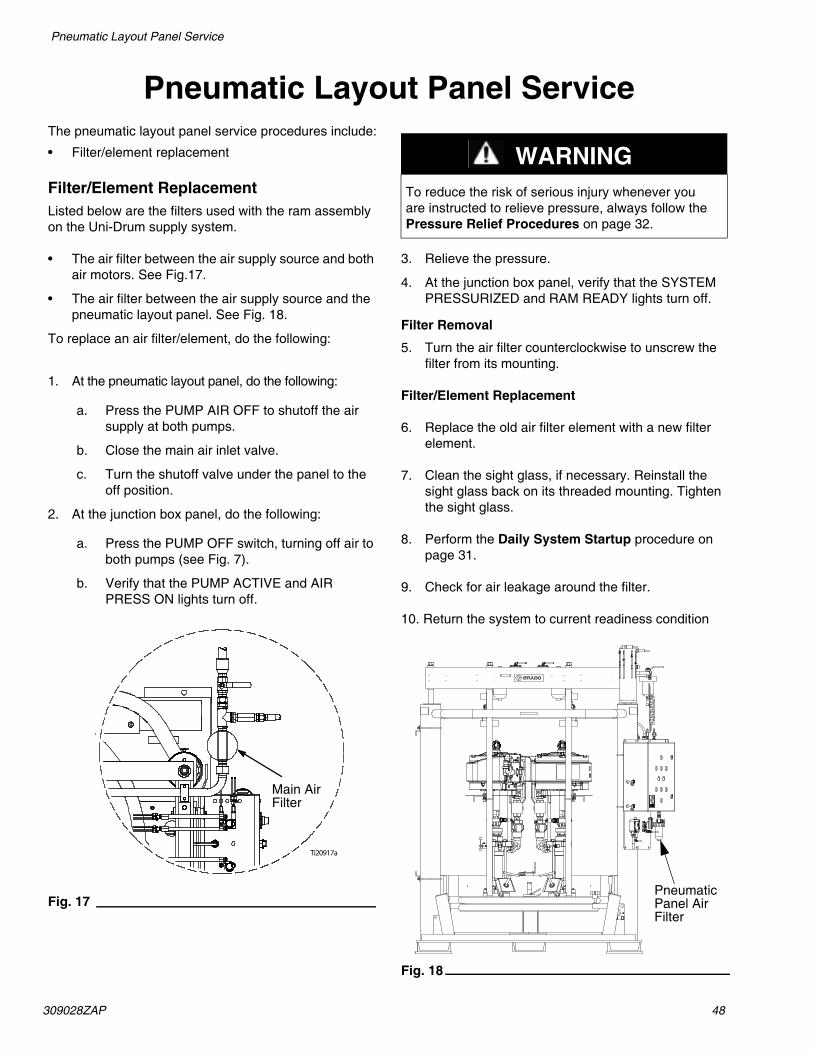
309028ZAP 48
Pneumatic Layout Panel Service
Pneumatic Layout Panel ServiceThe pneumatic layout panel service procedures include:
• Filter/element replacement
Filter/Element ReplacementListed below are the filters used with the ram assembly on the Uni-Drum supply system.
• The air filter between the air supply source and both air motors. See Fig.17.
• The air filter between the air supply source and the pneumatic layout panel. See Fig. 18.
To replace an air filter/element, do the following:
1. At the pneumatic layout panel, do the following:
a. Press the PUMP AIR OFF to shutoff the air supply at both pumps.
b. Close the main air inlet valve.
c. Turn the shutoff valve under the panel to the off position.
2. At the junction box panel, do the following:
a. Press the PUMP OFF switch, turning off air to both pumps (see Fig. 7).
b. Verify that the PUMP ACTIVE and AIR PRESS ON lights turn off.
Fig. 17
3. Relieve the pressure.
4. At the junction box panel, verify that the SYSTEM PRESSURIZED and RAM READY lights turn off.
Filter Removal
5. Turn the air filter counterclockwise to unscrew the filter from its mounting.
Filter/Element Replacement
6. Replace the old air filter element with a new filter element.
7. Clean the sight glass, if necessary. Reinstall the sight glass back on its threaded mounting. Tighten the sight glass.
8. Perform the Daily System Startup procedure on page 31.
9. Check for air leakage around the filter.
10. Return the system to current readiness condition
Fig. 18
Ti20917a
Main Air Filter
WARNINGTo reduce the risk of serious injury whenever you are instructed to relieve pressure, always follow the Pressure Relief Procedures on page 32.
Pneumatic Panel Air Filter

49 309028ZAP
Pneumatic Layout Panel Service
Fig. 19
TI0202
FOLLOWER VENTAUTO OPEN
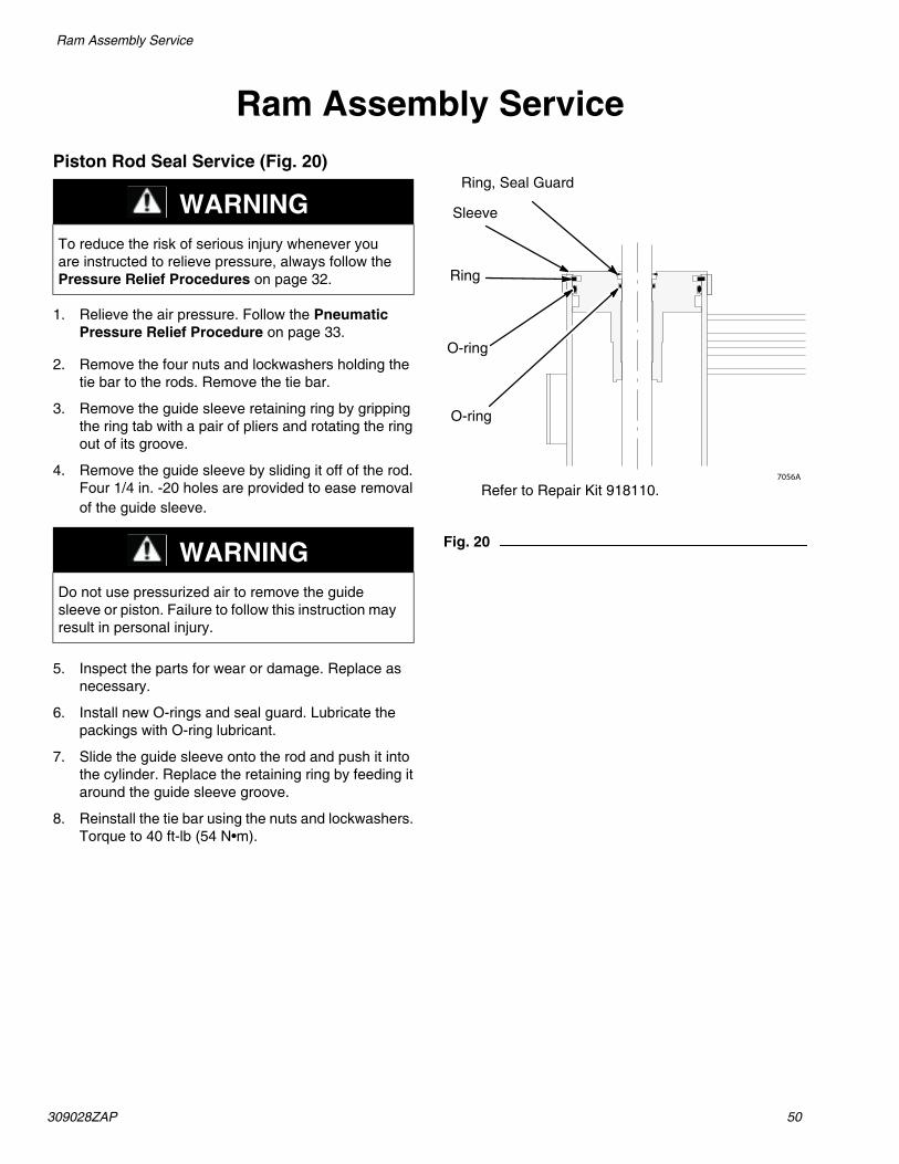
309028ZAP 50
Ram Assembly Service
Ram Assembly ServicePiston Rod Seal Service (Fig. 20)
1. Relieve the air pressure. Follow the Pneumatic Pressure Relief Procedure on page 33.
2. Remove the four nuts and lockwashers holding the tie bar to the rods. Remove the tie bar.
3. Remove the guide sleeve retaining ring by gripping the ring tab with a pair of pliers and rotating the ring out of its groove.
4. Remove the guide sleeve by sliding it off of the rod. Four 1/4 in. -20 holes are provided to ease removal of the guide sleeve.
5. Inspect the parts for wear or damage. Replace as necessary.
6. Install new O-rings and seal guard. Lubricate the packings with O-ring lubricant.
7. Slide the guide sleeve onto the rod and push it into the cylinder. Replace the retaining ring by feeding it around the guide sleeve groove.
8. Reinstall the tie bar using the nuts and lockwashers. Torque to 40 ft-lb (54 N•m).
Fig. 20
WARNINGTo reduce the risk of serious injury whenever you are instructed to relieve pressure, always follow the Pressure Relief Procedures on page 32.
WARNINGDo not use pressurized air to remove the guide sleeve or piston. Failure to follow this instruction may result in personal injury.
7056A
Ring, Seal Guard
Sleeve
Ring
O-ring
O-ring
Refer to Repair Kit 918110.

51 309028ZAP
Ram Assembly Service
Ram Piston Service (Fig. 21)
1. Relieve the air pressure. Follow the Pneumatic Pressure Relief Procedure on page 33.
2. Remove the tie bar as explained under Piston Rod Seal Service (Fig. 20).
3. Remove the guide sleeve and slide it off of the piston rod.
4. Carefully pull the piston rod straight up out of the cylinder. If the rod is cocked to one side, the piston or inside surfaces of the cylinder could be damaged.
5. Carefully lay the piston and rod down so the rod will not be damaged or bent. Remove the lower piston retaining ring. Slide the piston off the piston rod.
6. Install new O-ring seals on the piston rod and the piston. Lubricate the piston and seals. Reinstall the piston and retaining ring.
7. Carefully insert the piston into the cylinder and push the rod straight down into the cylinder. Add 3 ounces of lubricant to each cylinder after inserting the piston.
8. Slide the guide sleeve onto the piston rod. Reinstall the retaining ring and tie bar, as explained under Piston Rod Seal Service (Fig. 20).
Fig. 21
WARNINGTo reduce the risk of serious injury, whenever you are instructed to relieve pressure, always follow the Pressure Relief Procedures on page 32.
WARNINGDo not use pressurized air to remove the guide sleeve or piston. Failure to follow this instruction may result in personal injury.
7056A
Band
PistonRing
O-ring
O-ring
Ring
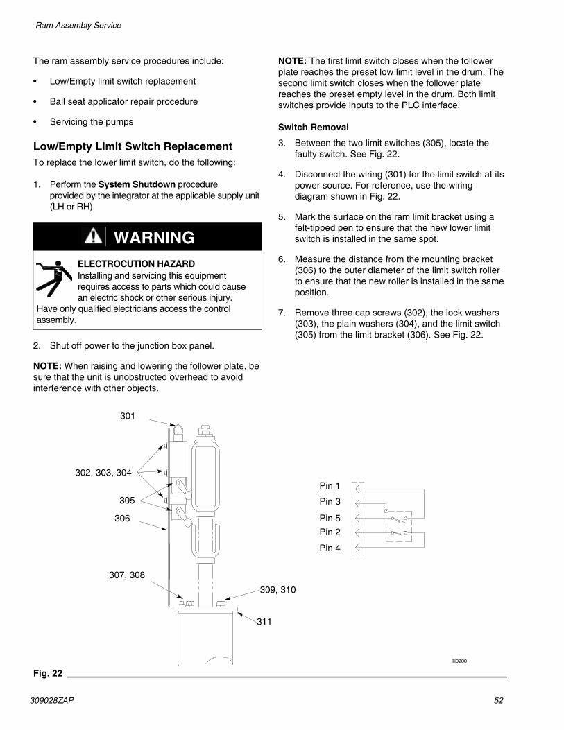
309028ZAP 52
Ram Assembly Service
The ram assembly service procedures include:
• Low/Empty limit switch replacement
• Ball seat applicator repair procedure
• Servicing the pumps
Low/Empty Limit Switch ReplacementTo replace the lower limit switch, do the following:
1. Perform the System Shutdown procedure provided by the integrator at the applicable supply unit (LH or RH).
2. Shut off power to the junction box panel.
NOTE: When raising and lowering the follower plate, be sure that the unit is unobstructed overhead to avoid interference with other objects.
NOTE: The first limit switch closes when the follower plate reaches the preset low limit level in the drum. The second limit switch closes when the follower plate reaches the preset empty level in the drum. Both limit switches provide inputs to the PLC interface.
Switch Removal
3. Between the two limit switches (305), locate the faulty switch. See Fig. 22.
4. Disconnect the wiring (301) for the limit switch at its power source. For reference, use the wiring diagram shown in Fig. 22.
5. Mark the surface on the ram limit bracket using a felt-tipped pen to ensure that the new lower limit switch is installed in the same spot.
6. Measure the distance from the mounting bracket (306) to the outer diameter of the limit switch roller to ensure that the new roller is installed in the same position.
7. Remove three cap screws (302), the lock washers (303), the plain washers (304), and the limit switch (305) from the limit bracket (306). See Fig. 22.
Fig. 22
WARNINGELECTROCUTION HAZARD Installing and servicing this equipment requires access to parts which could cause an electric shock or other serious injury.
Have only qualified electricians access the control assembly.
TI0200
301
302, 303, 304
305
307, 308
306
Pin 1
Pin 3
Pin 5Pin 2
Pin 4
309, 310
311

53 309028ZAP
Ram Assembly Service
Switch Replacement
8. Install the new limit switch (305) on the limit bracket (306) using the three cap screws (302), lock washers (303), and plain washers (304). See Fig. 22.
9. Reconnect the wiring (301) for the limit switch at its power source. For reference, use the wiring diagram shown in Fig. 22.
10. Make sure that the limit switch roller is positioned in the same location per the measurement in step 6. See Fig. 22.
11. Reinstall the cover on the junction box panel.
12. Reapply power to the junction box panel.
13. Perform the Daily System Startup procedure provided by the integrator at the applicable supply unit (LH or RH).
14. Verify that the limit switch operates correctly.
15. Return the system to current readiness condition.
Depressurization Valve (Ball Seat Applicator) Repair Procedure
Refer to instruction manual 3A1792 for the ball seat applicator (V1M350) service procedures and parts information.
Servicing the Pumps
When the pumps and air motors require service, refer to the applicable instruction manual, listed below, for detailed information.
Form Description P/N308147 Carbon Steel Dura-Flo™
Pump 1800 with XL 10000™ Air Motor
237555
308148 Stainless Steel Dura-Flo™ Pump 1800 with XL 10000™ Air Motor
241957
308213 XL 10000™ Air Motor 24X856

309028ZAP 54
Ram Assembly Service
Replacing Wipers (Fig. 23)1. Perform the System Shutdown procedure provided
by the integrator.
2. To replace worn or damaged wipers (412), raise the follower plate up out of the drum. Remove the drum from the base. Wipe the fluid off the follower plate. Refer to the Changing Empty Drums procedure on page 34.
3. Separate the wiper joint (A) and bend back the strapping (413a) covering the clamp setscrew (413c). See Detail A of Fig. 23. Loosen the setscrew, pull the end of the strapping through the clamp (413b) and remove the wiper.
4. Slide the strapping (413a) through the new wiper (412). Slide the clamp (413b) onto the new strapping and bend the strapping back approximately 3 in. (76 mm). Insert the strapping through the clamp a second time. See Detail B of Fig. 23.
5. Install the wipers on the follower plate. Position the wipers so that their joints (A) are 180° apart.
NOTE: You will need the special banding tool (C) shown in Detail C of Fig. 23 to tighten the strapping. Order Part No. 168092 Banding Tool.
6. Grip the strapping (413a) with the tool (C) as shown. With your thumb on the gripper lever (E), turn the tool handle (F) clockwise to apply tension.
NOTE: Be careful not to pull the cutting handle (D) until you are ready to cut the strapping in step 8.
7. Continue turning the tool handle until you see the strapping stop moving through the clamp (413b). Stop turning the handle.
8. Tighten the setscrew (B) with a wrench (G). Pull the cutting handle (D) to cut. Remove the tool (C). Bend the strapping back over the clamp (413b).
9. Pound the wiper all the way around with a rubber mallet until the joints (A) are butted tightly together.
10. Return the system to current readiness condition. Refer to the Changing Empty Drums procedure on page 34.
Fig. 23
05712
1
3
2
0294602949
E
F413a
D
C
G
413c
413b
A
413a
412 413b 413aH
413c413b412
1
2
2
Slide the clamp onto the strapping and bend the strapping back approximately 3 in. (76 mm).
Turn clockwise to apply tension.
Cut the strapping and bend it back over the clamp.
Detail A
Detail C
Detail B
55 309028ZAP
Ram Assembly Service
Pump Removal(Refer to System Parts Diagram; page 56.)
1. Relieve the air pressure from the air motors and ram assembly to be serviced.
2. Move the RAM POSITION switch to HOLD.
3. Close the pump outlet ball valves and relieve the fluid pressure from the pumps at the pump bleed valve on the ram assembly to be serviced.
4. Using an overhead lifting device, attach and secure a chain capable of lifting the weight of the pump assembly to the eye at the top of the air motor.
NOTE: For effective pump removal, the lifting point must be directly above the pump and capable of moving sideways. The lifting action should be the “chain fall” type that allows a slow upward and downward movement.
NOTE: Check the Technical Data page in the separate pump manual to find the weight of the pump being serviced. For example, Graco XL 10000™ 45:1 SST Pump (24Y208) weighs 236 lb (106 kg) per Form 308148.
5. Detach the air hose from the air motor.
6. Detach the fluid supply hose at the pump outlet.
NOTE: When loosening the pump and the air motor fasteners in steps and below, ensure the chain slack is taken up to prevent the pump assembly from falling.
7. On the follower plate adapter, loosen and rotate or remove four lugs and hex bolts holding the flange of the pump lower.
8. On the underside of the air motor, remove the bolts securing the air motor to the motor support brackets. It may be necessary to move or remove some brackets for effective pump removal.
9. Detach any other connections to the pump assembly to ensure the pump is free of attachments before removal. Possible connections include:
• Air motor exhaust kit
• Pump proximity switch kit
• Pump grounding wire
NOTE: When lifting the pump in step below, ensure the lifting chain does not damage the air controls mounted at the top of the ram cross-members.
10. Using a “chain fall” style lifting device, slowly pull the pump upward a few inches until the base of the pump clears the pump mounting adapter and the air motor clears the support brackets.
11. Pull the pump assembly out of the ram assembly and guide the pump assembly downward to the floor, placing the base of the pump on a wood surface and taking care not to damage the seal area of the pump inlet housing.
12. Remove the gasket and o-ring (items 32 and 33) from the pump adapter. They should be discarded and replaced when the pump is reinstalled.
13. Clean excess and hardened material from the pump adapter on the follower plate.
14. Ensure that material is not rising through the pump adapter in the follower plate. If material is flowing upward, move the RAM POSITION switch to RAISE until the flow stops, then move the switch back to HOLD.
15. Move the pump assembly to a suitable work area and repair the pump using the appropriate Graco Instruction Manual.
Pump Installation(Refer to System Parts Diagram; page 56.)
1. When the pump is serviced and tested and ready to be replaced in the Uni-Drum Ram, perform the steps of the Pump Removal procedure in reverse order.
2. It is recommended that the pump be tagged with the type and date of repair and the name of the technician who performed the repair.
3. Before returning the reassembled pump to production use, it must be primed with material and air removed from the material. Follow the Pump Instruction Form and the pump material bleeding procedure from the Changing Empty Drums section on page 34.
WARNINGTo reduce the risk of serious injury, whenever you are instructed to relieve pressure, always follow the Pressure Relief Procedures on page 32.

309028ZAP 56
Parts
Parts246981, 248306, 249339, 253676, 258910 - 47:1 Left Hand Supply Unit
246982, 248307, 249340, 253677, 258911 - 47:1 Right Hand Supply Unit
249152, 249341, 234972, 258956 - 35:1 Left Hand Supply Unit
249153, 249342, 234973, 258957 - 35:1 Right Hand Supply Unit
46
68
7071
76
6626
121
11967, 72
26
7
15
93, 9497
27
2646
99, 100101
98
1435, 48
17
47
34
1
5, 9, 49
80
33
52
649, 31
1179, 41, 48, 49
13
38
16
60
30
See detail F
Detail F

57 309028ZAP
Parts
19
10
116 10
20
110 96 95
2553
114113
14, 73, 74
86
87
73, 115
123 112 111122
24
Detail C
See detail C

309028ZAP 58
Parts
Ref PartNo. No. Description Qty
RefNo.
PartNo.1 241902 ELEVATOR, assembly 300 gallon 1 Description Qty
3 C58306 PLATE, adjuster 2 29 C12039 HOSE, air 14 C58361 BRACKET, support 2 30 C19032 UNION, swivel 35 C20450 U-BOLT 4 31 111803 SCREW, cap, hex 86 196073 CLAMP 8 33 109495 O-RING 27 15D133 CLAMP, support 4 34 115438 VALVE, ball 18 517272 CLAMP, support 2 35 109570 WASHER 89 100132 WASHER, flat 12 36 214656 HOSE, coupled, 10 ft. 110 C12509 TUBE, nylon 64 ft. 37 C19381 ELBOW, tube, (m) 111 195319 PANEL, pneumatic layout 1 38 054139 TUBE, nylon 412 158585 NIPPLE 2 39 C19200 WASHER 413 24Y227 PUMP, 47:1 stainless steel 1 40 C19124 SCREW, cap, hex 4
(248306, 248307, 249339, 249340, 41 C19126 SCREW, cap, hex 4253676, 253677 only) 42 517254 CLIP, tube 3
24Y228 PUMP, 47:1 stainless steel 1 43 110299 RIVET, blind 3(246981, 248982, 258910, 258911 only) 44 106149 FILTER, air, 1/2 npt 1
24Y192 PUMP, 35:1 stainless steel 1 45 521975 UNION, pipe 2(249152, 249153, 249341, 249342, 234963 UNION, pipe (234972, 234973, 2234972, 234973, 258956, 258957 only) 253676, 253677, 258910, 258911,
14 C51238 U-BOLT 6 258956, 258957 only)15 101566 NUT, lock 6 46 118854 VALVE, ball 416 517288 TUBE, coiled 2 47 24Y228 PUMP, 47:1 stainless steel 117 241844 BRACKET, mounting 2 (248306, 248307, 249339, 249340,18 C38457 COUPLING, reducing 2 253676, 253677 only)19 106464 TEE, pipe 2 24Y227 PUMP, 47:1 stainless steel 120 C20463 NIPPLE, reducing, hex 3 (246981, 248982, 258910, 258911 only)21 C57799 VALVE, check 1/2 in. 1 24Y206 PUMP, 35:1 stainless steel 122 C19019 UNION, swivel 3 (249152, 249153, 249341, 249342,23 C38324 ELBOW, street 2 234972, 234973, 258956, 258957 only)
119900 ELBOW, street (234972, 234973, 2 48 100307 NUT, hex 12253676, 253677, 258910, 258911, 49 100133 WASHER, lock 20258956, 258957 nly) 50 617200 BRACKET, support 1
24 196085 COVER, left 1 52 112698 SWIVEL, elbow (m) 425 C20811 SCREW, socket head, flat 12 53 196084 COVER, right 126 C20490 NIPPLE, hex 7 54 C52751 PLATE, limit switch 1
119893 NIPPLE, hex (234972, 234973, 7 55 C19810 SCREW, cap 2253676, 253677, 258910, 258911, 56 195454 BRACKET, limit 1258956, 258957 only) 57 C19197 WASHER 4
27 246929 VALVE, check 2 58 C19204 WASHER, lock 4234960 VALVE, check (234972, 234973,
253676, 253677, 258910, 258911, 258956, 258957 only)
259 C20003 SCREW, cap 4
Continued on next page.

59 309028ZAP
Parts
Ref Part Ref PartNo. No. Description Qty No. No. Description Qty60 C07431 CONNECTOR, sealed 2 79 114158 ADAPTER, fitting 161 104227 NUT, lock 2 80 195356 KIT, accessory 162 C19138 SCREW, cap, hex 2 81 158555 NIPPLE, reducing 263 100016 WASHER, lock 6 82 113332 VALVE, ball 264 100018 WASHER, lock spring 2 83 112859 FILTER, air 165 C07560 SWITCH, limit, with arm 2 84 501014 ACTUATOR, air 266 15D140 MANIFOLD, three-way 1 85 104172 FITTING, 1/8NPT x 1/4 tube 4
(249341, 249342, 249152, 249153, 86 113532 FITTING, elbow, female 4248306, 248307, 249339, 249340, 87 617202 MANIFOLD, air bracket 1246981, 246982 only) 88 617337 COLLAR, clamp 4
15G091 MANIFOLD, three-way 1 89 C19800 SCREW, cap, socket head 4(234972, 234973, 258910, 258911, 90 617338 BRACKET, mounting 2258956, 258957, 253676, 253677 only) 91 517455 SWITCH 2
67 C19491 TEE, fitting, 1-1/4 npt(f) 1 92 C56572 CABLE 2119901 TEE, fitting, 1-1/4 npt(f) 1 93 196510 COUPLING, housing 2
(234972, 234973, 258910, 258911, 94 119417 SCREW 2258956, 258957, 253676, 253677 only) 95 516102 CLAMP, pipe 1
68 V1M350 APPLICATOR, ball seat, 1/2 in. 1 96 114508 NIPPLE 169 C20485 NIPPLE, hex 1 97 233041 PLATE, ram, Neoprene 4
114373 NIPPLE, hex (234972, 234973, 3 98 617180 ROD, connecting 8253676, 253677, 258910, 258911, 99 101535 NUT 8258956, 258957, 253676, 253677 only) 100 101533 WASHER, spring lock 1
70 156172 COUPLING, hex pipe 1 101 617204 CARRIAGE, weldment, 300 gallon 215G092 COUPLING, hex pipe 1 102 100549 ELBOW, street 2
(234972, 234973, 253676, 253677, 103 C20461 NIPPLE, reducing, hex 2258910, 258911, 258956, 258957 only) 104 515147 REGULATOR, air, 1/2p 2
71 234558 HOSE, coupled 1 107 115419 ADAPTER, fitting 2234962 HOSE, coupled (234972, 234973, 1 108 214849 LUBRICATOR 2
253676, 253677, 258910, 258911, 109 517290 HOSE 2258956, 258957 only) 110 C19438 ELBOW, fitting, 90° 1
72 C19661 FITTING, 1-1/4 x 1/2 in. 1 111 16U204 TUBE, unidrum, air inlet 1119896 FITTING, 1-1/4 x 1/2 in. 1 112 114112 CONNECTOR, fitting (f) 2
(234972, 234973, 253676, 253677, 113 113093 CONNECTOR, pipe 2258910, 258911, 258956, 258957 only) 114 C20378 BRANCH, fitting 2
73 C19213 WASHER, lock 10 115 100469 SCREW, cap, hex 274 C19185 NUT, jam hex 4 116 502526 VALVE, air three-way 276 234428 HOSE, coupled 2 117 246994 VALVE, pressure, bleed 1
234961 HOSE, coupled (234972, 234973, 2 118 120163 KIT, safety, lockout (not shown) 1253676, 253677, 258910, 258911, (234972, 234973, 258956, 258957 only) 253676, 253677 only)
77 243255 KIT, accessory, PLC interface 1 119 C20487 NIPPLE, hex, 3/4-14 npt 1(246981, 246982, 248306, 120 206996 FLUID, TSL, 1 gal 1248307, 249152, 249153, 234972, 121 617569 FITTING, reducer, plug-in 2234973, 253676, 253677 only) 122 15D936 FITTING, male connector,
24V775 KIT, accessory, PLC interface 1 1/2 npt x 5/8-12 2(249339, 249340, 249341, 123 16U212 CLAMP, 1.25 in. OD pipe 1249342, 258910, 258911, 258956, 124 94/0398/99 FITTING, 90°, 1” NPT 2258957 only) 130 103347 VALVE, safety, 100 psi 2
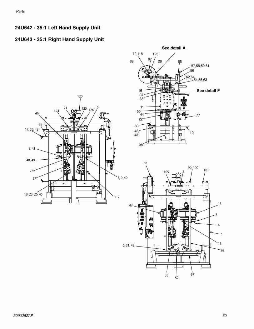
309028ZAP 60
Parts
24U642 - 35:1 Left Hand Supply Unit
24U643 - 35:1 Right Hand Supply Unit
99, 100105
9752
33
6, 31, 49
60
47
4
3
13
1012
98
15
1
48, 49
76
27
18, 23, 26, 45
5, 9, 49
117
71124
46
1417, 35, 48
9, 41
5126125
120See detail F
See detail A
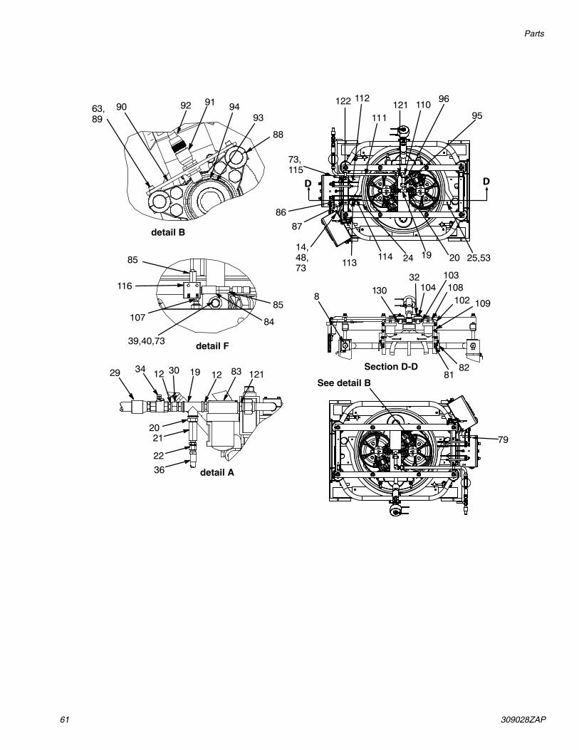
61 309028ZAP
Parts
DD
detail B
detail F
detail A
See detail B
Section D-D

309028ZAP 62
Parts
Ref Part Ref PartNo. No. Description Qty No. No. Description Qty
29 C12039 HOSE, air 11 241902 ELEVATOR, assembly 300 gallon 1 30 C19032 UNION, swivel 33 C58306 PLATE, adjuster 2 31 111803 SCREW, cap, hex 84 C58361 BRACKET, support 2 33 109495 O-RING 25 C20450 U-BOLT 4 34 115438 VALVE, ball 16 196073 CLAMP 8 35 109570 WASHER 87 15D133 CLAMP, support 4 36 214656 HOSE, coupled, 10 ft. 18 517272 CLAMP, support 2 37 C19381 ELBOW, tube, (m) 19 100132 WASHER, flat 12 38 054139 TUBE, nylon 410 C12509 TUBE, nylon 64 ft. 39 C19200 WASHER 411 195319 PANEL, pneumatic layout 1 40 C19124 SCREW, cap, hex 412 158585 NIPPLE 2 41 C19126 SCREW, cap, hex 413 24Y192 PUMP, 35:1 stainless steel 1 42 517254 CLIP, tube 314 C51238 U-BOLT 6 43 110299 RIVET, blind 315 101566 NUT, lock 6 44 106149 FILTER, air, 1/2 npt 116 517288 TUBE, coiled 2 45 234963 UNION, pipe, sst 217 241844 BRACKET, mounting 2 46 118854 VALVE, ball 418 119899 COUPLING, reducing, sst 2 47 24Y206 PUMP, 35:1 stainless steel 119 106464 TEE, pipe 2 48 100307 NUT, hex 1220 C20463 NIPPLE, reducing, hex 3 49 100133 WASHER, lock 2021 C57799 VALVE, check 1/2 in. 1 50 617200 BRACKET, support 122 C19019 UNION, swivel 3 52 112698 SWIVEL, elbow (m) 423 119900 ELBOW, street, sst 2 53 196084 COVER, right 124 196085 COVER, left 1 54 C52751 PLATE, limit switch 125 C20811 SCREW, socket head, flat 12 55 C19810 SCREW, cap 226 119893 NIPPLE, hex, sst 7 56 195454 BRACKET, limit 127 234960 VALVE, check, sst 2 57 C19197 WASHER 4
58 C19204 WASHER, lock 459 C20003 SCREW, cap 4
Continued on next page.

63 309028ZAP
Parts
Ref Part 94 119417 SCREW 2No. No. Description Qty 95 516102 CLAMP, pipe 1
96 114508 NIPPLE 160 C07431 CONNECTOR, sealed 2 97 233041 PLATE, ram, Neoprene 461 104227 NUT, lock 2 98 617180 ROD, connecting 862 C19138 SCREW, cap, hex 2 99 101535 NUT 863 100016 WASHER, lock 6 100 101533 WASHER, spring lock 164 100018 WASHER, lock spring 2 101 617204 CARRIAGE, weldment, 300 gallon 265 C07560 SWITCH, limit, with arm 2 102 100549 ELBOW, street 266 94/0398/99 FITTING, 90°, 1” NPT 2 103 C20461 NIPPLE, reducing, hex 267 119901 TEE, fitting, 1-1/4 npt(f), sst 1 104 515147 REGULATOR, air, 1/2p 268 V1M350 APPLICATOR, ball seat, 3/4 in. 1 107 115419 ADAPTER, fitting 269 114373 NIPPLE, hex, sst 3 108 214849 LUBRICATOR 271 24U667 HOSE, coupled, sst 1 109 517290 HOSE 272 127119 BUSHING, reducing, sst 1 110 C19438 ELBOW, fitting, 90° 173 C19213 WASHER, lock 10 111 16U204 TUBE, unidrum, air inlet 176 24U666 HOSE, coupled, sst 2 112 114112 CONNECTOR, fitting (f) 277 24V775 KIT, accessory, PLC interface 1 113 113093 CONNECTOR, pipe 279 114158 ADAPTER, fitting 1 114 C20378 BRANCH, fitting 280 195356 KIT, accessory 1 115 100469 SCREW, cap, hex 281 158555 NIPPLE, reducing 2 116 502526 VALVE, air three-way 282 113332 VALVE, ball 2 117 246994 VALVE, pressure, bleed 183 112859 FILTER, air 1 118 190724 NIPPLE, hex, sst 184 501014 ACTUATOR, air 2 120 206996 FLUID, TSL, 1 gal 185 104172 FITTING, 1/8NPT x 1/4 tube 4 121 617569 FITTING, reducer, plug-in 286 113532 FITTING, elbow, female 4 122 15D936 FITTING, male connector,87 617202 MANIFOLD, air bracket 1 1/2 npt x 5/8-12 288 617337 COLLAR, clamp 4 123 16U212 CLAMP, 1.25 in. OD pipe 189 C19800 SCREW, cap, socket head 4 124 617203 BAR, support 190 617338 BRACKET, mounting 2 125 517284 MANIFOLD, y-pipe 191 517455 SWITCH 2 126 C20449 BOLT, U 292 C56572 CABLE 2 127 16F241 FITTING, adapter 193 196510 COUPLING, housing 2 130 103347 VALVE, safety, 100 psi 2

309028ZAP 64
Parts
232729, 47:1 Left Hand Supply Unit, with carbon steel pump232839, 47:1 Left Hand Supply Unit, with stainless steel and ceramic pump232730, 47:1 Right Hand Supply Unit, with carbon steel pump (shown)232840, 47:1 Right Hand Supply Unit, with stainless steel and ceramic pump246921, 47:1 Right Hand Supply Unit, with stainless steel pump246922, 47:1 Left Hand Supply Unit, with stainless steel pump255666, 47:1 Left Hand Supply Unit, with carbon steel pump255665, 47:1 Right Hand Supply Unit, with carbon steel pump
GRACOR
AUTO MODE
OFF ON
BULK SUPPLYDEPRESSURIZATION
LT103 LT104
B A B
EA
P
EB
A
EA
EB
P
PB202PB201PB200
G G
LT102LT100
G
LT101
G G

65 309028ZAP
Parts
* Not Shown
Ref Part Ref PartNo. No. Description Qty No. No. Description Qty1 241902 ELEVATOR, assembly 300 gallon; 1 20 C20463 NIPPLE, fitting hex reducing; 1 in. 1
see page 82 21 C57799 VALVE, check; 1/2 npt (fbe) 12 241891 FOLLOWER PLATE ASSY; 1 22 C19019 FITTING, union, swivel 2
(232729, 232839, 246921, 255666 24 196085 COVER, left 1 only) 25 C20811 SCREW, socket, flat head 12
243510 see page 73 26 C20490 FITTING, nipple, hex 2(232730, 232840, 246922, 255665 29 C12039 HOSE, air; 1 in. ID 1 only) 30 C19032 SWIVEL, adapter, union 3
3 C58360 PLATE, adjuster, Uni-Drum 2 31 111803 SCREW, cap, hex head 84 C58361 BRACKET, pump support 2 32 184086 GASKET 25 C20450 U-BOLT 4 33 109495 O-RING 16 196073 CLAMP 8 34 115438 VALVE, ball; 1 in. locking 17 241837 KIT, accessory, pneumatic; 1 35 109570 WASHER, plain 8
see page 69 36 214656 HOSE; 1/2 in ID; 10 ft long 28 C19126 SCREW, cap hex head 4 39 243488 KIT, accessory; see page 71 29 100132 WASHER, flat 16 40 100133 LOCKWASHER, spring; 3/8 in. 2010 101566 NUT, lock 6 41 C38457 COUPLING, reducing 211 100307 NUT, hex; 3/8-16 12 42 521850 VALVE, check 212 158585 NIPPLE 1 43 C38324 ELBOW, street 213 24Y211 PUMP, 47:1; carbon steel; 2 44 233058 HOSE, coupled 2
(232729, 232730, 255665, 45 521975 UNION, pipe 2255666 only; see manual 308147) 46 118854 VALVE, ball 2
24Y221 PUMP, 47:1; stainless steel and 2 47 24Y212 PUMP, 47:1; carbon steel; 1ceramic (232729, 232730, 255665,(232839, 232840 only; 255666 only; see manual 308147)see manual 308148) 24Y222 PUMP, 47:1; stainless steel and 1
24Y225 PUMP, 47:1; stainless steel; 2 ceramic;(246921, 246922 only; (232839, 232840 only;see manual 308148) see manual 308148)
14 C51238 U-BOLT; 6 in. tube x 1/2-13un 4 24Y226 PUMP, 47:1; stainless steel; 115 241838 KIT, accessory, PLC interface; 1 (246922, 246921 only;
see page 78 see manual 308148)(232729, 232730, 232839, 49 101535 NUT, hex; 7/8 in. 4232840 only) 50 101533 LOCKWASHER, spring; 7/8 in. 4
24V775 KIT, accessory, PLC interface; 1 52 112698 ELBOW, swivel; 1/8 npt 4see page 78 53 196084 COVER, right 1(255665, 255666 only) 54* 103347 VALVE, safety, 100 psi 2
16 241840 KIT, accessory, depressurization; 1 56 94/0398/99 FITTING, 90°, 1” NPT 2see page 68
17 241844 BRACKET, mounting 219 106464 TEE, pipe; 1 in. npt 1

309028ZAP 66
Parts
Ref PartNo. No. Description Qty
The following items are for 255665, 255666, only. Items are not shown.
60 C07431 CONNECTOR, sealed 261 104227 NUT, lock 262 C07560 SWITCH, limit with arm 263 100018 WASHER, lock, spring 264 C19138 SCREW, cap, hex head 265 100016 WASHER, lock 666 C19810 SCREW, cap, socket head 267 195454 BRACKET, limit 168 C19197 WASHER, plain 469 C19204 WASHER, lock #10 470 C20003 SCREW, cap, socket head 471 C52751 PLATE, limit switch 172 104172 FITTING, limit switch 473 501014 ACTUATOR, air 274 502526 VALVE, air, 3-way 275 115419 FITTING, adapter 277 C19185 NUT, jam, hex 478 C19213 WASHER, lock 479 114158 FITTING, adapter, Y 180 C12509 TUBE, nylon 12 ft81 195356 KIT, accessory 1

67 309028ZAP
Parts
Part No. 241840, Depressurization Kit
RefNo.
PartNo.
RefNo.
Part No.Description Qty Description Qty
16c V1M350 APPLICATOR, ball seat; 1 16g 617569 FITTING, reducer, plug-in 2see 3A1792 for parts 16h 236425 HOSE 1
16d C20490 NIPPLE 1 16k 157129 NIPPLE 116e C19661 BUSHING 1 16m C20487 NIPPLE, hex 116f C19491 TEE 1 16r 156172 FITTING, union, swivel 1

309028ZAP 68
Parts
Part No. 241837, Pneumatic Accessory Kit
Ref Part Ref PartNo. No. Description Qty No. No. Description Qty
7a C12509 TUBE; nylon 248 in. 7n C12194 TUBE; 1/2 in. 40 in.7b C12509 TUBE; nylon 200 in. 7p C19399 CONNECTOR; 1/2 npt x 1/2 in. tube 17c C12509 TUBE; nylon 23 in. 7r C19200 WASHER, plain 47d C12509 TUBE; nylon 31 in. 7s C19124 SCREW, cap, hex hd 47e 517272 CLAMP, support 2 7t C19213 WASHER, lock 47f C20378 FITTING, Y-branch 2 7u 517254 CLIP, tube 37g 517288 TUBE; 1/4 in. 2 7v 110299 RIVET 37h 24K172 PANEL, pneumatic layout; 1 7w 106149 FILTER, air; 1/2 npt 1
see page 75 7x C20485 FITTING; 1/2 npt 17j C19381 CONNECTOR; 1/2 npt x 1/2 in. tube 1 7y C19019 UNION, swivel 17k C12194 TUBE; 1/2 in. 8 in. 7z 617200 SUPPORT, bracket 17m C12509 TUBE; nylon 120 in.

69 309028ZAP
Parts
Part No. 241839, Low/Empty Limit Kit (For Uni-Drum Use)Ref No.
Part No. Description Qty
RefNo.
PartNo. Description Qty
301 C07431 CONNECTOR, sealed 2 307 C19810 CAPSCREW, socket head 2302 C20003 CAPSCREW, socket head 4 308 100016 WASHER, spring lock; 1/4 in. 2303 C19204 WASHER, lock #10 bolt 4 309 112166 SCREW, cap, hex head 2304 C19197 WASHER, plain 4 310 100018 LOCKWASHER, spring; 1/2 in. 2305 C07560 SWITCH, limit 2 311 C52751 PLATE, limit switch 1306 195454 BRACKET, limit, low-level, Uni-Drum 1 312 104227 NUT, lock 2

309028ZAP 70
Parts
Part No. 243488 Proximity Switch Accessory KitRef Part Ref PartNo. No. Description Qty No. No. Description Qty
601 617337 COLLAR, clamp 2 605 517455 SWITCH, proximity; 18 mm 1602 100016 WASHER, lock; 1/4 in. 2 606 C56572 CABLE, proximity; 2 m long 1603 C19800 SCREW, socket hd; 1/4-20 x 1/2 in. 2 611 196510 HOUSING, coupling nut 1604 617338 BRACKET, proximity switch
mounting 1 612119417 SCREW, cup point set; 1/4-20
1

71 309028ZAP
Parts
Part Nos. 241891 and 243510, Follower Plate Assembly

309028ZAP 72
Parts
Part Nos. 241891 and 243510, Follower Plate AssemblyRef Part Ref PartNo. No. Description Qty No. No. Description Qty
603 516102 CLAMP, pipe 2 627 517290 HOSE 2604 114508 NIPPLE 1 631 C19438 ELBOW; 1 in. npt 1605 617203 BAR, support 1 632 16U204 TUBE, unidrum, air inlet 1609 233041 PLATE, follower; see page 81 1 633 114112 CONNECTOR, female 6610 617180 ROD, connecting 4 634 113093 CONNECTOR, pipe 4611 C20450 U-BOLT 2 635 C20378 FITTING, tube, Y-branch; 2612 101535 NUT, hex 4 1/4 npt (m) x 1/4 OD tube613 101533 LOCKWASHER, spring; 7/8 in. 4 636 100469 SCREW, cap, hex hd 2614 617204 CARRIAGE 1 637 C19213 WASHER, lock 2615 C20449 U-BOLT; 3/8-16 2 638 617202 MANIFOLD, air 1616 517284 DISCHARGE MANIFOLD 1 639 113532 ELBOW; 1/4 npt 4620 100549 ELBOW, street 2 640 15D936 FITTING, male connector 2621 C20461 NIPPLE, reducing 2 641 158585 NIPPLE 1622 515147 REGULATOR 2 642 112859 FILTER, air; 1 in. npt 1623 C19391 ELBOW 2 643 113332 VALVE, ball 2624 106464 TEE 1 644 158555 NIPPLE, reducing 2625 C20463 NIPPLE, reducing 2 645 16U212 CLAMP, 1.25 in. OD, pipe 1626 214849 LUBRICATOR, air line 2

73 309028ZAP
Parts
24K172, PLC Pneumatic Layout Panel
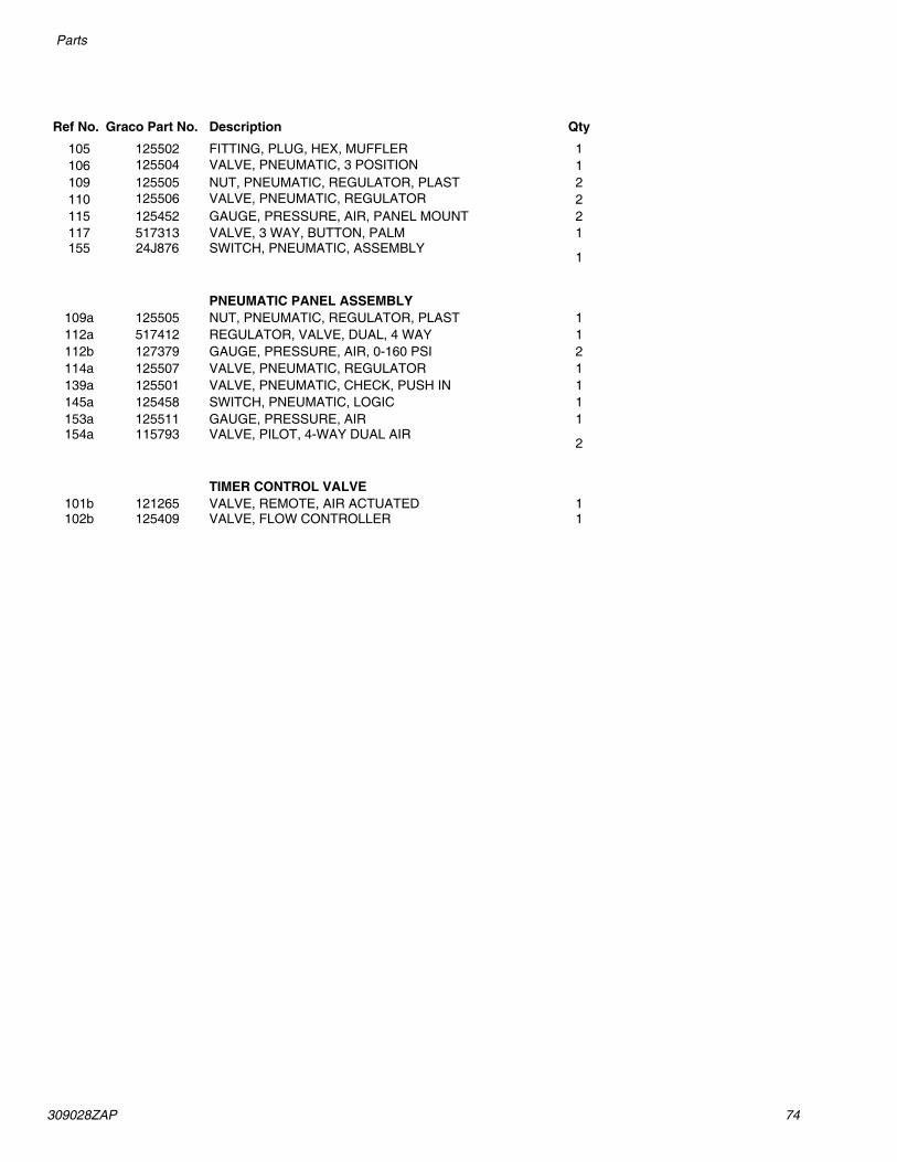
309028ZAP 74
Parts
Ref No. Graco Part No. Description Qty
105 125502 FITTING, PLUG, HEX, MUFFLER 1106 125504 VALVE, PNEUMATIC, 3 POSITION 1109 125505 NUT, PNEUMATIC, REGULATOR, PLAST 2110 125506 VALVE, PNEUMATIC, REGULATOR 2115 125452 GAUGE, PRESSURE, AIR, PANEL MOUNT 2117 517313 VALVE, 3 WAY, BUTTON, PALM 1155 24J876 SWITCH, PNEUMATIC, ASSEMBLY
1
PNEUMATIC PANEL ASSEMBLY109a 125505 NUT, PNEUMATIC, REGULATOR, PLAST 1112a 517412 REGULATOR, VALVE, DUAL, 4 WAY 1112b 127379 GAUGE, PRESSURE, AIR, 0-160 PSI 2114a 125507 VALVE, PNEUMATIC, REGULATOR 1139a 125501 VALVE, PNEUMATIC, CHECK, PUSH IN 1145a 125458 SWITCH, PNEUMATIC, LOGIC 1153a 125511 GAUGE, PRESSURE, AIR 1154a 115793 VALVE, PILOT, 4-WAY DUAL AIR
2
TIMER CONTROL VALVE101b 121265 VALVE, REMOTE, AIR ACTUATED 1102b 125409 VALVE, FLOW CONTROLLER 1

75 309028ZAP
Parts
TIMER CONTROL VALVE (SIDE OF ENCLOSURE)

309028ZAP 76
Parts
241838 and 24V775, PLC Interface Accessory KitRef Part Ref PartNo. No. Description Qty No. No. Description Qty
201 195330 PLATE, mounting 1 215 C19254 PLUG, pipe; 1/4 npt 2202 C55568 SWITCH, pressure; 1/4 in. npt 1 216 127366 CABLE, 2 2
(241838 only) 217 195320 PANEL, junction box; 1119776 SWITCH, pressure; 1/4 in. npt 1 (241838 only) see page 79
(24V775 only) 119773 PANEL, junction box; 1203 115440 VALVE, assembly 1 (24V755 only) see page 76
(241838 only)218
C51238 U-BOLT; 6 in. x 3/8-16 (not shown) 2
119777 VALVE, assembly 1 219 C19185 JAM NUT (not shown) 4(24V775 only) 220 C19213 WASHER, lock; 3/8 (not shown) 4
204 597151 ELBOW, male 3 221 502526 VALVE, air 2205 96/0340/99 SCREW, S.H.C.; CS PL #6-32x 5/8 4 222 501014 ACTUATOR, air 2206 96/0432- WASHER, lock; CS PL #6 4 223 104172 FITTING, tube 4
1/99 224 115419 FITTING, adapter 2207 596936 SCREW, S.H.C.; 1/4-20 x 1.5 2 225 195356 KIT, accessory 1209 100016 WASHER, lock; CS PL 1/4 2 226 241839 KIT, low/empty limit; 1210 517449 MUFFLER 2 227 C07435 CORD, 5-pin; 12 ft long 3211 C07434 CORD, 5-pin; 6 ft long 1 228 114158 FITTING, adapter, Y 1212 C19407 FITTING, tube; 1/4T x 1/8P 2 229 100157 SCREW; 10-32 X 0.38 4213 103219 PLUG, pipe; 1/8 npt 1 230 C12509 TUBE; 1/4 in.; nylon 144 in.214 C19391 ELBOW, 90 degree, tube; 1/4P x 1/4 T1

77 309028ZAP
Parts
Part No. 195320 and 119773, Junction Box Panel

309028ZAP 78
Parts
Ref No. Symbol Description Remark U.L. File No. Qty
290 P-N 90 DEG. CORD GRIP DB-1090 4280 A-B PB 800T-XD2 1270 PB A-B PB 800T FX9A1 1260 SS A-B SS 800T-H2A 1250 BARRIER ENTRELEC 29104221 1240230 FU BUSS FUSS GDC-250 MA 5 X 20 mm 2220 GND ENTRELEC 0290.019.05 E160646 4210 DISC ENTRELEC 0290.041.03 K5100, 102 E40735 2200 FU ENTRELEC FUSE BLOCK 0115.662.22 FU136, 143 E40735 2190 SUP A-B SUPPRESSOR 1492-WD4SS SUP136, 144 E40735 2180 PB A-B PB #800T-A2D1 (BLACK) PB119, 122 2170 PB A-B PB #800T-A2D1 (GREEN) PB124 1
160LT A-B LIGHT WHITE #800T-PT16W
(195320 only)LT 148 E14840-NKCR
1
LT A-B LIGHT WHITE #800T-QT24W (119773 only)
LT 148 E14840-NKCR1
150 LT A-B LIGHT BLUE #800T-PT16B (195320 only)
LT110 E14840-NKCR1
LT A-B LIGHT BLUE #800T-8T24B (119773 only)
LT110 E14840-NKCR1
140 LT A-B LIGHT AMBER #800T-PT16A (195320 only)
LT 141 E14840-NKCR1
LT A-B LIGHT AMBER #800T-QT24A (119773 only)
LT 141 E14840-NKCR1
130 LT A-B LIGHT GREEN #800T-PT16G (195320 only)
LT 134, 106 E14840-NKCR2
LT A-B LIGHT GREEN #800T-QT24G (119773 only)
LT 134, 106 E14840-NKCR2
120 A-B JUMPER 0291.103.24 AR110 TERMINAL ENTRELEC 0290.011.25 E40735 31100 ENTRELEC END BARRIER 0291.041.20 190 ENTRELEC END ANCHOR 10300226 280 A-B MOUNTING CHANNEL 1492-N44 12 in70 T & B SEAL RING 5262 860 T & B LOCKNUT 141 850 P-N 90 DEG. CORD GRIP DB-890 440 TAYLOR DUCT COVER 29 in30 TAYLOR WIRE DUCT (1.5 X 2) 29 in20 HOFF PANEL #C-P2016 110 HOFF ENCLOSURE #C-SD20168 1
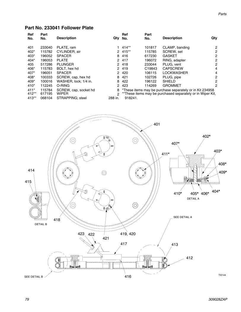
79 309028ZAP
Parts
Part No. 233041 Follower PlateRefNo.
PartNo. Description Qty
RefNo.
PartNo. Description Qty
401 233040 PLATE, ram 1 414** 101817 CLAMP, banding 2402* 115782 CYLINDER, air 2 415** 115785 SCREW, set 2403* 196052 SPACER 8 416 617230 GASKET 2404* 196053 PLATE 2 417 196072 RING, adapter 2405 517286 PLUNGER 2 418 233044 PLUG, vent 2406* 115783 BOLT, hex hd 2 419 C19843 CAPSCREW 4407* 196051 SPACER 2 420 106115 LOCKWASHER 4408* 100333 SCREW, cap, hex hd 8 421 102726 PLUG, pipe 2409* 100016 WASHER, lock; 1/4 in. 8 422 196122 SHIELD 2410* 112245 O-RING 2 423 114269 GROMMET 2411* 115784 SCREW, cap, socket hd 8 *These items may be purchase separately or in Kit 234958412** 617195 WIPER 2 **These items may be purchased separately or in Wiper Kit,413** 068104 STRAPPING; steel 288 in. 918241.
DETAIL A
DETAIL B
SEE DETAIL B
SEE DETAIL A

309028ZAP 80
Parts
Part No. 241902 Elevator Assembly
(Ref)
(Ref)
(Ref)
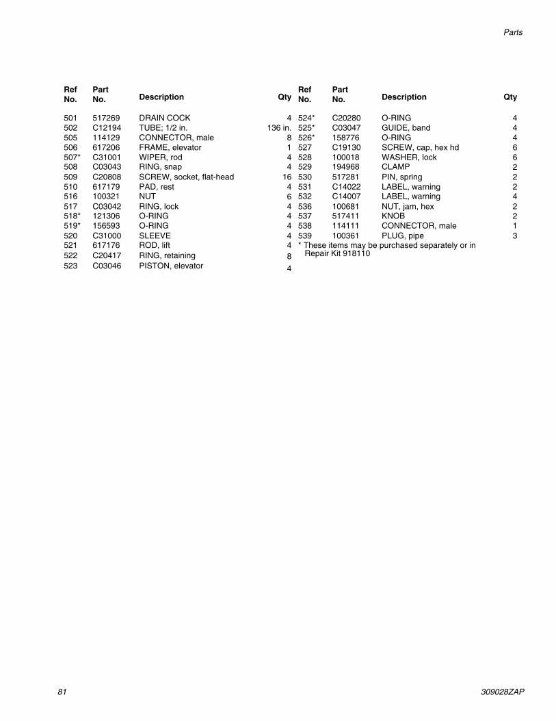
81 309028ZAP
Parts
RefNo.
Part No. Description Qty
RefNo.
PartNo. Description Qty
501 517269 DRAIN COCK 4 524* C20280 O-RING 4502 C12194 TUBE; 1/2 in. 136 in. 525* C03047 GUIDE, band 4505 114129 CONNECTOR, male 8 526* 158776 O-RING 4506 617206 FRAME, elevator 1 527 C19130 SCREW, cap, hex hd 6507* C31001 WIPER, rod 4 528 100018 WASHER, lock 6508 C03043 RING, snap 4 529 194968 CLAMP 2509 C20808 SCREW, socket, flat-head 16 530 517281 PIN, spring 2510 617179 PAD, rest 4 531 C14022 LABEL, warning 2516 100321 NUT 6 532 C14007 LABEL, warning 4517 C03042 RING, lock 4 536 100681 NUT, jam, hex 2518* 121306 O-RING 4 537 517411 KNOB 2519* 156593 O-RING 4 538 114111 CONNECTOR, male 1520 C31000 SLEEVE 4 539 100361 PLUG, pipe 3521 617176 ROD, lift 4 * These items may be purchased separately or in522 C20417 RING, retaining 8 Repair Kit 918110523 C03046 PISTON, elevator 4

309028ZAP 82
Recommended Spare Parts
Recommended Spare PartsSpare Parts for Pump and Air Motor
See appropriate manual listed on page 3.
Spare Parts for 47:1 and 35:1 Uni-Drum Supply UnitsThe customer should maintain an inventory of the spare parts (per unit) listed below.
CSTUnits
SSTUnits
Description Qty. CSTUnits
SSTUnits
Description Qty.
515147 515147 AIR REGULATOR 1 C20247 C20247 O-RING 2V1M350 V1M350 RECIRCULATING VALVE 2 517286 517286 PLUNGER 2
KIT, see manual 3A1792 C03039 C03039 UNI-DRUM ELEVATOR KIT 2115440 115440 VALVE, solenoid 1 162440 162440 BOWL SEAL 1C55568 C55568 SWITCH, pressure 1 502526 502526 PILOT VALVE 1C07560 C07560 SWITCH, limit 1 501014 501014 ACTUATOR 1102774 102774 LUBRICATOR KIT 1 918110 918110 AIR CYLINDER KIT 1517285 517285 AIR CYLINDER 1 918241 918241 WIPER KIT 1
234958 234958 FOLLOWER PLATE VENT 1VALVE KIT

83 309028ZAP
Recommended Spare Parts
TI02
07
POW
ERED
FRO
M P
LC C
ON
TRO
L PA
NEL
AIR
PRE
SSU
RE O
N
INPU
T TO
PLC
IND
ICAT
ES A
IR
AVA
ILA
BLE
TO U
NLO
AD
ER
NEU
TRA
L W
HIT
E
GRE
EN
LOCA
TED
OU
TSID
E TH
IS P
AN
EL.
WIR
E A
SSIG
NED
AT
REM
OTE
DEV
ICE
FILE
WIR
ING
LEG
END
NEU
TRA
L YE
LLO
W
POW
ER
POW
ER
RAK
CON
TRO
L
RED YE
LLO
W
PLC
POW
ER
CON
NEC
TIO
N
RAM
REA
DY
INPU
T TO
PLC
IND
ICAT
ES
DRU
M IN
PLA
CE
LOW
LEV
EL
INPU
T TO
PLC
IND
ICAT
ES
DRU
M L
OW
LEV
EL
DRU
M E
MPT
Y IN
PUT
TO P
LC IN
DIC
ATES
D
RUM
EM
PTY
DEP
RESS
URI
ZE P
UM
P O
UTP
UT
FRO
M P
LC
NO
TE: I
F O
UTP
UT
IS H
IGH
(O
PEN
), PU
MPS
WIL
L D
EPRE
SSU
RIZE
PUM
P AC
TIVE
(LIG
HT)
OU
TPU
T FR
OM
PLC
PUM
P AC
TIVE
OU
TPU
T FR
OM
PLC
TU
RNS
AIR
ON
TO
PU
MPS
PUM
P RE
AD
Y O
UTP
UT
FRO
M P
LC
IND
ICAT
ES R
EAD
Y FO
R C
HA
NG
EOVE
R
BULK
SU
PPLY
D
EPRE
SSU
RIZA
TIO
N
(NO
T AC
TIVA
TED
)
LOCA
L R
EMO
TE
REM
OTE
MO
DE
SYST
EM P
RESS
URI
ZED
OU
TPU
T FR
OM
PLC
PRIM
E PU
MP
INPU
T TO
PLC
RESE
T PJ
MP
INPU
T TO
PLC
PUM
P O
N
INPU
T TO
PLC
CYCL
E CO
UN
T P
UM
P 1
PRO
X. S
WIT
CH
INPU
T TO
PLC
CYCL
E CO
UN
T PU
MP
2 PR
OX.
SW
ITCH
IN
PUT
TO P
LC
Ele
ctri
cal D
iagr
amJu
nctio
n B
ox P
anel

309028ZAP 84
Recommended Spare Parts
LEG
END
DV
- DIR
ECTI
ON
AL
VALA
VEIV
- IM
PULS
E VA
LVE
SV -
SHU
TTLE
VA
LVE
R - R
EGU
LATO
RI -
IND
ICAT
OR
GA
- G
AUG
E
RAM
PLA
TE
VEN
T 2
RAM
PLA
TE
VEN
T 1
LOCA
TED
ON
UN
IDRU
M
RAM
PLA
TE
PUM
P #1
PUM
P #2
MA
IN A
IR
FILT
ER
MA
IN A
IR ’I
N’
UN
IDRU
M A
SSEM
BLY
LOCK
-OU
T VA
LVE
DV9
BOX
VEN
T
BOX
VEN
T
AUTO
OPE
N
FOLL
OW
ERVE
NTRE
GU
LATO
R
VEN
T O
PEN
VEN
T CL
OSE
TRA
M D
OW
N
PUM
P 1
REM
OTE
REG
ULA
RTO
R SI
GN
AL
DEP
RESS
URI
ATIO
N
VALV
EPR
ESU
RE
SWIT
CH
PS10
8
SOL
SOL
PILO
TED
RE
GU
LATO
R PU
MP2
LOCA
TED
ON
J-
BOX
PAN
ELPI
LOTE
D
REG
ULA
TOR
PUM
P1
PUM
P 2
REM
OTE
REG
ULA
RTO
R SI
GN
AL
RAM
UP
SAFE
TY
DV8
B PI
LOT
A P
ILO
T
RAM
UP
UN
IDRU
M R
AM
DV2
(B
OTT
OM
)
DV3
(T
OP)
RAM
CO
NTR
OL
DV6
RAIS
E
LOW
ER
CYLI
ND
ER E
XHAU
ST
MA
IN A
IR S
UPP
LY F
OR
SOLE
NO
ID V
ALV
ES &
SO
LEN
OID
PR.
SW
ITCH
PUM
P #2
REG
ULA
TOR
PUM
P #1
REG
ULA
TOR
PUM
P #2
Pne
umat
ic D
iagr
amP
neum
atic
Lay
out P
anel

85 309028ZAP
Technical Data
Technical Data
Unit Description SpecificationUni-Drum System 248306, 248307, 249339, 249340, 253676, 253677
Overall dimensions: Width: 69 in. (1753 mm)Depth: 51 in. (1295 mm)Height (lowered): 85.2 in. (2164 mm) Height (raised): 141 in. (3581 mm)
Supply Units (LH and RH)
Compressed air requirement 80 psi maximum (5.5 bar, 0.55 MPa) 450 cfm
Main air inlet size 1 in. npt(f)Overall Weight Approximately 3950 lb (1792 kg)
Pumps (1/unit) 24Y228, 24Y227
Ratio 47:1 fluid to air power ratio
Maximum fluid working pressure 4500 psi (310 bar, 31.0 MPa)
Maximum air input pressure 95 psi (7 bar, 0.7 MPa)
Pump cycles 8.7 per 1 gal. (3.8 liters)Recommended pump speed for continuous operation
60 cycles per min
Maximum flow rate 6.9 gpm (26.1 liters/min) at 60 cycles/min
Air motor piston effective area 132.7 in.2 (856 cm2)
Stroke length 4.8 in. (122 mm)
Air motor cylinder inside diameter 13 in. (330mm)Displacement pump effective area 2.79 in.2 (18 cm2)
Pump operating temperature 150° F (65.5° C) maximum temperatureAir inlet size 1 in. npt(f)
Fluid inlet size 2 in. npt(f)
Fluid outlet size 1-1/2 in. npt(m)Wetted components 304, 329, and 17-4 PH Grades of stainless steel;
silicone nitride; acetal; Ultra-high molecular weight polyethylene, and leather
Weight Approx. 234 lbs. (106 kg) per pump
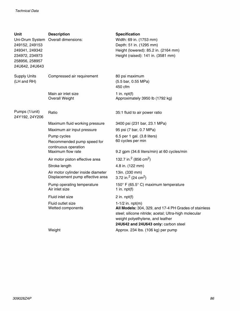
309028ZAP 86
Technical Data
Unit Description SpecificationUni-Drum System 249152, 249153 249341, 249342 234972, 234973 258956, 258957 24U642, 24U643
Overall dimensions: Width: 69 in. (1753 mm)Depth: 51 in. (1295 mm)Height (lowered): 85.2 in. (2164 mm) Height (raised): 141 in. (3581 mm)
Supply Units (LH and RH)
Compressed air requirement 80 psi maximum (5.5 bar, 0.55 MPa) 450 cfm
Main air inlet size 1 in. npt(f)Overall Weight Approximately 3950 lb (1792 kg)
Pumps (1/unit) 24Y192, 24Y206
Ratio 35:1 fluid to air power ratio
Maximum fluid working pressure 3400 psi (231 bar, 23.1 MPa)
Maximum air input pressure 95 psi (7 bar, 0.7 MPa)
Pump cycles 6.5 per 1 gal. (3.8 liters)Recommended pump speed for continuous operation
60 cycles per min
Maximum flow rate 9.2 gpm (34.6 liters/min) at 60 cycles/min
Air motor piston effective area 132.7 in.2 (856 cm2)
Stroke length 4.8 in. (122 mm)
Air motor cylinder inside diameter 13in. (330 mm)Displacement pump effective area 3.72 in.2 (24 cm2)
Pump operating temperature 150° F (65.5° C) maximum temperatureAir inlet size 1 in. npt(f)
Fluid inlet size 2 in. npt(f)
Fluid outlet size 1-1/2 in. npt(m)Wetted components All Models: 304, 329, and 17-4 PH Grades of stainless
steel; silicone nitride; acetal; Ultra-high molecular weight polyethylene, and leather 24U642 and 24U643 only: carbon steel
Weight Approx. 234 lbs. (106 kg) per pump
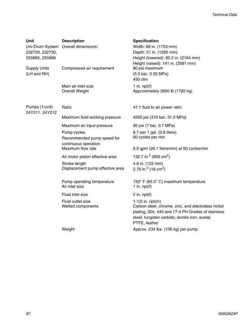
87 309028ZAP
Technical Data
Unit Description SpecificationUni-Drum System 232729, 232730, 255665, 255666
Overall dimensions: Width: 69 in. (1753 mm)Depth: 51 in. (1295 mm)Height (lowered): 85.2 in. (2164 mm) Height (raised): 141 in. (3581 mm)
Supply Units (LH and RH)
Compressed air requirement 80 psi maximum (5.5 bar, 0.55 MPa)450 cfm
Main air inlet size 1 in. npt(f)Overall Weight Approximately 3950 lb (1792 kg)
Pumps (1/unit) 24Y211, 24Y212
Ratio 47:1 fluid to air power ratio
Maximum fluid working pressure 4500 psi (310 bar, 31.0 MPa)
Maximum air input pressure 95 psi (7 bar, 0.7 MPa)
Pump cycles 8.7 per 1 gal. (3.8 liters)Recommended pump speed for continuous operation
60 cycles per min
Maximum flow rate 6.9 gpm (26.1 liters/min) at 60 cycles/min
Air motor piston effective area 132.7 in.2 (856 cm2)
Stroke length 4.8 in. (122 mm)Displacement pump effective area 2.79 in.2 (18 cm2)
Pump operating temperature 150° F (65.5° C) maximum temperatureAir inlet size 1 in. npt(f)
Fluid inlet size 2 in. npt(f)
Fluid outlet size 1-1/2 in. npt(m)Wetted components Carbon steel, chrome, zinc, and electroless nickel
plating; 304, 440 and 17-4 PH Grades of stainless steel; tungsten carbide; ductile iron; acetal; PTFE, leather
Weight Approx. 234 lbs. (106 kg) per pump
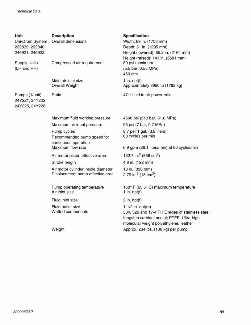
309028ZAP 88
Technical Data
Unit Description SpecificationUni-Drum System 232839, 232840, 246921, 246922
Overall dimensions: Width: 69 in. (1753 mm)Depth: 51 in. (1295 mm)Height (lowered): 85.2 in. (2164 mm) Height (raised): 141 in. (3581 mm)
Supply Units (LH and RH)
Compressed air requirement 80 psi maximum (5.5 bar, 0.55 MPa) 450 cfm
Main air inlet size 1 in. npt(f)Overall Weight Approximately 3950 lb (1792 kg)
Pumps (1/unit) 24Y221, 24Y222, 24Y225, 24Y226
Ratio 47:1 fluid to air power ratio
Maximum fluid working pressure 4500 psi (310 bar, 31.0 MPa)
Maximum air input pressure 95 psi (7 bar, 0.7 MPa)
Pump cycles 8.7 per 1 gal. (3.8 liters)Recommended pump speed for continuous operation
60 cycles per min
Maximum flow rate 6.9 gpm (26.1 liters/min) at 60 cycles/min
Air motor piston effective area 132.7 in.2 (856 cm2)
Stroke length 4.8 in. (122 mm)
Air motor cylinder inside diameter 13 in. (330 mm)Displacement pump effective area 2.79 in.2 (18 cm2)
Pump operating temperature 150° F (65.5° C) maximum temperatureAir inlet size 1 in. npt(f)
Fluid inlet size 2 in. npt(f)
Fluid outlet size 1-1/2 in. npt(m)Wetted components 304, 329 and 17-4 PH Grades of stainless steel;
tungsten carbide; acetal; PTFE, Ultra-high molecular weight polyethylene, leather
Weight Approx. 234 lbs. (106 kg) per pump

89 309028ZAP
Technical Data

All written and visual data contained in this document reflects the latest product information available at the time of publication. Graco reserves the right to make changes at any time without notice.
Original instructions. This manual contains English. MM 309028Graco Headquarters: Minneapolis
International Offices: Belgium, China, Japan, Korea
GRACO INC. AND SUBSIDIARIES • P.O. BOX 1441 • MINNEAPOLIS MN 55440-1441 • USACopyright 2000, Graco Inc. All Graco manufacturing locations are registered to ISO 9001.
www.graco.comRevision ZAP, January 2018
Graco Standard WarrantyGraco warrants all equipment referenced in this document which is manufactured by Graco and bearing its name to be free from defects in material and workmanship on the date of sale to the original purchaser for use. With the exception of any special, extended, or limited warranty published by Graco, Graco will, for a period of twelve months from the date of sale, repair or replace any part of the equipment determined by Graco to be defective. This warranty applies only when the equipment is installed, operated and maintained in accordance with Graco’s written recommendations.
This warranty does not cover, and Graco shall not be liable for general wear and tear, or any malfunction, damage or wear caused by faulty installation, misapplication, abrasion, corrosion, inadequate or improper maintenance, negligence, accident, tampering, or substitution of non-Graco component parts. Nor shall Graco be liable for malfunction, damage or wear caused by the incompatibility of Graco equipment with structures, accessories, equipment or materials not supplied by Graco, or the improper design, manufacture, installation, operation or maintenance of structures, accessories, equipment or materials not supplied by Graco.
This warranty is conditioned upon the prepaid return of the equipment claimed to be defective to an authorized Graco distributor for verification of the claimed defect. If the claimed defect is verified, Graco will repair or replace free of charge any defective parts. The equipment will be returned to the original purchaser transportation prepaid. If inspection of the equipment does not disclose any defect in material or workmanship, repairs will be made at a reasonable charge, which charges may include the costs of parts, labor, and transportation.
THIS WARRANTY IS EXCLUSIVE, AND IS IN LIEU OF ANY OTHER WARRANTIES, EXPRESS OR IMPLIED, INCLUDING BUT NOT LIMITED TO WARRANTY OF MERCHANTABILITY OR WARRANTY OF FITNESS FOR A PARTICULAR PURPOSE.
Graco’s sole obligation and buyer’s sole remedy for any breach of warranty shall be as set forth above. The buyer agrees that no other remedy (including, but not limited to, incidental or consequential damages for lost profits, lost sales, injury to person or property, or any other incidental or consequential loss) shall be available. Any action for breach of warranty must be brought within two (2) years of the date of sale.
GRACO MAKES NO WARRANTY, AND DISCLAIMS ALL IMPLIED WARRANTIES OF MERCHANTABILITY AND FITNESS FOR A PARTICULAR PURPOSE, IN CONNECTION WITH ACCESSORIES, EQUIPMENT, MATERIALS OR COMPONENTS SOLD BUT NOT MANUFACTURED BY GRACO. These items sold, but not manufactured by Graco (such as electric motors, switches, hose, etc.), are subject to the warranty, if any, of their manufacturer. Graco will provide purchaser with reasonable assistance in making any claim for breach of these warranties.
In no event will Graco be liable for indirect, incidental, special or consequential damages resulting from Graco supplying equipment hereunder, or the furnishing, performance, or use of any products or other goods sold hereto, whether due to a breach of contract, breach of warranty, the negligence of Graco, or otherwise.
FOR GRACO CANADA CUSTOMERSThe Parties acknowledge that they have required that the present document, as well as all documents, notices and legal proceedings entered into, given or instituted pursuant hereto or relating directly or indirectly hereto, be drawn up in English. Les parties reconnaissent avoir convenu que la rédaction du présente document sera en Anglais, ainsi que tous documents, avis et procédures judiciaires exécutés, donnés ou intentés, à la suite de ou en rapport, directement ou indirectement, avec les procédures concernées.
Graco InformationSealant and Adhesive Dispensing EquipmentFor the latest information about Graco products, visit www.graco.com.For patent information, see www.graco.com/patents. TO PLACE AN ORDER, contact your Graco distributor, go to www.graco.com and select “Where to Buy” in the top blue bar, or call to find the nearest distributor.
If calling from the US: 800-746-1334If calling from outside the US: 0-1-330-966-3000


![[Drum] Bob Moses - Drum Wisdom](https://img.dokumen.tips/doc/110x75/577cbfd31a28aba7118e36ec/drum-bob-moses-drum-wisdom.jpg)