Embed Size (px)
Citation preview

Computers and Geotechnics 62 (2014) 128–135
Contents lists available at ScienceDirect
Computers and Geotechnics
journal homepage: www.elsevier .com/ locate/compgeo
Technical Communication
Undrained stability of surface strip footings above voids
http://dx.doi.org/10.1016/j.compgeo.2014.07.0090266-352X/� 2014 Elsevier Ltd. All rights reserved.
⇑ Corresponding author. Tel.: +82 2 2123 2807; fax: +82 2 364 5300.E-mail address: [email protected] (S. Jeong).
Joon Kyu Lee, Sangseom Jeong ⇑, Junyoung KoDept. of Civil and Environmental Engineering, Yonsei University, 50 Yonsei-ro, Seodaemun-gu, Seoul 120-749, Republic of Korea
a r t i c l e i n f o a b s t r a c t
Article history:Received 27 May 2014Received in revised form 23 June 2014Accepted 8 July 2014
Keywords:Strip footingVoidFinite element analysisUndrained bearing capacityClay
This paper investigates the undrained vertical bearing capacity of surface strip footings on clay with sin-gle and dual continuous voids. Numerical solutions for a wide range of geometric and material combina-tions are obtained by small strain finite element analysis. Based on the results, design charts are providedfor the calculation of the undrained bearing capacity factors as a function of the dimensionless parame-ters related to the vertical and horizontal void distances from the footing, void width and height, andspacing between the two voids as well as soil rigidity and non-homogeneity. In the footing-above-voidsystem, the ultimate bearing capacity of the footing is governed by the three failure mode: roof, wall,and combined failure mechanisms.
� 2014 Elsevier Ltd. All rights reserved.
1. Introduction
In engineering practice, the existence of underground voidsunder rigid surface structures (e.g., pavements, pipelines andfootings) requires special attention because voids can influencethe integrity of structures. Voids in ground are known to formfor many reasons, some of which are the thawing of subsurfaceice lenses [1], the dynamic loadings induced by mining and tun-neling activities [2], the dissolution of soluble materials such assalt, gypsum, limestone and dolomite [3], the dissociation ofmethane hydrate [4], and the presence of leaking CO2 storagereservoirs [5]. The size, shape and evolution of voids depend onthe lithology of soils and rocks, and the initial depth of voids[6]. In particular, large voids are often found in karsticenvironment [7].
The performance of footings underlain by subsurface voids hasbeen investigated by several researchers. Baus and Wang [8] stud-ied experimentally and numerically the bearing capacity behaviorof strip footings on silty clay with single continuous voids, andshowed that for a given void size, the bearing capacity decreasesas the distance between the footing and void reduces. Wang andhis colleagues continuously explored the effects of void location,size, shape, and orientation with respect to the footing axis onthe stability of square footings with different sizes, shapes andembedment depths [9,10]. Wood and Larnach [11] conductedanother study on this subject by using physical modeling andnumerical simulation, and reported similar behaviors observed in
Wang’s works. Wang and Hsieh [12] developed the three failuremechanisms that are considered to model the collapse of stripfooting centered above a single circular void by using the upperbound theorem of limit analysis. Al-Tabbaa et al. [13] observedthe load-settlement characteristics of model strip footings overcontinuous circular voids in cemented mixed sand. The resultsindicated that the greater depth and offset of voids cause thehigher strength and stiffness of the system. Sreng et al. [14] pre-sented the result of rotation response of strip footings above con-tinuous square voids, which is obtained by measuring bothvertical and horizontal displacements during 1 g model tests. Morerecently, Kiyosumi et al. [15] performed plain strain finite element(FE) analyses to examine the influence of multiple voids on theyield pressure of strip footing resting on calcareous soil, and statedthat the failure zone developed significantly towards the nearestvoid from the footing and does not typically extend to the othervoids. Kiyosumi et al. [16] reported the results of laboratory scalemodel tests of strip footing on stiff ground with continuous squarevoids and revealed the three types of collapse modes for a singlevoid: bearing failure without void collapse, bearing failure withvoid collapse, and void failure without bearing failure. Even thoughseveral studies have been reported on the footing-above-void sys-tem, most works have focused on cohesive-frictional soils. In con-trast, the undrained stability of footings overlying voids has notbeen discussed in the literature.
The bearing capacity of surface strip footings (both drained andundrained) is usually estimated using the bearing capacity formulasuggested by Meyerhof [17]. The solution for the simplest case ofundrained condition is identical to the exact solution of Prandtl[18], which is expressed as

su0 su
su = su0+kz
z
1
k
B
Rigid strip footing
UndrainedclayEu, B
B
nB
mB
C.L.
(a) Plane strain footing above single void
B
sB
C.L.
sB
C.L.
(b) Parallel configuration (c) Symmetrical configuration
Fig. 1. Problem definition (modified from Kiyosumi et al. [15]).
0.00 0.01 0.02 0.03 0.04 0.05 0.06 0.07 0.08w/B
0
100
200
300
400
Q/B(kPa)
= 1.5
= 2.0
= 2.5
= 3.0= 3.5
= 4.0
Single square void=0, m=1, n=1,Eu/su=500, kB/suo=0
Fig. 3. Load–displacement curves for strip footing centered above single voids.
J.K. Lee et al. / Computers and Geotechnics 62 (2014) 128–135 129
qu ¼Q u
B¼ suNc ð1Þ
where qu is the ultimate bearing stress on the footing, Qu is the ulti-mate vertical force, B is the footing width, su is the undrained shearstrength of the soil, and Nc is the dimensionless undrained bearingcapacity factor.
This paper presents FE analyses for the calculation of the bear-ing capacity of surface strip footings on undrained clay with singleand dual continuous voids. Consideration is given to the effects ofvoid location, shape and number as well as soil rigidity and non-homogeneity. The results of the analyses are compared to other
9.5B9.5B B
20B
Detail
Fig. 2. Typical finite element mesh and boundar
available solutions. Based on the analyses, design charts are pre-sented in form of the undrained bearing capacity factor withrespect to the dimensionless influencing parameters, and the gov-erning failure mechanisms are discussed.
2. Problem definition
Fig. 1 illustrates the problem geometry studied and defines thekey parameters. As shown in Fig. 1(a), a strip rigid footing of widthB is placed on an isotropic, non-homogenous soil with a undrainedYoung’s modulus Eu, a uniform unit weight c, a surface undrainedshear strength su0, and a rate of strength increasing with depth k.The undrained strength of the soil at a depth z is given as
suðzÞ ¼ suo þ kz ð2Þ
The undrained shear strength profile is common in normallyconsolidated (NC) clay, and k ¼ 0 corresponds to the homogeneousclay with uniform strength. Such strength variation is quantified interms of the nondimensional parameter kB=suo, which ranges typ-ically between 0 and 1 for onshore applications [19,20].
The performance of a footing above voids is affected by the loca-tion, shape and number of voids [15], which are expressed throughdimensionless parameters, i.e., the vertical void distance a (definedas the ratio of vertical distance from the ground surface to the
15B
Detail of mesh around footing
Mesh refine zone
y extension for soil and foundation domain.
130 J.K. Lee et al. / Computers and Geotechnics 62 (2014) 128–135
center of the void), horizontal void distance b (defined as the ratioof the horizontal distance from the centerline of the footing to thecenter of the void), void width n (defined as the ratio of the voidwidth to the footing width), and void height m (defined as the ratioof the void height to the footing width). The dual voids separatedby the void spacing s (defined as the ratio of the center-to-centerspacing of two voids to the footing width) are considered in thisstudy, and their configuration is designed to two groups, i.e., paral-lel and symmetrical configurations, as shown in Fig. 1 (b) and (c),respectively.
3. Finite element analysis
Small strain finite element analyses of surface strip footingsabove voids were carried out using a commercially available Plaxis2D Version 2012 [21]. The soil was modeled with fifteen-node tri-angular elements while the footing was composed of six-node tri-angular plate elements that are compatible with triangular side ofthe degenerated soil elements.
The soil surrounding the voids was modeled as a Tresca mate-rial using the elastic-perfectly plastic Mohr–Coulomb failure crite-ria. Poisson’s ratio of m ¼ 0:495 and friction and dilation angles of/ ¼ w ¼ 0 were set to simulate the undrained clay. The undrainedYoung’s modulus and bulk unit weight were assumed to beEu ¼ 30 MPa and c ¼ 20 kN=m3, respectively. It is worth notingthat the undrained bearing capacity of a surface footing restingon level ground is insensitive to the soil unit weight [22]. The threedifferent values of undrained shear strength of the soil were taken
1.0 1.5 2.0 2.5 3.0 3.5 4.0 4.5 5.0
0
1
2
3
4
5
6
7(a) Single square void=0, m=1, n=1, kB/suo=0
Eu/su = 100Eu/su = 300Eu/su = 500
0.0 0.5 1.0 1.5 2.0 2.5 3.0 3.5 4.0 4.5
0
1
2
3
4
5
6
7(b) Single square void=1.5, m=1, n=1, kB/suo=0
Eu/su = 100Eu/su = 300Eu/su = 500
cN
cN
Fig. 4. Effect of soil rigidity on bearing capacity factor of strip footings above singlevoids.
as su = 60, 100 and 300 kPa, and the soil rigidity Eu=su was constant,irrespective of depth. The footing was modeled as a non-porouslinear elastic material with 1 m thickness and Young’s modulusfor concrete Ec ¼ 30 GPa. The geostatic stress was generated bytaking the coefficient of earth pressure at rest, K0 ¼ 1.
Fig. 2 shows a typical finite element (FE) mesh and boundaryextensions of the soil domain for the plain strain surface footing.The external boundaries were positioned 9:5B laterally from theedge of the foundation and 15B below the ground surface, whichminimizes possible boundary effect on the predicted bearingcapacity. Zero horizontal displacements were prescribed at the lat-eral boundaries and full fixities at the bottom boundary. The voidswere introduced by excavation of the soil at the designed depth foreach analysis. Since the mesh density in the area adjacent to thefootings, particularly at level ground, is of most importance forthe bearing capacity factor calculation, element density wasincreased in this area. The optimum size and distribution of ele-ments were taken to be obtained when further modification of ele-ments did not provide a further reduction in the value of bearingcapacity factor calculated. The total number of elements variedfrom 3003 to 5235, depending on geometrical parameters.
No special interface elements along the soil and footing inter-face were used, indicating that the footing was simulated as roughwith the same shear strength and shear modulus for the interfaceand adjacent soil elements. Instead, to allow an effective gap toform between part of the footing and the soil, a very thin 0.03 mzone of zero tensile strength soil elements was modeled beneath
0.0 0.5 1.0 1.5 2.0 2.5 3.0 3.5 4.0 4.50
1
2
3
4
5
6
7
c =1.5
=2.0
=2.5
=3.0=3.5
=4.0(a) Single square voidm=1, n=1, Eu/su=500, kB/suo=0
1.0 1.5 2.0 2.5 3.0 3.5 4.0 4.5
0.0
0.5
1.0
1.5
2.0
2.5
3.0
= - 0.16 2 + 0.08 + 2.77
(b) Single square voidm=1, n=1, Eu/su=500, kB/suo=0
Nc, max0.9Nc, max0.8Nc, max
Fig. 5. Bearing capacity factor of strip footings above single voids and their criticalvoid locations.

J.K. Lee et al. / Computers and Geotechnics 62 (2014) 128–135 131
the footing, indicating that the interface elements cannot sustaintension [23].
Fig. 3 shows the typical normalized load–displacement curvesfor the footings centered above voids (i.e., b ¼ 0), where w repre-sents the displacement of the footings corresponding to the mobi-lized vertical force Q . For all cases, the footing reaches a clear limitload, which was taken as the ultimate bearing capacity.
4. Results and discussion
Fig. 4 shows the effect of soil rigidity on the bearing capacityfactor of strip footings above single square voids. The soil rigidityhas little influence on the capacity factor, irrespective of the voidlocation. It is noted that the bearing capacity of a surface footingresting on ground is independent of the soil rigidity [24]. The soilrigidity is taken as Eu=su ¼ 500 for further numerical calculations.The results also indicate that the influence of void location onthe footing bearing capacity decreases as the distance betweenthe void and footing increases, and there exists a certain locationbeyond which the void effect on the undrained stability of the foot-ing become negligible, as described by Baus and Wang [8]. Fig. 4(a)shows that for a given value of b ¼ 0, the capacity factor increaseslinearly with the value of a up to a limiting value, defined as themaximum bearing capacity factor Nc;max. The value of Nc;max
obtained from the current FE analyses is 5.16, which is 0.4% higherthan the Prandtl solution of 2þ p. A similar variation of capacityfactor with respect to b for a constant value of a ¼ 1:5 is shownin Fig. 4(b). The values of the capacity factors for b ¼ 0 anda ¼ 1:5 can be approximated by the following equations:
Fig. 6. Bearing capacity factor of strip footings above single rectangular voids.
Nc ¼ 1:47a 6 Nc;max ð3Þ
Nc ¼ 1:26bþ 2:00 6 Nc;max ð4Þ
Fig. 5(a) shows the variation of the bearing capacity factor ofstrip footing with b for different values of a. The capacity factorincreases with an increase in the value of a, but the capacity factorwith lower a significantly increases with the value of b. It is alsofound that the value of bcr , representing the critical void eccentric-ity at which the capacity factor becomes equal to the maximumbearing capacity factor, decreases with increasing the value of a.From Fig. 5(a), the critical void location is determined, which isdenoted by the solid line in Fig. 5(b). When the void is locatedabove the line, the existence of the void can be ignored, implyingthat the capacity factors are same as Nc;max. When the void islocated below the line, however, the capacity factor varies withthe void location, obviously less than the value of Nc;max. The equiv-alent lines of the capacity factors with 0:9Nc;max and 0:8Nc;max arerepresented by the dotted lines in Fig. 5(b).
Fig. 6 shows the bearing capacity factor of strip footings cen-tered above the single rectangular voids that are wider than theyare high. Fig. 6(a) shows the results for void cases with varyingthe void width parameter n but the constant void height parameterof m ¼ 1. At a given value of a, the capacity factor normallydecreases as the value of n increases. The rate of reduction incapacity factor is insensitive to the overall value of a, particularlyfor the value of n > 1:5. Fig. 6(b) shows the results for void caseswith different combinations of n and m but the constant area ofthe cross-section, i.e., mn ¼ 1. At a given value of a, the capacity
Fig. 7. Bearing capacity factor of strip footings on inhomogeneous clay with singlevoids.
132 J.K. Lee et al. / Computers and Geotechnics 62 (2014) 128–135
factor is found to increase gradually with an increase in the valueof m.
Fig. 7 shows the variation of bearing capacity factor as a func-tion of soil non-homogeneity for given values of a and b. Asexpected, the greater value of kB=suo gives the higher capacity fac-tor. Furthermore, the maximum bearing capacity factor increasescontinuously with an increase in the value of kB=suo. ForkB=suo ¼ 0:5 and 1, the maximum bearing capacity factors ofSkempton [25] are estimated to be 5.83 and 6.67, respectively.Another solution obtained using the method of characteristics[26] is 5.79 and 6.47, respectively. The corresponding values ofNc;max by the current FE analysis are lower than the existing solu-tions. Meanwhile, the critical void location generally decreaseswith increasing the value of kB=suo.
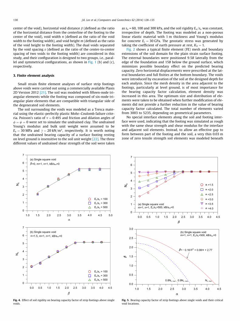
Fig. 8 shows the bearing capacity factor of strip footings abovedual square voids. The results reveal that regardless of the voidconfiguration (i.e., parallel and symmetrical configurations), thecapacity factor increases as the two voids are moved further apart.This is attributed to the higher shear resistance provided by awider pillar between the adjacent voids. Fig. 8(a) shows that forall vertical void distance parameter except for a ¼ 4:5, the capacityfactor increases with the value of s and reaches at a certain value,identical to the capacity factor for single void cases shown inFig. 4(a). Fig. 8(b) shows that the capacity factor increases withincreasing the value of s, although this trend is predominant atthe lower values of a. In general, as the value of s increases, the rateof increase in capacity factor first increases, then decrease andeventually approaches zero. It is noteworthy that the footing bear-ing capacity for dual square voids with s ¼ 1 becomes equal to that
Fig. 8. Bearing capacity factor of strip footings above dual voids.
of single rectangular voids with the combination of n ¼ 2 andm ¼ 1.
From Fig. 8, the critical spacing of dual voids with the paralleland symmetrical configurations is determined and plotted inFig. 9(a). The critical spacing is the spacing beyond which thecapacity factor becomes equals to unity, indicating no interferenceeffect. For the parallel configuration, the critical spacing is notaffected by the value of a. For the symmetrical configuration, how-ever, the critical spacing linearly decreases with increasing thevalue of a. Fig. 9(b) compares the bearing capacity factors for theparallel and symmetrical dual-void configurations, together withthe result for the single void cases shown in Fig. 4(a). For all valuesof a and s, the capacity factor for the single void cases is higherthan that for the dual void with parallel configuration. It is alsofound that the symmetrical configuration has higher capacity fac-tor compared to the parallel configuration, and their difference ishigher at the lower values of a and the higher values of s.
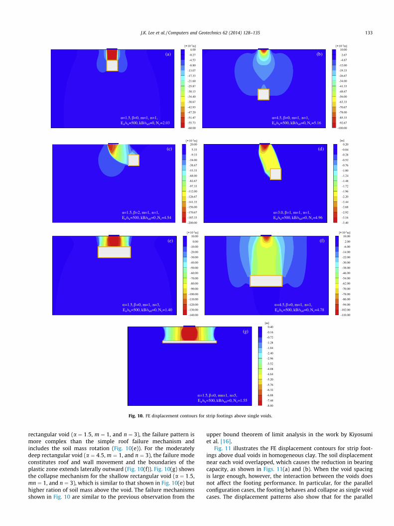
Fig. 10 illustrates the FE displacement contours at collapse forstrip footings above single voids in homogeneous clay. The failuremode is strongly dependent on the location and shape of voids. Forshallow square voids, the estimation of collapse loads are given bythe roof failure mechanism, characterized by the downward move-ment of a rigid soil block immediately above the void. Fig. 10(a)shows a typical type of the roof failure for the shallowest squarevoid (a ¼ 1:5, m ¼ 1, and n ¼ 1). As the void location is verticallyand horizontally farther from the footing, the collapse modebecomes wider and deeper, and involves the combination of theroof and wall failure mechanisms (Fig. 10(b)–(d)). For the shallow
Fig. 9. Comparisons of critical spacing ratio and undrained bearing capacity for dualvoids with parallel and symmetrical configurations.
=1.5, =0, m=1, n=1, Eu/su=500, kB/su0=0, Nc=2.03
(a)4.00
-0.27
-4.53
-8.80
-13.07
-17.33
-21.60
-25.87
-30.13
-34.40
-38.67
-42.93
-47.20
-51.47
-55.73
-60.00
[ 10-3m]
=4.5, =0, m=1, n=1, Eu/su=500, kB/su0=0, Nc=5.16
(b)10.00
2.67
-4.67
-12.00
-19.33
-26.67
-34.00
-41.33
-48.67
-56.00
-63.33
-70.67
-78.00
-85.33
-92.67
-100.00
[ 10-3m]
=1.5, =2, m=1, n=1, Eu/su=500, kB/su0=0 ,Nc=4.54
(c)20.00
5.33
-9.33
-24.00
-38.67
-53.33
-68.00
-82.67
-97.33
-112.00
-126.67
-141.33
-156.00
-170.67
-185.33
-200.00
[ 10-3m]0.20
-0.04
-0.28
-0.52
-0.76
-1.00
-1.24
-1.48
-1.72
-1.96
-2.20
-2.44
-2.68
-2.92
-3.16
-3.40
[m]
=3.0, =1, m=1, n=1, Eu/su=500, kB/su0=0, Nc=4.96
(d)
=1.5, =0, m=1, n=3, Eu/su=500, kB/su0=0, Nc=1.40
(e)10.00
0.00
-10.00
-20.00
-30.00
-40.00
-50.00
-60.00
-70.00
-80.00
-90.00
-100.00
-110.00
-120.00
-130.00
-140.00
[ 10-3m]
=4.5, =0, m=1, n=1, Eu/su=500, kB/su0=0, Nc=4.78
(f)10.00
2.00
-6.00
-14.00
-22.00
-30.00
-38.00
-46.00
-54.00
-62.00
-70.00
-78.00
-86.00
-94.00
-102.00
-110.00
[ 10-3m]
0.40
-0.16
-0.72
-1.28
-1.84
-2.40
-2.96
-3.52
-4.08
-4.64
-5.20
-5.76
-6.32
-6.88
-7.44
-8.00
[m]
=1.5, =0, mn=1, n=5, Eu/su=500, kB/su0=0, Nc=1.55
(g)
Fig. 10. FE displacement contours for strip footings above single voids.
J.K. Lee et al. / Computers and Geotechnics 62 (2014) 128–135 133
rectangular void (a ¼ 1:5, m ¼ 1, and n ¼ 3), the failure pattern ismore complex than the simple roof failure mechanism andincludes the soil mass rotation (Fig. 10(e)). For the moderatelydeep rectangular void (a ¼ 4:5, m ¼ 1, and n ¼ 3), the failure modeconstitutes roof and wall movement and the boundaries of theplastic zone extends laterally outward (Fig. 10(f)). Fig. 10(g) showsthe collapse mechanism for the shallow rectangular void (a ¼ 1:5,mn ¼ 1, and n ¼ 3), which is similar to that shown in Fig. 10(e) buthigher ration of soil mass above the void. The failure mechanismsshown in Fig. 10 are similar to the previous observation from the
upper bound theorem of limit analysis in the work by Kiyosumiet al. [16].
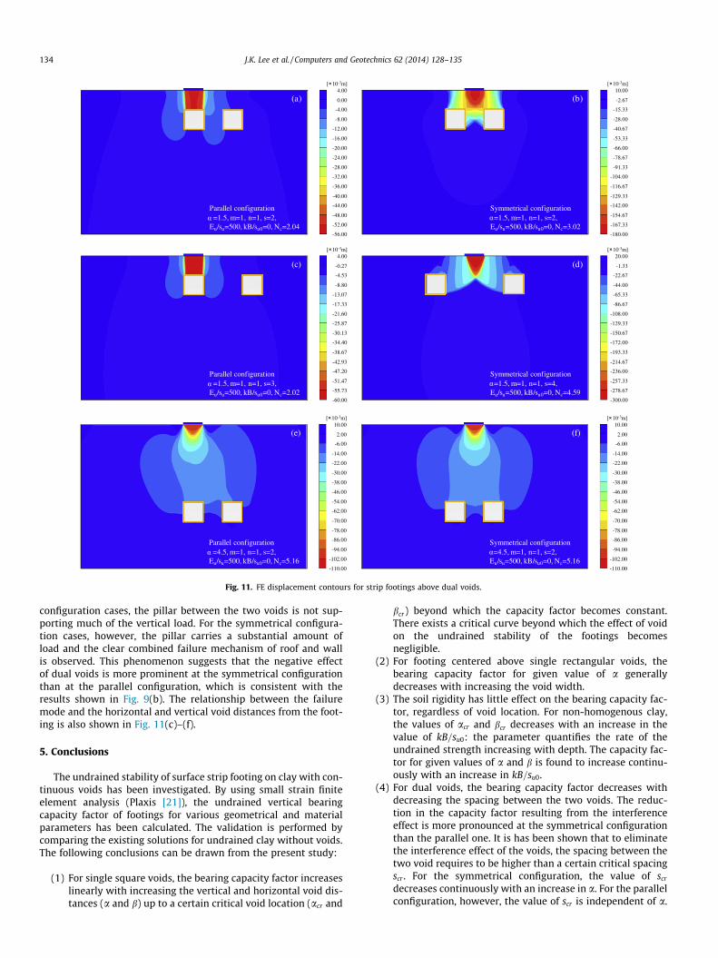
Fig. 11 illustrates the FE displacement contours for strip foot-ings above dual voids in homogeneous clay. The soil displacementnear each void overlapped, which causes the reduction in bearingcapacity, as shown in Figs. 11(a) and (b). When the void spacingis large enough, however, the interaction between the voids doesnot affect the footing performance. In particular, for the parallelconfiguration cases, the footing behaves and collapse as single voidcases. The displacement patterns also show that for the parallel
Parallel configuration=1.5, m=1, n=1, s=2,
Eu/su=500, kB/su0=0, Nc=2.04
(a)4.00
0.00
-4.00
-8.00
-12.00
-16.00
-20.00
-24.00
-28.00
-32.00
-36.00
-40.00
-44.00
-48.00
-52.00
-56.00
[ 10-3m]
Symmetrical configuration=1.5, m=1, n=1, s=2,
Eu/su=500, kB/su0=0, Nc=3.02
(b)10.00
-2.67
-15.33
-28.00
-40.67
-53.33
-66.00
-78.67
-91.33
-104.00
-116.67
-129.33
-142.00
-154.67
-167.33
-180.00
[ 10-3m]
Parallel configuration=1.5, m=1, n=1, s=3,
Eu/su=500, kB/su0=0, Nc=2.02
(c)4.00
-0.27
-4.53
-8.80
-13.07
-17.33
-21.60
-25.87
-30.13
-34.40
-38.67
-42.93
-47.20
-51.47
-55.73
-60.00
[ 10-3m]
Symmetrical configuration=1.5, m=1, n=1, s=4,
Eu/su=500, kB/su0=0, Nc=4.59
(d)20.00
-1.33
-22.67
-44.00
-65.33
-86.67
-108.00
-129.33
-150.67
-172.00
-193.33
-214.67
-236.00
-257.33
-278.67
-300.00
[ 10-3m]
Parallel configuration=4.5, m=1, n=1, s=2,
Eu/su=500, kB/su0=0, Nc=5.16
(e)10.00
2.00
-6.00
-14.00
-22.00
-30.00
-38.00
-46.00
-54.00
-62.00
-70.00
-78.00
-86.00
-94.00
-102.00
-110.00
[ 10-3m]
Symmetrical configuration=4.5, m=1, n=1, s=2,
Eu/su=500, kB/su0=0, Nc=5.16
(f)10.00
2.00
-6.00
-14.00
-22.00
-30.00
-38.00
-46.00
-54.00
-62.00
-70.00
-78.00
-86.00
-94.00
-102.00
-110.00
[ 10-3m]
Fig. 11. FE displacement contours for strip footings above dual voids.
134 J.K. Lee et al. / Computers and Geotechnics 62 (2014) 128–135
configuration cases, the pillar between the two voids is not sup-porting much of the vertical load. For the symmetrical configura-tion cases, however, the pillar carries a substantial amount ofload and the clear combined failure mechanism of roof and wallis observed. This phenomenon suggests that the negative effectof dual voids is more prominent at the symmetrical configurationthan at the parallel configuration, which is consistent with theresults shown in Fig. 9(b). The relationship between the failuremode and the horizontal and vertical void distances from the foot-ing is also shown in Fig. 11(c)–(f).
5. Conclusions
The undrained stability of surface strip footing on clay with con-tinuous voids has been investigated. By using small strain finiteelement analysis (Plaxis [21]), the undrained vertical bearingcapacity factor of footings for various geometrical and materialparameters has been calculated. The validation is performed bycomparing the existing solutions for undrained clay without voids.The following conclusions can be drawn from the present study:
(1) For single square voids, the bearing capacity factor increaseslinearly with increasing the vertical and horizontal void dis-tances (a and b) up to a certain critical void location (acr and
bcr) beyond which the capacity factor becomes constant.There exists a critical curve beyond which the effect of voidon the undrained stability of the footings becomesnegligible.
(2) For footing centered above single rectangular voids, thebearing capacity factor for given value of a generallydecreases with increasing the void width.
(3) The soil rigidity has little effect on the bearing capacity fac-tor, regardless of void location. For non-homogenous clay,the values of acr and bcr decreases with an increase in thevalue of kB=su0: the parameter quantifies the rate of theundrained strength increasing with depth. The capacity fac-tor for given values of a and b is found to increase continu-ously with an increase in kB=su0.
(4) For dual voids, the bearing capacity factor decreases withdecreasing the spacing between the two voids. The reduc-tion in the capacity factor resulting from the interferenceeffect is more pronounced at the symmetrical configurationthan the parallel one. It is has been shown that to eliminatethe interference effect of the voids, the spacing between thetwo void requires to be higher than a certain critical spacingscr . For the symmetrical configuration, the value of scr
decreases continuously with an increase in a. For the parallelconfiguration, however, the value of scr is independent of a.

J.K. Lee et al. / Computers and Geotechnics 62 (2014) 128–135 135
(5) Three distinct types of failure modes are observed in the FEdisplacement contour at the collapse: roof, wall, and com-bined failure mechanisms, which are similar to the previousresults from upper bound solution of limit analysis in theliterature.
Conflict of interest
The authors declare that there is no conflict of interest.
Acknowledgments
The authors acknowledge support in this research for theNational Research Foundation of Korea (NRF) (Grant Nos. 2011-0030040 and 2013R1A6A3A01023199).
References
[1] Andersland OB, Ladanyi B. An introduction to frozen ground engineering. 2nded. New Jersey: John Wiley and Sons; 2004.
[2] Tharp TM. Mechanics of upward propagation of cover collapse sinkhole. EngGeol 1999;52:23–33.
[3] Fam MA, Cascante G, Dusseault MB. Large and small strain properties of sandssubjected to local void increase. J Geotech Geoneviron Eng 2002;128:1018–25.
[4] Park S. Effect of large void formation on strength of cemented glass beads. EngGeol 2012;26:75–81.
[5] Espinoza DN, Kim SH, Santamarina JC. CO2 geological storage – geotechnicalimplications. KSCE J Civil Eng 2011;15:707–19.
[6] Hillel D. Encyclopedia of soils in the environment, vol. 1. New York: AcademicPress; 2004.
[7] Waltham T, Bell F, Culshaw M. Sinkholes and subsidence, karst and cavernousrocks in engineering and construction. New York: Springer; 2005.
[8] Baus RL, Wang MC. Bearing capacity of strip footings above void. J Geotech Eng1983;109:1–14.
[9] Badie A, Wang MC. Stability of spread footing above void in clay. J Geotech Eng1984;110:1591–605.
[10] Wang MC, Badie A. Effect of underground void on foundation stability. JGeotech Eng 1986;111:1008–19.
[11] Wood LA, Larnach WJ. The behavior of footings located above voids, vol. 4. In:Proc 11th int conf soil mech found eng; 1985. p. 273–6.
[12] Wang MC, Hsieh CW. Collapse load of strip footing above circular void. JGeotech Eng 1987;113:511–5.
[13] Al-Tabbaa A, Russell L, O’Reilly M. Model tests of footings above shallowcavities. Ground Eng 1989;22:39–42.
[14] Sreng S, Ueno K, Mochizuki A. Bearing capacity of ground having a void. In:57th JSCE annual meeting; 2002. p. 1221–2 [in Japanese].
[15] Kiyosumi M, Kusakabe O, Ohuchi M, Peng FL. Yielding pressure of spreadfooting above multiple voids. J Geotech Geoneviron Eng 2007;133:1522–31.
[16] Kiyosumi M, Kusakabe O, Ohuchi M. Model tests and analyses of bearingcapacity of strip footing on stiff ground with voids. J Geotech Geoneviron Eng2011;137:363–75.
[17] Meyerhof GG. Some recent research on the bearing capacity of foundations.Can Geotech J 1963;1:16–26.
[18] Prandtl L. Uber die Harte Plasticher Korper. Nachr Ges Wiss. Gottingen MathPhys Kl 1920;12:74–85.
[19] Sloan SW, Assadi A. Undrained stability of a square tunnel in a soil whosestrength in creases linearly with depth. Comput Geotech 1991;12:321–46.
[20] Osman AS, Mair RJ, Bolton MD. On the kinematics of 2D tunnel collapse inundrained clay. Geotechnique 2006;56:585–95.
[21] Brinkgreve RBJ, Engin E, Swolfs WM. Plaxis user’s manual. Netherlands: PlaxisBV; 2012.
[22] Shiau JS, Merifield RS, Lyanmin AV, Sloan SW. Undrained stability of footingson slopes. Int J Geomech 2011;11:381–90.
[23] Georgiadis K. Undrained bearing capacity of strip footings on slopes. J GeotechGeoneviron Eng 2010;136:677–85.
[24] Chen Z, Tho KK, Leung CF, Chow YK. Influence of overburden pressure and soilrigidity on uplift on uplift behavior of square plate anchor in uniform clay.Comput Geotech 2013;52:71–81.
[25] Skempton AW. The bearing capacity of clays. Proc Build Res Cong. Division 1.Part 3; 1951. p. 180–9.
[26] Davis EH, Booker JB. The effect of increasing strength with depth on thebearing capacity of clays. Geotechnique 1973;23:551–63.