Embed Size (px)
Citation preview

/
UNDERWATER TELEMETER FORDEPTH AND TEMPERATURE
Marine Biological Laboratory
)S HOLE, I
SPECIAL SCIENTIFIC REPORT- FISHERIES No. 181
UNITED STATES DEPARTMENT OF THE INTERIOR
FISH AND WILDLIFE SERVICE

EXPLANATORY NOTE
The series embodies results of investigations, usuallyof restricted scope, intended to aid or direct managementor utilization practices and as guides for administrativeor legislative action, it is issued in limited quantities for
official use of Federal, State or cooperating agencies and in
processed form for economy and to avoid delay in publication
\

UNITED STATES DEPARTMENT OF THE INTERIOR, Fred A. Seaton, Secretary
Fish and Wildlife Service, John L. Farley, Director
UNDERWATER TELEMETER FOR
DEPTH AND TEMPERATURE
By
F. H. Stephens, Jr., and F. J. Shea
SPECIAL SCIENTIFIC REPORT - FISHERIES No. 181
Washington, D. C.
June 1956


This report describes the construction of a telemetering depth-
measuring instrument to be used -with midwater trawling devices in
exploratory fishing and gear research. The objective in developing
an instrument of this type is to enable the research fishing vessel
to lower the midwater trawl to the exact depth zone where concentrations
of fish occur, as determined by echo-sounding equipment. The work was
done, under contract with the Fish and Wildlife Service, by the Marine
Laboratory of the University of Miami, F. G. Walton Smith, Director.
An existing and workable device, which was developed by the Woods Hole
Oceanographic Institute and which was described in an unpublished manu-
script by Willard Dow, was redesigned to meet specified requirements.
The authors appreciate the cooperation of Reidar Sand, project leader,
and the staff of the Fish and Wildlife Service station at Coral Gables,
Florida.
//


UNDERWATER TELEMETER FOR DEPTH AND TEMPERATURE
A complete communication system consists of a transmitter, a
transmission medium, and a receiver. In a telemetering system,
the transmitter encodes or translates the desired infoimation into
a foim which may be easily carried by the transmission medium and
which may then be reclaimed at the receiving end. In many cases
where high accuracy or high fidelity is required, serious design
problems are encountered because each link of the telemetering
"chain" has the ability, in one way or another, to scramble the
information being transmitted and to destroy accuracy. Therefore,
it becomes the duty of the design engineer to evaluate the variables
and the sources of error and to use all the facilities at his command
to maintain coherence of the information being transmitted.
Required performance
It was necessary to design an instrument to give continuous
depth information over a range from to 200 fathoms with a resolution
accuracy having an error of not more than + 1 percent. Reliable trans-
mission was required over a distance of 5*000 feet.
The specified performance requirements determined the basic
design of the instrument. In addition to accuracy, stability, oper-
ating distance, and operating time, there were numerous mechanicalaspects to be considered, such as pressure seals and housings. The
following sections present a detailed description of the completedinstrument.
THE TELEMETERING SYSTEM
The telemetering system chosen for the instrument described in
this report is a compromise. The problems of time, cost, and conven-ience weighed heavily in the electronic and mechanical design, andthe finished unit is neither intended nor offered as the ultimate.However, the instrument seems to work exceptionally well and may prove
to be a dependable and flexible device, which, through modificationsor variation, could provide numerous services to studies of oceanographyand marine biology.
In order to obtain high resolution, an FM system was chosen inwhich exceptionally large deviations are used to express the desiredvariable depth. This is the major difference between the presentdesign and that developed by Willard Dow, which used straight primary

frequency regulation to express depth variations. By using FM,
small variations in frequency due to circuit instabilities are
minimized as sources of error. The frequency range chosen for
the carrier is approximately 21 to 36 kilocycles (kc), which
allows an instability of + 150 cycles per second (c.p.s.) as a
+ 1 percent error. Temperature information is transmitted as
amplitude modulation of the carrier with a sine wave tone whose
frequency varies approximately as the temperature,
A Navy-type HBA-6 low-frequency radio receiver was available
for use as a telemetering receiver. It was felt that a 1-percent
system accuracy could be maintained if frequent calibration checks
were made and if extremely high stability were achieved in thetransmitter.
As first planned, the transmission mechanism was to be electri-
cal; that is, the carrier signal was to be propagated electrically
up the uninsulated trawl cable, using the water as a return path.
However, a preliminary trial indicated that this system was impracti-cal because of a high electrical noise level aboard the M/V GERDA
and because a failure of electrical connections between the tele-
meter transmitter and the trawl cable. Being pressed for time,
this method was not pursued further and, after consultation with
Dow, an acoustic link was employed. A choice of transducers allowedthe incorporation of directional units with their attendant effective
transmitting and receiving power gain. In addition, the directional
receiving transducer was able to discriminate against undesirablesounds, such as screw noises. Dow outlined a system in which thereceiving transducer was kept aimed in the general direction of thetransmitter by sliding it a short distance down the trawl wire, usingthe wire angle for alignment. (See fig. 1.)
SHIPS WAKE
0IRECTI0NAL ~~
RECEIVING / TRAWL CABLETRAWSOUCEF^— ~- _^_ TEl LHETER MIOWATCIf
~__^ ^_$ TRANSMITTER WET
3I6NAL CONE ^c*"^"^^DIRECTIONAL
TRANSMITTINGTRANSDUCER
Fig, 1, Diagram of Telemeter System
2
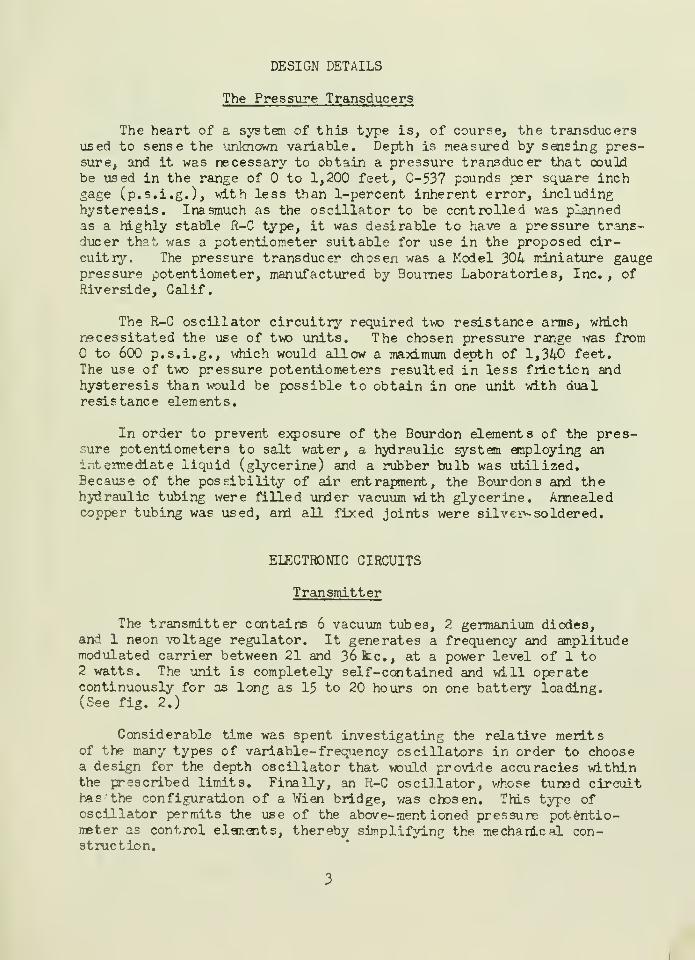
DESIGN DETAILS
The Pressure Transducers
The heart of a system, of this type is, of course, the transducersused to sense the unknown variable. Depth is measured by sensing pres-sure, and it was necessary to obtain a pressure transducer that couldbe used in the range of to 1,200 feet, 0-537 pounds per square inchgage (p.s.i.g.), with less than 1-percent inherent error, includinghysteresis. Inasmuch as the oscillator to be controlled was plannedas a highly stable R-C type, it was desirable to have a pressure trans-ducer th?.t was a potentiometer suitable for use in the proposed cir-cuitry. The pressure transducer chosen was a Model 304 miniature gaugepressure potentiometer, manufactured by Bournes Laboratories, Inc. , ofRiverside, Calif.
The R-C oscillator circuitry required two resistance arms, whichnecessitated the use of two units. The chosen pressure range was from
to 600 p.s.i.g., which would allow a maximum depth of 1,340 feet.The use of two pressure potentiometers resulted in less friction andhysteresis than would be possible to obtain in one unit with dualresistance elements.
In order to prevent exposure of the Bourdon elements of the pres-sure potentiometers to salt water, a hydraulic system employing anintermediate liquid (glycerine) and a rubber bulb was utilized.Because of the possibility of air entrapment, the Bourdons and thehydraulic tubing were filled under vacuum with glycerine. Annealedcopper tubing was used, and all fixed joints were silver soldered.
ELECTRONIC CIRCUITS
Transmitter
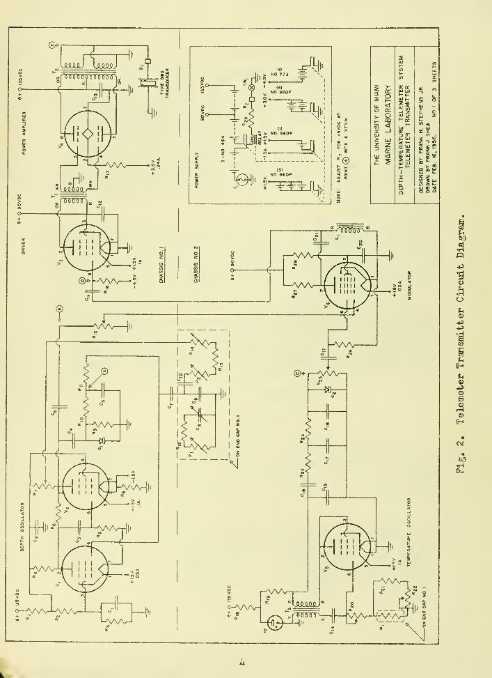
The transmitter contains 6 vacuum tubes, 2 germanium diodes,and 1 neon voltage regulator. It generates a frequency and amplitudemodulated carrier between 21 and 36 kc., at a power level of 1 to2 watts. The unit is completely self-contained and will operatecontinuously for as long as 15 to 20 hours on one battery loading.(See fig. 2.)
Considerable time was spent investigating the relative meritsof the many types of variable- frequency oscillators in order to choosea design for the depth oscillator that would provide accuracies withinthe prescribed limits. Finally, an R-C oscillator, whose tuned circuithas the configuration of a Wien bridge, was chosen. This type ofoscillator permits the use of the above-mentioned pressure potentio-meter as control elar.ents, thereby simplifying the mechanical con-struction.
e>
ssauu
-6
Tinnrirpwinnr O =>O
Ul M' 3. Z> «
4i'
Hi"'< t-rr Ui^ sQ. l±J
2 -J
UJ UlK -I
I
z -» m5*2?
M < t-y c 4O O Q
^rsTrinr^—
,
r—wv
"—'wv-
®
AAA/ ||i
rr" A^V
<
-+
-AAA-
o—VvVW' c-AVv- .OOOQOJ
"-AAA^-l ^pnnnrr-

Several breadboard models of Wien-bridge oscillators were con-
structed; however, all of them were found to be very sensitive to
power-supply fluctuations. Batteries used in this instrument should
have an end-point voltage about 20-percent down, therefore, such a
degree of sensitivity on the part of the oscillator would make the
circuits unusable during a power fluctuation. Frequency instabili-
ties of several kilocycles were noted where both plate and heater
supplies were varied, and the errors compounded themselves.
A new oscillator design, extremely stable with regard to power-
supply fluctuations, was finally evolved. In this design, the proper
use of negative feedback and the use of a variable-mu pentode for
amplitude control practically eliminated frequency shift resulting
from supply-voltage changes. 3y using heater-type tubes (6SK7-6V6),
it was possible to maintain frequency (within 20 c.p.s.) even though
plate-supply voltage was more than doubled. In addition, amplitude
and frequency were constant for more than 10 seconds after the heater
current was interrupted; after 10 seconds, the oscillations ceased
abruptly.
Although it was necessary to redesign this oscillator for operation
with miniature battery-type tubes, stability was sacrificed to only a
very slight degree. It was necessary to provide a self-biased resis-
tive cathode for the second amplifier tube, which, when using battery
tubes, required an isolated and separate battery. Because of currentdrawn by the rectifier in the automatic-gain -control (a.g.c.) circuit,
the output waveform for this particular oscillator is not so good asthat obtainable with a conventional T
:,rien-bridge oscillator. Howsver,
a few-percent distortion in this service is entirely negligible.
The depth-frequency characteristics of the completed circuit willbe a function of the degree of linearity of the pressure potentio-meters. The Wien-bridge oscillator has an operating frequency thatis about equal to l/2lfRQ when R and C are the resistance and capa-citance of the component parts of the reactive arms of the bridge.Variation of frequency is linear with respect to changes in R or C.
Rough measurements of linearity of the oscillator indicate a valueof more than 3 percent over the ant ire range.
The operation of the telemeter may be described as follows:
In referring to the schematic diagram (fig. 2), tubes V- and
Vp (type 1T4 and 3V4, respectively) are used as the depth oscillator,described above. They are located on the same chassis as Vo and V,
and comprise a necessary two-stage amplifier of the R-C oscillator.The phase- shifting network is mounted on onr> end-cap of the instrumentand consists of the two pressure potentiometers, three resistors, andthree capacitors. One of these resistors, R]i , and one capacitor,Cg, are adjustable and function as high-frequency and low- frequency

calibration adjustments, respectively. G-, (type 1N54-A germaniumdiode) functions as the a.g.c. rectifier and supplies the controlbias for the variable mu amplifier, V-^. Positive feedback is
adjustable by means of R~, which, of course, sets the level of
oscillation. This is adjusted so as to provide -5 volts, d»c. at
point A, as measured with a vacuum-tube voltmeter. This adjustmentis made at the lowest operating frequency.
Vq (1R5) follows V-|_ and V2 and serves two purposes: it acts as
a buffer amplifier between the oscillator and driver, V^, and it is
ussd as a modulator that mixes the depth and temperature signals sothey may be transmitted together. The plate circuit of V^ containsa single section—constant k, T high-pass filter—which has a low-frequency cutoff of about 10 kc. It prevents the modulating signal(about 200 to 800 c.p.s.) from appearing at the grid of the class-Adriver, Vo. The carrier level is adjusted independently of modulationlevel by R-jr and is set while observing the output waveform at thesecondary of T2 when it is properly loaded.
Vo (3V4) operates as a class-A amplifier and supplies the energynecessary to properly drive the grid of Vi , the U6GT class-B poweramplifier.
The class-A driver and class-B output transformers, T-, and T2 ,
and the filter reactor, L^, were designed and wound at the "MarineLaboratory. The modulating signal is supplied by the temperatureoscillator, Vr, a 3V4 blocking oscillator. The temperature-sensingelement is a type 51R2 thermistor made by Victors'- Engineering Co.It is encased in a special oil-filled brass housing, which is screwedinto the end cap of the instrument. High -temperature and low-temper-ature limit calibration adjustments are provided by R20 and %2>respectively. The "sawtooth" output from Vc is shaped by an R-6 net-work, described above. In reality, this is not an undesirable effect.Modulation would be increased in colder water., which, in general,would be deepest. A slight saving in battery power may result atshallow depths, where the water is warmest.
Of course, other information could be impressed on thecarrier by means of the moduLator, which, when tested in the labor-atory, was fairly linear. Adjustment of modulation percentage,independently of carrier level, may bo made by R2r. This adjv«3tmentshould be made at the low-temperature limit, while observing outputwaveform at the secondary of T2 in order to avoid overload, whichwould cause a multiplicity of sidebands and make it difficult toidentify the carrier on. the telemeter receiver.
The transducer is affixed to the telemeter housing with a cLianp
that allows positioning at various angles in order to pre-set its
transmitting direction. The transducer is a Navy-type QBG crystal
unit, which, because of its size, shows directional characteristics
and power gain. It was chosen because of these characteristics, and,
although its resonant point lies at about 26 kc., it wa3 thought that
sufficient energy would be radiated over the desired range (21 to
36 kc.) if it were fed at 150 ohms impedance. The 26 kc. high-efficiency point would be near the proposed optimum operating depth
(100 fathoms).
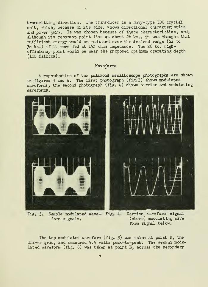
Waveforms
A reproduction of two polaroid oscilloscope photographs are shown
in figures 3 and 4. The first photograph (fig. 3) shows modulated
waveforms j the second photograph (fig. 4) shows carrier and modulating
waveforms.
Fig, 3» Sample modulated wave— Fig, 4*
form signals
.
Carrier waveform signal(above) modulating wave
form signal below.
The top modulated waveform (fig, 3) was taken at point D, the
driver grid, and measured 9»5 volts peak-to-peak. The second modu-
lated waveform (fig. 3) was taken at point E, across the secondary

of T2 when loaded by 150 ohms. It shows a compression of modulationdue to non-linearity in the class-B anplifier, V, , at the 2-watt
level. Voltage at this point is about 50 volts peak-to-peak.
The 21-kc. carrier is shown at the top of figure 4 as it appears
at the mixer grid, point B. The voltage at this point is 10 volts
peak-to-peak at 21 kc. The slight distortion caused by the a.g.cdiode can be seen on positive waveform peaks. The fuzzy waveformpeaks are due to coupling of a small amount of modulating voltage
through the B+line. Increasing the size of C2 > and substituting a
choke for R,, would eliminate this problem; however, no deleterious
effects upon the operation were noted, and the necessary extra space
was not available. The depth oscillator showed a very slight tendencyto lock to harmonics of the temperature or modulating waveform and
when waveform peaks coincided; however, pulling was very slight.
The modulating waveform shown at the bottom of the second polaroidphotograph (fig. 4) was taken at point C, and it measured 3.2 voltspeak-to-peak at 520 c.p.s. It is a modified sawtooth, which is alteredby the network containing R
2v -^24* ^2 (
5> ^17* ^18' an<^ ^2*
Receiver
The telemetering receiver used in this system is a Navy-modelR3A-6, low-frequency, radio receiver type CJT 463OO. It is used inan unaltered condition; however, the system required auxiliary re-ceiving equipmsni. This auxiliary equipment consists of a cathode-follower transducer isolation amplifier and a low-noise, high-gainpreamplifier. These units are described below.
A cathode- follower amplifier, V„ (6AH6), is contained in thereceiving transducer housing and is powered through the multi-conductercable connecting it to the preamplifier at the receiver. Vy is usedto isolate the crystal receiving transducer from the low-impedancecable connecting it to the preamplifier, and thus it prevents loading.This tube also provides a low-impedance source to drive the bandpassfilter located in the preamplifier, An electrical schematic drawingof these unit 3 is shovn in figure 5.
A preamplifier consists of two tube3, Vg and VQ . Vg is a6BK7A, which is used as a high-gain, low-noise, cascade amplifier,and Vo. is a 12AU77j which is used as a triode amplifier and cathode-follcwer output. A bandpass filter is used at the input- of the unitto exclude undesirable electrical voltages outside the frequency rangeused for telemetry and to prevent cross-modulation and generation ofunnecessary interference. The bandpass of this filter is 1.5 to 100 kc,
8

^Ws^i
nm
H(-
*ce
<D
CECNJ
O-
III
-nnnr>—|f-•n CD lv
oCM
m10
Mill'jooo o
UJ
m<
\c >-o-
xo-
at
n
CK -o >
-O X
Hi'
10 a:*]
r ^ ^
c:
CE

vMch vdll exclude power and low-frequency radio signals. The useof the preamplifier was to increase the signal-to-noise ratio ofthe receiving system and to provide the utmost sensitivity possible.
The receiving transducer is a type MI-2 mine hydrophone and,although no information was available concerning its use of frequencyresponse, it appears to be suitable over the 20- to 40-kc. range.It consists of a Rochelle-salt array, about 3-1/2 inches in diameter,which, when considered as a piston, would have a useful directivitypattern at these frequencies. It is fitted with a large flangedpipe, capped at one end, which contains the 6AH6 cathode-followeramplifier. In use, this assembly is suspended over the stern to apoint just below the ship's wake.
Fig. 6. Telemeter transmitter and receiving hydrophone
MECHANICAL DESIGN
Telemeter Case
This consists of a 5~l/4-inch-inside-diameter (I.D.) steelcylinder, 27-1/4 inches long with a l/4-inch-thi ck wall. The insidesurfaces of the ends are machined and ground. A l/4-inch relievedlip on each end has been machined to prevent damage to the 0-ringsduring assembly of the instrument. There are also three anchorpoints on each end of the case for attachment of L-shaped clamps toretain the end caps.
End Caps
(a) The end caps are machined from cast brass blanks
.
caps are 5-3/4 inches wide on the 3/8-inch-thick flange and areThe
10
5-1/4 inches wide on the l-l/8-inch barrel. Each cap is machinedfor two O-rings, type PRP-902-54 or National 622754. The O-ringseal was designed for a 1,500 p.s.i.g. non-moving seal. Becausethe inside diameter of the telemeter case did not conform to thestandard 0-ring size, it was necessary to recompute the groove,
ring clearance, ring cross section, and similar information. Thisis for only one ring per end-cap; the second ring was added forsafety.
(b) One end-cap top is blank to allow for the transducerpivot clearance. The other end-cap top contains the depth and temper-ature-sensing elements and the two feed-th roughs.
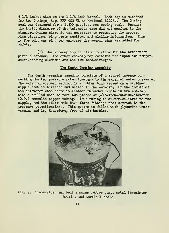
The Depth-Sensing Assembly
The depth -sensing assembly consists of a sealed passage con-necting the two pressure potentiometers to the external water pressure.The external exposed section is a rubber bulb served on a machinednipple that is threaded and sealed in the end-cap. On the inside ofthe telemeter case there is another threaded nipple in the end-capwith a drilled head to take two pieces of 3/l6-inch-out side-diameter(O.D.) annealed copper tubing. This tubing is silver-soldered to thenipple, and the other ends have flare fittings that connect to thepressure potentiometers. This system is filled with glycerine undervacuum, and is, therefore, free of air bubbles.
Fig. 7. Transmitter end bell showing rubber pump, metal thermistorhousing and terminal seals.
11

The Temperature-Sensing Element
This sensing element is a 51R2 thermistor contained in a brass-walled cylinder that is threaded into the end-cap. This brass cylinder
ha3 a 13/32-inch O.D., and is 1-1/2 inches long. It is bored in two
stages, one to take the insulated thermistor and the other to take the
threaded bakelite plug. The bakelite feed-through plug is drilled to
take the two thermistor wires. The cavity containing the thermistor
is filled with mineral oil, the bakelite plug is run in, then the feed-
throughs are sealed off.
The Feed-Throughs
These are for the signal switch and the water switch, and are
located on the above-mentioned end-cap. Both feed-throughs are
identical in construction; therefore, only one will be described here.
A 3/4-inc h-diameter hole, 1-1/8 inches deep, is bored into the end-cap,
which houses all of the parts in the feed-through assembly. Startingat the bottom of the hole, a lucite disk (0. 740-inch diameter, 3/8-inchthick) containing a clearance hole through the center for a l/8-inch-dianeter brass rod 1-1/2 inches long, and a groove mid-way up the side
of the perimeter for a PRP-902-11 O-ring, is placed in the positionfirst. This forms a seal between the assembly and the wall of the hole
in the end-cap. After this seal, a brass disk (0. 625-inch diameter,
l/4-inch thick) with a l/8-inch shaft anchored to the center of the
bottom, and a PRP-902-7 O-ring in the peripheral area of the bottomside of the disk, is placed on the lucite disk. The l/8-inch brassrod is insulated, where it passes through the body of the end-cap,with a length of insulating sleeve. The insulated lead is connectedto the top of this disk. The lucite disk and the brass disk, withtheir associated O-ring s, form the water-tight seal for the electricalfeed-through. Above the brass disk is another lucite disk (0.72 5-inchdiameter, l/4-inch thick) with a l/l6-inch hole through it for the
insulated lead and attaching plate. This disk serves as an insulatorbetween the brass disk and the threaded hex-head plug (3/4 inch, 14thread, by 3/8 inch) that completes the assembly. This plug has a
0.102-inch-diameter hole through it for the insulated lead, and abored brass sleeve (3/l6-inch O.D., 3/4 inch long) silver-solderedon top, concentric with the hole, to serve as a mounting post for apiece of surgical rubber tubing (l/4-inch O.D., 3 inches long). Therubber tubing, or boot, serves as a re.swrvoir for the silicone high-vacuum grease and as a stiffener for the wire to distribute Hexing,.The feed-throughs and rubber tubing are packed with vacuum grease,
carefully excluding all air bubble?, then the tubing is served offtightly at both ends. These feed-throughs are designed to withstanda pressure of 1,500 p.s.i.j however, to increase the safety factorwould require enlarging the feed-through assemblies to accomodate theadditional 0-rings, which would then cause numerous design complications.
12
g.

The Streamlined Nose-Piece
The wooden nose-piece was designed to protect and direct a balanced
flow of seawater on the end cap, which houses the sensing elements when
the telemeter was being towed through the water with the sensing elements
facing forward. This nose-piece houses the seawater sxvitch, which is a 1/4-
inch O.D. lucite rod with a heavy brass slug where the insulated wire
from the battery relay is attached. The electrical circuit i3 completed
whenever water completes the circuit between the brass slug and the metal
telemeter housing. The exposed end of the relay wire is coated with
either rubber cement or 3^ Scotch Fill.
Fittings
(a) The transducer mount is constructed of l/4- by l-l/2-inchbrass rectangular stock. It is a two-piece band with brass spacer blocks
to carry the supporting arms, which hold the type QBG transducer. The
directional adjustment is approximately -15° to +45° for the axis of thetransducer.
(b) The hangers are also constructed of l/4- by l-l/2-inchbrass rectangular stock, and both are one-piece-type clamp bands. Onehanger has a single mounting arm and shackle, and the other hanger has
two mounting arms and shackles placed diametrically opposite each other,
(c) The three-fin tail assembly is constructed of l/4- byl/4-inch brass rectangular stock framework with 0.017-inch sheet brass.
These three fins are mounted on a two-piece band (l/8- by 1-inch brassrectangular stock) forward, and are held fi roily aft to the telemtercase with a band (l/l6- by 1-inch brass rectangular stock) encirclingthe circumference of the fins and anchored at the three points on the
telemeter case.
This arrangement will allow a nurrber of mounting possibilities:
(1) Towing with fins and a bridle.
(2) Towing with fins, bridle, floatation equipment,and ballast on other hanger.
(3) Attached to trawl cable with both hangers.
(4) Fount ed on trawl wings with both hangers.
(5) Mounted in the mouth of trawl net with both hanfers.
14

Hydrophone Case
This is a 6-inch I.D. steel-wall pipe, 18 inches long with a
l/4-inch-ttdck wall. One end of this pipe is threaded, and an end-
cap is firmly screwed on; then a complete brazed joint is made around
the threaded joint. On the other end, a 6-3/16- by 1-inch brass
flange is brazed onto the pipe. This flange is machined for a PRP~
902-64 0-ring, eight 7/l6-inch stud holes, and a standard 5-inch non-
tapered pips thread on the inside diameter. It will accomodate anMI-2 mine hydrophone at present, but other hydrophones may be used
by attaching custom-made adapters on the 5-inch non-tapered pipe
thread.
A No. CC1045 H.H, Buggie-cable feed-through gland is mounted on
the end-cap for the power and sigial cable.
A treated wooden nose piece fits on the pipe end-cap for stream-
lining purposes, and is banded with 3/8-inch oval brass.
The matching amplifier is shock mounted to the back cover of
the MI-2 mine hydrophone.
The hangers (l/4- by 1-inch brass rectangular stock) are clamp-
type bands which attach the hydrophone assenfcly to the trawl cable.
The hangers can mount marlin-served shackles, or guarded sheaves can
be fabricated if the cable-shackle noise level should be annoying.
Batteries
The battery section of the telemeter contains Eveready batteries
No. 484, No. 960P, and No. 773. It is necessary to keep cardboardspacers between (l) the No. 484 batteries to allow wire and plugclearance and (2) the No. 96OP to provide insulation between bottomof cells and chassis ground, wires, and plugs. Placing insulatingtape on the bottom of the cells provide an additional safety factoragainst shorts.
Maintenance
It must be emphasized that for the proper performance of thisequipment, as far as water leaks are concerned;, the O-ring seals,feed-th roughs, and rubber tubing must be properly inspected, cleaned,
and coated or packed with silicone high-vacuum grease before theinstrument is pit into operation.
After each use of the instrument, the O-rings that seal the end
caps into the telemeter case and the O-ring that seals the MI-2 minehydrophone must be inspected, cleaned, and re-coated before re-use or
15

storage. Periodic inspections of the feed-through assemblies will
be necessary. Re-packing should be determined by condition of
assemblies.
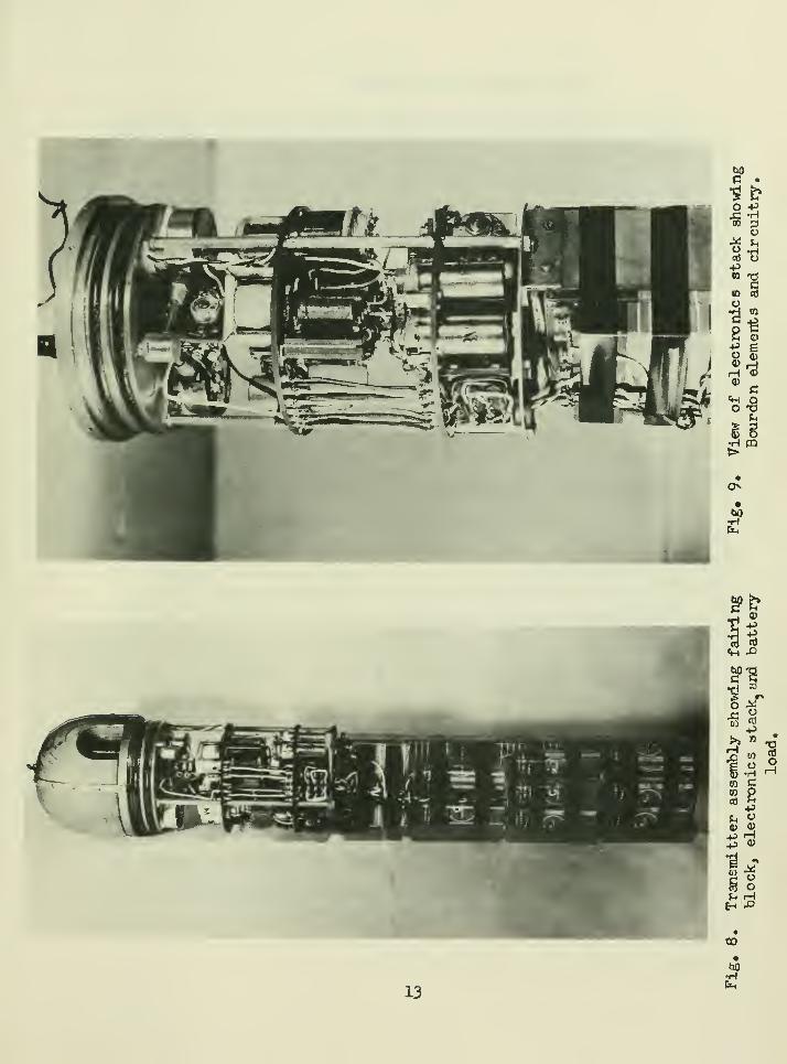
Fig. 10. Telemeter assembly showing transmitter, receiving hydro-
phone, power supply, pre-amplifier and RBA-6 receiver.
TRIALS AND TESTS
Two tests of the completed instrument were run: a test fordistance, and a test for depth.
Distance and Directivity
A shallow-water distance test was run in Government Cut at MiamiBeach, Fla. The receiver and receiving transducer were on shore ata vantage point enabling a clear shot across the channel for approxi-mately 1.2 miles. During the test, there was considerable noise fromthe various power boats in the inmediate vicinity, and conditions wereby no means ideal. The telemeter transmitter was suspended from asmall motor launch to a depth of approximately 7 feet. Excellentsignals were received as far as 1 mile, and extremely strong signalswere received at 3,000 feet. Tone modulation was readable at all times.
16

Received signal voltages at the preamplifier impub measured about 100
and 500 microvolts (u.v.) at 1 mile. These levels were at least 20
decibels (db) above the ambient noise levels at the receiver output.
A measurement of receiver-system noise showed that the self- noise ofthe receiver-preamplifier combination is 6 db below 0.09 >i.v. at 21 kc,which shows a tremendous margin of sensitivity for use in quiet waters.
Of course, use in oceanic water will afford much better ambient noise
conditions than Biscayne Bay, which was full of motor vessels and bio-
logical noisemakers.
As expected, multiple-path transmission caused extreme variation
in signal strengths during this test, and it was difficult to establish
exact figures for directivity. The fading was strikingly similar inamplitude and period to that experienced in low- or medium-frequency
radio transmissions at or near ground-wave limits. Amplitude excursions
of 20 db were noticed under certain conditions.
At distances of approximately 1 mile, variations in the positionof the transmitting transducer within a 40° horizontal angle did not
seriously affect the received signal. Transmission, at times, was
obtainable with reflected energy from the large stone breakwaters
100 feet behind the transmitter. At 1,500-foot range, overload of the
receiver was experienced and extremely strong signals were received
regardless of the transmitter's direction. Test personnel aboard the
motor launch were able to hear the received tone from the receiver
loudspeaker on shore, a distance of 2,000 feet.
The KE-2 hydrophone assembly was suspended by rope from a pole
at the seawall at the southeast corner of the Coast Guard base. Move-ment of this unit to determine directivity characteristics indicated,as would be expected, a much broader pattern. The receiving patternseemed to be about 20° or 30° wider than that of the QBG transducertransmitter.
The above observations were made at 21 kc. (the surface frequency).
Transducer gain will be greater at the higher frequencies, due to thesharper directivity patterns expected, and the figures given here mayvary widely.
Depth
A trip to sea aboard the K/V GERDA was made for depth tests in
order to check pressure housing and seals of the telemeter transmitter.Inasmuch as seas were moderate and there was a wind of about 10 knots,
it was impossible to lower the telemeter without a considerable cable
angle. This angle increased with depth and made it impose ibis to
ascertain the exact depth of the telemeter transmitter. Therefore,
17
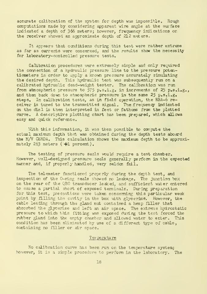
accurate calibration of the system for depth was impossible. Roughcomputations made by considering apparent wire angle at the surfaceindicated a depth of 366 meters; however, frequency indications onthe receiver showed an approximate depth of 212 meters.
It appears that conditions during this test were rather extraneas far as currents were concerned, and the results show the necessityfor laboratory-controlled pressure tests.
Calibration procedures were extremely simple and only requiredthe connection of a hydraulic pressure line to the pressure poten-tiometers in order to apply a known pressure accurately simulatingthe desired depth. This hydraulic te3t was subsequently run on a
calibrated hydraulic dead-weight tester. The calibration was runfrom atmospheric pressure to 575 p.s.i.g. in increments of 25 p.s.i.g.,and then back down to atmospheric pressure in the same 25 p.s.i.g.steps. In calibration tests, as in field operation, the RBA-6 re-ceiver is tuned to the transmitted signal. The frequency indicateden the dial is then interpreted in feet or fathoms from the plottedcurve. A descriptive plotting chart has been prepared, which allowseasy and quick reference.
With this information, it was then possible to compute theactual maximum depth that was obtained during the depth tests aboardthe M/V GERDA. This calculation shows the maximum depth to be approxi-mately 263 meters ( +1 percent).
The testing of pressure seals would require a test chamber.However, well-designed pressure seals generally perform in the expectedmanner and, if properly handled, very seldcm fail.
The telemeter functioned properly during the depth test, andinspection of the O-ring seals showed no leakage. The junction boxon the rear of the QBG transducer leaked, and sufficient water enteredto cause a partial short of exposed terminals. During preparationfor this test, pre cauti oris were taken concerning this particular weakpoint by filling the cavity in the box with glycerine. However, thecable leading through the gland nut contained a hemp filler thatabsorbed the glycerine and left an air space. The extreme hydrostaticpressure to which this fitting was exposed during the test forced therubber gland into the empty chamber and allowed water to enter. Thiscondition has been eliminated by use of a different type of cable,containing no filler or air space.
Tem perature
No calibration curve has been run on the temperature system;however, it is a simple procedure to perform in the laboratory. The
18

telemeter can be suspended upside down with the sensing element
immersed in a controllable temperature bath; then, as the bath is
altered, an audio oscillator is adjusted for zero beat against the
nodulated tone of the RBA-6 receiver. After a number of points havebeen recorded, a curve can be plotted to serve as the temperature-modulated tone- conversion table.
REFERENCES
1. DOW, Willard. Underwater Telemetry: A Telemetering DepthMeter, Woods Hole Oceanographic Institution Ref. 54-39*(Unpublished Manuscript.)
2. TERMAN, F. E., and J. K. Pettit. Electronic Measurements,McGraw-Hill Book Co,, Inc. 1952, New York, N. Y.
19
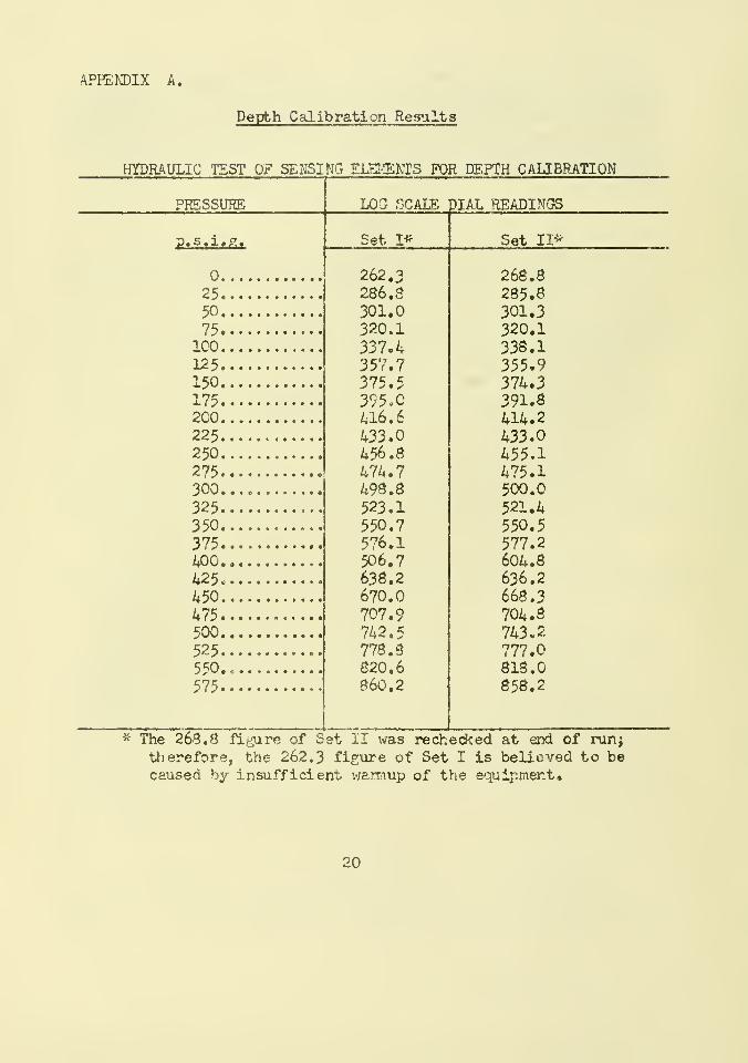
APPENDIX A.
Depth Calibration Results
HYDRAULIC TEST OF SENSING ELEMENTS FOR DEPTH CALIBRATION
PRESSURE LOG SCALE DIAL READINGS
p.s.i.g.
25
50
75100125150175200225250275 ,
300325350375400425*
450475500525
575
Set I*
262.3286. S301.0320.1337.4357.7375.5395.0416.6433.0456.8474.7498.8523.1550.7576.1506.7638.2670.0707.9742.5778.8820.6860.2
Set II*
268.8285.8301.3320.1338.1355.9374.3391.8414.2433.0455.1475.1500.0521.4550.5577.2604.8636.2668.3704.8743.2777.0818.0858.2
* The 268.8 figure of Set II was rechecked at end of run;
therefore, the 262.3 figure of Set I is believed to becaused by insufficient waimup of the equipment.
20
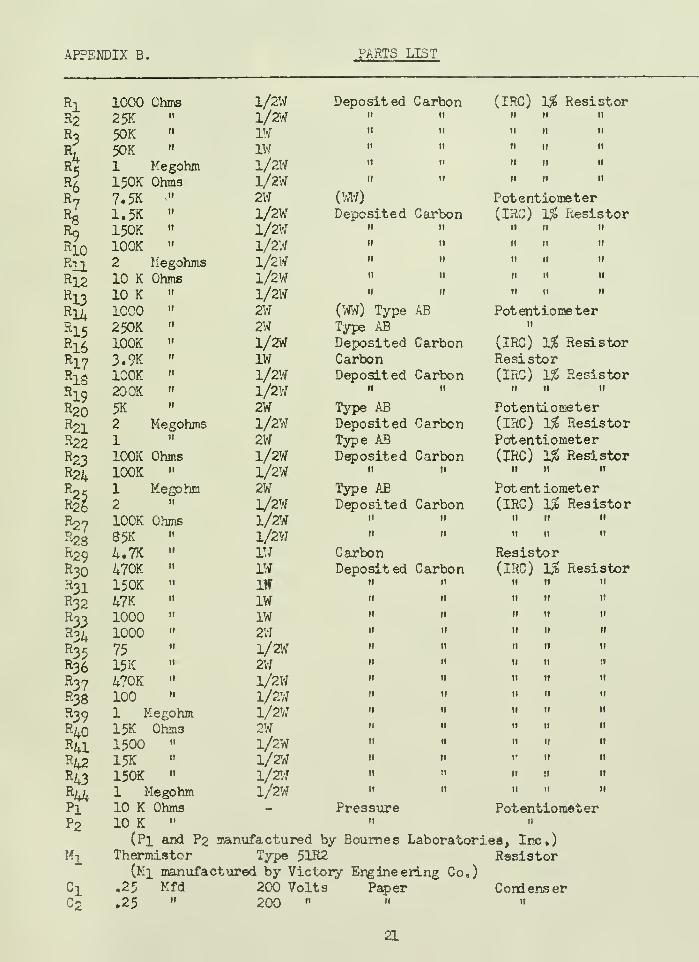
APPENDIX B.
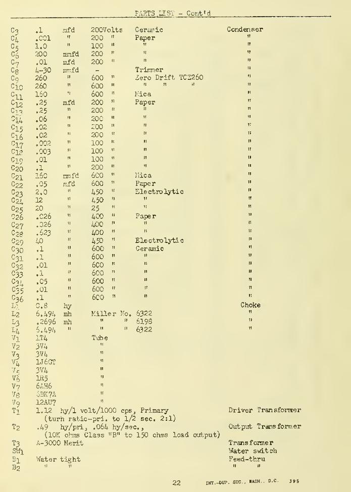
FARTS LIST Cont'd
C?C4
cb
C8c9
cio
c11
u12c13
c15Ci6C17Ci8C19C20C21C22c23^24C25C26
027C28
-29C3Oc31c32C33c34C35
Li
L2
^3L4viV2
7cv£V?
v9Tl
T2
T3SWl
BlB2
mfd11
11
mmfdmfdmmfd
11
11
n
mfd11
n
ti
11
11
ti
n
11
nmfdmfd
11
ti
it
n
11
11
11
11
I!
II
it
II
II
II
fay
mhmh
200Volts200 "
100200200
Cerairic
Paper.1
.0011.0200.014-30260260160.25
.25
.06
.02
.02
.002
.003
.01
.1
160
.05
2.012
20.026
.026
.623
40.1
.1
.01
.1
.05
.01
.1
0.86.4%.2696
6.4941T43V43V41J60T3V4IR56AH663K7A12AU71.12 hy/1 volt/1000 cps, Primary
(turn ratio -pri, to l/2 sec. 2:1)
.49 hy/pri, .064 hy/sec.
,
(10K ohms Class "B" to 150 ohms load output)A-3000 Merit
Water tightti 11
600600600200200200200200100100100200600600
45045025400400400450600600600600600600600
11
ti
it
it
11
11
ti
ti
11
11
11
11
11
11
11
11
11
11
11
11
n
ti
it
11
11
it
it
it
ti
ti
11
11
it
TrinmerZero Drift TCZ260
it ti 11
MicaPaper
11
11
n
ti
11
11
11
TI
I lie a
PaperElectrolytic
11
11
Paperit
11
ElectrolyticCeramic
it
it
it
it
n
11
Miller No. 6322» « 6196" " 6322
Tube11
n
11
11
11
11
11
11
Condenser11
11
11
ti
it
it
ti
11
tt
it
«i
ti
tt
11
it
ti
11
11
11
11
11
11
11
it
ti
11
tt
11
11
11
11
11
11
Choke11
tt
ti
Driver Transformer
Output Transformer
TransformerWater switchFeed-thru
11 u
22 INT.-DUP. SEC. WASH. D.C. 395

..-^Maamillll
?WSE 01712