Embed Size (px)
Citation preview

Understanding X-rays:The electromagnetic spectrum
BeKa
0.11 keV
11.27 nm
ULa
13.61 keV
0.09 nm
1
E = hn = hcl
where, E : energy, h : Planck's constant, n : frequency
c : speed of light in vacuum, l : wavelength
E (keV) = hcl
= 1.2398/l (nm) or, l (nm) = h cE
= 1.2398/E (keV)
Examples:
lBeKa = 11.27 nm; Hence, EBeKa = 1.2398/11.27 = 0.11 keV
EULa = 13.61 keV; Hence, lULa = 1.2398/13.61 = 0.09 nm

X-ray spectrum
Characteristic X-rays
Bremmstrahlung
(continuum) X-rays
Ti Ka
Fe Ka
Ti KbFe Kb
Wavelength
Energy
Intensity
2

Characteristic X-ray generation
Inner shell ionization through inelastic scattering
Overvoltage, U = E/Ec , > 1
E : electron beam energyEc : critical excitation energy
(or, ionization energy)of shell in target atom
(Ka)
3

Condition for ionization: Overvoltage
Best analytical condition, U≈5
cro
ss-s
ecti
on o
f io
niz
ati
on
4

X-ray energies
X-ray Electron transition Energy
Ka LII+III to KI EKa = Ec(KI)- Ec(LII+III)
Kb MIII to KI EKb = Ec(KI)- Ec(MIII)
La MIV+V to LIII ELa = Ec(LIII)- Ec(MIV+V)
Ma NVII to MV EMa = Ec(MV) - Ec(NVII)
5

EKa = Ec(K) - Ec(L)
Rearrange Ec(K) = EKa + Ec(L)
Substitute Ec(L) = ELa + Ec(M) = EKa + (ELa + Ec(M))
Substitute Ec(M) = EMa + Ec(N) = EKa + ELa + (EMa + Ec(N))
Therefore, Ec(K) ≈ EKa + ELa + EMa
X-ray energy and critical excitation energy
What is the energy
required to excite UKa?
Critical excitation energy
of the U K-shell, Ec(K)
Ec(K) ≈ 98.4 + 13.6 + 3.2
≈ 115.2 keV
Required energy > 115.2 keV
6

Maximum x-ray production depth (range) 7
(Castaing’s formula)
RX-ray = x-ray range (maximum depth)
E = electron beam energy
Ec = critical excitation energy of target atomic shell
A = atomic weight
r = density
Z = atomic number

Maximum x-ray production depth (range) 8

Electron range versus X-ray range
x-ray rangeelectron range
The characteristic x-ray range is always smaller
than the electron range
E = beam energy
Ec = critical excitation
energy of sample
atomic shell
Z = atomic number
A = atomic weight
r = density
9

10X-ray depth-distribution: the f(rz) function
f(Drz) = intensity from a free standing layer of thickness ‘z’
f(rz) at depth z = intensity from depth ‘z’ divided by f(Drz)
where, r = density, and z = depth

Continuum X-ray generation
Produced by deceleration of beam electrons in the electrostatic field of target atoms
Energy lost by beam electrons is converted to x-ray
(Maximum energy of continuum x-rays = electron beam energy)
Electronbeam
11

Continuum X-rays: background intensity
Increases with sample atomic number
12
High-Z sample
(Ca-Fe rich)
High background
Low-Z sample
(Ca-Fe poor)
Low background

crystal
detector
Wavelength Dispersive Spectrometer (WDS) 13

Wavelength Dispersive Spectrometer (WDS)
Bragg’s Law: nl = 2d sin q
n: order of diffraction
l: wavelength of x-ray
d: lattice spacing in diffracting crystal
q: angle of incidence or diffraction
L: distance between sample and crystal
R: radius of focusing (Rowland) circle
d
l
A
B
Cfor n=1,ABC = 1l
14
sin q =L
2R
“L-value”: L = nlRd
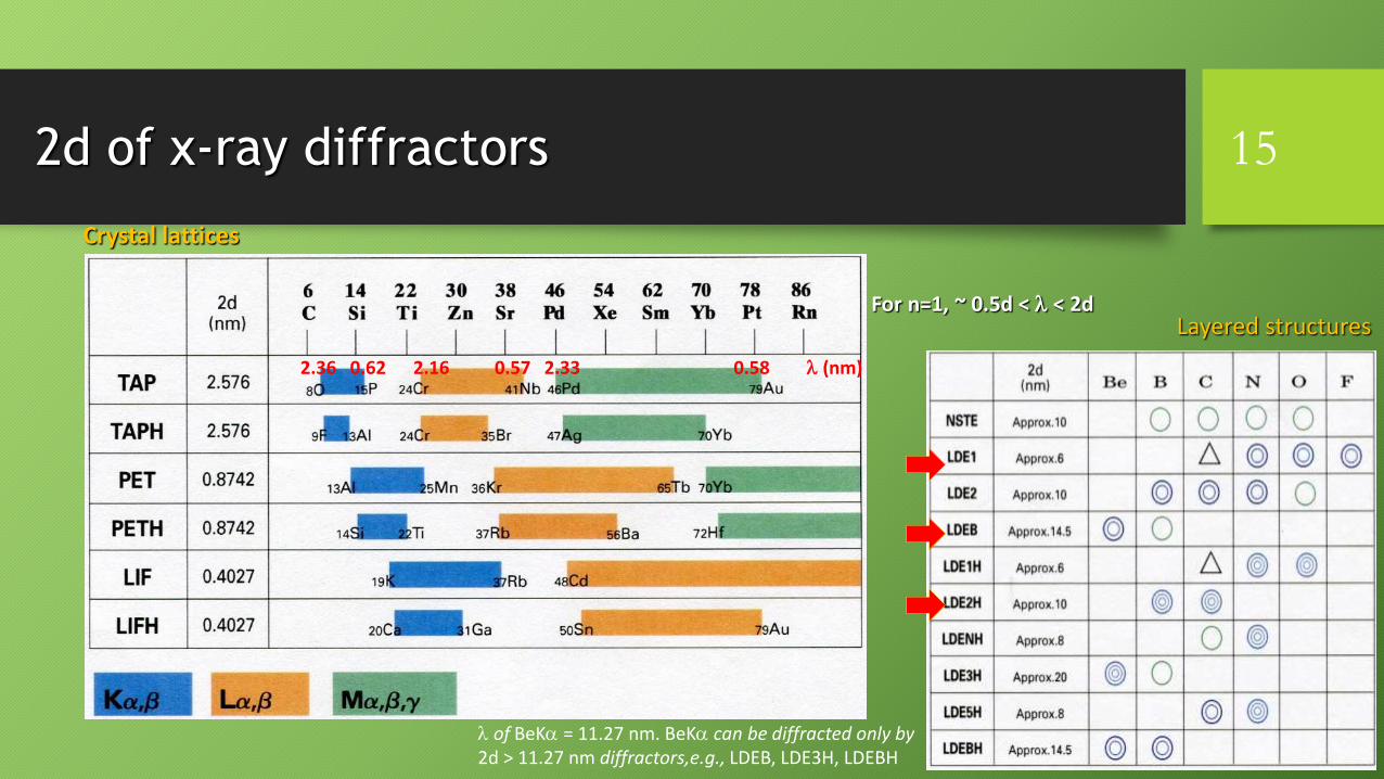
2d of x-ray diffractors
For n=1, ~ 0.5d < l < 2d
2.36 0.62 2.16 0.57 2.33 0.58 l (nm)
15
Crystal lattices
Layered structures
l of BeKa = 11.27 nm. BeKa can be diffracted only by2d > 11.27 nm diffractors,e.g., LDEB, LDE3H, LDEBH

WDS operation: detecting a specific l 16
Different wavelengths (l1, l2) can be diffracted by changing the L-value (L1, L2)
that effectively changes the incidence angle (q1, q2)
Radius of
focusing circle
(R) is fixed
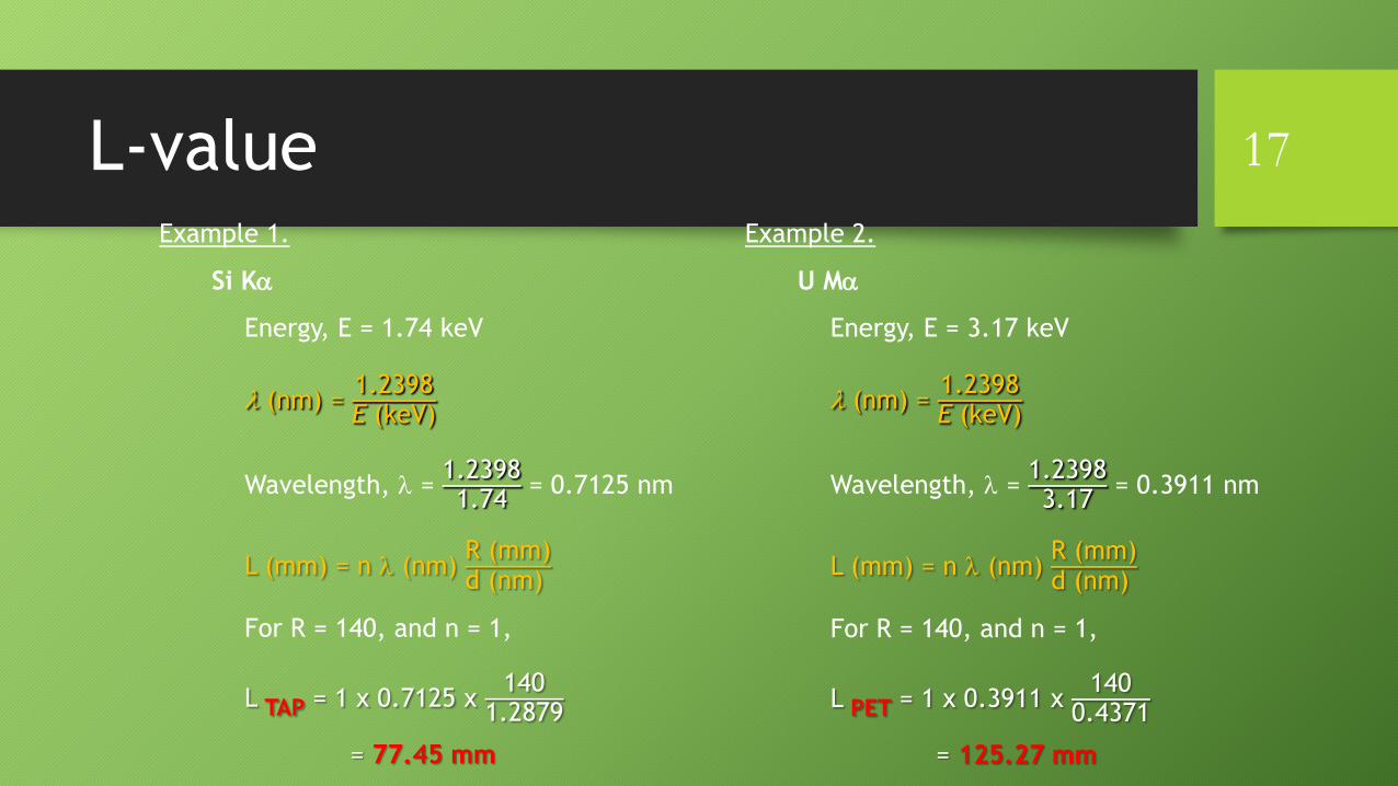
L-value 17
Example 1.
Si Ka
Energy, E = 1.74 keV
l (nm) = 1.2398E (keV)
Wavelength, l = 1.23981.74
= 0.7125 nm
L (mm) = n l (nm) R (mm)d (nm)
For R = 140, and n = 1,
L TAP = 1 x 0.7125 x 140
1.2879
= 77.45 mm
Example 2.
U Ma
Energy, E = 3.17 keV
l (nm) = 1.2398E (keV)
Wavelength, l = 1.23983.17
= 0.3911 nm
L (mm) = n l (nm) R (mm)d (nm)
For R = 140, and n = 1,
L PET = 1 x 0.3911 x 140
0.4371
= 125.27 mm

2R ≤ L ≤ 0
Theoretical and actual limits of spectrometer movement 18
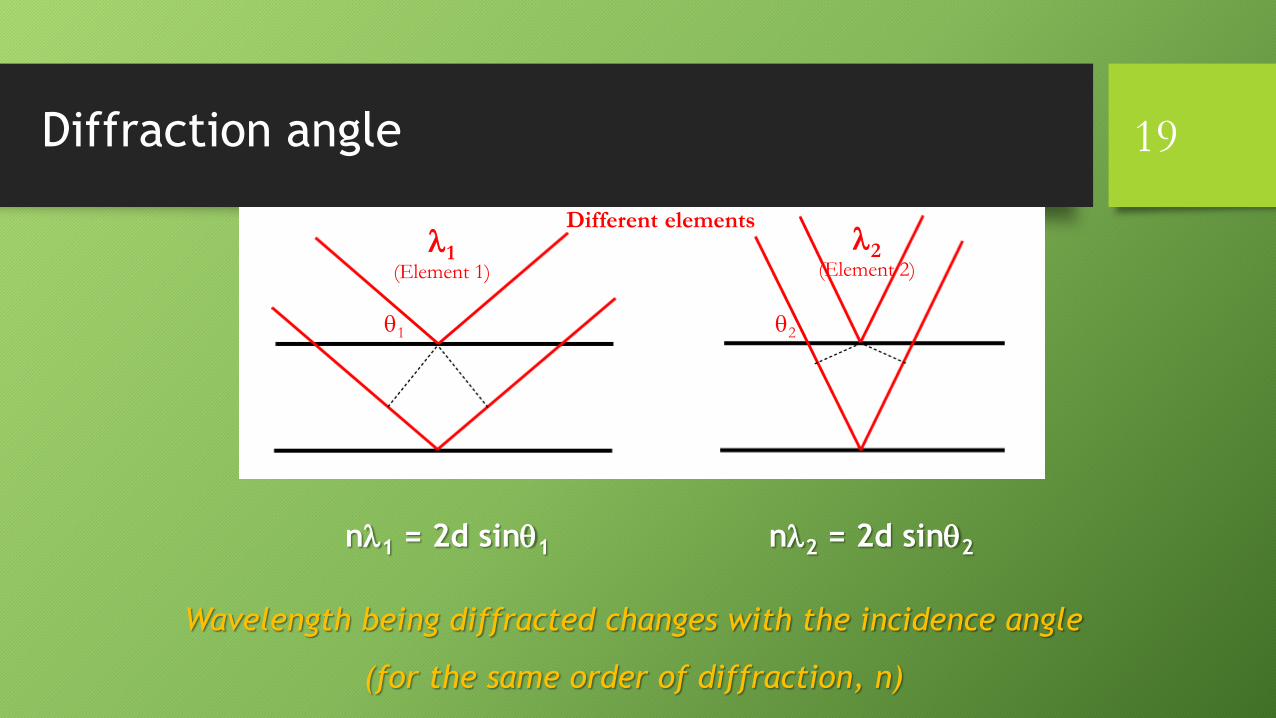
Diffraction angle
nl1 = 2d sinq1 nl2 = 2d sinq2
l1(Element 1)
q1 q2
l2(Element 2)
Wavelength being diffracted changes with the incidence angle
(for the same order of diffraction, n)
Different elements
19

First and second order diffractions
1l = 2d sinq1
= ABC
2l = 2d sinq2
=DEF
A
B
C
E
D F
n=1 n=2
q1 q2
path DEF = 2* path ABC
Same wavelength is being diffracted at different diffraction angles; sinq2 = 2sinq1
Same element
20

Spectral resolution 21
Full-Width Half-Maximum (FWHM)

Curved diffracting crystals
Johansson type
bending radius: 2R
polished and ground to R
Johan type
only bent to 2R,
not ground
R
22
Peak resolution with fully focusing Johansson-type crystal: FWHM ~10 eV
Some defocusing in Johan-type, but resolution is not compromised

WDS vs. EDS spectral resolution
Peak resolution with WDS (FWHM ~10 eV) is an order of magnitude better than with EDS (FWHM ~150 eV)
Peak overlaps in EDS
spectrum
23

X-ray focusing ellipsoid 24

WDS detector: Proportional counter
• Flow counter:• P-10 gas (90% Argon + 10% methane quenching agent)
• Polypropylene window
• Sealed counter:• Xenon gas
• Beryllium window
Tungsten collection wire
at 1-3 kV voltage
25
Voltage of the pulse
generated in the
wire is proportional
to the applied
voltage in the wire

Signal amplification
Typical voltage range in the proportional
counter region for a W wire: 1600-1850 V
26
(Voltage)
(fo
r p
uls
e vo
ltag
e)Signal is amplified in
the proportional
counter region
because of secondary
ionizations in the gas

Argon: long wavelength
(low energy) detection
Xenon: short wavelength
(high energy) detection
Lighter
elementsHeavier
elements
Counter gas efficiency 27
ArK absorption edge is at Ec(Ar K-shell)
XeL absorption edge is at Ec(Xe L-shell)
(Ec: critical excitation energy)
X-ray entering detector (EX-ray)
ionizes the Ar K-shell or Xe L-shell
when overvoltage
U = EX−ray
Ec(Ar K−shell or Xe L−shell)> 1
and fluoresces ArKa or XeLa

Proportional counter setup 28dE
baseline
window
A Single Channel
Analyzer (SCA)
allows only pulses
from x-rays to pass
through the energy
window DE
SCA scan shows the variation in count rate as a small
voltage window (dE) is moved across the voltage range
Proportional
counter output:
Voltage pulses
from noise and
x-ray signal
Baseline and window voltages (DE) are set to filter out noise
DE is determined through Pulse Height Analysis (PHA)

Pulse voltage in SCA scan 29
SCA scan
Energy of SiKa (1.739 keV)
is ~1.4 times the energy of
MgKa: (1.253 keV)
If the pulse for MgKa is at 4 V,
the pulse for SiKa will be at 4 x 1.4 = ~5.6 V

Escape peak in SCA scan 30
SCA scan
Escape peaks:
• P-10 counter: ArKa
• Xenon counter: XeLa
Energy difference
between the x-ray
of interest and
ArKa or XeLa

Proportional counter window
• Mylar has lower transmittance than polypropylene, especially for light element x-rays
• Thin windows are better for light elements
1 mm thick polypropylene window transmits ~60% of the F Ka
6 mm thick polypropylene window transmits only ~5% of the F Ka
31

Detector slit
• Positioned at focal point of diffracted x-rays on the Rowland circle
• Cuts off stray x-rays and electrons
32
Open: LDE P-10 flow counter Very light elements
(very low E, very long l)
550-300 mm: PET or LIF Xe sealed counter Heavy elements
(high E, short l)
300 mm: TAP P-10 flow counter Light elements
(low E, long l)
300 mm PET or LIF P-10 flow counter Heavy elements
with Mylar film: (high E, short l)

Semi-quantitative analysis33

Compositional imaging with x-rays: elemental mapping
• Beam-rastered image:
electron beam rasters over the area to be imaged
• Stage-rastered image:
electron beam is stationary, stage moves
34

Background in x-ray spectra
Characteristic X-rays
Bremmstrahlung
(continuum) X-rays
Ti Ka
Fe Ka
Ti KbFe Kb
Peak intensity
Background intensity
Peak minus Background
Wavelength
Energy
Intensity
35
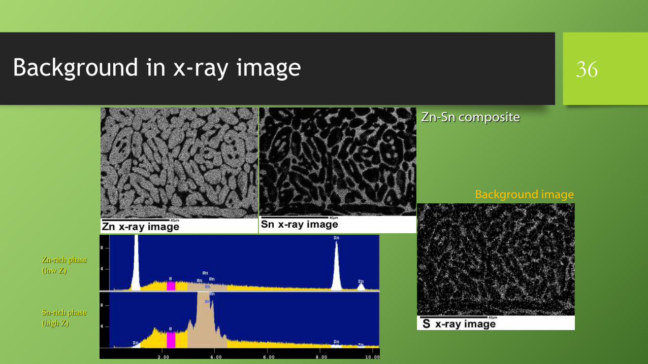
Zn-Sn composite
Background in x-ray image
Background image
36
Zn-rich phase
(low Z)
Sn-rich phase
(high Z)

X-ray defocusing in beam-rastered image 37

Image quality of x-ray maps
Two factors:
Image resolution:
number of points measured within the imaged area
X-ray Signal:
beam current and counting (dwell) time per point
38

Combined WDS and EDS X-ray mapping 39

Combined BSE, CL and X-ray mapping40