Embed Size (px)
DESCRIPTION
Understanding the Mechanical seals as a flexible elimination of liquid barrier systems without any need of springs, this is ideal for high pressure and high temperature applications with their durable nature.
Citation preview
UNDERSTANDING
MECHANICAL SEALS

INTRODUCTION
• Since their inception, mechanical seals have carried with them amystique of “Gee Whiz”, bizarre, physics defying properties that havebaffled the untrained observer. But that impression is really misplaced.Mechanical seals are not magic by any means and actually performwell within the realm of easy to understand principles of physics andhydraulics.
• Mechanical seals are simply another means of controlling leakage of aprocess where other means are deemed to be less capable ofperforming the task adequately. For the purposes of this discussion,consider that a mechanical seal will out-perform common types ofpacking.
• As mechanical seals can be used to seal a myriad of different productson an equally vast array of equipment, we will be primarily focusing onthe use of mechanical seals on rotating shaft pumps. Since our subjectis dealing with pumps, let’s first explore a basic understanding of theneed to seal a process liquid in a centrifugal pump.
CENTRIFUGAL PUMPS
A centrifugal pump is simply a shaft, suspended on bearings
with an impeller attached to one end. The impeller is
encased in a housing that is filled with a liquid. As the shaft
is rotated, centrifugal force expels the liquid out through an
orifice, where it is typically piped into a process or another
collection point. As the expelled liquid exits the case,
additional liquid is added to the case so that a flow
develops. That is basically how a centrifugal pump works.
The next slide shows a photograph of a typical “End Suction
Centrifugal Pump”.

PUMP SHAFT
BEARINGSIMPELLER

AS THE PUMP SHAFT ROTATES
A LIQUID IS SUPPLIED TO THE
PUMP “SUCTION”
CENTRIFUGAL FORCE EXPELS THE
LIQUID OUT FROM THE IMPELLER
CENTRIFUGAL PUMPS
The force of the expelled liquid creates pressure.
This liquid under pressure will seek areas of lower
pressure. This is a known physical principle of
hydraulics. Some form of seal must be applied to
keep liquid from leaking around the shaft at the
point where it enters the case to drive the impeller.
This is where our mechanical seal comes into play.
Take a look at the same pump again. Can you see
the mechanical seal behind the impeller?

SEAL TYPE
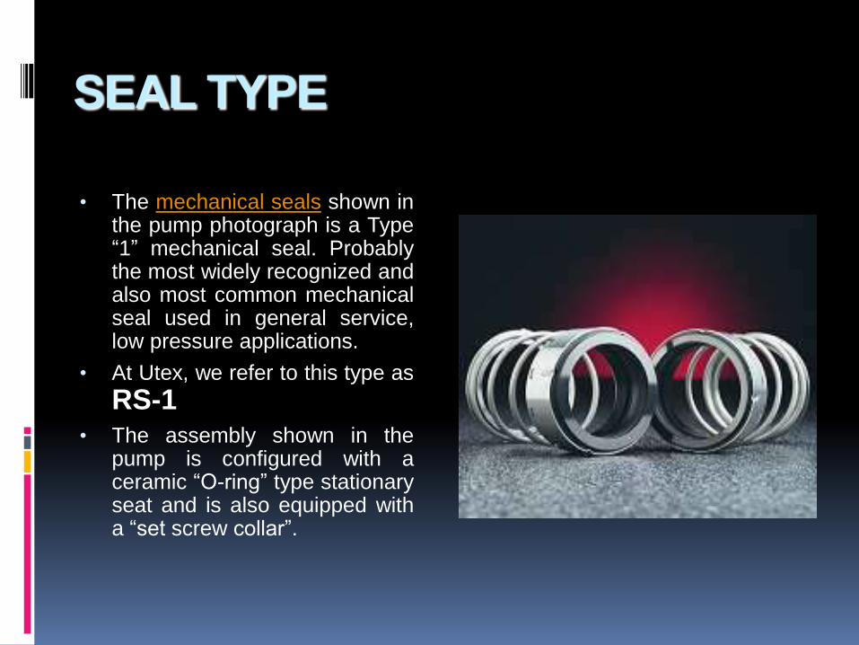
• The mechanical seals shown inthe pump photograph is a Type“1” mechanical seal. Probablythe most widely recognized andalso most common mechanicalseal used in general service,low pressure applications.
• At Utex, we refer to this type as
RS-1• The assembly shown in the
pump is configured with aceramic “O-ring” type stationaryseat and is also equipped witha “set screw collar”.

SEALING THE LIQUID
Mechanical seals were originally designed to lend a greater
sealing capability than could be achieved using common
packing.
Before the advent of mechanical seals, pump users relied
primarily on “rope” or braided style packing to achieve a
“seal” around the shaft. A series of pieces or “rings” were
installed into the pump “stuffing box” and they were
compressed tightly so that they created a difficult leak path for
the liquid to negotiate in order to leak to atmosphere.

SEALING THE LIQUID
Early packing styles did not seal very well. In fact, until
recently, braided packing styles required varying amounts
of leakage for lubrication. If leakage was not permitted to
occur, the packing would literally “burn up” and often cause
severe damage to the pump shaft. Even with adequate
leakage for lubrication, pump shaft wear was a commonly
expected occurrence and as the shaft wore it would in turn,
cause poor shaft packing life.
As leakage becomes more excessive, the gland is
tightened to reduce leakage.


SEALING THE LIQUID
With the introduction of mechanical seals, this leakage
could be controlled to a much greater degree.
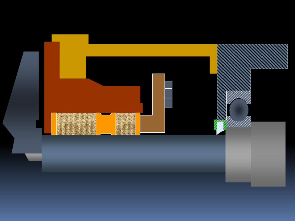
Let’s look at the same pump with a mechanical seal
installed. Note that the seal shown is an RS-1 with O-Ring
type stationary and a set screw collar.


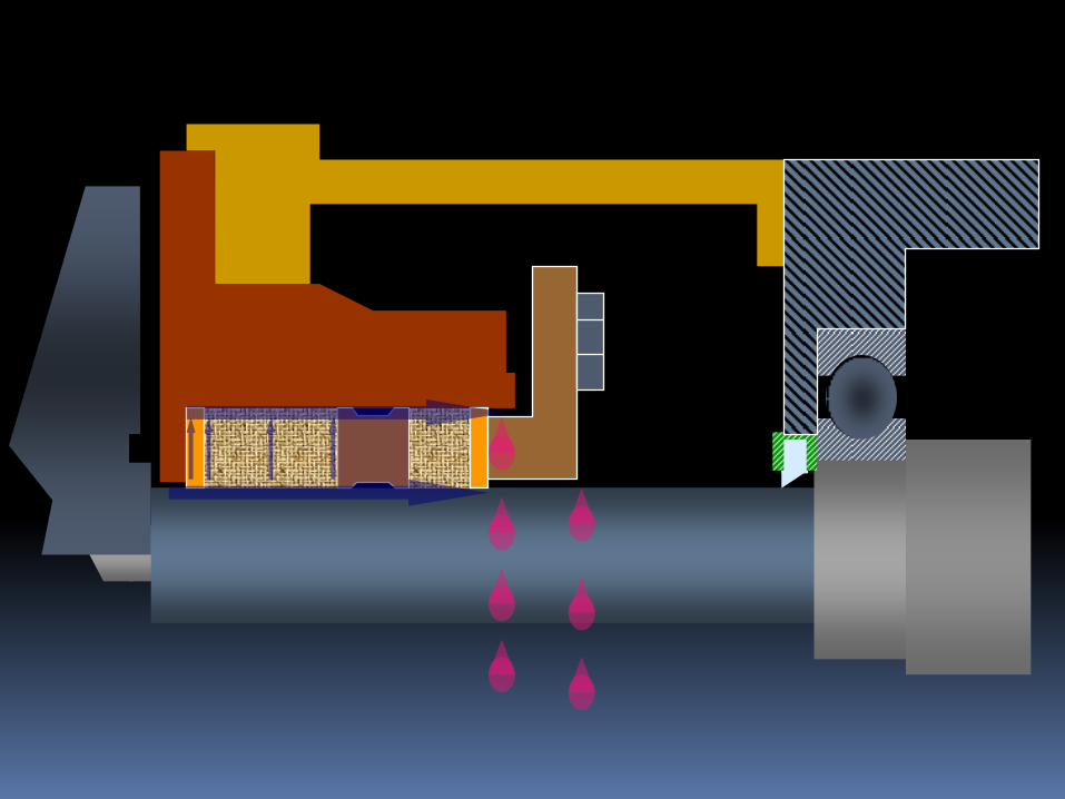
SEALING THE LIQUID
You have probably taken notice of the illustration
showing minor leakage to atmosphere. It is appropriate
to point out at this time…

LESSON NUMBER ONE
ALL
MECHANICAL SEALS
LEAK.

SEALING THE LIQUID
It is a fact, all mechanical seals leak. Like packing, the
mechanical seal “faces” must also be lubricated. With proper
application and design however, the leakage is so minute that
actual droplets of liquid are not detected. Instead, the
lubricating liquid will vaporize as it crosses the seal faces and
the leakage is a gas or vapor.
Since we are discussing the sealing of the liquid at the faces,
let’s take a look at the sealing points of a typical mechanical
seal. Again, viewing the same pump and seal, note that there
are four sealing points to consider.

Sealing on the shaftO.D. of the stationary
The seal gland to the
stuffing box
And finally, the seal faces
BRIEF DISCUSSION
ABOUT MECHANICAL
SEAL FACE DYNAMICS
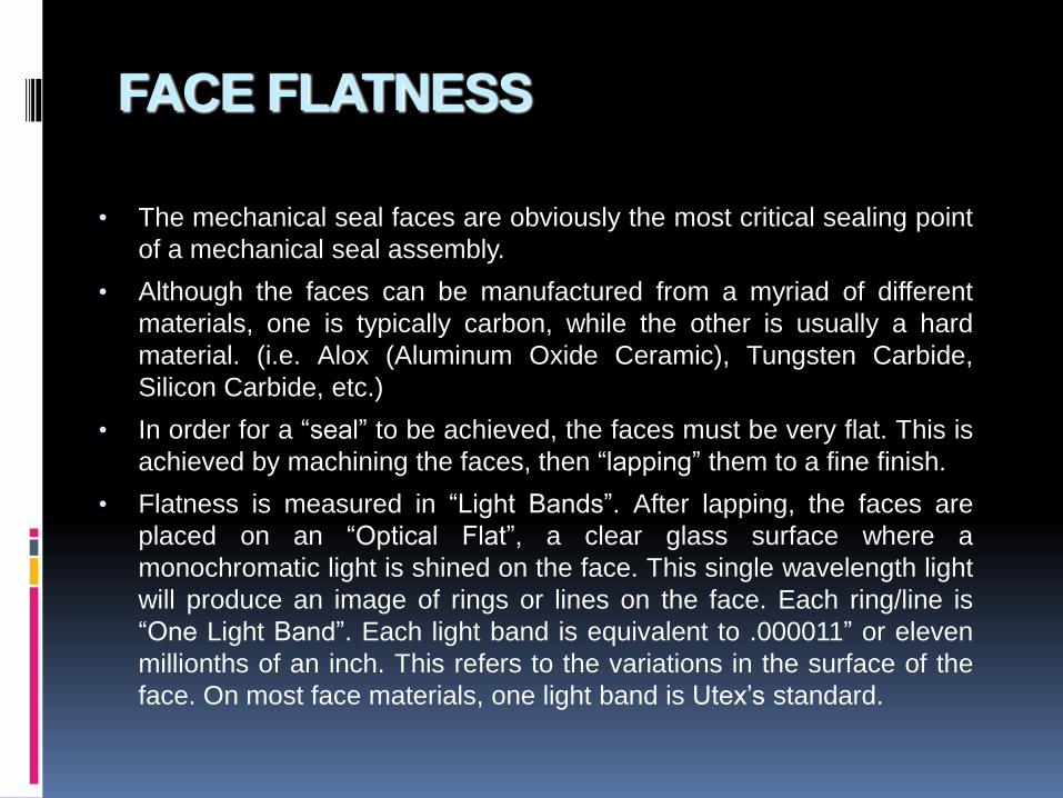
FACE FLATNESS
• The mechanical seal faces are obviously the most critical sealing point
of a mechanical seal assembly.
• Although the faces can be manufactured from a myriad of different
materials, one is typically carbon, while the other is usually a hard
material. (i.e. Alox (Aluminum Oxide Ceramic), Tungsten Carbide,
Silicon Carbide, etc.)
• In order for a “seal” to be achieved, the faces must be very flat. This is
achieved by machining the faces, then “lapping” them to a fine finish.
• Flatness is measured in “Light Bands”. After lapping, the faces are
placed on an “Optical Flat”, a clear glass surface where a
monochromatic light is shined on the face. This single wavelength light
will produce an image of rings or lines on the face. Each ring/line is
“One Light Band”. Each light band is equivalent to .000011” or eleven
millionths of an inch. This refers to the variations in the surface of the
face. On most face materials, one light band is Utex’s standard.
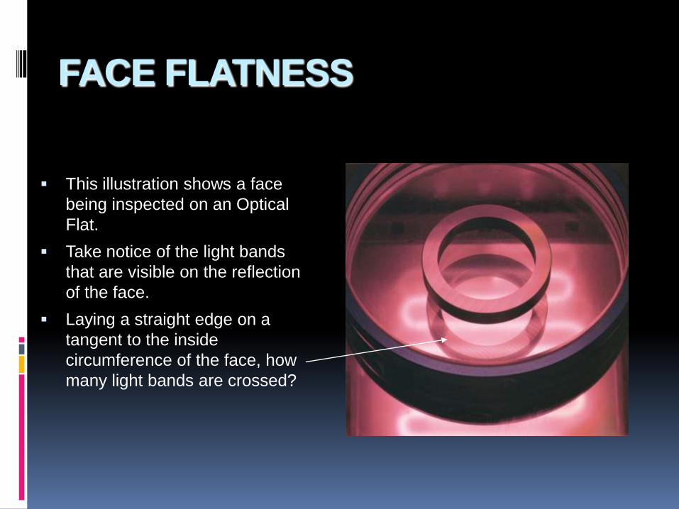
FACE FLATNESS
This illustration shows a face
being inspected on an Optical
Flat.
Take notice of the light bands
that are visible on the reflection
of the face.
Laying a straight edge on a
tangent to the inside
circumference of the face, how
many light bands are crossed?

Optically Flat Faces
0 psi
Rotary
FaceStationary
Face
100 psi

FACE FLATNESS
As was stated earlier, it is hoped that the application and design
of the mechanical seal is suited for the service. If so, there is
leakage of only vapor through the seal faces.

0 psi
25 psi
50 psi
Liquid
Liquid + Vapor
Vapor + Liquid
Vapor
Pressure Drop & Vaporization
100 psi

TYPES OF
MECHANICAL SEALS

SEAL TYPES
There are obviously many different types and
configurations of mechanical seals. Shaft mounted and
cartridge, balanced and unbalanced, pusher and non-
pusher, single and multiple, etc., etc.
Here we will examine the basic differences without going
into a great detail.

SEAL TYPES
First, let us examine shaft mounted vs. cartridge.
A shaft mounted seal requires the pump user or assembler
to actually install individual seal components into the
equipment.
Let’s look at the installation of the RS-1 that we were
looking at previously.
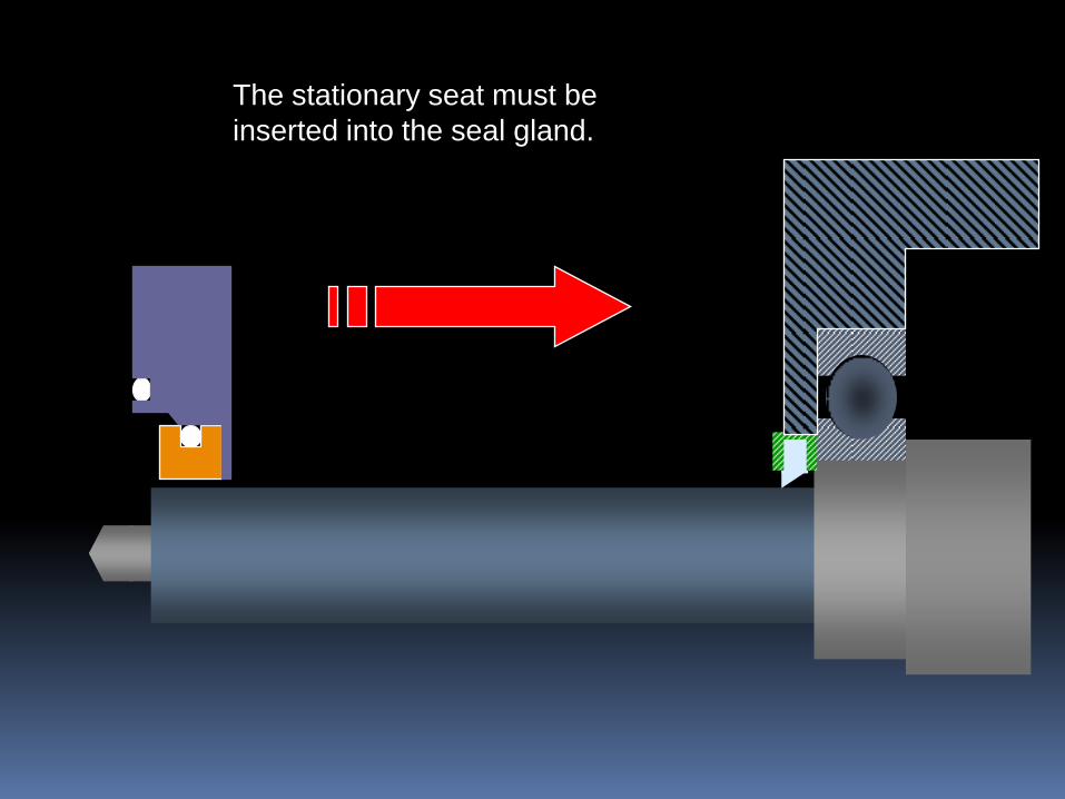
The stationary seat must be
inserted into the seal gland.
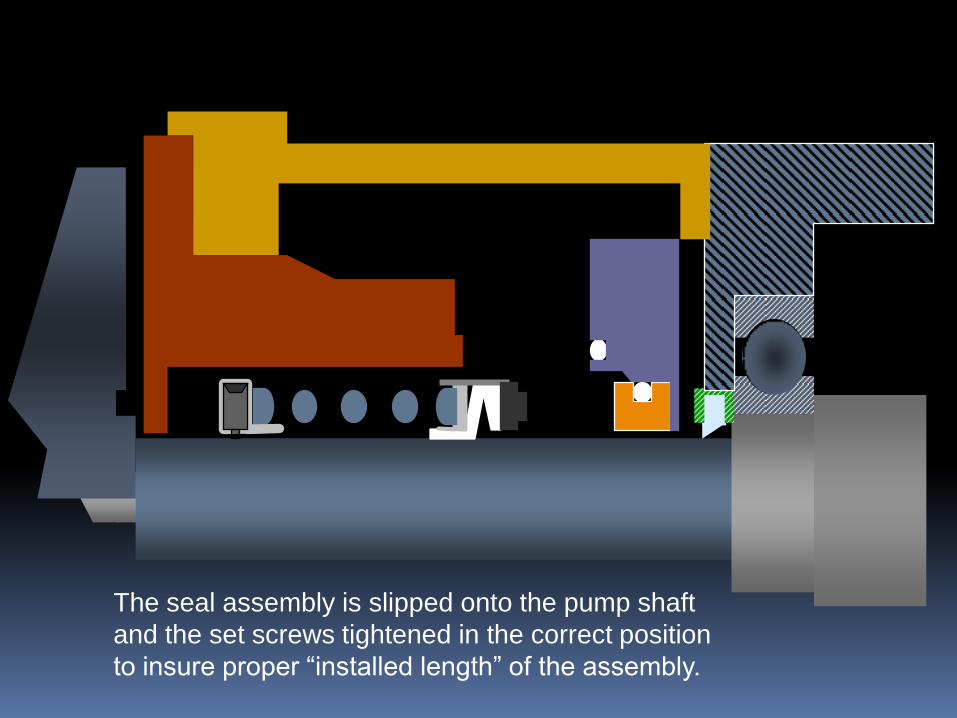
The seal assembly is slipped onto the pump shaft
and the set screws tightened in the correct position
to insure proper “installed length” of the assembly.
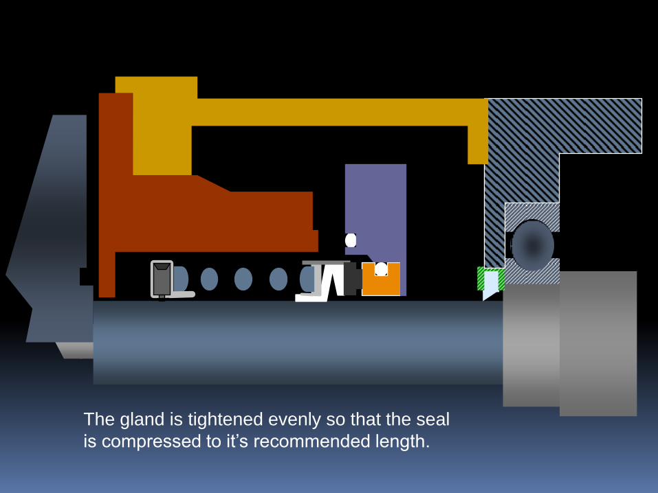
The gland is tightened evenly so that the seal
is compressed to it’s recommended length.


SEAL TYPES
A cartridge type mechanical seal is a pre-assembled
package of seal components making installation much
easier with fewer points for potential installation errors to
occur.
The assembly is “pre-set” so that no installed length
calculations must be performed for determining where to
set the seal. This pre-set is achieved by the use of “set
tabs” that are removed once the seal is installed and the
pump assembled.
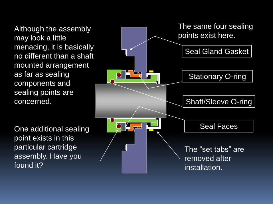
Although the assembly
may look a little
menacing, it is basically
no different than a shaft
mounted arrangement
as far as sealing
components and
sealing points are
concerned.
The same four sealing
points exist here.
Stationary O-ring
Seal Gland Gasket
Shaft/Sleeve O-ring
Seal Faces
The “set tabs” are
removed after
installation.
One additional sealing
point exists in this
particular cartridge
assembly. Have you
found it?
SEAL TYPES
Remember the number of steps involved in installing the
shaft mounted seal.
Now let’s look at installing the cartridge seal that we just
examined.


PUSHER VS. NON-PUSHER
Both pusher and non-pusher types can be either shaft
mounted or cartridge assemblies.
The basic difference between pusher and non-pusher types
have to do with the dynamics of the shaft packing or O-ring
and whether or not it moves as the seal wears.
As the seal faces wear down over time, they must be
closed to compensate for lost face material. If the shaft O-
ring must move when this compensation takes place, it is
pushed forward by the components of the seal and by
stuffing box pressure. If the seal is configured with a
“dynamic” O-ring of this type the seal is called a pusher
type.

Illustrated here is a Type RS-81, a common pusher seal. As the seal
springs and other pressures in the stuffing box are exerted on the seal,
closure of the faces is achieved.
Rotating face and
dynamic O-ring.
Hard Stationary Face
Closing forces exerted
on the seal faces

As the softer carbon face wears down, the rotating face must
move to maintain face closure.

Minute particles of carbon and solids from the process liquid
that migrate across the seal faces build up on the shaft.

This build up will ultimately cause the seal to “hang up” and in most
cases, failure will occur well before the seal is actually “worn out”.


PUSHER VS. NON-PUSHER
There are seal types that have no dynamic O-rings. All
O-rings are “static” and the seal components
compensate for face wear without “pushing” any sealing
points.
One of these types is called a “Metal Bellows Seal”. The
bellows can be constructed of metal, rubber or PTFE.
The RS-1 seen earlier in this presentation is an
“Elastomer (or Rubber) Bellows Seal”.
Let’s consider the metal variety.

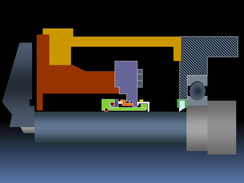
METAL BELLOWS
Metal bellows are constructed
by welding “leaflets” into a
series of “convolutions”. This
series of convolutions is
referred to as the “Bellows
Core”.
The photo shown here is a
shaft mounted “Utex-MB”.
Now take a look at how a
bellows seal compensates for
face wear.

Metal bellows
Carbon rotating face
Hard stationary face


The bellows core expands to
compensate for face wear.
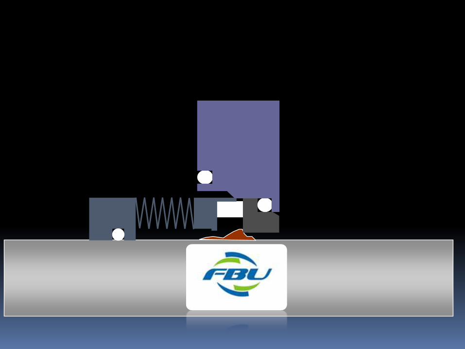
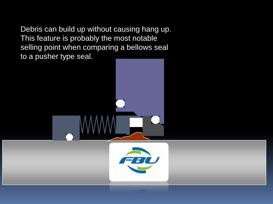
Debris can build up without causing hang up.
This feature is probably the most notable
selling point when comparing a bellows seal
to a pusher type seal.

BALANCED VS. NON-BALANCED
When speaking of “Balance” in reference to mechanical
seals, we are not talking about Mechanical or Rotational
Balance. Instead, we are referring to Hydraulic Balance.
Since mechanical seals are subject to stuffing box pressure,
this pressure is utilized to achieve and maintain seal face
closure in a non-balanced seal.
If stuffing box pressure is very high, typically over 100psi.,
then the closing force may be too great to allow the
“Boundary Layer Liquid” that lubricates the faces to be
sufficient and the faces will wear prematurely.
A balanced seal compensates for higher pressures by
locating the seal faces such that stuffing box pressure has
less effect on face closure.

A non-balanced seal has faces located
outside the “Balance Diameter” of the
seal. Stuffing box pressure is applied
to the faces virtually evenly.
Bala
nce
Lin
e
Face
ID
Lin
e
Face
OD
Lin
e
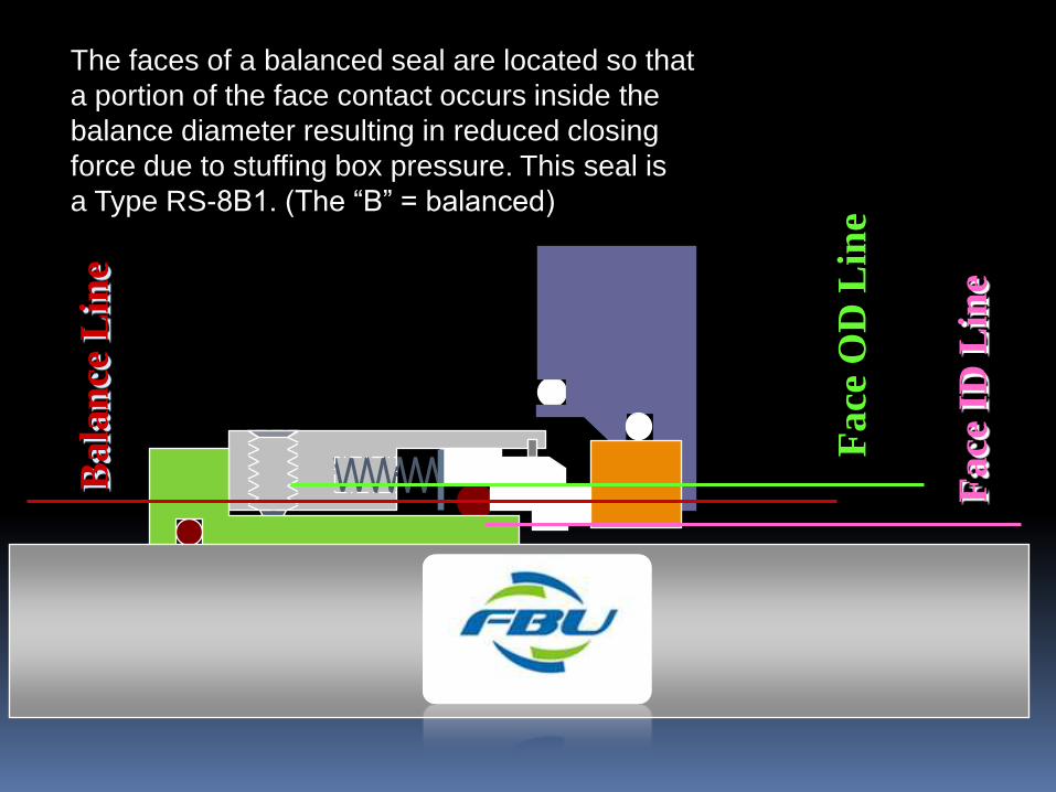
The faces of a balanced seal are located so that
a portion of the face contact occurs inside the
balance diameter resulting in reduced closing
force due to stuffing box pressure. This seal is
a Type RS-8B1. (The “B” = balanced)
Bala
nce
Lin
e
Face
ID
Lin
e
Face
OD
Lin
e

Most metal bellows seals are balanced.
Fa
ce O
D L
ine
Face
ID
Lin
e
Ba
lan
ce L
ine

SINGLE VS. MULTIPLE
Most rotating equipment is equipped with a single seal.
This is what we have been examining thus far. Single
shaft mounted seals, cartridges seals, balanced seals
etc.
Some applications call for a multiple seal configuration.
These are typically dual seal arrangements but can also
be a series of three or more. For our purposes we will
examine dual seal arrangements since that really covers
99% of multiple seal applications.

DUAL SEALS
Dual seals can be either pressurized or non-pressurized. This is in
reference to the artificial environment that is provided to exist
“between” the seals.
A non-pressurized dual seal, also known as a “Tandem” arrangement,
means that the inner, or primary seal is functioning as would a single
seal. It is subject to stuffing box conditions, i.e. stuffing box pressure,
process liquid to lubricate the faces and usually immersion of seal
components in the process liquid. The secondary, or outside seal runs
in a non-pressurized “Buffer” liquid that is supplied from an outside
source, typically a nearby supply tank.
In a non-pressurized dual arrangement, the outside seal is primarily
there as a containment device in the event that the inside or primary
seal is lost. A “Back up” or safety mechanism if you will.
Let’s look at a Dual Cartridge Seals.

Inside or Primary seal
Outside or Secondary Seal
Immersed in process liquid
in the stuffing box
Buffer fluid warmed
by seal generated
heat returns to the
buffer supply tank
Cool buffer fluid
from the buffer
supply tank enters
via the inlet port

DUAL SEALS
Since the outside or secondary seal runs in a non-pressurized
clean lubricating liquid, it will generally last for an extended
period of time. When the inside or primary seal fails, the
leakage through the faces will be contained by the secondary
seal until the pump can be shut down for seal replacement.
Failure indication and shutdown devices can be attached to
the buffer supply so that the pump operators know when the
primary seal has failed.
DUAL SEALS
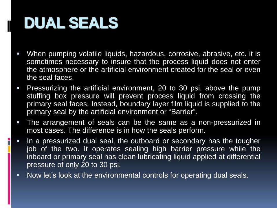
When pumping volatile liquids, hazardous, corrosive, abrasive, etc. it issometimes necessary to insure that the process liquid does not enterthe atmosphere or the artificial environment created for the seal or eventhe seal faces.
Pressurizing the artificial environment, 20 to 30 psi. above the pumpstuffing box pressure will prevent process liquid from crossing theprimary seal faces. Instead, boundary layer film liquid is supplied to theprimary seal by the artificial environment or “Barrier”.
The arrangement of seals can be the same as a non-pressurized inmost cases. The difference is in how the seals perform.
In a pressurized dual seal, the outboard or secondary has the tougherjob of the two. It operates sealing high barrier pressure while theinboard or primary seal has clean lubricating liquid applied at differentialpressure of only 20 to 30 psi.
Now let’s look at the environmental controls for operating dual seals.
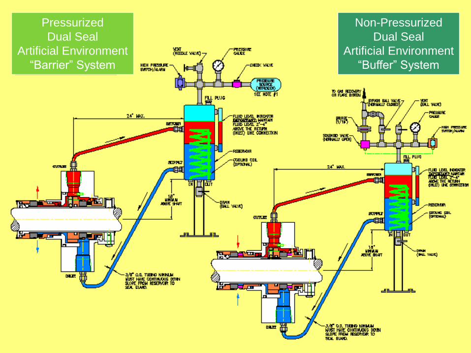
Pressurized
Dual Seal
Artificial Environment
“Barrier” System
Non-Pressurized
Dual Seal
Artificial Environment
“Buffer” System

TO FLARE /
RECOVERY SYSTEM
DISCHARGE
SU
CT
ION
NON-PRESSURIZED
BUFFER FLUID
PLAN 52 / 7352

PRESSURIZED BARRIER FLUID
PLAN 53 / 7353
PRESSURIZED GAS IN
DISCHARGE
SUCTION

DUAL SEALS
There are many more types of environmental control
arrangements that are discussed in other programs. This
presentation simply covers the basics. For more detailed
information on this topic, contact your supervisor or a Sealing
Technologies Representative.
SPLIT SEALS
Some types of machinery are cumbersome to maintain. Largeshafts, heavy components, and immovable drivers are some ofthese concerns.
Often, a typical mechanical seal is impractical to use by thenature of it’s installation requirements.
In these cases it is frequently beneficial to use a Split Seal.
In a Split Seal, all components are literally cut or split in half andthey are assembled onto the equipment without removal ordisassembly of the major equipment components.
Obviously, these seals are prone to leak more readily than non-split seals so they are generally applied to processes wheresome leakage is acceptable. Even with some leakage, they willout perform common packing.
Split Seals are often used on mixers, agitators and large volume,large shafted pump seals.
UTEX EZ-SEAL
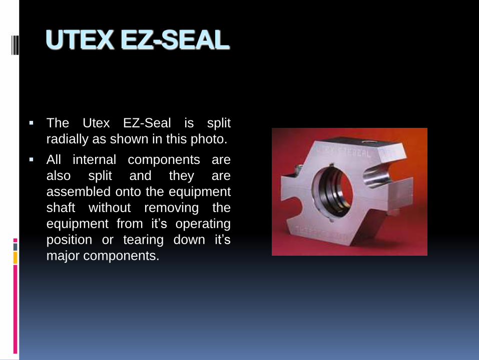
The Utex EZ-Seal is split
radially as shown in this photo.
All internal components are
also split and they are
assembled onto the equipment
shaft without removing the
equipment from it’s operating
position or tearing down it’s
major components.

UTEX EZ-SEAL

SPLIT SEALS
Aside from the fact that the components are split, split seals
operate virtually the same way that most single cartridge or shaft
mounted seals operate.
By nature of their split design, their application is limited to lower
pressures and non-volatile liquids.
Now let’s move onto our final discussion topic, Gas Buffer Seals.
GAS BUFFER SEALS
The final seal type that we will look at during this course is the
Gas Buffer Seal.
Gas Buffer Seals are the latest advancement in sealing
technology. There are as many different types as there are
Sealing Product Manufacturers.
They were designed to facilitate capabilities similar to a dual
seal without requiring elaborate environmental controls or in
the case of pressurized dual seals, without liquid
contamination of the process liquid.
We will briefly discuss the features of the Utex DCG Seal.
DUAL CO-AXIAL GAS SEAL
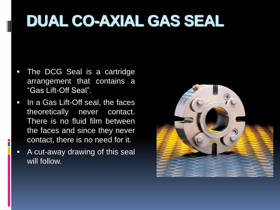
The DCG Seal is a cartridge
arrangement that contains a
“Gas Lift-Off Seal”.
In a Gas Lift-Off seal, the faces
theoretically never contact.
There is no fluid film between
the faces and since they never
contact, there is no need for it.
A cut-away drawing of this seal
will follow.

DUAL CO-AXIAL GAS SEAL
This control panel is used to
adjust the gas flow (Nitrogen,
Clean Plant Air, CO2, etc.) that
is inject into the seal gland port
at 25 to 30 psi. over stuffing box
pressure. The gas flows through
holes in the carbon stationary,
separating the faces.
As the seal operates, an
envelope of gas surrounds the
seal faces keeping process
liquid out.

UTEX DUAL CO-AXIAL GAS SEAL
Cut away view of the
DCG shows the Stationary
Carbon Face
Rotating Face Gas inlet
port
Thumb not an integral
part of the seal assembly

UTEX DUAL CO-AXIAL GAS SEAL
The equipment
can then be started
and process suction
opened allowing
liquid into the
stuffing box.
Gas is supplied
to the inlet port.

GAS BUFFER SEALS
More detailed discussion of Gas Seals and their
application is available.

PROGRAM SUMMARY
Through this program we have looked at the basic principles
and designs of mechanical seals.
It is important to understand that detailed explanation of each
topic discussed here is available.
Hopefully this presentation has helped to improve your
understanding of mechanical seals.
Review this program again and as you have questions,
comments or suggestions, ask your supervisor or a Sealing
Technologies Representative. We want this training program
to be as effective as possible and your input is valuable.
Thanks, and enjoy working with mechanical seals.

UNDERSTANDING
MECHANICAL SEALS
PROGRAM END