Embed Size (px)
Citation preview

Understanding STP and RSTP Convergence INE, Inc
Copyright © INE www.INE.com 1
Understanding STP and RSTP Convergence
Introduction ...................................................................................................... 2 Classic STP Convergence ............................................................................... 3
Spanning Tree Algorithm Features ............................................................ 3 Handling Direct Link Failures ..................................................................... 4 Handling Indirect Link Failures ................................................................... 5
Signaling Topology Changes in STP ............................................................... 7 STP Convergence Improvements ................................................................... 8
STP Timers Tuning .................................................................................... 8 STP Extensions: UplinkFast & FlexLinks ................................................... 9 STP Extensions: BackboneFast ............................................................... 11
STP Summary ............................................................................................... 14 RSTP Sync Process ...................................................................................... 15
RSTP’s BackboneFast Equivalent ........................................................... 17 RSTP Topology Changes .............................................................................. 18
Process Overview .................................................................................... 18 Optimizations ............................................................................................ 19
RSTP Illustrated using Ring Topology ........................................................... 20 Failure 1: Link Failure ............................................................................... 21 Failure 2: Non-Root Bridge Failure .......................................................... 23 Failure 3: Root Bridge Failure .................................................................. 25
RSTP Counting to Infinity .............................................................................. 28 RSTP Conclusions......................................................................................... 33 Self-Assessment ............................................................................................ 33 Further Reading ............................................................................................. 34

Understanding STP and RSTP Convergence INE, Inc
Copyright © INE www.INE.com 2
Introduction This blog post is dedicated to discussing at length the finer details of the Spanning Tree Protocol (STP) and its much more recent update, the Rapid Spanning Tree Protocol (RSTP). Although both have been in use for quite some time, people tend to gloss over some fundamental details concerning STP and RSTP. Furthermore, RSTP is quite possibly one of the most poorly understood protocols in wide use today, as its most frequent feature quoted by many is “it converges in less than one second”. This blog post aims to shed light on the principles behind STP and RSTP and give the audience an improved knowledge of each protocols behavior in a networked environment when attempting to obtain a target convergence time for both protocols. In addition to this, some design considerations are also revealed and explained in relation to RSTP and its variants that are currently used today. The expected knowledge level of readers of this document is assumed to have a basic, underlying understanding of both STP and RSTP protocols.

Understanding STP and RSTP Convergence INE, Inc
Copyright © INE www.INE.com 3
Classic STP Convergence Spanning Tree Algorithm Features Before we begin with the newer RSTP, let’s recap classic Spanning Tree Algorithm (STA) convergence properties. STA follows particular procedure to calculate the loop-free subset of redundant network topology. STA implements distributed variation of the Bellman-Ford iterative algorithm, which could be described as a “gradient” process, meaning it repeatedly looks for the optimal solution, selecting an “optimal” candidate every time. Every bridge (with except to the root) accepts and retains only the best current root bridge information, electing one root port upstream toward the root bridge. Bridges then block alternate paths to the root bridge, leaving only the single optimal upstream path and continue relaying optimal information downstream. If bridge learns of a better (“superior”) root bridge, on any of its ports, the previous “best” information is erased and the new one immediately accepted and relayed. Switches store the most recent STP BPDUs (Bridge Protocol Data Units) with every port that receives them, even blocked ports. Only the best information is relayed downstream. There are two important stability properties incorporated in STA:
o Topology synchronization timeout. Any change in the information
associated with a port that unblocks the port, forces the port go through the sequence of Listening and Learning States. This process takes exactly 2xForward_Time seconds. The reason for this delay is ensuring that new information is disseminated among other bridges and MAC addresses are re-learned.
o Aging out old information. Every configuration BPDU contains two fields: Max_Age and Message_Age. The Message_Age field is incremented every time a BPDU traverses a bridge. When a bridge stores the BPDU with the respective port, it will count the time in seconds, starting from Message_Age up to the Max_Age. If during this interval, no further BPDUs are received, the current BPDU information is expired and the port is declared designated. This procedure ensures that the old root information is eventually aged out of the topology.
The gradient nature of STA determines the way it handles inferior BPDU information. When a BPDU is considered inferior, or if it carries information about the root bridge that is worse than the one currently stored for the port, i.e. has a less preferred priority vector. Inferior BPDUs may appear when a neighboring bridge loses its root port having no alternate path and claims itself the new root for the topology.

Understanding STP and RSTP Convergence INE, Inc
Copyright © INE www.INE.com 4
Bridges ignores inferior BPDUs until old BPDU information expires in (Max_Age – Message_Age) seconds. The old information could be either one associated with blocked port or the root port. Ignoring inferior BPDUs allows for guaranteed recovery in situations when bridge receiving inferior BPDUs still has active path to the real root bridge. In cases when the root bridge goes down, however, this process makes convergence slower by adding extra overhead of almost Max_Age time. Handling Direct Link Failures Keeping the above information in mind, consider the scenario when a link directly connected to the bridge fails. Failure could be detected in one of two ways: by sensing signal loss at physical level or by missing BPDU information for Max_Age-Message_Age seconds, if physical layer cannot detect the failure. Depending on the port state, STA will handle failure event differently:
o If the port was blocking, nothing happens with except to expiring information associated with the failed port.
o If the port was designated, local bridge does nothing. However, downstream bridge may detect the loss of a root port and start re-converging.
o If the port was root port, information stored with the root port is invalidated and the bridge attempts to elect new root port based on stored information. If such port can be found, it is unblocked and transitioned through Listening/Learning states.
o If there are no more root ports left after the link failure, the bridge declares itself as root and starts announcing that in BPDUs. Downstream bridges will ignore this information until old information expires.
At best, the above convergence process would take only 2xForward_Time, typically demonstrated in cases when link failure is detected by the physical layer. If BPDU aging is used instead, it takes every bridge (Max_Age-Message_Age)+2xForward_Time to adapt to the new topology, with the maximum time being Max_Age+2xForward_Time. It is important to notice that changes of BPDU information on any of the blocked ports will cause similar convergence process. For example, if BPDU information is coming from the same root bridge, but other metrics change (e.g. a better root cost received on blocked port), the blocked port receiving the information is promoted to a root and the previous root is blocked. It takes 2xForward_Time to adapt to this change. However, inferior information from a new root will cause the topology to stabilize in Max_Age+2xForward_Time.

Understanding STP and RSTP Convergence INE, Inc
Copyright © INE www.INE.com 5
Handling Indirect Link Failures Indirect failures are link failures happening to an upstream bridge in the network topology. Upstream the root bridge is connected to the local bridge via either a root or blocked port. It is important to note, that the failed bridge is located upstream toward the current STP root, as downstream failures do not affect local bridge’s STA computations. Indirect failures could be of two types: upstream bridge loses all paths to the root, or upstream elects a new root port. Figure 2 shows a simpler diagram of an indirect failure.
A X
C B
DesignatedRootBlocked
A is the root
A is the root
A is the root
A is the root
Figure 1: Indirect Failure, Alternate Path Exists
If an upstream bridge loses a root port but has alternate path, new root port is elected, and BPDUs continue to flow, possible with different root path cost. Local bridge receives these BPDUs on either its root port or blocked port. Based on the new information, it may elect to unblock the blocked port and change the root port. If that does not happen, no re-convergence is required locally. If the new port is elected, it takes 2xForward_Time to make it forwarding. The total time to respond to the indirect link failure could be as low as 2xForward_Time if the upstream bridge detects root port failure in fast manner (carrier loss) or as much as Max_Age+2xForward_Time if the bridges need expiring original BPDU’s information and unblock alternate port(s).

Understanding STP and RSTP Convergence INE, Inc
Copyright © INE www.INE.com 6
A X
C B
DesignatedRootBlocked
A is the root
A is the root
Inferior BPDUC is the root
Figure 2: Indirect Failure, No Alternate Path
Now for the case when upstream bridge loses all paths to the root bridge. In this case, the original root bridge information is expired (immediately or in up to Max_Age seconds) and the upstream declares itself as a new root. Immediately after this it starts sending inferior BPDUs, declaring itself the new root. The downstream bridge ignores this new information for the duration of the Max_Age-Message_Age, retaining information about the original root. After this timeout expires, there are two possible outcomes:
o If the local bridge still hears the original root, it will transition the previously blocked port receiving inferior BPDUs through Listening and Learning states and start relaying current root bridge information. The previously “upstream” bridge turns into downstream and adapts to the new root port. Convergence takes at maximum Max_Age+2xForward_Time seconds
o If the local bridge detects loss of the original root by either losing all directly connected root and alternate ports or expiring the original BPDU information in maximum of Max_Age seconds it may now accept inferior information. Based on its local priority, it either agrees to the new root information or start announcing itself, making the previously upstream bridge to adapt. Total convergence time is once again Max_Age+2xForward_Time seconds.

Understanding STP and RSTP Convergence INE, Inc
Copyright © INE www.INE.com 7
Signaling Topology Changes in STP Adapting to a new topology is enough to prevent bridging loops, but not sufficient to update forwarding tables. A single change in the topology might result in new optimal paths and old paths becoming invalid. Ethernet bridges learn of the end station locations by using dynamic MAC address learning, and thus a topology change could make some parts of the table invalid. Since bridges don’t know what exactly changed, all tables should be re-learned in expedited manner. To start this process, the bridge that originally detected topology change needs to signal it to the whole domain. One obvious way is to flood this information through domain using the existing spanning tree, but in STA only the root bridge is sending the configuration information. Based on this, the Topology Change Notification (TCN) process works as follows:
RTC BPDUTC ACKTCN Flag
Link Up/Down
Figure 3: Topology Change in STP
o The bridge that detect a link going forwarding of going down, starts
sending TCN BPDUs out of its root port. It does so every Hello_Interval seconds (configured locally, not learned from the root bridge) and until the upstream bridge sends a BPDU with TCN Acknowledge bit set.

Understanding STP and RSTP Convergence INE, Inc
Copyright © INE www.INE.com 8
o Every bridge that receives and acknowledges a TCN BPDU on its designated port starts sending TCN BPDU on its root port, until it is in turn acknowledged. This process continues upstream until it reaches the root bridge.
o When the root bridge receives and acknowledges the TC BPDU, it sets TCN flag in all outgoing Configuration BPDUs sent downstream. The flag will be set for the duration of Max_Age+Forward_Time seconds.
o Every bridge that hears Configuration BPDU with the Topology Change (TC) flag set reduces MAC address learning table aging time from the default interval (300 seconds) to Forward_Time seconds. This facilitates quick information aging and new MAC address learning.
Topology Changes have serious impact on traffic forwarding. Fast aging of MAC address tables results in extensive unicast flooding and may cause intermittent traffic storms in bridged segments. It is possible to reduce amount of TC events by marking all edge (non-transit) connections as STP “PortFast”. Such connections do not generate TC event when they go up or down, which significantly reduces amount of unicast flooding as a result of fast aging of MAC address tables. You should plan to use this feature as much as possible with any Layer 2 domain. Additional features are available on high-end Cisco bridges, such as 6500, to limit aggregate rate of unicast flooding or improve MAC-address table refresh. However, the problem is inherent to Ethernet and cannot be completely resolved without changing the protocol itself. You may read more about STP topology changes in the following document: http://www.cisco.com/en/US/tech/tk389/tk621/technologies_tech_note09186a0080094797.shtml STP Convergence Improvements STP Timers Tuning The above examples allow concluding that it takes from 2xForward_Time to Max_Age + 2xForward_Time to adapt to a topology change with classic STA. The major slowing factor is the use of two STA stability principles: the first one requiring holding the port blocked until all information is guaranteed to disseminate and the second is accepting only the better information, until current one expires. The obvious way of improving this is tuning the fundamental STA timers. However, this should be done with caution, as timers depend on certain topology characteristics, such as domain diameter and BPDU processing/transmitting time. Discussing the STA timers in depth is outside the scope of this article. You may find a detailed overview of timer tuning process by reading the following article at Cisco’s website: http://www.cisco.com/en/US/tech/tk389/tk621/technologies_tech_note09186a0080094954.shtml

Understanding STP and RSTP Convergence INE, Inc
Copyright © INE www.INE.com 9
STP Extensions: UplinkFast & FlexLinks There are certain proprietary extensions to STA that allow improving convergence time without tuning fundamental timers. They are known as UplinkFast and BackboneFast. The first feature utilizes certain topology assumptions while the second uses explicit mechanism for root-bridge health validation. Uplink fast is based on the fact that a “stub” bridge that cannot become a transit on the path to the root could quickly replace the root port with the alternate path. The reason being is that non-transit property ensures no topology loops to form under such operation. This type of fast connectivity restoration is well-known as “active-standby” type with local failure detection and signaling.
D1 D2
A1 A2
DesignatedRootBlocked
Root
Alternate
Figure 4: UplinkFast Scenario Look at the diagram above. Bridges A1 and A2 elect one of the upstream ports as the root port, and mark another as alternate port. Upon detecting primary link failure, the alternate path is immediately activated. To further accelerate failure recover time, the downstream bridges (A1 and A2) start announcing all currently known MAC addresses using them as source addresses in dummy multicast frames sent upstream on the new root port. The rate of the frames being sent could be controlled using the command spanning-tree uplink-fast max-update-rate. The total time to recover from the primary link failure is less than a second, per Cisco’s statement, but it could be worsened by some factors, e.g. the refresh rate, if the upstream bridge does not detect the failure.

Understanding STP and RSTP Convergence INE, Inc
Copyright © INE www.INE.com 10
Since it is critical for the bridge using this feature to be non-transit, every time you enable it, the bridge’s priority level is set to a high value and all ports costs are incremented. This makes the chances of the bridge becoming transit very low, provided that other bridges are configured in accordance with this logic (e.g. you don’t configure all bridges for UplinkFast). This feature is very effective when used in the access layer of the network. Normally, this is sufficient to significantly improve convergence, as modern distribution and core network layers are Layer 3 based. Similar to UplinkFast is the FlexLink feature. You could think of FlexLinks as “UplinkFast” implemented without STP. When you configure a pair of link in active-standby pair using the command switchport backup command, both links have STP disabled, but remain active. The standby link keeps discarding the packets and does not learn MAC addresses. When the primary link fails, standby link becomes active and begins the MAC address “moving” procedure. The MAC address moving process is now based on a proprietary protocol that has to be enabled between the two bridges and no longer relies on the dummy multicast frames flooding as it once did in the past. MAC address moves could be configured using the commands mac address-table move {receive|transmit} and switchport backup interface x/y mmu. A detailed discussion of FlexLink’s features is outside the scope of this document. One major benefit of using FlexLinks is the ability to disable STP and reduce the effect of topology changes that always happen during root port change. However, the enabling of FlexLinks could be catastrophic in environments with poor administrative control, as unauthorized network links could potentially create bridging loops and disrupt network-wide connectivity.

Understanding STP and RSTP Convergence INE, Inc
Copyright © INE www.INE.com 11
STP Extensions: BackboneFast Previously in this document we described the way STA handles inferior BPDUs. Inferior BPDUs signal a failure in the network, and it would be beneficial if the local bridge could help its peer to recover from the failure quicker by passing along new root bridge information. However, ignoring inferior BPDUs is important part of STA stability, because it is impossible to validate if the inferior BPDU information based simply on locally available information. The BackboneFast feature introduces a mechanism to explicitly verify inferior BPDU information.
A X
C B
DesignatedRootBlocked
RLQ
RLQ
Inferior BPDUC is the root
Figure 5: BackboneFast Scenario
Look at the diagram above for the illustration of BackboneFast process. Here bridge A is the root, bridge B is the one blocking its alternate path to root via C. Upon losing its root port, C claims itself as the new root for the topology and starts sending inferior BPDUs on its designated port connected to B. When bridge B receives an inferior BPDU on its blocked port, it runs a procedure to validate that it still has active path to the currently known root bridge:
o Bridge selects the root port and all alternate ports (blocked upstream ports) as the candidate paths to the current root. The bridge then sends special proprietary Root Link Query (RLQ) BPDUs out of the selected ports. Among other information, the BPDUs contain the following:

Understanding STP and RSTP Convergence INE, Inc
Copyright © INE www.INE.com 12
o The Bridge ID of the querying bridge (local bridge BID) o The Bridge ID of what querying bridge considers the current Root
Bridge.
o Every bridge that receives the RLQ, checks the Root Bridge ID in the query and performs either of the following:
o If this Root Bridge ID matches the current root information stored
locally, the bridge relays the RLQ upstream, across its root port. o If the bridge receiving the RLQ is the root bridge, it floods a positive
RLQ response out of ALL its designated (downstream) ports. In our example, this is the case, and “A” immediately responds
o If the bridge receiving the RLQ has different root bridge information
other than one found in RLQ, it immediately responds with a negative RLQ, flooded out of all designated (downstream) ports.
o RLQ responses are flooded by every bridge downstream out of all
designated ports. Only the bridge that finds it to be the originator of the RLQ will not flood the responses further.
o When the originating bridge receives a negative response on any upstream port, it immediately invalidates the information stored with this port, and moves it to the Listening state, starting BPDU exchange. If the RLQ response was positive, the information stored with the local root port is considered to be valid. The bridge waits for responses on all upstream ports. If all responses were negative, the querying bridge declares loss of connectivity to the old root. In this case, the local bridge declares itself as the new root bridge and starts listening to the inferior information received on previously blocked port. This starts new root bridge election bypassing the Max_Age timeout needed to expire old root bridge information.
o If at least one RLQ response was positive, the querying bridge knows that it still has healthy path to the current root. The bridge then unblocks the port that received the original inferior BPDU and moves this port to Listening state. This allows the bridge to start sending information about the current root to the bridge that thinks it lost connection to the root bridge.
In our example, when C crashes, it starts sending inferior information to B. B will receive inferior BPDU from C and respond by sending RLQ BPDU to X. The information will be propagated upstream to A, which will respond back to X and finally B will learn that the path via X is working. After this, B will unblock its port connected to C and make it designated, allowing for BPDUs to flow down to C and letting C to learn the new path to the root quicker.
Understanding STP and RSTP Convergence INE, Inc
Copyright © INE www.INE.com 13
The use of the proprietary RLQ extension allows a bridge that receives inferior BPDU to validate that it has a path to the root bridge. If validation was successful, the bridge may safely start sending existing root bridge information to the bridge that has lost its root port. If validation fails, the local bridge may start new root election process without waiting for the old information to expire. In both cases, about Max_Age seconds are saved. BackboneFast was intended to be used in Layer 2 cores, i.e. redundant topologies that needed improved convergence. Right now, it presents mostly historical interest. RLQ explicit synchronization mechanism later formed the core of RSTP’s sync process, which has been extended to be used with any port role change.

Understanding STP and RSTP Convergence INE, Inc
Copyright © INE www.INE.com 14
STP Summary The original spanning tree algorithm was designed with maximum stability and safety in mind. All bridges adapt to the information sent by the root, slowly unblocking their ports to ensure loop-free active topology. This procedure resulted in very slow convergence, bounded by Max_Age+2xForward_Time seconds that were required to adapt to a generic topology change. Tuning STP timers to improve convergence could be a dangerous process, since it affects STP convergence and may result in temporary bridging loops. Unicast and Broadcast Flooding are inherent to Ethernet and may significantly impact network performance in presence of topology changes – this cannot be easily fixed but only limited to some extent. Proprietary extensions to STP could be used to significantly improve convergence under some conditions, but they don’t solve the general problem of slow adaptation. BackboneFast feature shows a way to improve convergence by explicitly validating a change with the rest of the domain using special signaling mechanism.

Understanding STP and RSTP Convergence INE, Inc
Copyright © INE www.INE.com 15
RSTP Sync Process RSTP extensively uses the concept of information caching, by storing alternate paths to the root bridge and quickly reusing them when primary path fails. This is very similar to the UplinkFast feature, but RSTP allows for using this mechanism under any situation – even if the bridge caching the alternate upstream information is transmitting. Secondly, every change in local root bridge information is explicitly synchronized with the rest of the topology, by using a proposal-agreement handshake mechanism. For example, if a local bridge receives better root bridge information on its blocked (alternate) port, it immediately attempts to negotiate this change with all downstream bridges. Here is the step by step procedure:
R
D
BLK
D
1) Proposal:My port = DesignatedRoot Bridge = X
X
R
R
BLK
BLK
2) Block Downstream:Accept X as the Root BridgeBlock Downstream PortsMake Upstream port the Root Port
X
R
R
D
BLK
3) AgreementX is the RootYour Port = Designated
X
Figure 6: RSTP Sync Process o When better root bridge information is received, or root port changes, the
local bridge blocks all non-edge designated ports. Effectively, those are the ports connected to the bridges that are supposed to be downstream to the new root. After this, the local bridge sets Proposal flag in the outgoing BPDU sent out of the potential designated ports. Notice that no BPDUs are yet being sent out of the new root port – only the downstream ports are synchronized.

Understanding STP and RSTP Convergence INE, Inc
Copyright © INE www.INE.com 16
o Downstream bridges, receiving the Proposal messages, compare the root bridge information there with the locally known information. If the information is superior, every downstream bridge elects single root port, and then blocks all downstream ports. After this, every downstream bridge sends a single response BPDU upstream, with the Agreement bit set and the downstream bridge “Root” port role encoded in the BPDU. Blocking the downstream port is critical to preserve loop-free topology during root bridge information change.
o After receiving an Agreement message, the upstream bridge unblocks its downstream ports and continues forwarding. The blocked ports are now moved to the downstream bridges, which continue the synchronization process, until all brides in the topology are affected<
o Eventually, the Sync process stops when either the leaf bridges have no further downstream ports to propagate Proposals, or the process reaches back to the upper part of the tree, where bridges reject the Proposals, as they have better paths to the root bridge
When a bridge rejects a Proposal it has better root bridge information. In this case, it sends back alternate proposal message with its own root bridge information. The bridge that has been rejected, adapts to the new information, and either blocks the port where the alternate proposal has been received or elects it as a new root port. In the first case, the synchronization process is not continued any further. In the second case, the synchronization “ripple” bounces back and goes in the opposite direction. This process will be illustrated using ring topology in the following sections of this paper. The use of point-to-point links is critical to RSTP sync process. The reason is that proposal/agreement process on a point-to-point link is extremely simple, as there are just two parties communicating. Synchronizing multiple bridges on a shared segment would require arbitration, where all bridges send their proposals and only one bridge is selected as designated. In addition to being overly complex, this procedure would disallow RSTP and STP interoperation: it would be impossible to tell if there is an STP bridge on a shared segment as it never participates in sync process.

Understanding STP and RSTP Convergence INE, Inc
Copyright © INE www.INE.com 17
RSTP’s BackboneFast Equivalent Normally, an RSTP bridge ignores proposal messages received on blocked ports. However, in one special situation this rule is not observed. When a blocked port receives inferior BPDU (a BPDU with different root bridge information), the local bridge does either of the following:
o If the information received overrides the currently known root, new synchronization process begins
o If the local bridge knows better root bridge information, it immediately sends back a proposal with this information encoded. This allows the “inferior” bridge to quickly adapt a new path to the root bridge
Notice how different this process is from the original BackboneFast. The older process used explicit RLQ messages to validate the currently known root bridge. RSTP process relies on the previously cached information to respond back immediately. This should be possible by the virtue of RSTP sync process, which is assumed to always maintain valid root bridge information in the topology. As we’ll see later, this assumption is not always valid, and leads to some problems with RSTP convergence under certain topologies.

Understanding STP and RSTP Convergence INE, Inc
Copyright © INE www.INE.com 18
RSTP Topology Changes Process Overview Topology changes are handled slightly different from STP. First, the goal of RSTP is fast re-convergence. Since ports are assumed to transition to forwarding relatively fast, simply increasing MAC address aging speed is not enough. Thus, when a topology change is detected, RSTP instructs the bridge to flush all MAC address table entries. With Ethernet, this process results in unconstrained flooding until the moment MAC addresses are re-learned. The bridge detecting a topology change sets the TC (Topology Change) bit in all outgoing BPDUs and starts sending BPDUs with the TC bit set upstream through the root port as well. This marking lasts for TCWhile=2xHelloTime seconds and allows the detecting bridge the start the flooding process.
R
Link Up/Down
TCN Flag
Figure 7: Topology Change in RSTP Every bridge that receives a BPDU with TC bit set, should receive it on either root port (coming from upstream) or designated port (coming from downstream). The receiving bridge performs the following:

Understanding STP and RSTP Convergence INE, Inc
Copyright © INE www.INE.com 19
o Flushes all MAC addresses associated with all ports with except to the
port where the TC BPDU was received o Repeats the flooding procedure by starting TCWhile timer and setting the
TC bit for all BPDUs sent upstream or downstream. The receiving port is excluded from flooding, in order to ensure flooding procedure termination.
There is no need to flush MAC addresses on the port receiving the TC BPDUs as the downstream section will only originate a TC BPDU if a “Link Up” event was detected. Thus, the downstream section could only potentially learn additional MAC addresses, but not lose any of the existing. Notice how the MAC-address flushing procedure removes the need for the MAC address update procedure required with the UplinkFast feature. When a root port fails and alternate port becomes active, the resulting TC event will ensure MAC address flushing in the upstream bridge and faster topology information re-learning. The most visible drawback to this quicker method is the excessive amount of unicast flooding during the period which the MAC addresses are being relearned. Of course, legacy UplinkFast feature did not eliminate the need for TC event propagation, but FlexLinks allowed for maximum stability in situations where root port changes. Optimizations There are some optimizations to the topology change process in RSTP. First, as mentioned above, only a link going into forwarding state causes the topology change event. Links going down do not result in any changes, as loss of connectivity does not provide new paths in the topology. Indeed, if a bridge loses the link to its downstream bridge, the latter either has an alternate path to the root or not. If the downstream has no alternate path, no action will to be taken to improve convergence. If there is an alternate path, the downstream will unblock it and generate its own topology change event. Secondly, edge links (PortFast links) don’t create any topology changes, even if they become forwarding. This allows for greatly reducing the amount of topology change events in a topology. Furthermore, edge ports don’t have associated MAC addresses flushed when a topology change message is received, thus further reducing flooding. Lastly, no TCN BPDUs are ever flooded out of the edge ports, as there is assumed to be no bridges connected downstream.

Understanding STP and RSTP Convergence INE, Inc
Copyright © INE www.INE.com 20
RSTP Illustrated using Ring Topology It is time to put the previously discused RSTP concepts together and see how it works on a sample ring topology. Ring topologies are still popular for Metro Ethernet access layer deployments, and RSTP is often a protocol of choice for ring redundancy. We’ll illustrate RSTP convergence under different conditions: link failure, non-root bridge failure and root bridge failure. The following diagram will be used for illustrations.
DesignatedRootBlocked
R
A B
X Y
1 2
34
Figure 8: Sample Ring Topology
The clouds on the diagram represent some number of bridges connected in linear fashion. We do not need to consider them all, just bridge “X” and “Y” are highlighted from the respective “branches”. Bridge “R” is the root for the ring topology, and bridge “A” is the one blocking its alternate path to the root. We assume the MaxAge timer setting is large enough to let the root bridge information propagate through the topology. For this to happen, MaxAge should be larger than the number of the nodes in the ring.
Understanding STP and RSTP Convergence INE, Inc
Copyright © INE www.INE.com 21
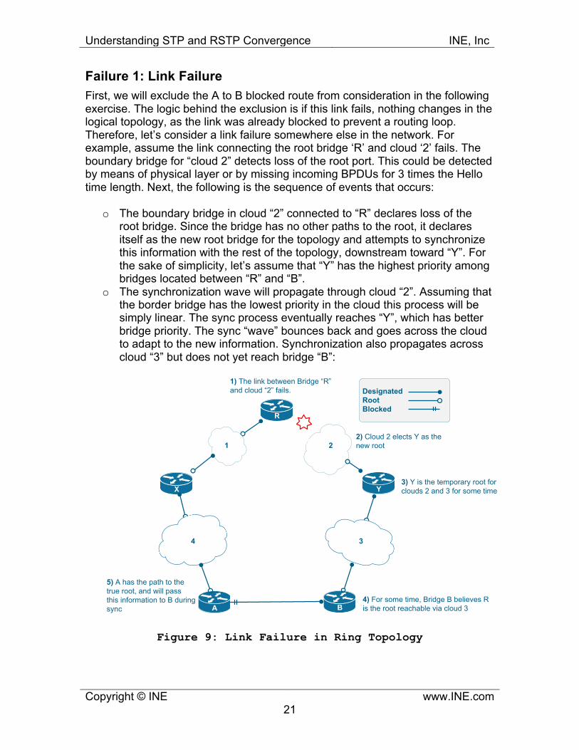
Failure 1: Link Failure First, we will exclude the A to B blocked route from consideration in the following exercise. The logic behind the exclusion is if this link fails, nothing changes in the logical topology, as the link was already blocked to prevent a routing loop. Therefore, let’s consider a link failure somewhere else in the network. For example, assume the link connecting the root bridge ‘R’ and cloud ‘2’ fails. The boundary bridge for “cloud 2” detects loss of the root port. This could be detected by means of physical layer or by missing incoming BPDUs for 3 times the Hello time length. Next, the following is the sequence of events that occurs:
o The boundary bridge in cloud “2” connected to “R” declares loss of the
root bridge. Since the bridge has no other paths to the root, it declares itself as the new root bridge for the topology and attempts to synchronize this information with the rest of the topology, downstream toward “Y”. For the sake of simplicity, let’s assume that “Y” has the highest priority among bridges located between “R” and “B”.
o The synchronization wave will propagate through cloud “2”. Assuming that the border bridge has the lowest priority in the cloud this process will be simply linear. The sync process eventually reaches “Y”, which has better bridge priority. The sync “wave” bounces back and goes across the cloud to adapt to the new information. Synchronization also propagates across cloud “3” but does not yet reach bridge “B”:
DesignatedRootBlocked
R
A B
X Y
1 2
34
3) Y is the temporary root for clouds 2 and 3 for some time
1) The link between Bridge “R” and cloud “2” fails.
2) Cloud 2 elects Y as the new root
4) For some time, Bridge B believes R is the root reachable via cloud 3
5) A has the path to the true root, and will pass this information to B duringsync
Figure 9: Link Failure in Ring Topology

Understanding STP and RSTP Convergence INE, Inc
Copyright © INE www.INE.com 22
o Figure 9 above illustrates the moment when the isolated segment between
“B” and “A” temporary elects “Y” as the root bridge. This segment is still isolated from the true root bridge. Notice that the farther away “Y” is from “R”, the longer it will take for cloud “2” to adapt to the temporary root, due to sync “bounces”. This will cause some traffic disruption inside the isolated segment.
o At this moment, the new inferior root “Y” information reaches “B”. Bridge “B” attempts to synchronize this information with “A”, and bridge “A” immediately responds on a blocked port with better root information (Bridge “R”). Another sync wave starts back from “B” and down to cloud 1. At the end of this process, the segment behind “B” is now synchronized with the true root of the topology and connectivity is restored.
DesignatedRootBlocked
R
A B
X Y
1 2
34
3) A unblocks the alternate path in response to inferior information.
Y is the root
No, R is the root
1) B attempts to sync Y’s information with A2) A responds with R’s
Information to B
Figure 10: Link Failure in Ring Topology, Synchronization

Understanding STP and RSTP Convergence INE, Inc
Copyright © INE www.INE.com 23
o As soon as “A” unblocks its port, it generates a TC event. TC flag is set in
BPDUs sent upstream to the root bridge R and downstream to B. All bridges flush MAC addresses learned on non-edge port and unicast flooding occurs for some time.
The process outlined above leads to the following conclusion: The closer was link failure to the root bridge, the longer time it will take for failure information to propagate to the recovery point (blocked link). The reason is the fact that in symmetric ring topology the blocked port is on the opposite side of the ring from the root bridge and thus a link failing closer to the root isolates large portion of the ring. This indicates that RSTP convergence time is hardly predictable and depends heavily on the failure location. Failure 2: Non-Root Bridge Failure In this scenario, we assume that a non-root bridge physically fails, e.g. reloads. For simplicity, let’s assume that bridge “Y” fails. This failure isolates cloud “3” and bridge “B” from the rest of the topology. Both border bridges in clouds “2” and “3” detect the loss of the connectivity, but they respond differently.
DesignatedRootBlocked
R
A B
X
1 2
34
1) Both border bridges in clouds “2” and “3” detect “loss of link” events. However, only cloud “3” loses connection to the root bridge.
2) Bridge “B” still believes it can reach “R” via cloud “3”. This should be re-synchronized.
Figure 10: Bridge Failure in Ring Topology

Understanding STP and RSTP Convergence INE, Inc
Copyright © INE www.INE.com 24
o The border bridge in cloud “2” does nothing, since it loses connection on
its designated port. It still maintains connectivity to the root bridge and may access the larger part of the topology.
o The border bridge in cloud “3” detects loss of the root port and declares it the new (inferior) root. It then attempts to synchronize this information with the rest of the isolated segment – the remaining part of the cloud “3” and bridge “A”.
o When sync process reaches bridge “A”, this bridge will send an override
BPDU to bridge “B”, announcing the true root bridge “R”. After bridge “B” agrees, bridge “A” unblocks it’s previously blocked port and connects bridge “B” to the rest of the topology. Bridge “B” will further synchronize this information with cloud “3” and connectivity will be restored.
This scenario is very similar to a link failure case. Just like with the link failure, convergence time depends on the failed bridge placement. The closer failed bridge was to the root, the longer it will take to re-synchronize the isolated segmented with the true root bridge.

Understanding STP and RSTP Convergence INE, Inc
Copyright © INE www.INE.com 25
Failure 3: Root Bridge Failure The diagram below illustrates the topology split in two approximately equal halves by the root bridge “R” failure. When both segments detect they have lost the root bridge, each will attempt to elect its own local root.
DesignatedRootBlocked
A B
X Y
1 2
34
Separated Segments will attemptto elect their own root bridges
R
Root bridge fails
Figure 10: Root Bridge Failure in Ring Topology Assuming that “X” and “Y” have the best priority values inside their segments, they are elected as temporary root bridges. There are two possible outcomes: information about inferior root “X” reaches “A” first or information about inferior root bridge Y reaches “A” first.

Understanding STP and RSTP Convergence INE, Inc
Copyright © INE www.INE.com 26
o If Bridge “A” hears about “Y” claiming itself the new root before it hears about bridge “X”, it will use cached information on its root port, believing that the bridge “R” is still the root of the topology. Bridge “A” will immediately respond toward inferior root Y with the “old” root bridge information, even though the old root R is no longer present. After this, clouds “3”, “2” and bridge Y will adapt to this information, assuming they can reach the old root bridge “R” via “A”. The diagram below illustrates this situation:
DesignatedRootBlocked
A B
X Y
1 2
34
2) Bridge A believes R is the Root still. It didn’t hear from X yet
Y is the root
Y is the root
Y is the root
X is the root
X is the root
3) Bridge A receives inferior claim from X and responds with information about R
R is the root
R is the root
R is the root
4) False root bridge R information propagates across the topology
5) Stale root bridge R information stops here
1) X attempts to sync its new root bridge roles with other bridges
Figure 11: Stale Root Information Exists in the Topology
o However, soon after this bridge “A” will hear about inferior root “X” on its
root port. Since this information is received on the root port, the old root “R” information is considered invalid. Based on bridges “X”, “Y” and “A” priorities, a new root bridge is elected and all bridges are synchronized with this information once again, which takes additional time. This is the price RSTP has to pay for not validating cached root bridge information.

Understanding STP and RSTP Convergence INE, Inc
Copyright © INE www.INE.com 27
o If the bridge “A” hears about “X” before it hears about “Y”, it will invalidate cached information about “R” and reach an agreement with “X” about new root bridge. At the moment when inferior information from “Y” reaches “A”, the latter will properly synchronize with “Y” and a new root bridge will be elected. The extra synchronization time required to wipe out old root bridge “R” information is no longer required, as this information is never propagated to “Y”.
The failure of a root bridge results in two separated segments attempting to elect their own root bridges and then merging this information together. Compared to a single link or bridge failure, this takes approximately twice more time to recover, due to the need to synchronize to the separated segments and then merge them, electing single root bridge. The above discussion also illustrates an interesting problem in RSTP. It is known as race condition– depending on event sequencing, resulting convergence times may be different. In the example above, convergence would take longer if “A” receives “Y’s” information first. In the simple ring topology this problem does not result in any serious consequences. However, certain topologies are vulnerable to the full extent of the issue known as “Counting to Infinity”.

Understanding STP and RSTP Convergence INE, Inc
Copyright © INE www.INE.com 28
RSTP Counting to Infinity As we’ve seen from the ring topology, loss of the root bridge results in the slowest convergence case. Worst case scenario is possible when cached information about the original root bridge persists even after the root bridge failure. If, however, the post-failure topology has loops, cached information may persist for much longer, causing major traffic disruption and even bridging loops. Below is a network topology to illustrate the core issue:
DesignatedRootBlocked
1
4 3
5 2
R
I have backup path to “R”via bridge 3.
Figure 12: RSTP Count to Infinity Sample Topology
Imagine that either bridge “R” fails, or the link between Bridge “1” and “R” fails. This will have the following consequences: The root bridge will be removed from the rest of the topology and the network will now have a physical loop. If these two conditions are met, counting to infinity may occur as follows. We will assume that bridge “1” has the highest priority in the following altered network topology in the following discussion.

Understanding STP and RSTP Convergence INE, Inc
Copyright © INE www.INE.com 29
DesignatedRootBlocked
1
4 3
5 2
R
Bridge 1: I lost the root port. I’m the new root.
R is the root
R is the root R is the root
R is the root
Bridge 1 is the root
Bridge 1 is the root
Figure 13: Root Bridge Failed: Remaining Topology has Loop
o Bridge “1” declares itself as a new root and sends corresponding BPDUs
to the downstream bridges. The rest of the topology still believes R is the root. When bridges “2” and “5” receive new BPDUs on their root ports, they accept bridge “1” as the new root.

Understanding STP and RSTP Convergence INE, Inc
Copyright © INE www.INE.com 30
DesignatedRootBlocked
1
4 3
5 2
3) Bridge 4 receives inferior information from 3 and responds with its local information about R! Bridge 4 unblocks the port to 3.
I’m the new root
Bridge 1 is the root
2) Bridge 4 still believes Bridge R is the root
5) Changes root bridge from Bridge 1 to Bridge R
1) Bridge 5 hasn’t yet propagated Bridge 1's information to Bridge 4
1 is the root
1 is the root
R is the root
1 is the root
4) Bridge 3 propagates information about non-existent bridge R further, overriding the new topology
R is the root
Figure 14: Stale Root Information is injected in the loop
o Using Figure 14 for illustration, we can now assume that BPDU with
bridge “1”’s information sent via bridge “2” reaches bridge “4” before the same information sent via bridge “5”. What this means is bridge “4” learns about bridge “1” being the new root via its blocked port and classifies this information as inferior. Immediately following this, bridge “4” sends a proposal to bridge “3” indicating the now deceased bridge “R” as the root. Bridge “3” accepts this information, and bridge “4” unblocks its previously blocked port. Now, both bridges “3” and “4” believe bridge “R” is the root bridge:

Understanding STP and RSTP Convergence INE, Inc
Copyright © INE www.INE.com 31
DesignatedRootBlocked
1
4 3
5 2
3) Bridge 4 informs Bridge 3 that 1 is the new root, and Bridge 3 accepts that. Bridge 4 blocks the port to Bridge 3
6) Bridge 1 accepts non-existent Bridge R as the root!
Bridge 1 is the root
2) Bridge 4 discards bridge R as the root and accepts Bridge 1
5) Bridge 2 believes R is the root and propagates this information to Bridge 11) Bridge 5 propagated
Bridge 1 information to Bridge 4
Bridge 1 is the root
R is the root
4) Bridge 3 propagates the true bridge 1 information to Bridge 2 but Bridge 2 has already sent information about bridge R futher...
Bridge 1 is the root
Agree, Bridge 1 is the root, my port designated
R is the root
R is the root
Figure 15: Stale and Fresh information Chase each other
o Next, the information sent by bridge “1” via bridge “5” reaches bridge “4”. Seeing that bridge “R” is lost, bridge “4” accepts the new root bridge and attempt to synchronize this information with bridge “3”, which just has learned about non-existent bridge “R” being the root (See Figure 15). However, at this moment, bridge “3” already propagated information about the non-existent bridge “R” to bridge “2”! Thus, even though Bridge 3 adapts to the new root information, old information still circulates inside the looped topology. Effectively, new information about Bridge 1 is chasing the old information about bridge R.
o Old information will eventually reach to bridge “1” and make it elect a root
port pointing toward the fictitious root bridge “R” (See Figure 14). Soon after this, Bridge “1” will catch its own information and adapt a different topology. The net result is oscillation in port roles and transient bridging loop, which happens due to the fact that bridge “4” unblocked its port. Old information will cycle in the topology until its Message_Age reaches Max_Age. This is known as “counting to infinity” and hence the name to the problem. After counting to infinity is completed, old information is eliminated and all bridges finally agree on the new root.

Understanding STP and RSTP Convergence INE, Inc
Copyright © INE www.INE.com 32
The above problem is only possible due to the “race condition” found in RSTP. It may or may not manifest itself under some conditions, but it poses serious problem in deployments that have many redundant paths. The best protection against counting to infinity is maintaining minimum possible redundancy with RSTP, e.g. sticking with simple triangle or ring topologies. Counting to infinity can seriously slow down convergence in large topologies of tens of bridges, especially those that has rich set of redundant link. Some modeling has shown convergence times over 30 seconds in complex topologies. This behavior is explained by the time it takes to process BPDUs in heavy loaded and re-converging topology.

Understanding STP and RSTP Convergence INE, Inc
Copyright © INE www.INE.com 33
RSTP Conclusions RSTP is often claimed to converge in less than one second. This article illustrates the fact that this claim could only be accurate in particular conditions. First, the topology needs to be small, about 3-5 bridges. Second, redundancy should be limited to one redundant path, to avoid looped topologies after a single link failure. Lastly, root bridge and its connections should be protected by all means, e.g. by use of redundant supervisors and bundled links. If you are looking towards predictable performance with complex topologies, your natural choice could be using Layer 3 routing and IGP-based re-convergence. However, if Layer 2 is a must, consider using some other layer 2 protection protocols, such as Resilient Ethernet Protocols (REP) or Ethernet Automatic Protection Switching (EAPS). These protocols are specifically adapted to be used in ring topologies, employing the fact that there is only one blocked link in this type of topology. In situations like this, the bridge blocking the alternate path only need to know that there is a failure anywhere in the topology to safely unblock the backup path. Some ring protection protocols are proprietary, such as REP, but Extreme Network’s EAPS has been standardized as RFC. Self-Assessment The reader is recommended to try answering the following questions on his own to validate and further expand understanding of the topics discussed in this blog post.
o Why can’t legacy STP converge faster than 2xForward_Time? o Why there is no need to relay BPDUs with RSTP? o Why RSTP may safely ignore non-superior proposals on blocked ports? o Could a full-duplex link connect to a shared topology? o What is the main factor that makes counting to infinity possible with
RSTP? o What happens if the number of nodes in ring topology is larger than
Max_Age? o Is it possible to use diffused computations (aka DUAL) to implement
robust RSTP? o What would you suggest to reduce the effect of unicast flooding but
maintain its effect of address learning? o How is MAC address purpose different from IP address purpose? o How would you quickly detect and signal a fault in ring topology?

Understanding STP and RSTP Convergence INE, Inc
Copyright © INE www.INE.com 34
Further Reading o Understanding STP Topology Changes:
http://www.cisco.com/en/US/tech/tk389/tk621/technologies_tech_note09186a0080094797.shtml
o Understanding STP Timer: http://www.cisco.com/en/US/tech/tk389/tk621/technologies_tech_note09186a0080094954.shtml
o Understanding and Mitigating the Effect of Counting to Infinity in Ethernet Network: http://research.yahoo.com/files/ToN.pdf
o Understanding Rapid Spanning Tree Protocol: http://www.cisco.com/en/US/tech/tk389/tk621/technologies_white_paper09186a0080094cfa.shtml
o IEEE 802.1D document, includes RSTP: http://standards.ieee.org/getieee802/download/802.1D-2004.pdf