Embed Size (px)
Citation preview
Application ReportSLVA448–January 2011
Understanding Photovoltaics and the Market ForcesBehind Them
Nagarajan Sridhar ................................................. Solar and Energy Management Lab, Texas Instruments
ABSTRACT
Forecasted demand in energy is expected to double through 2030 and could outstrip supply. Furthermore,with increasing energy prices in history, advancements in “clean/green technologies” is creating a wave ofopportunity. The last 2 to 3 decades of improvement have made alternative energies more attractive andless expensive. Solar industry is the fastest growing segment in the alternative energy sector where globalresources are plentiful. The market and the technology of the solar industry is discussed in this applicationnote.
1 Introduction
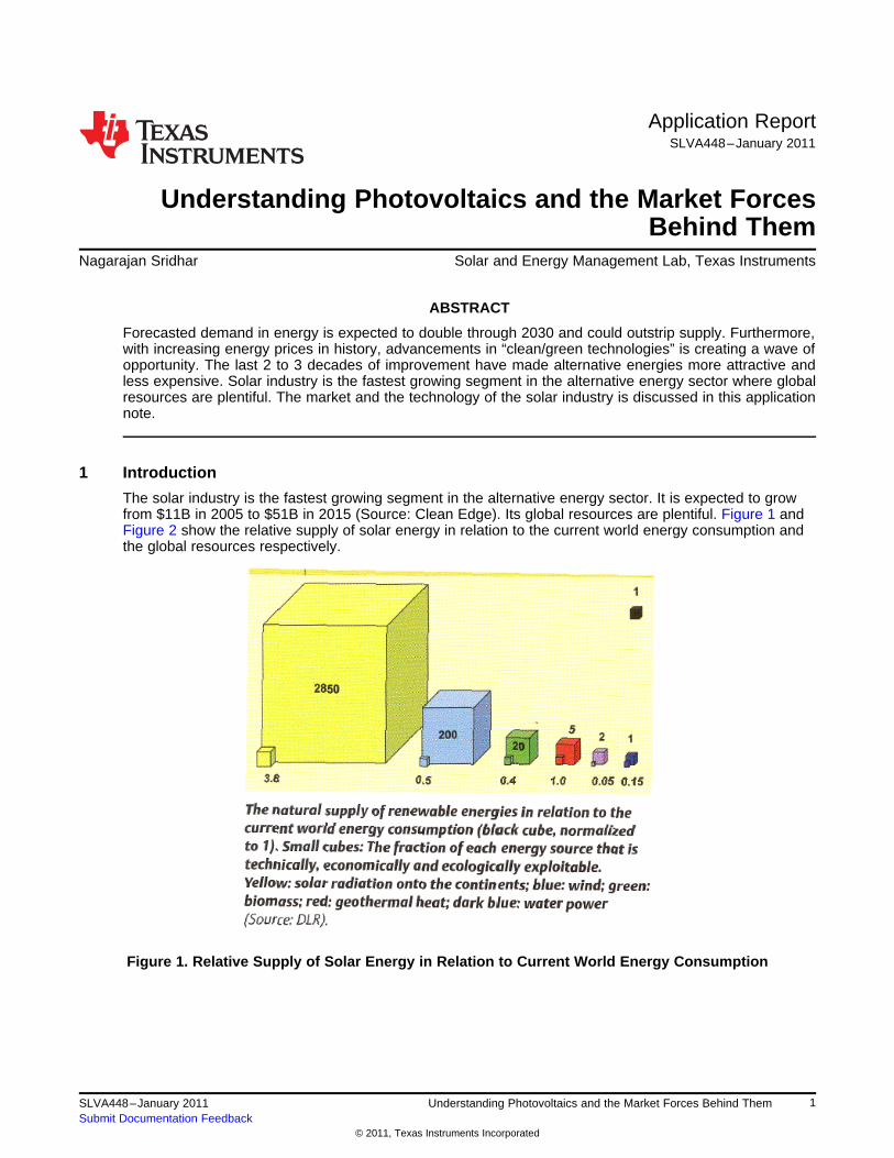
The solar industry is the fastest growing segment in the alternative energy sector. It is expected to growfrom $11B in 2005 to $51B in 2015 (Source: Clean Edge). Its global resources are plentiful. Figure 1 andFigure 2 show the relative supply of solar energy in relation to the current world energy consumption andthe global resources respectively.
Figure 1. Relative Supply of Solar Energy in Relation to Current World Energy Consumption
1SLVA448–January 2011 Understanding Photovoltaics and the Market Forces Behind ThemSubmit Documentation Feedback
© 2011, Texas Instruments Incorporated
Solar Technology www.ti.com
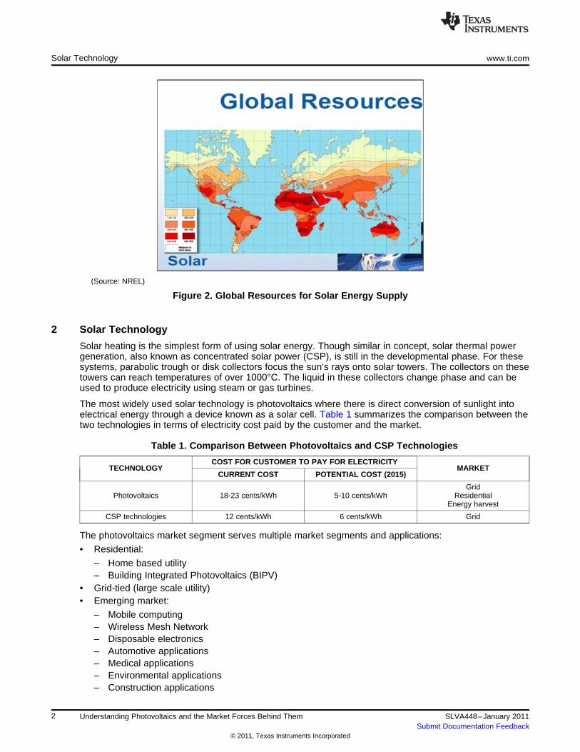
(Source: NREL)
Figure 2. Global Resources for Solar Energy Supply
2 Solar Technology
Solar heating is the simplest form of using solar energy. Though similar in concept, solar thermal powergeneration, also known as concentrated solar power (CSP), is still in the developmental phase. For thesesystems, parabolic trough or disk collectors focus the sun’s rays onto solar towers. The collectors on thesetowers can reach temperatures of over 1000°C. The liquid in these collectors change phase and can beused to produce electricity using steam or gas turbines.
The most widely used solar technology is photovoltaics where there is direct conversion of sunlight intoelectrical energy through a device known as a solar cell. Table 1 summarizes the comparison between thetwo technologies in terms of electricity cost paid by the customer and the market.
Table 1. Comparison Between Photovoltaics and CSP Technologies
COST FOR CUSTOMER TO PAY FOR ELECTRICITYTECHNOLOGY MARKET
CURRENT COST POTENTIAL COST (2015)
GridPhotovoltaics 18-23 cents/kWh 5-10 cents/kWh Residential
Energy harvest
CSP technologies 12 cents/kWh 6 cents/kWh Grid
The photovoltaics market segment serves multiple market segments and applications:
• Residential:
– Home based utility– Building Integrated Photovoltaics (BIPV)
• Grid-tied (large scale utility)• Emerging market:
– Mobile computing– Wireless Mesh Network– Disposable electronics– Automotive applications– Medical applications– Environmental applications– Construction applications
2 Understanding Photovoltaics and the Market Forces Behind Them SLVA448–January 2011Submit Documentation Feedback
© 2011, Texas Instruments Incorporated
www.ti.com Solar Cell Operation
– Military and aerospace applications
3 Solar Cell Operation
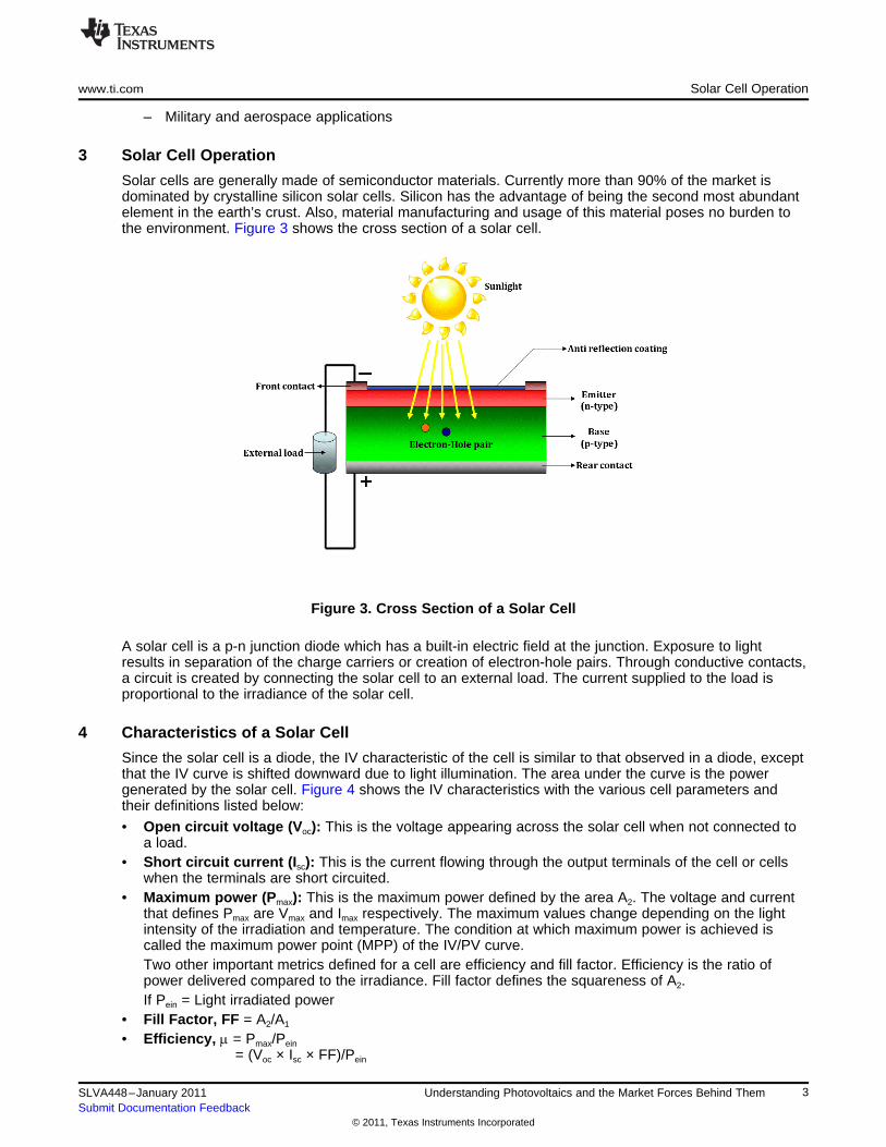
Solar cells are generally made of semiconductor materials. Currently more than 90% of the market isdominated by crystalline silicon solar cells. Silicon has the advantage of being the second most abundantelement in the earth’s crust. Also, material manufacturing and usage of this material poses no burden tothe environment. Figure 3 shows the cross section of a solar cell.
Figure 3. Cross Section of a Solar Cell
A solar cell is a p-n junction diode which has a built-in electric field at the junction. Exposure to lightresults in separation of the charge carriers or creation of electron-hole pairs. Through conductive contacts,a circuit is created by connecting the solar cell to an external load. The current supplied to the load isproportional to the irradiance of the solar cell.
4 Characteristics of a Solar Cell
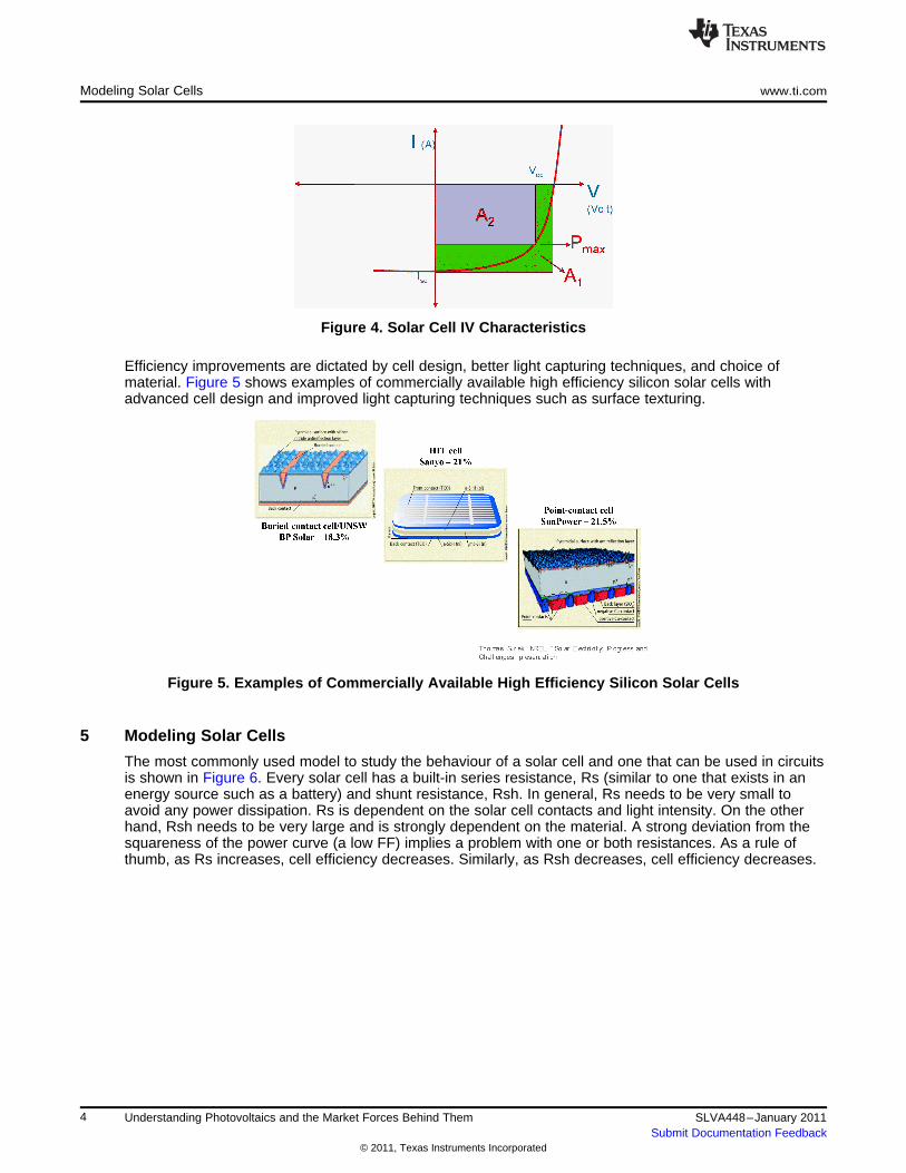
Since the solar cell is a diode, the IV characteristic of the cell is similar to that observed in a diode, exceptthat the IV curve is shifted downward due to light illumination. The area under the curve is the powergenerated by the solar cell. Figure 4 shows the IV characteristics with the various cell parameters andtheir definitions listed below:
• Open circuit voltage (Voc): This is the voltage appearing across the solar cell when not connected toa load.
• Short circuit current (Isc): This is the current flowing through the output terminals of the cell or cellswhen the terminals are short circuited.
• Maximum power (Pmax): This is the maximum power defined by the area A2. The voltage and currentthat defines Pmax are Vmax and Imax respectively. The maximum values change depending on the lightintensity of the irradiation and temperature. The condition at which maximum power is achieved iscalled the maximum power point (MPP) of the IV/PV curve.Two other important metrics defined for a cell are efficiency and fill factor. Efficiency is the ratio ofpower delivered compared to the irradiance. Fill factor defines the squareness of A2.If Pein = Light irradiated power
• Fill Factor, FF = A2/A1
• Efficiency, m = Pmax/Pein
●Efficiency, m = (Voc × Isc × FF)/Pein
3SLVA448–January 2011 Understanding Photovoltaics and the Market Forces Behind ThemSubmit Documentation Feedback
© 2011, Texas Instruments Incorporated
Modeling Solar Cells www.ti.com
Figure 4. Solar Cell IV Characteristics
Efficiency improvements are dictated by cell design, better light capturing techniques, and choice ofmaterial. Figure 5 shows examples of commercially available high efficiency silicon solar cells withadvanced cell design and improved light capturing techniques such as surface texturing.
Figure 5. Examples of Commercially Available High Efficiency Silicon Solar Cells
5 Modeling Solar Cells
The most commonly used model to study the behaviour of a solar cell and one that can be used in circuitsis shown in Figure 6. Every solar cell has a built-in series resistance, Rs (similar to one that exists in anenergy source such as a battery) and shunt resistance, Rsh. In general, Rs needs to be very small toavoid any power dissipation. Rs is dependent on the solar cell contacts and light intensity. On the otherhand, Rsh needs to be very large and is strongly dependent on the material. A strong deviation from thesquareness of the power curve (a low FF) implies a problem with one or both resistances. As a rule ofthumb, as Rs increases, cell efficiency decreases. Similarly, as Rsh decreases, cell efficiency decreases.
4 Understanding Photovoltaics and the Market Forces Behind Them SLVA448–January 2011Submit Documentation Feedback
© 2011, Texas Instruments Incorporated
www.ti.com Solar Cells to Modules
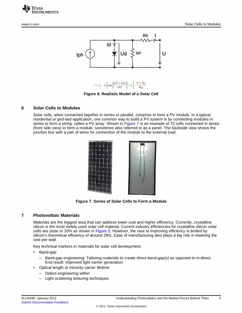
Figure 6. Realistic Model of a Solar Cell
6 Solar Cells to Modules
Solar cells, when connected together in series or parallel, comprise to form a PV module. In a typicalresidential or grid-tied application, one common way to build a PV system is by connecting modules inseries to form a string, called a PV array. Shown in Figure 7 is an example of 72 cells connected in series(front side view) to form a module, sometimes also referred to as a panel. The backside view shows thejunction box with a pair of wires for connection of the module to the external load.
Figure 7. Series of Solar Cells to Form a Module
7 Photovoltaic Materials
Materials are the biggest area that can address lower cost and higher efficiency. Currently, crystallinesilicon is the most widely used solar cell material. Current industry efficiencies for crystalline silicon solarcells are close to 20% as shown in Figure 5. However, the race to improving efficiency is limited bysilicon’s theoretical efficiency of around 28%. Ease of manufacturing also plays a big role in lowering thecost per watt.
Key technical markers in materials for solar cell development:
• Band-gap
– Band-gap engineering: Tailoring materials to create direct band-gap(s) as opposed to in-direct.End result: Improved light carrier generation.
• Optical length or minority carrier lifetime
– Defect engineering within– Light scattering texturing techniques
5SLVA448–January 2011 Understanding Photovoltaics and the Market Forces Behind ThemSubmit Documentation Feedback
© 2011, Texas Instruments Incorporated

Cell Structures www.ti.com
• Carrier Mobility
– Reduce lattice disorder• Absorption co-efficient
– Tailor materials to improve the spectral response
Based on these criteria, several materials have emerged in the market. Table 2 summarizes the varioussolar cell materials, their features, their potential applications, and the challenges they face in becomingcommercially viable.
Table 2. Materials: One of the Biggest Challenges in Making a Solar Cell Commercially
MATERIAL FEATURES DISADVANTAGE APPLICATIONS
Bulk Crystalline Si Efficiency close to 18–20% Expensive ($4/Wpeak) material Residential and militarywastage
III-V / II-VI Highest efficiencies in the market Very expensive Military and space, CSP
Poly-Si Cheaper than mono-crystalline SI Material wastage. Supply is an Residential and gridissue.
Thin Poly-Si Low cost – Compatible with Efficiency below 15% Portable, medical, automotivefilm current IC and MEMS mfg manufacturing method: direct dep. (ultra-low power) Integrated with
or anneal? current process technologiesgrid and residential
Hydrogenated Low cost – Compatible with Efficiency ~ 10% Portable, medical, automotiveamorphous Si current IC and MEMS mfg (ultra-low power) Integrated with
current process technologiesgrid and residential
CdTe High efficiency ~ 16% Te is rare. Process challenge. Large area (grid), although still aCd is toxic: DIsposal issue. challenge
CIS/CIGS Ideal material for solar cell: Efficiency degrades. Processing a Large area: potentially canSuitable band-gap and high challenge. incorporate this as a TF in Si ICabsorption. Hence, lowest technologiesthickness. High efficiency ~ 19%
OrganicsVery cheap – Low cost Still an emerging market. No clear Portable, medical, automotivePlastic Dye sensitized manufacturing choice of material. (ultra-low power)
materials
Table 3 lists the manufacturing methods, advantages, and challenges for these solar cells.
Table 3. Solar Cell Manufacturing
MANUFACTURINGMATERIAL ADVANTAGES DISADVANTAGESMETHOD
Bulk (c-Si, poly-Si, CZ cystal pulling ● Established ● Very expensiveGaAs) ● High efficiency ● Supply issue for large area applications
● PECVD ● Low temperature process ● Low throughputThin film ● Printing ● Compatible with low cost ● Annealing processes not standardized(a-Si:H, poly-Si, CIS, ● Vacuum deposition substrates ● Printing processes not standardizedCIGS, CdTe, flex-Si) ● Low cost
● Inkjet printing ● Very inexpensive ● Manufacturing not dialed-in due to materialsOrganic ● Spin coating being an emerging market
8 Cell Structures
To take maximum advantage of the sun spectrum, cell structures are designed using multi-junctions anddissimilar materials. Multi-junction solar cells are made by stacking individual single junction cells with theband-gap descending from the top to the bottom of the cell. The purpose is to have the highest energyphotons absorbed by the top junction and the lower energy photons transmitted to be absorbed by thelower band-gap solar cells. Multi-junctions are usually built using compound semiconductorhetero-structures using III-V and II-V materials.
6 Understanding Photovoltaics and the Market Forces Behind Them SLVA448–January 2011Submit Documentation Feedback
© 2011, Texas Instruments Incorporated

www.ti.com Concentrated Photovoltaics (CPV)
9 Concentrated Photovoltaics (CPV)
Concentrated photovoltaics, known as CPV, is an emerging solar cell technology that utilizes the benefitsof multi-junctions using III-V and II-V materials. The advantages of this technology are two-fold; one is dueto the high efficiency that is inherent from the compound semiconductors and secondly, the concentratedintensity that is 10× to 1000× the intensity that is typically used in traditional solar cells. Currently, the costof these cells is much higher than traditional solar cells. However, this technology has potentially thelowest cost per watt due to the advantage of the higher efficiency it enjoys, a drastic reduction in thematerial used, and the automatic cost reduction that will be reflected from economy of scale when itreaches large scale production.
10 Moving Forward
Innovation in cell and module design will continue to be the driver for achieving lower cost per watt. This istrue for all solar cell markets from silicon to organic solar as well as CPV, which is to reach below $1/W.Although there are several approaches being taken to achieve this goal, some through better technologyto improve higher efficiency, which in turn will deliver more wattage for a given cell, whereas others aretaking the low cost manufacturing and ease of installation approach. Finally, the concept of smart moduleis being commercialized where electronics are built into a module to maximize the energy being generatedfrom the module. TI plays into this downstream market of this chain by supplying components to key micromodule based electronics customers.
11 References1. DLR, Renewable Energy, Roland Wengenmayr and Thomas Buhrke, Wiley Tech, 20082. NREL, Solar Electricity Progress and Challenges, Thomas Surek
7SLVA448–January 2011 Understanding Photovoltaics and the Market Forces Behind ThemSubmit Documentation Feedback
© 2011, Texas Instruments Incorporated
IMPORTANT NOTICE
Texas Instruments Incorporated and its subsidiaries (TI) reserve the right to make corrections, modifications, enhancements, improvements,and other changes to its products and services at any time and to discontinue any product or service without notice. Customers shouldobtain the latest relevant information before placing orders and should verify that such information is current and complete. All products aresold subject to TI’s terms and conditions of sale supplied at the time of order acknowledgment.
TI warrants performance of its hardware products to the specifications applicable at the time of sale in accordance with TI’s standardwarranty. Testing and other quality control techniques are used to the extent TI deems necessary to support this warranty. Except wheremandated by government requirements, testing of all parameters of each product is not necessarily performed.
TI assumes no liability for applications assistance or customer product design. Customers are responsible for their products andapplications using TI components. To minimize the risks associated with customer products and applications, customers should provideadequate design and operating safeguards.
TI does not warrant or represent that any license, either express or implied, is granted under any TI patent right, copyright, mask work right,or other TI intellectual property right relating to any combination, machine, or process in which TI products or services are used. Informationpublished by TI regarding third-party products or services does not constitute a license from TI to use such products or services or awarranty or endorsement thereof. Use of such information may require a license from a third party under the patents or other intellectualproperty of the third party, or a license from TI under the patents or other intellectual property of TI.
Reproduction of TI information in TI data books or data sheets is permissible only if reproduction is without alteration and is accompaniedby all associated warranties, conditions, limitations, and notices. Reproduction of this information with alteration is an unfair and deceptivebusiness practice. TI is not responsible or liable for such altered documentation. Information of third parties may be subject to additionalrestrictions.
Resale of TI products or services with statements different from or beyond the parameters stated by TI for that product or service voids allexpress and any implied warranties for the associated TI product or service and is an unfair and deceptive business practice. TI is notresponsible or liable for any such statements.
TI products are not authorized for use in safety-critical applications (such as life support) where a failure of the TI product would reasonablybe expected to cause severe personal injury or death, unless officers of the parties have executed an agreement specifically governingsuch use. Buyers represent that they have all necessary expertise in the safety and regulatory ramifications of their applications, andacknowledge and agree that they are solely responsible for all legal, regulatory and safety-related requirements concerning their productsand any use of TI products in such safety-critical applications, notwithstanding any applications-related information or support that may beprovided by TI. Further, Buyers must fully indemnify TI and its representatives against any damages arising out of the use of TI products insuch safety-critical applications.
TI products are neither designed nor intended for use in military/aerospace applications or environments unless the TI products arespecifically designated by TI as military-grade or "enhanced plastic." Only products designated by TI as military-grade meet militaryspecifications. Buyers acknowledge and agree that any such use of TI products which TI has not designated as military-grade is solely atthe Buyer's risk, and that they are solely responsible for compliance with all legal and regulatory requirements in connection with such use.
TI products are neither designed nor intended for use in automotive applications or environments unless the specific TI products aredesignated by TI as compliant with ISO/TS 16949 requirements. Buyers acknowledge and agree that, if they use any non-designatedproducts in automotive applications, TI will not be responsible for any failure to meet such requirements.
Following are URLs where you can obtain information on other Texas Instruments products and application solutions:
Products Applications
Audio www.ti.com/audio Communications and Telecom www.ti.com/communications
Amplifiers amplifier.ti.com Computers and Peripherals www.ti.com/computers
Data Converters dataconverter.ti.com Consumer Electronics www.ti.com/consumer-apps
DLP® Products www.dlp.com Energy and Lighting www.ti.com/energy
DSP dsp.ti.com Industrial www.ti.com/industrial
Clocks and Timers www.ti.com/clocks Medical www.ti.com/medical
Interface interface.ti.com Security www.ti.com/security
Logic logic.ti.com Space, Avionics and Defense www.ti.com/space-avionics-defense
Power Mgmt power.ti.com Transportation and www.ti.com/automotiveAutomotive
Microcontrollers microcontroller.ti.com Video and Imaging www.ti.com/video
RFID www.ti-rfid.com Wireless www.ti.com/wireless-apps
RF/IF and ZigBee® Solutions www.ti.com/lprf
TI E2E Community Home Page e2e.ti.com
Mailing Address: Texas Instruments, Post Office Box 655303, Dallas, Texas 75265Copyright © 2011, Texas Instruments Incorporated