Embed Size (px)
Citation preview
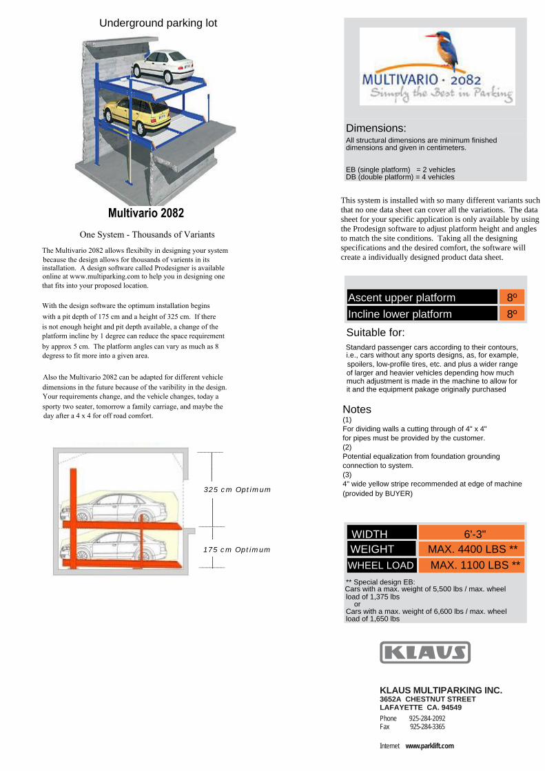
Underground parking lot
Notes(1)
(2)
(3)
Dimensions:All structural dimensions are minimum finished
EB (single platform) = 2 vehiclesDB (double platform) = 4 vehicles
Ascent upper platform 8º
Incline lower platform 8º
Suitable for:
or
_______
_______
_______
____
___
____
___
______
____
____
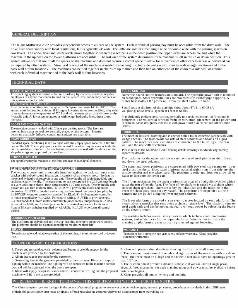
325 cm Optimum
175 cm Optimum
dimensions and given in centimeters.
that no one data sheet can cover all the variations. The data
sheet for your specific application is only available by using
the Prodesign software to adjust platform height and angles
to match the site conditions. Taking all the designing
specifications and the desired comfort, the software will
for pipes must be provided by the customer.
Potential equalization from foundation grounding
i.e., cars without any sports designs, as, for example,
of larger and heavier vehicles depending how much
Standard passenger cars according to their contours,
it and the equipment pakage originally purchased
This system is installed with so many different variants such
Multivario 2082One System - Thousands of Variants
The Multivario 2082 allows flexibilty in designing your systembecause the design allows for thousands of varients in its installation. A design software called Prodesigner is availableonline at www.multiparking.com to help you in designing onethat fits into your proposed location.
With the design software the optimum installation beginswith a pit depth of 175 cm and a height of 325 cm. If thereis not enough height and pit depth available, a change of theplatform incline by 1 degree can reduce the space requirementby approx 5 cm. The platform angles can vary as much as 8 degress to fit more into a given area.
Also the Multivario 2082 can be adapted for different vehicledimensions in the future because of the varibility in the design.Your requirements change, and the vehicle changes, today asporty two seater, tomorrow a family carriage, and maybe theday after a 4 x 4 for off road comfort.
much adjustment is made in the machine to allow for
For dividing walls a cutting through of 4" x 4"
create a individually designed product data sheet.
4" wide yellow stripe recommended at edge of machine
WIDTH 6'-3" WEIGHT MAX. 4400 LBS **
WHEEL LOAD MAX. 1100 LBS **
(provided by BUYER)
connection to system.
spoilers, low-profile tires, etc. and plus a wider range
** Special design EB: Cars with a max. weight of 5,500 lbs / max. wheel
load of 1,375 lbs
load of 1,650 lbs Cars with a max. weight of 6,600 lbs / max. wheel
Internet www.parklift.com
Fax 925-284-3365Phone 925-284-2092LAFAYETTE CA. 945493652A CHESTNUT STREETKLAUS MULTIPARKING INC.

Vehicle top 4'-11" / Vehicle bottom 4'-11" Vehicle top 4'-11" / Vehicle bottom 4'-11"Aptitude top 1 degree / bottom 1 degree
Vehicle top 4'-11" / Vehicle bottom 4'-11"
Aptitude top 5 degree / bottom 1 degreeVehicle top 4'-11" / Vehicle bottom 4'-11"
Aptitude top 5 degree / bottom 1 degreeVehicle top 4'-11" / Vehicle bottom 4'-11"
Aptitude top 5 degree / bottom 5 degree Aptitude top 5 degree / bottom 1 degreeVehicle top 4'-11" / Vehicle bottom 4'-11"
Aptitude top 1 degree / bottom 1 degree Varient 1 position top Varient 1 position bottom
Varient 2 position top Varient 2 position bottom
Varient 3 position top Varient 3 position bottom

Seismic Bracing
The tie rod bracing points for the Multivario 2082 are shown above
Varient 4 position top Varient 4 position downAptitude top 1 degree / bottom 1 degreeAptitude top 1 degree / bottom 1 degree
Vehicle top 4'-11" / Vehicle bottom 5'-11"Vehicle top 4'-11" / Vehicle bottom 5'-11"

Approach
14 %
Installation data
Free space for longitudinal and vertical ducts (e.g. ventilation)
B1 B1 B1 B1
B2B3B2
EB EB DB DB
Approach level
Free space for vertical pipelines,ventilation branch canals
Free space for horizontalducting
Free space only applicable if vehicleis parked forwards = FRONT FIRSTand driver’s door on the left side.
( ) = Dimensions in bracketsillustrate an example for usableplatform width 230/460 cm.
Example for ventilation branchcanal and/or vertical pipelines.
The illustrated maximum approach angles must not be exceeded. Exceeding these slopes will causemaneuvering problems and will restrict car sizes on the parking system.
2 %
4" 4" 4" 4"(8'-8") (8'-7") (16'-2") (16'-3")
1'-2" 1'-2" 1'-2" 1'-2"
1'-0"
8"8"
Max.
7'-1"
3'-9"
Max.
_ _> 8" > 8"(24'-1") (15'-11")
B1, B2, B3 = (Norm, should we say this may vary?)
(8'-4")
RANGE OF APPLICATIONThis parking system is suitable for self parking by owners, renters, regularemployees or anyone that can be trained on the system. The public may not park onthis system without a valet.ENVIRONMENTAL CONDITIONS
system must be installed indoors. If lifting or lowering times are specified, they referto an environmental temperature of 72° F and with system set up directly next to thehydraulic unit. At lower temperatures or with longer hydraulic lines, these timesincrease.
SPACE NUMBERINGStandard space numbering is left to right with the empty space located in the firstbay on the left. The empty space can be moved to another bay or even outside thenormal machine if needed. The numbering sequence planned will be shown on theshop drawings and approved by the client.
The hydraulic power unit is normally installed against the back wall on a metalbracket with rubber sound insulation. It consists of an electric motor, hydraulicmotor and hydraulic oil reservoir in one unit. The hydraulic oil is biodegradable and
CORROSION PROTECTIONThe platforms are galvanized and the steel framing members are powder coated.The platforms should be cleaned annually to maximize their life.
SERVICETo maintain safe and reliable operation of the machine, it must be serviced twice peryear.
WARRANTYTo machine has a complete one year parts and labor warranty. Klaus providesextended warranties.
machine are provided by the customer.2. All pit drainage is provided by the customer.3. General lighting in the garage is provided by the customer. Klaus will supplylighting within the machine. The lighting will be connected to the machine controlbox and will be activated when the doors are open.4. Klaus will supply design assistance and will confirm in writing that the proposedmachine will fit in the space provided.
SOUND CONTROLNumerous sound control features are standard. The hydraulic power unit is mountedon rubber pads. Steel hydraulic lines are mounted with rubber pipe supports. Arubber hose isolates the power unit from the steel hydraulic lines.
Sound tests at the front of the machine show about 67dB to 69dB (Aweighting) noise levels (speech at i foot is 68db).
In multifamily podium construction, normally no special construction for sound isperformed. For residential or wood frame construction, placement of the power unitis critical. Klaus designers will assist with power unit placement and other soundissues.
STRUCTURALThe machine has steel framing and is anchor bolted to the concrete garage slab withwedge anchors. The framework consists of steel columns and beams on a gridpattern. The machines steel columns are connected to the building at the rear
report for details.
The platforms for the upper and lower cars consist of steel platforms that ride up
The upper and lower platforms are constructed with two steel side members, threesteel cross members, ribbed steel platform material which runs from side memberto side member and one wheel stop. The platform is solid and does not allow oil orwater to drip onto the lower cars.
The lifting mechanism for the upper platforms consists of a hydraulic cylinder whichraises the rear of the platform. The front of the platform is raised via a chain whichruns on chain sprockets. There are safety switches that stop the machine in theevent the chain goes loose for any reason. The platforms are suspended at the 4corners and are guided along the front support columns.
The lower platforms are moved via an electric motor located on each platform. Themotor drives a sprocket that runs along a chain at grade level. The platform runs onsteel guide rails and can be moved manually without power by releasing the brakeon the electric motor.
The machine includes several safety devices which include chain monitoringsystems, and safety locks for the upper platforms. When a user is inside themachine all platforms are mechanically protected against lowering.
5. Klaus will prepare shop drawings showing the location of all components.
6. The customer must close off the left and rightfence. The fence must be 8' high and the lower 5than 1/2" inch.
8. Klaus provides all control wiring and conduit.
DOORS AND CONTROL SYSTEMS
1. The pit and surrounding walls, columns and beams to provide support for the
The Klaus Multivario 2082 provides independent access to all cars on the system. Each individual parking bay must be accessible from the drive aisle. The
drive aisle shall comply with local regulations, but is typically 24' wide. The 2082 are sold in either single wide or double wide with the parking spaces on
two levels. The upper level and lower levels move together so when the machine is in the down position the upper levels are accessible and when the
machine in the up position the lower platforms are accessible. The last user of the system determines if the machine is left in the up or down position. This
system allows for full use of all the spaces on the machine and does not require a vacant space to allow for movement of other cars to access a individual car
as required by other systems. Structural bracing of the machine is made by attaching it to two side walls with 16mm tie rods at eight locations and to theback wall at four locations. The machines can be tied together in chains of up to three and then tied on either end of the chain to a side wall or columnwith each individual machine tied to the back wall at four locations.
The machine comes standard with 2 keys per parking space. The keys are inserted into a user control box centrally placed on the system. Electricdoors are available. Infrared control transmitters are available.
and down the steel columns.
wall and the side walls or columns.
Environmental conditions for the systems: Temperature range 14° to 104° F. The
The sprinklers may be mounted at the front and rear of each level if needed.SPRINKLER SYSTEM
ELECTRICAL REQUIREMENTS AND HYDRAULIC UNIT
environmentally friendly. The electric motor can be supplied in a 208 volt (perferred)or a 240 volt single phase. Both types require a 30 amp circuit. One hydraulic unitpower unit can rum multiple lifts. KLAUS will provide the motor and motor
TECHNICAL DATA
GENERAL DESCRIPTION
SCOPE OF WORK CLARIFICATIONS
WE RESERVE THE RIGHT TO CHANGE THIS SPECIFICATION WITHOUT FURTHER NOTICE
Please refer to the MultiVario 2082 bracing details drawing and Merkle engineering
The Klaus company reserves the right in the course of technical progress to use newer or other technologies, systems, processes, proceduresof their obligations other than those originally offered provided the customer derives no disadvantage from their doing so.
7. The customer must provide a 30 amp 3 phase 2circuit & fused disconnect for each machine groupinstallation begins.
controller. BUYER to conduit and wiring: a) from fused disconnect (supplied byby BUYER) to motor controller (supplied by KLAUS); b) from motor controller to motor (supplied by KLAUS). For control wiring, BUYER to provide empty3/4 inch conduit: 1) from motor controller to junction box (supplied by KLAUS)at rear of each lift; and 2) from junction box to desired key switch locations atfront of lift (key switches supplied by KLAUS). KLAUS to perform all controlwiring.
sides of the machine with a wall orfeet must have no openings greater
or standards in the fullfillment
08 volt (or 240 volt single phase) and power must be available before