Embed Size (px)
Citation preview

Underdamped Second-Order Systems Overshoot Control
P. B. Moura Oliveira*. Damir Vrančić **
* CIDESD, Department of Engineering, School of Sciences and Technology, 5001–801 Vila Real Portugal (Tel: +351-259-350339; e-mail: oliveira@ utad.pt).
** Department of Systems and Control, Jožef Stefan Institute, Jamova cesta 39, Ljubljana, Slovenia (e-mail: [email protected])
Abstract: The paper addresses the problem of decreasing the overshoot for underdamped second-order systems. A new technique to control the overshoot is proposed, which is based on Posicast control and proportional integral and derivative (PID) control, which performs switching between two controllers. The aim is to use open-loop feedforward control to increase tracking performance and PID control to deal with disturbance rejection. It has been shown that the proposed control scheme can have some advantages over the classical approaches without switching capabilities.
Keywords: PID control, Posicast control, Second-order systems, Anti-windup.
1. INTRODUCTION
A deadbeat-response is often considered as an optimal closed-loop response, since it achieves minimum rise-time, no steady-state error and no overshoot, in a minimum number of time-steps. From the authors’ experience in designing second-order systems control, an important question is: how to achieve small or zero overshoot in the closed-loop step-response for the second-order systems? This is a relevant issue, as there are many control applications in practice dealing with systems dynamics represented by second order models and requiring minimum overshoot. The representatives of such systems can be found in robot control (Singhose and Seering, 2005), crane control (Sorensen et al., 2007) vibration control (Singer and Seering, 1990; Singhose, 2009; Singh and Singhose, 2002; Dhanda and Franklin, 2005) and power-systems electronics (Li, 2009; Chiang et al., 2009).
Two of the most important control objectives are set-point tracking and disturbance rejection (or regulation). Indeed, for many industrial systems, the main control objective is not just to follow a reference input command. Indeed, this objective can often be accomplished by using a feedforward open-loop control. On the other hand, feedback is dealing with disturbances, model uncertainty and signal noise. Smith (1957) proposed a simple open-loop feedforward control approach for underdamped systems to achieve deadbeat responses (Tallman and Smith, 1958). This technique is based on splitting the input command signal, usually a step, in two fractions which are applied to the system at different instants. This technique was termed Posicast control (Smith, 1957), and gave origin to most of the flexible systems and vibration control theory from the last 50 years (Singhose, 2009). Despite of its simplicity and relevance, Posicast control is not present in most of Feedback and Process
Control textbooks. Therefore, it is unknown to a great number of control teachers, researchers and plant operators who are not directly involved with flexible structures and vibration control. Despite of that, some research efforts have been directed recently to Posicast Control (Sugiki and Furuta, 2006;Yildiz et al., 2010; Kalantar and Mousavi, 2010; Kucera and Hromcik, 2011). However, none of the prior involves PID control.
This paper proposes a new control structure, which can be used to achieve fast closed-loop response with minimum overshoot for underdamped second-order systems, based on the Posicast input-command shaping concept and PID control.
2. HALF-CYCLE POSICAST INPUT SHAPING
A second-order system can be represented by:
22
2
2)(
nn
np
sssG
ωζωω
++= , (1)
where: ωn represents the natural system frequency and ζ the damping factor. The characteristic equation roots of (1) can be represented as follows:
122,1 −±−= ζωζω nnp . (2)
If damping factor is less than 1, (2) has complex roots and it can be written as:
djp ωσ ±−=2,1 , (3)
where ωd represents the underdamped natural frequency:
21 ζωωζωσ −=−= ndn . (4)
The first overshoot, δ, the underdamped time period (Td) and peak time (Tp) can be evaluated by:
IFAC Conference on Advances in PID Control PID'12 Brescia (Italy), March 28-30, 2012 ThPS.12

21 ζ
ζπ
δ −−
= e (5)
21
22
ζω
πω
π
−==
nddT , (6)
212 ζω
π
−==
n
dp
TT . (7)
The fundamental concept of Posicast (term derived from positive-cast) is splitting the input command in two fractions:
)()()( 21 tututu += (8)
The first fraction is applied at time zero, while the second fraction is delayed in relation to the first one by half of the underdamped time period:
)()(1
1)( 11 trAtrtu =+
=δ
, (9)
( ) ⎟⎠⎞
⎜⎝⎛ −=⎟
⎠⎞
⎜⎝⎛ −
+=
221 22dd TtrATtrtu
δδ . (10)
Both input command fractions amplitudes, A1 and A2, are functions of the overshoot. As the delay of the second command input fraction is equal to half of the underdamped time period, it was termed as half-cycle Posicast and it is illustrated by Fig. 1.
sTd
e 2−
Fig. 1. Half-cycle command splitting using a time-delay.
Half-cycle (hc) Posicast pre-shaper transfer function can be obtained from Fig. 1:
sTsT
hc
dd
eAAeAAsRsUsG 2
112
21 )1()()()(
−−−+=+== (11)
Since the input is a normalized unit step, the sum of two step amplitudes equals one:
1221 11 AAAA −=⇔=+ (12)
Half-cycle transfer function is often represented in the following format (Hung, 2007):
)(111
1)( 2 sPesGsT
hc
d
+=+
++
=−
δδ
δ (13)
⎟⎟
⎠
⎞
⎜⎜
⎝
⎛+−⎟
⎠⎞
⎜⎝⎛
+=
− sTd
esP 211
)(δ
δ (14)
Half-cycle Posicast acts as a compensator with complex zeros, which cancel the effect of two underdamped poles. The location of half-cycle Posicast zeros can be evaluated using the following expression:
K2,1,0,5.0
)12(1ln5.01
=+
±⎟⎠⎞
⎜⎝⎛− k
Tkj
T ddπ
δ (15)
Smith (1957) also proposed applying a sequence of two impulses convolved with the input command. This concept, illustrated by Fig. 2 (asterisk denotes convolution), was latter pursuit and extended by Singer and Seering (1990), in the context of flexible structures vibration control, resulting in an input command shaper called Zero Vibration (ZV).
Fig. 2. Zero Vibration (ZV) shaping.
The response of an underdamped second-order system to a single impulse is represented by:
( )0)(
2(sin
1)( 0 tteAty d
ttn n −−
= −− ωζ
ω ζω (16)
with: A and t0 representing respectively the amplitude and time in which the impulse is applied. Thus, the system response for a sequence of n impulses can be expressed as (Singer and Seering, 1990):
( )φω += tMty dsin)( , (17)
( ) ( )2
1
2
1
sincos ⎟⎟
⎠
⎞
⎜⎜
⎝
⎛+⎟
⎟
⎠
⎞
⎜⎜
⎝
⎛= ∑∑
==
n
jjdj
n
jjdj tBtBM ωω , (18)
where:
)(
21jn ttnj
j eA
B −−
−= ζω
ζ
ω , (19)
ζφ 1cos −= , (20)
with: Aj and tj representing the amplitude and time of impulse occurrence, respectively. The percentage vibration equation (Singer and Seering, 1990) is represented by:
[ ] [ ]22 ),(),(),( ζωζωζω ζω SCeV nnt += − , (21)
)cos(),(1
idt
n
ii teAC in ωζω ζω−
=∑= , (22)
)sin(),(1
idt
n
ii teAS in ωζω ζω−
=∑= , (23)
with:
11
=∑=
n
iiA . (24)
If desired closed-loop response should be without any oscillations and considering that the sum of impulse
IFAC Conference on Advances in PID Control PID'12 Brescia (Italy), March 28-30, 2012 ThPS.12

amplitudes equals one (24), as well as minimizing the time of the second impulse, the ZV equation should be the following:
⎥⎥⎥⎥
⎦
⎤
⎢⎢⎢⎢
⎣
⎡++=⎥
⎦
⎤⎢⎣
⎡=
d
KK
KttAA
ZV
ωπ0
111
21
21 , (25)
where:
21 ζ
ζπ
−−
= eK , (26)
2,0 21
d
d
Ttt ===
ωπ . (27)
As it can easily be verified, expression (26) is equal to (5), so K is equivalent to the overshoot, and the two impulses amplitude expressions (25) are the same as the two steps amplitudes expressions (9) and (10). The time of the second impulse is equal to the time of the second half-cycle step (27), showing the ZV shaper equivalence to the half-cycle Posicast.
3. FEEDFORWARD-FEEDBACK PID CONTROL
Most of the industrial control loops are controlled either by proportional and integral (PI) controllers or by proportional, integral and derivative (PID) controllers (Åström and Hägglund, 1995) due to a relatively high performance and robustness levels achieved in a wide range of plants. This type of controllers can be represented and implemented using several control configurations (Araki and Taguchi, 2003). This study considers PID control implemented with output filter, since controller output activity is significantly reduced in noisy systems (Vrančić et al., 2005). The PID controller adopted can be represented by:
⎟⎟⎠
⎞⎜⎜⎝
⎛
+
++=
f
ipdc sTs
KsKKssG
11)(
2
(28)
Where: Kp, Ki and Kd represent the proportional, integral and derivative term gains, respectively, and Tf the filter time constant.
A myriad of techniques have been proposed to solve the windup problem (Peng et al., 1996; Zaccariana and Telb, 2002; Visioli, 2006), known as anti-windup or reset-windup techniques. Windup occurs as a practical limitation associated with all actuators, its saturation limits, which cause the controller integral part to increase significantly, deteriorating the closed-loop performance. Another problem related with the practical implementation of PI/PID controllers is the transition between manual to automatic operation mode. As this transition should be relatively smooth, the techniques are known as bumpless transfer. Some of the techniques proposed to deal with integral windup can be used for bumpless transfer, as will be explained later. The use of a transfer function shaper in the control loop raises the question: where should it be incorporated? In the original Posicast paper, Smith (1957) proposed the shaper incorporation into the feedback loop
using two equivalent two-degrees of freedom configurations, illustrated in Fig. 3. This problem has been recently addressed by incorporating the shaper in series after the controller inside the control loop (Huey et al., 2008).
Fig. 3. Feedforward-feedback configurations. a) The half-cycle Posicast is used as a prefilter b) Equivalent configuration to a).
The structure used to control underdamped second-order systems is represented in Fig. 4. The principle of the control structure is to use a half-cycle Posicast as feedforward control to achieve deadbeat response, in accordance to desired set-point tracking, and PID control to deal with disturbance rejection. Structure in Figure 4 has an advantage over structure in Figure 3, since it improves the set-point tracking performance. Disadvantage is that the system is in the open-loop configuration during set-point change. However, set-point changes are usually not frequent in industrial applications.
Fig. 4. Feedback control loop with the shaper used for set-point tracking and the controller for disturbance rejection.
Fig. 5 presents the proposed control structure in which the half-cycle Posicast shaper is used in an open-loop or manual (M) mode to perform set-point tracking, and the operation is changed to an automatic mode (A) to achieve disturbance rejection. This control structure uses an anti-windup and bumpless transfer protection by using the Conditioning technique (Hanus et al., 1987; Walgama et al., 1992; Bohn and Atherton,1995; Peng et al.,1996). The actuator amplitude and velocity limits are represented by a model. The controller with anti-windup protection is denoted as:
( ) ( ) ( )( )rAWcr UUsGYsGRsGU −−−= (29)
where U, Ur, R and Y are controller output, limited output, reference and the process output, respectively. GAW is anti-windup protection. The anti-windup protection is realised by feeding amplified difference between signals U and Ur back to integrator’s input, as shown in Figure 5.
IFAC Conference on Advances in PID Control PID'12 Brescia (Italy), March 28-30, 2012 ThPS.12
A1
A2 Td
Gp1
System
ry
+
+
+
-ts
+
-
Actuator
+
+
-
+
A
M
+
1/Kp
+
sTsK
f
d
+1
sTK
f
p
+1
)1( f
i
sTsK+
anti-windup
posicast
e uur
d
++
Delay
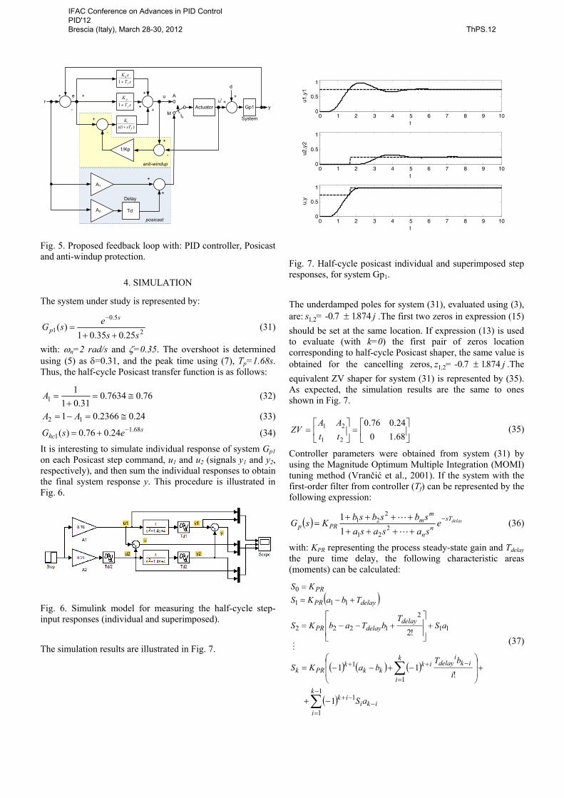
Fig. 5. Proposed feedback loop with: PID controller, Posicast and anti-windup protection.
4. SIMULATION
The system under study is represented by:
2
5.0
1 25.035.01)(
ssesG
s
p++
=−
(31)
with: ωn=2 rad/s and ζ=0.35. The overshoot is determined using (5) as δ=0.31, and the peak time using (7), Tp=1.68s. Thus, the half-cycle Posicast transfer function is as follows:
76.07634.031.01
11 ≅=
+=A (32)
24.02366.01 12 ≅=−= AA (33) s
hc esG 68.11 24.076.0)( −+= (34)
It is interesting to simulate individual response of system Gp1 on each Posicast step command, u1 and u2 (signals y1 and y2, respectively), and then sum the individual responses to obtain the final system response y. This procedure is illustrated in Fig. 6.
Fig. 6. Simulink model for measuring the half-cycle step-input responses (individual and superimposed).
The simulation results are illustrated in Fig. 7.
0 1 2 3 4 5 6 7 8 9 100
0.5
1
u1,y
1
t
0 1 2 3 4 5 6 7 8 9 100
0.5
1
u2,y
2
t
0 1 2 3 4 5 6 7 8 9 100
0.5
1
u,y
t
Fig. 7. Half-cycle posicast individual and superimposed step responses, for system Gp1.
The underdamped poles for system (31), evaluated using (3), are: j. .= -s , 87417021 ± .The first two zeros in expression (15) should be set at the same location. If expression (13) is used to evaluate (with k=0) the first pair of zeros location corresponding to half-cycle Posicast shaper, the same value is obtained for the cancelling zeros, j. .= -z , 87417021 ± .The equivalent ZV shaper for system (31) is represented by (35). As expected, the simulation results are the same to ones shown in Fig. 7.
⎥⎦
⎤⎢⎣
⎡=⎥
⎦
⎤⎢⎣
⎡=
68.1024.076.0
21
21
ttAA
ZV (35)
Controller parameters were obtained from system (31) by using the Magnitude Optimum Multiple Integration (MOMI) tuning method (Vrančić et al., 2001). If the system with the first-order filter from controller (Tf) can be represented by the following expression:
( ) delaysTn
n
mm
PRp esasasasbsbsbKsG −
++++++++
=L
L2
21
221
11 (36)
with: KPR representing the process steady-state gain and Tdelay the pure time delay, the following characteristic areas (moments) can be calculated:
( )
( ) ( ) ( )
( ) iki
k
i
ik
iki
delayk
i
ikkk
kPRk
delaydelayPR
delayPR
PR
aS
ibT
baKS
aST
bTabKS
TbaKSKS
−
−
=
−+
−
=
++
∑
∑
−+
+⎟⎟
⎠
⎞
⎜⎜
⎝
⎛−+−−=
+⎥⎥
⎦
⎤
⎢⎢
⎣
⎡+−−=
+−==
1
1
1
1
1
11
2
1222
111
0
1
!11
!2M
(37)
IFAC Conference on Advances in PID Control PID'12 Brescia (Italy), March 28-30, 2012 ThPS.12

The PID controller parameters can be expressed from the areas (37) in the following way (Vrančić et al., 2001):
⎥⎥⎥
⎦
⎤
⎢⎢⎢
⎣
⎡−
⎥⎥⎥
⎦
⎤
⎢⎢⎢
⎣
⎡
−−−−
−=
⎥⎥⎥
⎦
⎤
⎢⎢⎢
⎣
⎡−
00
5.00 1
345
123
01
SSSSSS
SS
KKK
d
p
i (38)
In our case, the process with the first-order controller filter with time constant Tf=0.1 is:
32
5.0
2
5.0
1*
025.0285.045.01
1.011
25.035.01)(
ssse
sssesG
s
s
p
+++=
=+++
=
−
−
(39)
Therefore, the areas (37) are the following:
0069.0 ,0969.0 ,1045.0 ,2675.0 ,95.0 ,1
543
210−=−=−=
===SSS
SSS (40)
and the controller parameters (38) are:
138.0 ,738.0 ,201.0 === dip KKK (41)
Fig. 8 shows the system response with filtered PID controller in the closed-loop configuration with the process. The tracking and disturbance-rejection performance is stable and relatively fast all according to the MOMI tuning method.
0 2 4 6 8 10 12 14 16 18 200
0.2
0.4
0.6
0.8
1
1.2
1.4
y(t)
t
Fig. 8. Step responses for PID control tuned with the areas method, for system Gp1.
However, the overshoot can be reduced and the tracking performance can be made better by using control scheme presented in Fig. 5, with settings defined in (34) and (41). Fig. 9 presents the system output response to a unit step input signal obtained with three control structures: the PID controller, the PID controller with the half-cycle Posicast (PID-P) and the PID controller with anti-windup protection and the half-cycle Posicast (PID-AW-P), using the control implementation presented in Fig. 5. The switching time equals settling time of the process. In this case the switch in Fig. 5 changes to automatic mode (PID closed-loop control) at t=4s. A step input disturbance with amplitude of 0.2 has
been applied to the process output at t=10s. Fig. 10 presents the control signals obtained in simulation.
0 5 10 15 20 25 300
0.2
0.4
0.6
0.8
1
1.2
1.4
t
y(t)
PID
PID-PPID-AW-P
Fig. 9. System output step response obtained with the PID controller, PID with half-cycle Posicast and the bumpless PID control configuration presented in Fig. 5.
0 5 10 15 20 25 300.4
0.5
0.6
0.7
0.8
0.9
1
1.1
1.2
1.3
1.4
t
u(t)
PID
PID-PPID-AW-P
Fig. 10. Control signal output for the step responses presented in Fig. 9.
As it can be seen from Fig. 10, there is a relatively large change of controller output signal when switching into automatic mode with PID-P controller. On the other hand, anti-windup protection was more than efficient when using PID-AW-P controller, since there was no large change of control signal. The results indicate that the proposed methodology clearly improve the set-point tracking performance of the underdamped control system due to the Posicast compensator, while maintaining the regulatory performance of the PID controller.
IFAC Conference on Advances in PID Control PID'12 Brescia (Italy), March 28-30, 2012 ThPS.12

6. CONCLUSIONS
A new technique was proposed which integrates the half-cycle shaper as a feedforward compensator to increase tracking performance and a PID controller to retain disturbance rejection properties. The transition between the manual feedforward set-point operation and automatic feedback PID control is accomplished by using an appropriate anti-windup and bumpless transfer technique. The proposed solution is especially efficient for decreasing the overshoots of underdamped second-order systems. Simulation results clearly indicate that the Posicast technique significantly improves the set-point tracking performance compared to the PID controller.
The proposed control structure can be easily implemented and has a great margin for improvement. The issue of model parameter uncertainty is to be addressed in future research.
REFERENCES
Araki M. and Taguchi H., (2003). Two-Degree-of-Freedom
PID Controllers. International Journal of Control Automation, and Systems Vol. 1, No. 4, pp. 401-411.
Åström K.J. and Hägglund T.,(1995). PID Controllers: Theory, Design and Tuning. ISA Publishers,Research Triangle Park, NC.
Bohn C. and Atherton D.P., (1995). An Analysis Package Comparing PID Anti-Windup Strategies. IEEE Control Systems, pp. 34-40.
Chiang Loh P., Gajanayake C. J., Vilathgamuwa D. M. and Blaabjerg F., (2008). Evaluation of Resonant Damping Techniques for Z-Source Current-Type Inverter. IEEE Transactions on Power Electronics, Vol. 23, No. 4, pp. 2035-2043.
Dhanda A. and Franklin G., (2005). Vibration Control via Pre-loading. American Control Conference, pp. 3574-3579.
Hanus, Kinnaert M. and Henrotte J. L., (1987). Conditioning technique, a general anti-windup and bumpless transfer method. Automatica, Vol.23, No. 6, pp. 729-739.
Hung, H. Y., (2007). Posicast Control Past and Present. IEEE Multidisciplinary Engineering Education Magazine, Vol. 2, Nº 1, pp. 7-11.
John R. Huey, Khalid L. Sorensen, William E. Singhose, (2008). Useful applications of closed-loop signal shaping controllers, Control Engineering Practice, Vol. 16, pp. 836–846.
Kalantar S. M. and Mousavi G., (2010), Posicast control within feedback structure for a DC–DC single ended primary inductor converter in renewable energy applications, Applied Energy 87 (2010) 3110–3114.
Kucera V. and Hromcik M., (2011), Delay-based input shapers in feedback interconnections, Preprints of the 18th IFAC World Congress, pp. 7577-7582.
Li Y.W., (2009), Control and Resonance Damping of Voltage-Source and Current-Source Converters with LC Filters. IEEE Transactions on Industrial Electronics. Vol. 56, Nº 5, pp. 1511-1521.
Peng Y., Vrancic D., and Hanus R., (1996), Anti-windup, Bumpless and Conditioned Transfer Techniques for PID Controllers, IEEE Control Systems, pp. 48-57.
Singer N.C. and Seering W. P. (1990). Preshaping command inputs to reduce system vibration, Journal of Dynamic Systems Measurement and Control, Vol. 112 (3), pp. 76-82.
Singh T. and Singhose W., (2002). Tutorial on Input Shaping/Time Delay Control of Maneuvering Flexible Structures, American Control Conference, Anchorage, AK, pp. 1717–1731.
Singhose W. and Seering W. (2005). Control of Flexible Manipulators with Input Shaping Techniques, in Flexible Robot Manipulators - Modelling, Simulation and Control, M. O. Tokhi and A. K. M. Azad, Eds. Stevenage, UK: Institution of Electrical Engineers.
Singhose, W. (2009). Command Shaping for Flexible Systems: A Review of the First 50 Years, Int. Journal of Precision Eng. and Manufacturing, Vol. 10, No. 4, pp. 153-168.
Smith O. J. M. (1957). Posicast Control of Damped Oscillatory Systems, Proc. IRE, Vol. 45, No. 9, pp. 1249-1255.
Sorensen K. L., Singhose W. and Dickerson S. (2007). A controller enabling precise positioning and sway reduction in bridge and gantry cranes, Control Engineering Practice 15, pp. 825–837.
Sugiki A. and Furuta K., (2006), Posicast Control Design for Parameter-Uncertain Plants, Proceedings of the 45th IEEE Conference on Decision & Control, 3192-3197.
Tallman G. H and Smith O. J. M., (1958). Analog Study of Dead-Beat Posicast Control, IRE Transactions on Automatic Control, Vol. AC-4, pp. 14-21.
Visioli A., (2006). Anti-windup Strategies, Practical PID Control Advances in Industrial Control, 2006, 35-60, Springer-Verlag, DOI: 10.1007/1-84628-586-0_3.
Vrančić D., Kristianssion B., Strmčnik S. and Oliveira P. M. (2005). Improving performance/activity ratio for PID controllers. IEEE International Conference on Control and Automation, Budapest, June 27-29, pp. 834-839.
Vrančić, D., Strmčnik S. and Juričić Đ. (2001). A magnitude optimum multiple integration method for filtered PID controller. Automatica. Vol. 37, pp. 1473-1479.
Walgama, K. S., Rönnbaöck, S., and Sternby, J. (1992). Generalizationof conditioning technique for anti-windup compensators, IEE Proceedings D, 139, pp. 109-118.
Yildiz Y., Annaswamy A., Kolmanovsky I. and Yanakiev D., Adaptive posicast controller for time-delay systems with relative degree n*≤2, (2010), Automatica 46, pp. 279-289.
Zaccariana L and Teelb A. R. (2002),A common framework for anti-windup, bumpless transfer and reliable designs, Automatica 38, pp. 1735-1744.
IFAC Conference on Advances in PID Control PID'12 Brescia (Italy), March 28-30, 2012 ThPS.12