Embed Size (px)
Citation preview

WWW.FUTUREAUTOMATION.NET
UBL EBF
TECHNICAL SHEETISSUE 014
SHEET 1
UNDER BED LIFT & END OF BED FLAP
UK +44 (0) 1438 833577 US +1 (603) 742 9181

SPECIFICATION MEASUREMENTSProduct Dimensions 1560mm (61.42") x 695mm (27.36") x 220mm (8.66")
Maximum Screen Size 1250mm (49.21") x 800mm (31.49") x 70mm (2.75")
Maximum Weight Capacity 40Kg (88lbs)
Minimum Height Required 320mm (12.59")
Minimum Length Required 1800mm (70.86")
Product Weight 85Kg (187lbs)
Packaging Dimensions 1700mm (66.92") x 1100 (43.30") x 500mm (19.68")
Shipping Weight 150Kg (331lbs)
Movement Type Motorised
Power Supply Required 110V - 240V AC
Power Consumption Max. 100W
Power Consumption Standby 1.5W
Mounting Patterns Supported VESA 400, 300, 200 W x 400, 300, 200 H
Control Options IR Remote, RS232
Product Options / Features Specific B&O and Loewe mounts / adapters, Custom RAL paint finishes, Marine suitable version
Package Contents Mechanism, IR remote control
Marine Suitable No
WWW.FUTUREAUTOMATION.NET
UBL EBF
TECHNICAL SHEETISSUE 014
SHEET 2
UNDER BED LIFT & END OF BED FLAP
UK +44 (0) 1438 833577 US +1 (603) 742 9181

X
X
Y
Y
Flap panel visiblewhen screenis hidden
Flap panel concealedunder bed whenscreen is revealed
Design HighlightsSophisticated electronics allow for favourite viewing height to be programmed via the IR remote control.
The electric flap retracts in under the bed. The Under Bed Lift (UBL) mechanism is then activated to reveal the screen.
This method of flap movement gives the neatest possible look as there is no flap panel left visible once the screen is in the viewing position.
Mechanism allows bottom of screen to be elevated up to 950mm [37.5"] above the floor.
All the power and signal cables for screen and mechanism can be concealed within the mechanism.
Super quiet and smooth action from under bed to maximum movement. Standard mechanism screen mount suitable for VESA 400x400, 400x300, 300x300, and 200x200 mounting.
An advance control system allows the lift mechanism to be easily controlled via home automation systems such as Crestron and AMX. Two way communication is also possible via RS232.
Many mounting options available forLoewe and Bang & Olufsen screens.
WWW.FUTUREAUTOMATION.NET
UBL EBF
TECHNICAL SHEETISSUE 014
SHEET 3
UNDER BED LIFT & END OF BED FLAP
UK +44 (0) 1438 833577 US +1 (603) 742 9181

0.820
Maximum FootBoard Thickness
10.0255
Opening height
52.81340Opening Width
Flap Panel Width = Opening Width -0.26
9.8250
Flap height
0.820
Maximum FlapPanel Thickness
UU
0.13
Flap attachment bracket
Flap panel material cannotbe thinner than surroundingfoot board material
Flap DetailsEnd of Bed Flap panel shouldbe made from wood.
Flap panel needs to bescrewed to flap attachmentsbrackets at each side.
Maximum flap panel weight6Kg [13lb].
WWW.FUTUREAUTOMATION.NET
UBL EBF
TECHNICAL SHEETISSUE 014
SHEET 4
UNDER BED LIFT & END OF BED FLAP
UK +44 (0) 1438 833577 US +1 (603) 742 9181

2.7570
10.5266
Minimum
1.128
Minimum
Space required at end of bed = Screen Height + 318mm [12.5"](Minimum 933 [36.75])
1.950
Suggested Clearancefrom Screen Topto Telescope Unit
3.179
End of Bed Space DetailsAt the end of the bed thereneeds to be enough space forthe mechanism to extend fromunder the bed.
There needs to be a minimum of'screen height + 12.5" / 318mm' atthe end of the bed.
If the screen is being biasedhigh on the screen mount toachieve even more elevation,then this end of bed space willneed to be increased.
WWW.FUTUREAUTOMATION.NET
UBL EBF
TECHNICAL SHEETISSUE 014
SHEET 5
UNDER BED LIFT & END OF BED FLAP
UK +44 (0) 1438 833577 US +1 (603) 742 9181

9.4238
14.7372
Lowest possible screen positiononce screen is hinged up
22.3566
MaximumTelescopicElevation
Telescope Elevation Details
WWW.FUTUREAUTOMATION.NET
UBL EBF
TECHNICAL SHEETISSUE 014
SHEET 6
UNDER BED LIFT & END OF BED FLAP
UK +44 (0) 1438 833577 US +1 (603) 742 9181
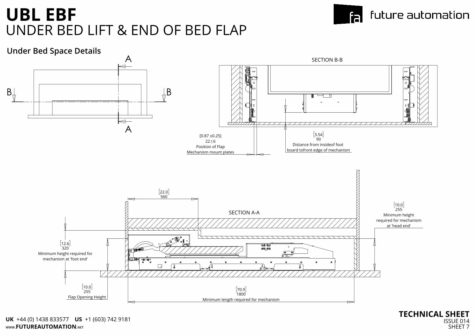
A
A
BB
22.0560
12.6320
Minimum height required formechanism at 'foot end'
10.0255
Flap Opening Height
10.0255
Minimum heightrequired for mechanism
at 'head end'
70.91800
Minimum length required for mechanism
SECTION A-A
[0.87 ±0.25]22 6
Position of FlapMechanism mount plates
3.5490
Distance from insideof foot board tofront edge of mechanism
SECTION B-BUnder Bed Space Details
WWW.FUTUREAUTOMATION.NET
UBL EBF
TECHNICAL SHEETISSUE 014
SHEET 7
UNDER BED LIFT & END OF BED FLAP
UK +44 (0) 1438 833577 US +1 (603) 742 9181

ADAD
59.11500
Mechanism Width
20.0508
6.0152
6.0152
20.0508
4.5114
41.31050
4.5114
61.01550
Minimum internal width needed
Fixing Location DetailsAreas outlined in red show areas where fixings need to be made to the floor below.
These areas should ideally be wooden surfaces so that the mechanism components can be screwed down in place.
For instances where the mechanism can't be atached to the floor a rear wall fixing can be provided
These areas also need access from above in order to get the fixings in place.
WWW.FUTUREAUTOMATION.NET
UBL EBF
TECHNICAL SHEETISSUE 014
SHEET 8
UNDER BED LIFT & END OF BED FLAP
UK +44 (0) 1438 833577 US +1 (603) 742 9181

3.282
Bottom Edge of Bracketto Bottom Edge of Flap
3.588
Top of Bracket to Flap Top Edge
2.769
Edge of Bracket toEdge of Flap
2.769
Edge of Bracket toEdge of Flap
3.282
Bottom Edge of Bracketto Bottom Edge of Flap
3.588
Top of Bracket to Flap Top Edge
A
0.00
3.795
4.8122
5.9150
0.
0 0
0.
75 19
2.
25 57
1.
538
3.897
5.8147
DETAIL A
Flap Fixing LocationsEdge of flap shown by red outline.
WWW.FUTUREAUTOMATION.NET
UBL EBF
TECHNICAL SHEETISSUE 014
SHEET 9
UNDER BED LIFT & END OF BED FLAP
UK +44 (0) 1438 833577 US +1 (603) 742 9181

P
P
Q
QCB
DETAIL B DETAIL C
EmergencyStop
RS232 Input
IR Input
Mains Input
Cable ManagmentDetail B shows the hole in which the end customers cabling will enter the mechanism after being passed through the cable management track.
Detail C shows the where the mains power, IR and ethernet cables will need to be inserted.
WWW.FUTUREAUTOMATION.NET
UBL EBF
TECHNICAL SHEETISSUE 014SHEET 10
UNDER BED LIFT & END OF BED FLAP
UK +44 (0) 1438 833577 US +1 (603) 742 9181


![Effect of Gurney Flap on Airfoil Lift Coefficient by Design of …jast.modares.ac.ir/article-15-20880-fa.pdf · of Gurney flap on SFYT15thick airfoil [19] Aerodynamic efficiency study](https://img.dokumen.tips/doc/110x75/60bd5a358e42e2274f7a1aaf/effect-of-gurney-flap-on-airfoil-lift-coefficient-by-design-of-jast-of-gurney-flap.jpg)


