Embed Size (px)
Citation preview

A-31
VALICHANGER OPERATIONS MANUAL
SERIES AC2225
American Changer Corp. Parts & Service:(888)741-98401400 NW 65th Place Sales:(800)741-9840Ft. Lauderdale, FL 33309 Fax:(954)917-5204
Internet Address: www.americanchanger.comService Questions? e-mail: [email protected]
Table of ContentsSECTION A: SET-UP & INSTALLATIONUncrating & Setup 3Mounting instructions 3-4Filling the Hopper 4Using the Dump Mode 4DIP Switches 4-5Fuses 5Functional Descriptions 5-6Indicator Lights 6Coin Control Hopper (Filling) 6Wiring definitions 6HOPPER ERROR CODES 7
SECTION B: VALIDATORINFORMATIONSetting 18-Pin Jumper Plug 7CoinCo Validator information 7-13Mars 2600 information 14-19
SECTION C: COIN HOPPERINFORMATION
Un-Jamming the Hopper 23-25
SECTION D: TROUBLESHOOTING INFORMATION Troubleshooting Guide 27Technical Flow Diagram 28-29
SECTION E: PARTS LISTSCabinet Parts Breakdown 30Parts Coin Control Hopper MKIV 31Parts CoinCo Bill Validator 32-35Parts Mars Bill Validator 36-38
SECTION F: SERVICE CENTERSCoinCo 39Mars (MEI) 40-42
Rev. MONO A-40 Jan.’04
Specifications
Operating voltage 120 VAC +10/-15 %Power consumpt.(controller only, add hopper and validator)10wOperating temperature 32 - 130 degrees FahrenheitInterface to Hoppers 24vdc & 12vdc 1.5 amps max.Interface to Validators 120vac .5 amps max.
WarrantyCoinCo MAGPRO 00 BAB & MARS AE2601 Validator is
warranted for two years from date of purchase.COVERED¥ Defect in workmanship or material.NOT COVERED¥ Damage caused by physical abuse.¥ Misapplication¥ Vandalism¥ End users attempt, on his own to repair item¥ Cleaning maintenance
It is the End User’s responsibility to follow cleaningmaintenance procedure outline on page(s) 12/18. Any unit
coming in for repair requiring only a cleaning will be chargeda flat rate of $65.00 plus shipping and handling.
Dispensing System and Logic BoardThe dispenser and logic board is warranted for one year from
date of purchase.COVERED¥ Defects caused by material or workmanship.NOT COVERED¥ Damage caused by physical abuse.¥ Misapplication¥ Vandalism¥ End Users attempt, on his own to repair.
A Return material authorization number (RMA #) must beobtained before returning a unit for repair. A copy ofinvoices must accompany any and all warrantee work

2
Attention Please:
To ensure the most trouble-free machine operation, we recommend plugging all our machines into aDEDICATED AC outlet. (This means there are no other machines on location plugged into the sameAC line.) A simple way to check if this is true is to turn off the breaker at the fuse box associatedwith our machine. No other machines on location should lose power or turn off.
American Changer is now building in a Surge Suppressor on every main logic board made afterSeptember 1st, 1998. This will help eliminate power related noise problems for our customers. Itwill not protect you from large voltage spikes or lightning strikes over 150VAC.
If this is a concern for your area of business, we recommend purchasing a surge protector locallyNOTE: A POWER STRIP IS NOT A SURGE PROTECTOR..
AC ___________ S/N# ___________________
Tested By ___________________________
Date __________________Thank You,
American Changer Corp.

3
UNCRATING AND SET-UP
Remove your Series AC2225 changer from the shipping box.Open the door. (The 2 T-handles are the screw-in type andtherefor, must be turned at least 10 times counter-clockwiseuntil it opens.) Inspect for any connectors or components thatmay have been dislodged during shipping. The matchinglocks and keys for your changer will be inside the manilaenvelope along with this manual. To install the locks, insertthe cylinders into the round hole in the middle of the T-handles and push until they stop. Now turn the key and lockuntil you hear it “snap." Turn the key counter-clockwise ¼turn and remove the keys.
TEST:Before permanently installing the changer, do a functional testto verify that there is no shipping damage to your newchanger(s).
Extend the power cord through the hole in the back of thechanger or the bottom and plug it into a grounded 120vacoutlet. The dip switches are already set for a 4 coin perdollar pay-out of the hopper, and the Bill validator isready to accept $1-$5-$10-$20 dollar bills.
Fill the hopper with at least 100 coins. On the main logicboard turn the switch on the bottom right corner “ON". (SEEFIG. 1 ON PG.3) The rocker switch has a “1” and “0”printed on it. When the “1” is pressed down the changer is“ON”.
MOUNTING THE AC2225 INTO A WALL
IF YOU ARE UNSURE IN ANY WAY IN PROCEEDINGWITH THE FOLLOWING STEPS, PLEASE HIRE ALOCAL PROFESSIONAL ELECTRICAN TO MOUNTYOUR CHANGER FOR YOU!
1. Disconnect any and all AC power going to the series1002 changer. (See fig. 1)A. Unplug the AC line cord from the bottom of the
board.B. Unplug the validator connectors on the right side of
the board.C. Unplug the hopper harness connector on the left side
of the board.D. Unbolt the ground wire from the right side of the
cabinet.E. Remove the main logic board and hopper from the
inside of the changer.F. Put the nuts back on the studs to avoid losing the
brass spacers on the studs.2. Slide the hopper out of the cabinet.3. Note: You will need to verify with the building that it is
allowable to plug the changer into a 3 prong groundedoutlet. If it is not, there must be 120VAC run through
conduit to the changer. If it is not required, proceed tostep #6.
4. Let the electrician run the conduit, install the newbreaker, wire and help decide how the wiring will enterthe changer (from the back or the bottom). This willaffect the mounting location.
5. After the conduit has been installed, proceed with themounting.
6. Using a stud locator, find a location to hang the changerby locating the wall studs.
7. Find an appropriate wall to bolt the changer into. Thewall should have studs or be constructed of concrete.Consult a professional with any questions you may have.
8. NOTE: SECURING THE CHANGER FROM LESSTHAN 4 BOLTS OR WELDED ANGLE IRON MAYBE DANGEROUS. EACH HOLE NEEDS A BOLTTHROUGH EACH ONE MOUNTED SECURELYINTO THE WALL. MOUNTING THE CHANGER INANY OTHER WAY MAY RESULT IN THECHANGER BEING TORN OFF OR FALLING OFFTHE WALL RESULTING IN PERSONAL ORCUSTOMER INJURY ALONG WITH ELECTRICALSHOCK.
9. Choose a height to mount the changer keeping in mindthat a handicapped person in a wheelchair should still beable to insert a bill into the bill validator. (Werecommend no higher than 4 feet above the ground.)
10. Have someone hold the changer into the wall whilesomeone else marks the holes. CAUTION: THECHANGER WEIGHS 85 POUNDS DO NOT EXERTYOURSELF SO THAT YOU MAY CAUSE ANINJURY.
11. BEFORE DRILLING THE FOUR MARKED HOLESENSURE THAT THERE ARE NO ELECTRICALWIRES, TELEPHONE LINES, GAS, OR WATERLINES BEHIND THE WALL WHICH DISRUPTINGMAY CAUSE A LOSS OF LIFE OR PERSONALINJURY!
12. Put the changer back into the wall. Thread and tightenbolts.
13. Verify that the machine is securely mounted. 14. Reinstall the main logic board.
A. Before installing the main logic board, verify thatthe plastic safety-insulating sheet is still against theback wall where the board will be mounted and thatthere is a 3/8” spacer on each stud.
B. Install the main logic board and properly tighten thenuts.
C. Re-bolt the ground wire into the right side of thecabinet.
D. Plug the validator connector into the right side ofthe board.
E. Plug the hopper harness connector into the left sideof the board
16. If the changer is permanently connected through aconduit, proceed to step #18.
17. Feed the AC line cord out the bottom or the back of thechanger then perform the following.A. Connect the AC line cord into the bottom of the main
logic board.
NOTE: The only way to get a duplicateset of keys made is to save the red tag
that comes between the keys.This ID # starts with “ACC ####”.

4
B. Plug the male end into the AC wall outlet. Do notuse an extension cord unless allowed by thebuilding electrical code.
C. Important: Attach the line cord clamp to the linecord. Verify it is at the right length and that the linecord is not rubbing against any sharp edges or isbeing strained in any way. Then mount the line cordclamp to the studs at the hole. Tighten securely.Installation is finished and you can proceed to the“Filling the Hopper” section.
18. In order to continue you will need to purchase electricalcable conduit, a standard 3-prong AC wall outlet and 12-gauge wire. We highly recommend HIRING a qualifiedelectrician to perform the following!
A. Install the conduit box on the conduit entering thecabinet in the lower right side of the cabinet.
B. Secure the 3 wires (hot, neutral, and ground) to theAC wall outlet and the ground wire should also bedirectly attached to the cabinet ground terminal.
C. Connect the AC line cord into the bottom of the mainlogic board.
D. Plug the male end into the AC outlet just installed.E. Properly fold the line cord to avoid sharp corners and
any other damage.19. Proceed to the “Filling the Hopper” section.
FILLING THE HOPPER (S)
When the hoppers have less than 80 - 100 coins left in it thered “Empty” LED will light on the front of the changer. Ifyou have disconnected your LED make sure the orange wire isgoing to the terminal on the LED that has the red positivemark next to it. Whenever the “Empty” LED is “ON” thevalidator is disabled and it will no longer accept bills.
1. Turn OFF the power on the main logic board.2. Pour the coins through the opening on the top. There
must be at least enough coins to cover the two goldplates at the bottom of the hopper. (Somewherebetween 160 and 12,000 coins minimum tomaximum.)
3. Turn “ON” the power switch. The “Empty” LED is nowoff and the bill validator is ready to accept bills.
USING THE DUMP MODE TO EMPTY THE HOPPER1. Open the cabinet door.2. Turn OFF the POWER switch.3. Place a suitable container in front of the hopper to catch
the coins.4. Press and hold the “DUMP” button on the upper left
corner of the Main Logic Board. Turn ON the Powerswitch. The red LED on the main logic board will comeon then go off. Once the red LED goes off, release the“DUMP” button. If it is not released within two seconds,the “DUMP” mode is canceled as a security feature. Thehopper will dispense coins until the POWER switch isturned OFF. If the Red LED on the Main Logic Board isnot flashing 3-5 times per second the dump mode was notaccessed. Please try again.
THE DIP SWITCHESThe AC2225 series changer is capable of dispensing from 0 to31 coins per dollar. Setting the coins out per dollar iscontrolled by which Dipswitches turned “ON." (Refer tofigure 1 for their location.) For example, switch #3 is “ON”;therefor the payout equals 4 coins per dollar.
FIGURE 2(THIS IS NOT THE DIPSWITCH BANK FOR SETTING
THE BILL DENOMINATIONS. (For those dip switches go to page 10-11.)
The following table shows how to set the dip switches to yourdesired payout.
“ON” COINS PER DOLLAR #1 1 #2 2 #3 4 #4 8 #5 16
If you want to dispense 10 dimes per dollar turn “ON”switches 2 and 4. (2 coins + 8 coins = 10 coins.) If you want to dispense 20 nickels per dollar turn “ON”switches 3 and 5. (4 coins + 16 coins = 20 coins.)DipSwitch #6 is for giving extra coins for every $5.00 billinput. This is for a token bonus mode payout. If you aregiving 4 coins per dollar, then 4 extra coins are given. If youare paying 5 tokens per dollar, 5 coins are given extra. This isthe only bonus mode available in the AC2225 series changer.
ON
1 2 3 4 5 6 7 8A-40
BILLMETER
ON/OFFSWITCH
EPROM CHIP
Figure
PRIMARY1-AMPFUSE
10
00001DUMP
BUTTON
TRANSFORMER
HOPPERSHARNESS
CONNECTORS
DIPSWITCH
ValidatorHarness
Connector.
AC LINECORD INPUT

5
EXAMPLE: With dipswitch #6 “ON” and a 4 coin per dollarpayout this will be the amount dispensed for each billdenomination.
$1.00 bill 4 coins $5.00 bill 24 coins$10.00 bill 48 coins$20.00 bill 96 coins
Dip switches 7 and 8 should remain in the “OFF” position.
FUSEHigh voltage fuse: This is the primary transformer AC fusefor the main logic board and the validator. Any direct short ofthe Transformer or validator will cause this fuse to blow.Replace this fuse with a 1-amp GDC fuse only. REPLACINGTHIS FUSE WITH ANYTHING OTHER THAN A 1- AMPMAY RESULT IN A FIRE OR AN UNSAFE WORKINGCONDITION!! (See fig. 1 for location of this fuse.)
Functional Description of the Series AC2225 ChangerTo follow along with this walk-through of your changer, fill
the hopper with coins and turn the changer on.
1. When power is applied the validator will cycle twice, theout-of-service LED flashes then goes out. The greenLED on the main logic board comes on steady, and thered LED on the main logic board will light then go offthen flicker on once per second in the standby mode.
2. During the power-up mode the main logic board relayclicks twice enabling power (120vac) to the validator.When this relay is not enabled it routes 12vdc ground tothe out-of-service LED. Without power to the validatorthe changer cannot accept bills. Since we are not in theerror mode, the red LED on the validator logic board ison steady.
3. When a bill is inserted into the validator bill slot, the billwill be pulled inside. The validator then compares whatthe bill looks like to its memory. After the bill isvalidated it grounds the 5vdc lines causing a pulse alongthe yellow and blue validator harness wires to pins 5 and6 of the main logic board. Each pulse stands for theamount of the denomination validated. (i.e. 1 pulse for$1, 5 pulses for $5).
4. The 5vdc pulse then travels from pins 5 and 6 to theEPROM chip (MONO A-40) EPROM sends a 12vdcpulse to the meter chip (U5) out pins #21 & 22 (one pulseper denomination validated). The EPROM also multipliesthe bill pulse by the DipSwitch settings (The EPROMreads the DipSwitch settings during the power up modeand stores them into memory.)
5. The EPROM then sends the hopper pulses out pin #23 topins 6 and 7 of the red 12-pin hopper plug. These pulsestravel through the purple and brown wires of the hopperwire harness to the hopper pins 8 and 12.
6. The hopper turns itself on with the first hopper pulse.The hopper counts the hopper pulses sent from theEPROM chip on IN3 (pin 12) while dispensing the coinsat the same time. When the amount of hopper pulses inequals the coins dispensed through the coin countingoptical sensor the hopper turns itself off.
7. The Changer returns to the standby mode with the redLED flashing once per second until another bill isinserted.
NOTE: THE METER ON THE MAIN LOGIC BOARDCANNOT BE RESET TO ZERO!!!
Functional Descriptions of Out-of-Service Conditions
Out-of-Service conditions occur for the Series AC2225changer for the following reasons; low coins, hopper fault
error, validator fault, or a blown fuse.
1. Blown Fuse: a AC power spike in line voltage or a badtransformer on the main logic board can cause A blownfuse on the main logic board. If either fuse blows theindication is the green LED on the main logic board willnot light.A. Replace the fuse. If the green LED now lights then
there was a spike. B. If it does not and the fuse blows again the power
transformer is shorted. To test the transformer use avoltmeter set for ohms and measure across theprimary (40-ohms) and the secondary (1.5-ohms).
2. Hopper Fault: A hopper fault can either be a jammedhopper, a blocked coin counting optic or a bad hopperlogic board. A. Indications for a jammed hopper are the changer
accepts bills, the meter counts up, but nothing ornot enough coins are paid out.
1. After 2 minutes the “Empty” LED on theoutside of the cabinet starts to blink once asecond and the validator is shut off.
2. At this point the three options open are toattempt repair on your own, call yourdistributor, or return the hopper toAmerican Changer.
B. Indications for a blocked coin optic or bad hopperlogic board are the out-of-service LED on theoutside of the changer is lit and the red LED on themain logic board is lit and flickers off once persecond.1. If two of the 3 green LED’s on hopper logic
board are lit then the hopper logic board isbad.
2. If there is a coin or foreign object caught inthe coin exit window LED’s #1 and #3 willbe lit on the hopper logic board instead ofLED’s #1 and #2. a. Take off the side of the hopper with 5
Philips screws. Pull up on the exitwindow logic board and look for thejammed item.
b. Ensure you have the pins aligned beforereconnecting logic board.
3. Validator Fault: When a validator fault occurs thevalidator’s EPROM shuts down the validator and flashesan error code via the red LED on the validator logicboard. When there is no error this LED is on steady. Thevalidator only gives bill pulses to the main logic board sothe main board never knows if the validator isn’t

6
functioning. Therefore the out-of-service-LED will notlight. (See page 6 for validator error codes.)
4. Low Coins: The low coin condition is probably the mostcommon fault. The EPROM on the main logic board isconstantly checking for low coins in the hopper. This isdone with a low current 5vdc signal on pin #3 of thehopper output connector. The voltage then travels downthe hopper wire harness on the white wire to pin #7 ofhopper plug. The signal is applied to one of the gold lowcontact plates at the bottom of the hopper. The 5v travelsthrough the coins through the other contact gold plate tohopper pin #2. It then goes through the black wire in thehopper harness to pin #10 on the main logic board. Anyinterruption of more than 1/2 a second will cause an out-of-service condition.A. Clean the bottom gold plates of the hopper with
steel wool or a fine sandpaper. Refill the hopperand try again.
B. Check continuity, (0 ohms) resistance, from pins 3(white) and 10 (black) of the red hopper harness.Make sure the hopper full and the changer turnedoff.1. If the continuity is 0 ohms, replace the main
logic board.C. Pull the hopper out of the changer, then look at the
12 pin black male connector that sticks out of thehopper. Place the continuity checker’s leads onpins 2 & 7.1. If the continuity is 0 ohms, replace the hopper
plate or adjust the hopper plate’s femalesocket’s pins so that they are not so spread out.
2. If the continuity is infinity, then replace thehopper.
Indicator LightsMain Logic Board:1. Green LED on: AC power applied to the logic
board. All fuses are good.
Validator logic board:1. Red LED
A. On Steady - Standby Mode, waiting for billinsertion.
B. Flashing - Error mode, go to page for error codeinformation.
C. Off - The changer “Empty” LED is lit.
WIRE HARNESS COLOR AND DEFINITIONS
Validator harness:Red - Switched Hot 120VAC.White - Neutral 120VAC.Black - 120VAC Low current validator enable.Yellow - +5vdc credit pulse line.Blue - -5vdc credit pulse line.Orange - +12vdc Empty LED.Brown - -12vdc Empty LED.
Hopper HarnessGray - Coin counting optic status line.White - Low coin sense (+5vdc).Green - Coin counting optic pay out feedback line.Yellow - Raw sensor output line.
Purple - Hopper pay out line from main logic board (+),Brown - Hopper pay out line from main logic board (-).Red - +12vdc logic board supply voltage.Black(s) -12v, 24v low coin sense ground.Orange - +24vdc Motor supply voltage.
Coin Control Hopper MKIVThree green LED indicators are fitted on the hopper and arevisible in the section where the coins exit the hopper. Fromleft to right these are designated as follows:1. Logic power supply on (12 & 24vdc present).2. Security optical obstruction indicator -. Should be ”on”
when unit is OK.3. Output indicator, indicates coin passing photo-sensor.
This is the optical sensor the coin will obstruct on its wayout of the hopper. For normal operation LED # 3 will beoff until coins are dispensed.
Coin/Token SizesThe hopper will automatically adjust to dispense coins/tokensin size from 20-30 mm in diameter and 1.25 - 3.5 mm inthickness.
There is an option available to dispense smaller coins.
A nickel is approximately 21 mm, a quarter is approximately25mm. A Susan B. Anthony is 28mm
12 pin maleconnector.
(located on theopposite side.)
Motor
Coin counting optic.
12vdc Power LED.
Security LED.(all systems OK)
Coin countingLED.
Hopper coinbin. (Dump
the coins intothis hole.
1600 coinsmax.)

7
HOPPER ERROR CODES
With the digital display the logic board is now able to conveyexactly why the “Empty” LED is lit. Press the “Dump”button while the “Empty” LED is lit. On the Light-updisplay the meter count will go away while holding the buttondown. These are the error code definitions:
1---- – Hopper was shut down completely.
-2--- - Hopper Exit Window LED is blocked.
--3-- - Low Coin Failure.
-23-- - Hopper is not Plugged into the Hopper Harness.
---4- - Hopper is Jammed.
----5 – Hopper Overpaid 2 Coins and was shut down.
Refer to the Troubleshooting section of this manual to repairthese failures.
VALIDATOR INTERFACES 18 PIN INTERFACE CONNECTOR DETAILS
PLUG KEY
Interfacing the Mars 2501 Series with the ValiChanger8-Position Switch1 off2 on3 off4 on5 off6 on7 off8 offNo change is required to the 18-pin connector..Ensure the black & yellow wires go to a wire nut and thegreen & white go to the other wire nut
Interfacing the Mars 2601 Series with the ValiChanger8-Position Switch1 on2 on3 on4 on5 off6 on7 off8 offThe 18-Pin interface connector is not needed.
CoinCo MAG Series Flash CodesFlash codes 1-18 may appear during normal servicing of theBA30. If more than one error or condition exists, the lowernumber flash code will appear until its respective error orcondition is corrected. The left and right sensors referencedbelow are given viewing the BA30 from the front.# of Flashes Description of Flash Codes1 Bill box full2 N/A3 Check bill path4 All bill accept switches are off5 Bill jam or sensor error6 Stacker motor/home sensor7 Transport motor/encoder sensor8 N/A9 EPROM Has Failed10 EPROM Has Failed11 Center Optic Failed12 Right Optic Failed13 Left Optic Failed14 Bill Position Sensor Error15 Right Bill Position Sensor Error16 Left Bill Position Sensor Error17 Lower Anti-Stringing Armature out of place18 Upper Anti-Stringing Armature out of place
1 2 3 4 5Press & hold“Dump” button
Pin #1Pin #9
Pin #18Pin #10

8
COINCO MAG50BVALIDATOR
SECTION PAGE
Removing the Bill Box 9
Clearing a bill jam 9
Setting the bill types accepted 10-11
Cleaning the sensors 11-12
Cleaning a salted unit 12
Replacing the belts 13

9
Removing the bill box.To remove the 1000 bill stacker from the CoinCo validator follow the picture below.
REMOVING A BILL JAM
From time to time a foreign object or ripped bill will become caught in the validator. Follow thepicture below to remove the item.

10
SETTING THE BILL ACCEPT DIP SWITCHES

11
CLEANING THE BILL VALIDATOR
Refer to the pictures and the procedure on the next page to clean the bill validator every 4-6months.
12
MAGPRO CLEANING: IF ANY OF THESE PROCEDURES ARE PERFORMED TO YOUR VALIDATOR AFTER IT ISRETURNED UNDER A WARRANTY REPLACEMENT, YOU WILL BE SUBJECTED TO A $65.00 LABOR FEE.
CLEANING AND MAINTENANCE:Note: Petroleum-based cleaners and freon-based propellants can damage plastic and some electronic components.Scouring pads and stiff brushes may harm the protective conformal coating on the circuit boards and can mar theplastic. These items should never be used when cleaning the MAGPRO bill acceptor.
The MAGPRO should be cleaned every 7,000bills or every 4 -6 months (or as needed,depending on the environmental conditions ofthe location). Dust can be removed with a softbrush or cloth or it can be blown out usingcompressed air.Procedure:1. Disconnect power from the bill acceptor.2. Remove the bill box and use a soft cloth to wipethe dust from around the intermediate frame andstacker plate.3. Remove the lower track.4. Using compressed air or a soft brush, blow orbrush the dust off of the optic sensors and out ofthe recessed sensor openings.5. Remove dust from around the belts and wheelson the lower housing and the sensors on the uppersensor board. The upper sensors are locateddirectly above the lower housing sensor when thelower housing is installed.6. The bill path can be cleaned to remove furtherdirt and oil using a soft cloth moistened with a mildsoap and water solution.7. Clean the magnetic head using a swab andisopropyl alcohol.8. Once the lower housing is dry, place it back intothe mainframe so that the tab on the bottom locksinto place.9. Blow the dust out of the encoder wheel and itssensors. (It may be necessary to extend thestacker plate to access the encoder wheel.Supplying power to the unit momentarily can dothis, so that the stacker plate extends.)10. Remove dust from the transport belt areas andfrom any other places of build up.11. Remount the bill box.12. Apply power and insert bills to verify that theunit is functions property.
MAGPRO CLEANING PROCEDURE FOR SALTWATER POLLUTED UNITS:Note: Petroleum-based cleaners and freon-basedpropellants can damage plastic and some electroniccomponents. Scouring pads and stiff brushes mayharm the protective conformal coating on thecircuit boards and can mar the plastic. These itemsshould never be used when cleaning the BA30 billacceptor.Procedure:1. Remove power from the bill acceptor.2. Remove the bill acceptor from the vending
machine.3. Open the bill box lid and verify that the stacker
plate is in the stand-by/home position. If it isnot in the home position, apply power andobserve that the stacker plate returns home.
Warning: If moisture is present, allow the unit todry thoroughly before applying power to avoidpossible shock hazard. If the stacker plate does notreturn to the home position, remove power andcarefully remove the bill box to avoid damaging thebill box and/or stacker plate.
4. Remove the lower housing.5. Remove the bottom cover from the lower
housing.6. Run hot water (1101/4-1401/4F) over the
lower housing from the top and bottom. Usinga soft brush, gently clean any residual salt. Usea soft absorbent cloth to clean any residue offthe lower housing. If the transformer gets wet,allow the unit to dry for 24 hours beforeapplying power.
7. Remove the front mask. Using hot water and asoft brush, clean the front mask, upper sensorboard, main frame anti-pullback levers andposition sensor mount.
Caution: The motors are not protected from water,therefore the unit must be held in a manner thatprevents water from running over the intermediateframe crossbar.8. Remove the position sensor cover on thecrossbar and carefully lift the LED from its mount.(Early models only.)Caution: Protective coating on the LED leads shouldnot be damaged. Clean all salt residue from themount, sensor hole and detector area.The detector can be seen through the sensor hole,and is located in the chassis. Replace the positionsensor cover. (Early models only.)9. Verify that the anti-pullback levers move freely
and that the spring returns them to their openposition.
10. Allow the unit to dry thoroughly.11. Clean the magnetic head using a swab and
isopropyl alcohol.12. Replace the front mask13. Replace the lower housing cover.14. Replace the lower housing into the main frame.15. Remount the bill box.16. Apply power and insert bills to verify that the
unit is functioning properly.6 OR 7 ERROR CODE FLASHESThe cleaning procedure for this common occurrenceis listed below. Just follow these steps. 1. If this code has occurred on a new machine or
one that the validators DIP switches were justchanged, Ensure that all the white plugs on theside of the validator board away from the redLED are plugged in securely.
2. Remove the bill box.3. Turn the Changer ON then OFF in an attempt
to stop the metal push plate so that it COASTSinto the fully outward position.
4. Using an air compressor or a can ofcompressed air blow out the area behind thepush plate until it is completely free of all dustand lint.
5. Turn the changer power back on so that thepush plate returns to the inward position. Ifthe same error code persists, repeat steps 1 -3 concentrating on the top center area behindthe plate.
2. Replace the bill box.

13
6. REPLACING THE BELTS
Every 2-3 years the belts on the CoinCo will wear out. To replace them, remove the validatorcomponents down to the picture show. Refer to the parts diagram at the end of the manualfor help getting to this point.

14
MARS AE2601
BILL ACCEPTOR120VAC $1-$20
MEI MARS AE2601VALIDATOR
SECTION PAGE
Removing the Bill Box 15
Clearing a bill jam 15
Setting the bill types accepted 16
Coupon Programming (Dip Switch) 17
Cleaning the Validator 18
Trouble Shooting & Trouble Codes 19

15
Removing the bill box
Clearing A Bill Jam
1. Pull up on silverbar (Rod)
2. Pull bar awayfrom the Mars.
1. Pushbill boxup andout.
2. PushBLUEbuttonforward.

16

17
Coupon ConfigurationThe AE2601 may be configured using a coupon.The coupon is included in the AE2601 SeriesInstallation Guide. Carefully cut the couponalongthe dotted-line edge to remove it from theinstallation guide. Copies of the original couponmay be produced with a standard, carbon-based,non-color copier. Cut copies to match the size ofthe original coupon.All option switches must be in the OFFposition for the coupon selections to beactive.The coupon selection will remain with theAE2601 until the unit is reprogrammed, even ifpower is removed.When filling out the coupon, note the following:Use only a #2 pencil to fill in the blocksFill in the entire blockDo not mark the coupon outside the blocksor on the back of the couponFill in ONE block for EVERY line
Coupon Programming1. Fill out the coupon using the table below. 2. Locate the service button on the back of theunit (refer to Figure 2).3. Press the button once to enter the couponsetup mode. Pressing again will exit themode. The unit will automatically exit couponsetup mode upon acceptance of thecoupon configuration.The LED Status indicator (located to the left ofthe service button) will flash rapidlyindicating that the unit is in coupon setup mode.4. Insert the coupon marked-side up.The AE2601 will pull the coupon in, read it, andthen return it to the user.A good coupon will be returned immediately.After the coupon is pulled from the billacceptor mouth, the unit will flash the StatusLED ten times to confirm a goodconfiguration.A bad coupon will be held for ten seconds beforebeing returned. This delay is tomake you aware that there is a problem withthe coupon. When the coupon is pulledfrom the bill acceptor mouth, the unit will flashthe Status LED the number of timescorresponding to the section of the couponwherein a problem lies. For example, if
THIS IS NOT A USABLE COUPON!
DO NOT COPY!!!FIGURE 1
FIGURE 2the problem is in section five, the LED willflash five times. Section numbers arelocated to the far right of each section on thecoupon.5. If the configuration is rejected, check thecoupon and repeat the process.

18
CleaningYou can clean the bill acceptor while it is still mounted in the machine (refer to Figure 3below).1. Remove power from the machine.2. Unlatch the magazine by pushing the blue latch (located on the top of the unit) towardthe front of the unit.3. Unhook and remove the magazine by holding the latch and lifting up and then back onthe magazine.4. Unlatch the LED Housing by lifting up on the metal bar (located below the Status LED).5. Remove the LED Housing by holding the metal bar and pulling back on the LEDHousing.6. Clean the bill path with a soft cloth. You may use mild, non-abrasive, non-petroleumbased cleaners if sprayed on the cloth.
FIGURE 3

19
Status LEDA Status LED provides assistance in diagnosing the condition of the Series AE2601. Thefollowing is a description of the LED codes, their meanings, and suggested remedial actions.

20
MKIV UNIVERSALHOPPER
SERVICE MANUAL
INDEX1. Coin box removal & reassemble. 21-23
2. Exit window replacement. 22
3. Logic board replacement. 23
4. End plate removal. 23
5. Track plate removal. 24
5a. Track plate assembly. 24
5b. Track plate replacement. 25
5c. Final drive gear replacement. 25
6. Gearbox assembly 26
7. Motor replacement. 26
To un-jam the hopper, performsections 4 thru 5b, pages 23-25.
PAGE

21
1. COIN BOX REMOVAL
1. Place the hopper in front of you as shown, (looking atthe outside of the ‘coin box’).
Refer to FIG 1.
2. Remove the 2 locking nuts, which hold the ‘low levelsense plate’ wires to the studs.
3. Remove the crimp & wire from the studs.
Refer to FIG 1a.
4. Remove the 5 screws indicated (B), which hold the‘coin box’ to the ‘center plate’.
Refer to FIG 1b.
6. Gently lift the ‘coin box’ away from the rest of thehopper.
NOTE:- The ‘logic board’ & ‘stirrer’ arelocated in the ‘coin box’.
7. As the ‘coin box’ is being removed, carefully slide the‘logic board’ out. The stirrer may stay with the ‘coinbox’ or fall onto the center plate.
ACCESS IS NOW AVAILABLE TO THE ‘LOWLEVEL’ SENSE PLATES, THE MAIN PCB, THEEXIT WINDOW, THE MOTOR TERMINALS &
PART OF THE WIRING LOOM.
1a. COIN BOX ASSEMBLY 1. Firstly, locate the ‘stirrer in the ‘coin box as shown in
FIG 12.

22
COIN BOX ASSEMBLY (cont.)
2. Line up the ‘centre plate’ & ‘coin box’ as shownbelow. FIG 12a.
3. Route the ribbon cable as shown below.
4. Fit the ‘logic board’ into slots shown below.
5. Feed the level sense wires through the slot shownbelow.
6. Lift the ‘centre plate’ to meet the ‘coin box’. FIG 12b& c.
7. Align the ‘center plate’ & ‘coin box’ & push together.
8. Turn the hopper over & refit the screws.
9. Refit the level sense wires.
2. EXIT WINDOW REPLACEMENT
1. First, remove the ‘coin box’, section 1.This will then enable access to the ‘exit window’2. Unscrew & remove the 2 fixing screws. FIG 4.3. Remove the ‘exit window’ from the ‘center plate’.4. Unclip & remove the 10-way ribbon cable header.
5. To re-assemble, follow the above steps in reverse.

23
3. LOGIC BOARD REPLACEMENT
1. First, remove the ‘coin box’, section 1.
This will then enable access to the ‘logic board’.
10-way ribbon IDC socket (CONN 1).
2. Move the two ejector arms at right angles to & awayfrom the connector, if fitted.
3. This should release the socket from the header.4. Clasping the connector between thumb & forefinger,
pull away from pin header.14-way crimp socket (CONN 2).
5. Gently, unclip the “friction lock” from the connectorhousing.
6. Clasping the connector between thumb & forefinger,pull away from pin header.
7. The Logic Board is now released.8. To re-assemble, follow the above steps in reverse.
4. END PLATE REMOVAL1. Place the hopper in front of you as shown, (looking at
the outside of the ‘end plate’).
Refer to FIG 6.
2. Remove the 9 screws indicated (B), which hold the‘end plate’ to the ‘center plate’.
3. Locate the position of the ‘connector blanking piece’.
4. Holding the ‘connector blanking plate’ gently lift the‘end plate’ away from the rest of the hopper.
5. To re-assemble, follow the above steps in reverse.
5. TRACK PLATE REMOVAL
1. 1. First, remove the ‘end plate’, section 6.
See FIG 7.
2. The ‘elevator track’ & ‘final drive gear’ can now beremoved by lifting up & away from the ‘center plate’.
24
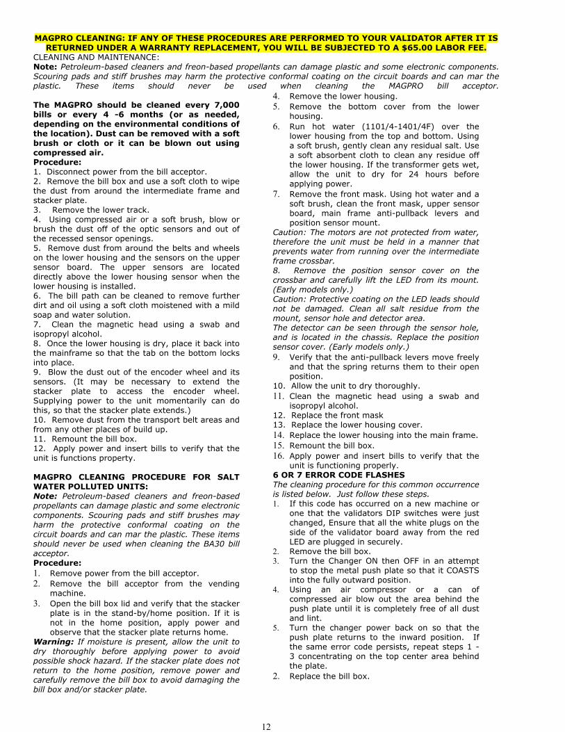
5a. TRACK PLATE ASSEMBLY
The following 3 sketches show how to take the ‘track plate’ apart.
The following 3 sketches show how to assemble the ‘track plate’.

25
5b. TRACK PLATE REPLACEMENT1. The gray shaded area, in FIG 7b, is the ‘track plate’ guide path.
FIG 7b.
2. Once the ‘track plate’ is in position, turn the track through 720 0 to ensure it is seated in the guide path correctly.
5c. FINAL DRIVE GEAR REPLACEMENT1. Once the ‘elevator track’ is in place, the ‘final drive gear’ can be fitted by placing the gear over its mounting spindle,
while lining the teeth up with the secondary drive gear, adjust the ‘elevator track’ so that the gear falls into place.FIG 7c.
3. The end plate can now be re-fitted. See section 6.
26
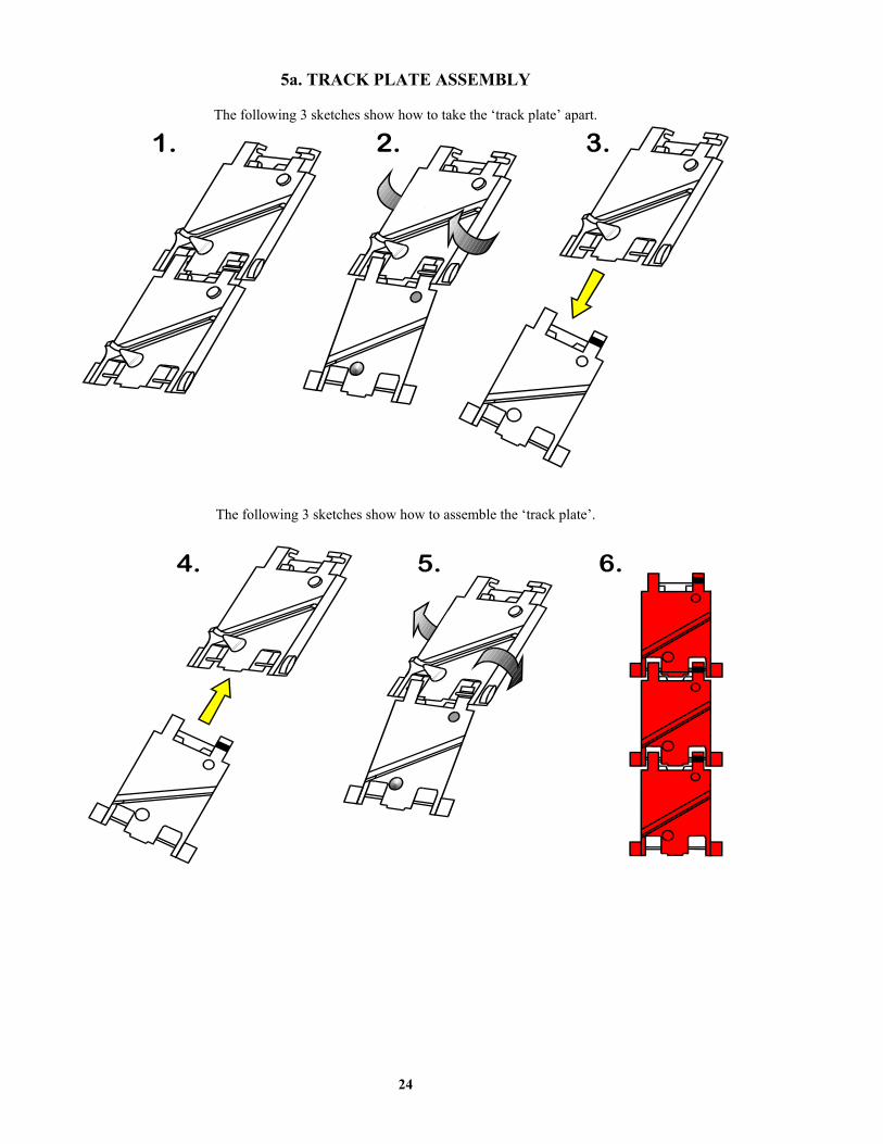
6. GEAR BOX ASSEMBLY
1. Remove the end plate. Section 6.
2. Remove the ‘elevator track’ & ‘final drive gear’.Section 7.
3. Remove the gearbox cover. Section 8.
4. Remove the gears in the order as shown in FIG 9.
Access to the motor fixing screws is now possible.
5. To re-assemble, follow the above steps in reverse.
7. MOTOR REPLACEMENT
1. Remove the ‘coin box’. Section 1.
2. Unsolder the red & black wires from the motor.
NOTE: The black wire connects to the terminalmarked with a RED dot.
3. Remove the ‘end plate’. Section 6.
4. Remove the ‘track plate’ & final drive gear. Section7.
5. Remove the gearbox cover. Section 8.
6. Disassemble the gearbox. Section 9.
7. Unscrew the 2 motor fixing screws. FIG 10.
8. To re-assemble, follow the above steps in reverse.

27
NOTE: Before starting this procedure ensure the changer is plugged in, the ON/OFF switch is on,the hopper is full of coins, and all wire harnesses are connected securely and correctly.
The wires exiting the red connectors should point away from the board!!Start Here!
For a more detailed trouble shooting information proceed to the next section!FOR TECHNICAL SERVICE OR TO OBTAIN A RETURN AUTHORIZATION NUMBER
CALL (888) 741-9840ANY REPAIR RETURNED WITHOUT A RETURN AUTH. # WILL BE REFUSED!!
IS THE"EMPTY" LED
"ON"?Yes
PRESS AND HOLD THE"DUMP BUTTON " ON
THE MAIN LOGICBOARD. WHAT
NUMBER(S) AREDISPLAYED?#1
#2 #3
#4
#5
HOPPER IS SHUTDOWN.
Hopper Exit windowis blocked. Pleasedo the following.1. Remove all thecoins.2. Take off theTrack side cover ofthe hopper.3. Remove theobject from thewindow.4. Reassemble thehopper.
The hopper has alow coin shut down.Please do thefollowing:1. Ensure thehopper is full ofcoins. Turn off themachine, wait 5 sec.then turn it back onagain.2 Clean the 3 goldplates at the bottomof the hopper wherethe coins are pouredin with a scotchbright pad or emerycloth.3. Check continuityof the wires fromthe gold plates backto the logic board.
The hopper isjammed.
The hopperoverpaid by 2to many coinsand was shutdown. Replacethe hopper orthe hopperharness.
NO
Is the GREENLED on themain logicboard on?
Yes
NO
Is the On/Off (I/O)
switch on?(I pressed
down?)
Yes
Is the120VAC plugpushed into
the bottom ofthe logic
board and intothe wall?
Yes
Using ameter checkthe 1-ampfuse. Is it
good good?
Yes
NO
Check the 120VACwall breaker.
Replace the logicboard.
Will the CoinCo billacceptor attempt topull bills in at all?
Are the RED billmeter numbers liton the main logic
display?
NOYes
NO
YES
It appears as if your CoinCo isdirty or the belts are worn. Pleasetry the following:1. Go to Page 7 and perform thecleaning procedure.2. If that is unsuccessful inspectthe plastic lower housing for deepscratches or VANDALISM.3. If the CoinCo has accepted over50,000 bills it could need newbelts.
The CoinCo isflashing an
"ERROR CODE".Please go to the
CoinCo Error codesection of this
manual. Page 8.
TECHNICAL FLOW DIAGRAM AC2225

28
Problem: A. The changer is completely
dead. (The green LED on themain logic board is not lit.)
B. The “Empty LED is lit.When the red LED on themain logic board is observed,the LED is flickering onbriefly once per second.
C. The “Empty LED is lit.
When the red LED on themain logic board is observed,the LED is on Steady.
D. The green LED on the mainlogic board is lit but the redLED never lights.
E. The bill validator accepts andstacks the money but the billmeter never counts up.
F. The bill validator stacks thebills, the meter counts up, butthe hopper does not pay out.
G. Bill validator will not pull in
the bill and the “Empty” LEDis not lit.
Solution:
1. Ensure the changer is plugged in.2. Ensure the on/off switch is rocked to the (1) position (down).3. Unplug the female end of the line cord from the main logic board AC
connector and plug it in again tightly.4. Measure the AC voltage at the outlet or check the breaker/fuse box.
You can also plug another item into the AC wall outlet to ensurethere is power present at the outlet.
5. Inspect the AC line cord for cuts or abrasions.6. Check both fuses on the Main Logic Board.7. Replace the main logic board.8. Replace the line cord.
1. Ensure the hopper is not out of coins. (There should be enoughcoins in the hopper to cover the gold low-level contact plates.These plates are located at the bottom of the hopper where you pourthe coins.)
2. Check the hopper wire harness that extends from the back of theplate that the hopper slides in and out on for chipped pieces or otherdamage. (Pay close attention to pins # 2 & 7.)
3. Clean the gold contact plates with steel wool.4. Replace the hopper.5. Replace the hopper wire harness.
1. Ensure the hopper is pushed into the hopper harness on the back ofhopper plate tightly.
2. Ensure that left and center green hopper LED’s are lit only. Not theleft and right LED’s. If this is the case go to pg. 19 to unjam thehopper exit window.
3. Replace the hopper.4. Replace the hopper plate.
1. Bad 5 or 12vdc regulator on the main logic board.2. The hopper is shorted.3. Replace main logic board.4. Replace hopper.
1. Check continuity and for pin damage to the blue and yellow wires onthe validator harness.
2. Replace the validator wire harness.3. Replace the validator.
1. Ensure the dip switch settings are still correct. (#3 “ON” only)2. Check the continuity of the brown and purple wires on the hopper wire
harness.3. The hopper is jammed. Go to pg. To unjam the hopper.4. Replace the hopper wire harness.
1. Ensure the orange wire going to the “Empty” LED is connected tothe + or the terminal with the red mark by it.
2. Check for 12vdc going to the orange and brown wires. If there is,replace the LED.
3. Replace the main logic board.4. Replace the bill validator.5. Replace the validator wire harness.
TROUBLESHOOTING GUIDETO USE THE TROUBLESHOOTING GUIDE, MATCH UP THE PROBLEM, THEN FOLLOW THE SOLUTION
SUGGESTIONS. After every step re-try operating the changer to see if the problem has been solved.

29
PROBLEM: H. The bill validator pulls in the
bill slightly then rejects it.
I. The bill validator red status
LED flashes a “5” error code.
J. The bill validator red statusLED flashes a “6 or 7” errorcode.
K. The bill validators red status
LED is on steady but it stillwill not accept the bill.
L. The red “empty” LED on the
outside of the changer is on,the red status LED on themain logic board is flickeringon and off normally, and thehopper is full of coins.
M. The “Empty” LED on theoutside of the changer isflashing once per second.
FOR TECHNICAL SERVICE ORTO OBTAIN A RETURN
AUTHORIZATION NUMBERCALL (888) 741-9840
SOLUTION:
1. Clean the validator. (pg. 9)2. Remove the lower housing (pg. 11) of the bill validator. Ensure the
center wheel spins freely. Push straight down on it slightly to loosen. 1. Clean the validator optic LED’s. (See pg. 9)2. Ensure that all the wire harness plugs are plugged firmly into their
white female sockets.3. Turn to the back page of this manual and check for a Coin Acceptors
branch in your area to repair your bill validator .
1. Take the bill stacker off the bill validator. Cycle the power on / offusing the switch on the main logic board and coast the silver push barso that it stops in its fully extended position. Blow out the area behindthe push bar with high pressure or canned air. Concentrate on theencoder wheel in the area top center behind the push bar.
2. Turn to the back page of this manual and check for a Coin Acceptorsbranch in your area to repair your bill validator.
1. Pull out the lower housing, see page , and look for somethingobstructing the bill path. (i.e. gum, paper, tickets, coins, etc.)
2. Look inside the Plexiglas case on the side of the bill validator. Ensurethat all the wire harness plugs are plugged firmly into their whitefemale sockets.
1. Ensure the hopper is not out of coins. (There should be enough coins inthe hopper to cover the gold low-level contact plates. These plates arelocated at the bottom of the hopper where you pour the coins.)
2. Check the hopper wire harness that extends from the back of the platethat the hopper slides in and out on for chipped pieces or other damage.(Pay close attention to pins # 2 & 7.)
3. Clean the gold contact plates with steel wool.4. Replace the hopper.5. Replace the hopper wire harness.
1. The hopper is jammed.2. The hopper failed to pay out what it was told.3. Service the hopper. (Pg. 21-24)4. Replace the hopper plate and harness.
ANY REPAIR RETURNED WITHOUT A RETURNAUTH. # WILL BE REFUSED!!
TROUBLESHOOTING GUIDETO USE THE TROUBLESHOOTING GUIDE, MATCH UP THE PROBLEM, THEN FOLLOW THE SOLUTION
SUGGESTIONS. After every step re-try operating the changer to see if the problem has been solved.

30
PARTS LIST FOR THE AC2225
AC2225 PARTS LIST(SHOWN ABOVE)
1. AC2013 -CABINET COMPLETE W/ COIN CUP (#2) & LOCK BRACKET (#3).2. AC1010-01 -COIN CUP3. AC1011-20 -LOCK BRACKET ASSY. COMPLETE.4. AC1040.1 -COIN CONTROLS MKIV COIN HOPPER.5. AC1040.4 -COIN CONTROLS HOPPER PLATE W/ FEMALE PLUG & HARNESS.6. AC1061 -MAIN LOGIC BOARD.7. AC1085 -FULL FACE LEXAN FRONT.8. AC5080 -SCREW-IN T-HANDLE.9. AC9001.1 -COINCO BILL VALIDATOR.10. 1906 - MANUAL PACKET
AC2225 OPTIONAL PARTS LIST(ITEMS NOT SHOWN.)
AC2013.1 -STAINLESS STEEL FRONT PLATE (LEXAN NOT INCLUDED)AC2085 -FULL FACE LEXAN FRONT.AC2013-01 -HOPPER EXTENSION (8800 COINS)AC1043.1 -650 BILL STACKERAC1044 -1000 BILL STACKERAC1093 -LOCK AND KEYAC1095 -MEDICO LOCK AND KEY1093-01 - Extra Keys (Need the ACC key number)AC9003 - MARS AE2601-U5E BILL VALIDATOR
#1
#3
#4 #5
#6
#2
#8
N/A
#7
#9
#10

31
#1
#2#3
#4#5A
#6
#7
#8
#10
#11#16
#17
#18
#12#13
#14
#15
#18
#19
#20
#22#23
#21
#5B
#1 - 1041-24-01 Motor.#2 - 1041-24-02 Motor Side Cover#3 - 1041-24-03 Center Plate#4 - 1041-24-04 End Plate.#5A- 1041-24-05 Coin Counting Optic Board#5B- 1041-24-06 Optic board ribbon cable#6 - 1041-24-07 Red track plates (16 per belt)#7 - 1041-24-08Logic board wire harness#8 - 1040-24-113Male 12 pin connector#9 - 1040-24-112Female 12 pin connector.#10 - 1041-24-12Idler gear#11 - 1041-24-13Gear Box#12 - 1041-24-14Gear Shaft#13 - 1041-24-15Gear #1 Plastic#14 - 1041-24-16Gear #2 & #3 Metal#15 - 1041-24-17Output gear#16 - 1041-24-18Gear #4, Thick Metal#17 - 1040-24-22Blanking Plate
#18 - 1040-24-25Fixing screw#19 - 1041-24-19Cam Shaft
1041-24-20Cam shaft bearing
#20 -1041-24-21Cam Agitator
#21 - 1041-24-22Agitator#22 - 1040-24-291Low level contact plate
#23 - 1041-27-373Mark IV PC logic board

32
COINCO PARTS LIST
PICTURE ##1#2#3#4#5#6#7
PART #MP90-1-1MP91-1-2MP90-1-3MP90-1-4MP91-1-5MP90-1-6MP91-1-7
DESCRIPTIONMachine Screw“Snack Mask” Black PlasticMachine ScrewMain Frame, PlasticMask Gold Mounting BracketBill grounding springMachine Nut

33
COINCO PARTS BREAKDOWN
PICTURE ##1#2#3#4#5#6#7#8#9#10#10#11#12#13#14#15#16
PART #MP90-2-1MP90-2-2MP90-2-3MP90-2-4MP91-2-5MP90-2-6MP90-2-7MP90-2-8MP90-2-9MP90-2-10MP91-2-10MP90-1-11MP90-2-12MP90-2-13MP90-2-14MP91-2-15MP91-2-16
DESCRIPTIONBottom Lower Housing CoverTransformer holding hose120VAC TransformerLower Spring, Anti-Cheat LeverLower Mounting, Anti-Cheat LeverLower Anti-Cheat LeverLower Housing Assembly, CompleteBelt, CenterLower Anti-Cheat Assembly, CompletePlastic Wheels & Rubber BeltsRubber Belts ONLY (Each)Shaft, DriveSpring, MAGScrew, #4, PlasticRoller, IdlerSensor Board, LowerPulley & Hub Assembly, Complete
BELTSONLY!
MP91-2-10
34
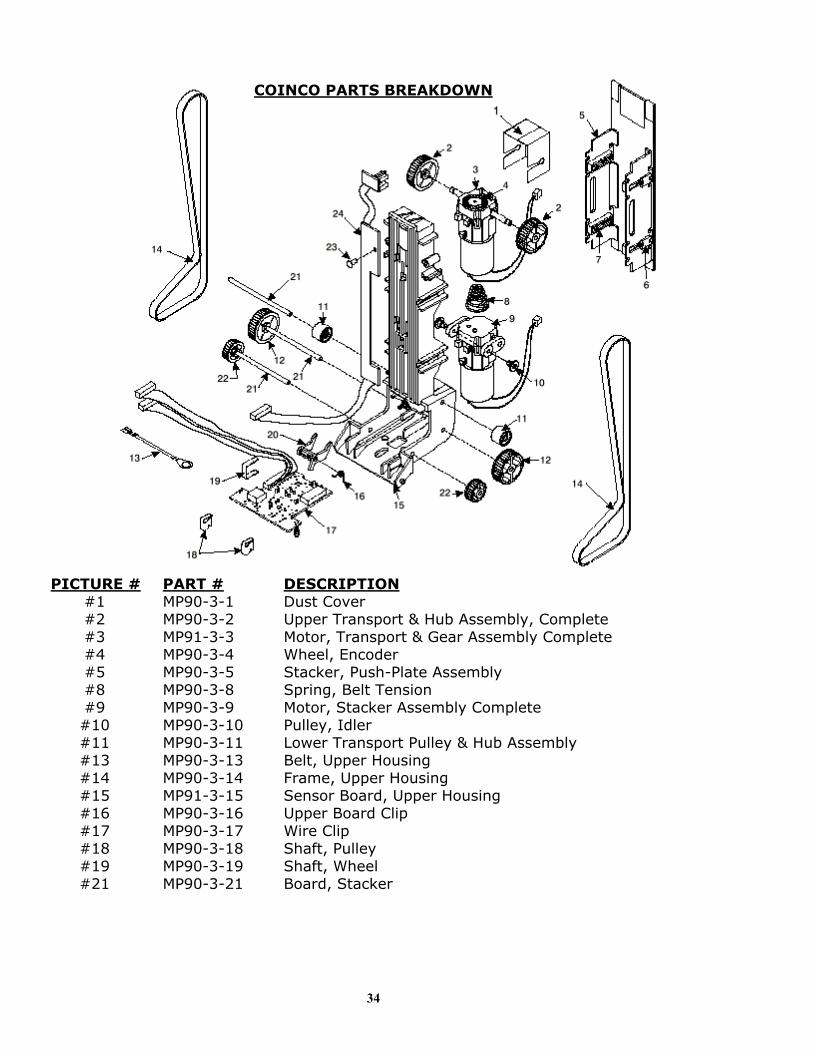
COINCO PARTS BREAKDOWN
PICTURE ##1#2#3#4#5#8#9#10#11#13#14#15#16#17#18#19#21
PART #MP90-3-1MP90-3-2MP91-3-3MP90-3-4MP90-3-5MP90-3-8MP90-3-9MP90-3-10MP90-3-11MP90-3-13MP90-3-14MP91-3-15MP90-3-16MP90-3-17MP90-3-18MP90-3-19MP90-3-21
DESCRIPTIONDust CoverUpper Transport & Hub Assembly, CompleteMotor, Transport & Gear Assembly CompleteWheel, EncoderStacker, Push-Plate AssemblySpring, Belt TensionMotor, Stacker Assembly CompletePulley, IdlerLower Transport Pulley & Hub AssemblyBelt, Upper HousingFrame, Upper HousingSensor Board, Upper HousingUpper Board ClipWire ClipShaft, PulleyShaft, WheelBoard, Stacker

35
MP90-4-IF
3
4
COINCO PARTS BREAKDOWN
PICTURE ##1#2#3#4#5
PART #MP90-4-1MP91-4-2MP90-4-3MP90-4-4MP90-4-IF
DESCRIPTIONLid, Logic board BoxBody, Logic board BoxMain Logic BoardSticker, Serial Number / WarrantyIntermediate Frame with Bearings

36
#8
MARS AE2600 SERIES 24VDC PARTS BREAKDOWN
PICTURE ##1#2#3#4#5#6#7#8#9
PART #AE93-1-1AE93-1-2AE93-1-3AE93-1-4AE93-1-5AC1045AE93-1-7AE93-1-8AE93-1-9
DESCRIPTIONStacker/Drive Assembly KitSensor Housing Assy, CompleteControl Board Cover, Plastic120VAC Logic BoardMain Chassis, Plastic500 StackerLED Housing Assy, CompleteBlack Front Bezzle, Plastic Metal Bezzle Support Plate (NOT SHOWN)
37
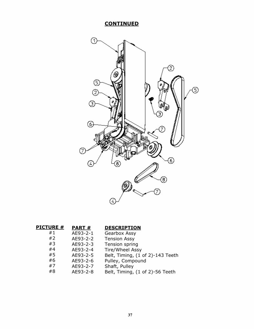
PICTURE ##1#2#3#4#5#6#7#8
PART #AE93-2-1AE93-2-2AE93-2-3AE93-2-4AE93-2-5AE93-2-6AE93-2-7AE93-2-8
CONTINUED
DESCRIPTIONGearbox AssyTension AssyTension springTire/Wheel AssyBelt, Timing, (1 of 2)-143 TeethPulley, CompoundShaft, PulleyBelt, Timing, (1 of 2)-56 Teeth
38
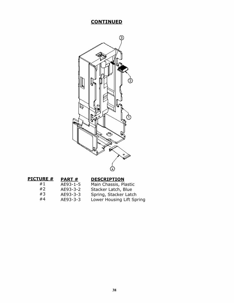
PICTURE ##1#2#3#4
PART #AE93-1-5AE93-3-2AE93-3-3AE93-3-3
CONTINUED
DESCRIPTIONMain Chassis, PlasticStacker Latch, BlueSpring, Stacker LatchLower Housing Lift Spring

39
Arizona3226 S. Fair LaneTempe, AZ 85282Phone: 602-431-0632Chris Mattingly
California11618 E. Washington Blvd.Suite # JWhittier, CA 90606Phone: 562-692-3059
FLORIDATampa6704 Benjamin RoadSuite 200Tampa, FL 33634Phone: 813-249-7338Bob Wilcox
Ft. LauderdaleAmerican Changer1400 NW 65th PlaceFt. Lauderdale, FL 33309888-741-9840RMA# Needed
Georgia4215 Wendall Dr SWSuite # EAtlanta, GA 30336Phone: 404-691-2777Chuck Crockett
Illinois862 Eagle Dr.Bensenville, IL 60106Phone: 630-860-2650Mike Durec
Louisiana524 Elmwood PkwySuite 190Harahan, LA 70123Phone: 504-734-0280Frank Case
Maryland6655 Amberton DriveBay “L”Baltimore, MD 21227Phone: 410-379-2680Bill LeJune
Massachusetts60 Prospect StreetWaltham, MA 02453Phone: 781-894-4525Kevin Cole
Missouri1236 Dielman Industrial CTSt Louis, MO 63132Phone: 314-725-0100Charlie Pavia
Ohio225 Corporate CourtSuite IFairfield, OH 45014Phone: 513-874-4460Joe Steddom
TEXASDallas3031 Quebec StreetSuite 115Dallas, TX 75247Phone: 214-638-3970
Houston2500 Central ParkwaySuite “K”Houston, TX 77092Phone: 713-683-6558Steve TenBarge
Washington1020 Industrial DriveBldg. 32Seattle, WA 98188Phone: 206-575-1999Carl Goodson

40
ALABAMABirmingham Vending Co.Mr. Gerald Spiegelman540 N. 2nd AvenueBirmingham, AL 35204Phone: 205-324-7526Fax: 205-322-6639Email: [email protected] Site: www.bhmvending.com
ARIZONAVendtronicsMr. Ken Van Leer4020 Grand Avenue, Suite #21Phoenix, AZ 85019-3173Phone: 602-973-3300Fax: 602-973-0033Email: [email protected]
CALIFORNIABetson WestMr. John McCann5660 Knott AvenueBuena Park, CA 90621Phone: 714-228-7500Fax: 714-228-7510Web Site: www.betson.com
Betson WestMr. Ben Fresenhazion213 E. Harris AvenueSan Francisco, CA 94080Phone: 650-952-4220Fax: 650-827-3420Web Site: www.betson.com
C.A. Robinson, Inc.Mr. James Tomei180 Utah AvenueS. San Francisco, CA 94080Phone: 650-871-4280Fax: 650-588-8538
G&K ServiceMr. Vince D’Agostino4364 Twain Avenue, Unit #4San Diego, CA 92120Phone: 619-281-9227Fax: 619-281-8706
Superior Sales & ServiceMr. Esko Wallace299 Old County Road, Suite 26San Carlos, CA 94070Phone: 800-995-8363 or 650-591-2193Fax: 650-591-1712Email: [email protected]
Trilogy Magnetics, IncMr. Ed Colmenares16250 Gundry AvenueParamount, CA 90723Phone: 562-663-1800Fax: 562-633-6408
COLORADOMountain Coin DistributorsMr. Jack Brown345 W. 62nd AvenueDenver, CO 80216Phone: 800-654-2646 or 303-427-2133Fax: 303-429-2104Email: [email protected]
FLORIDAV.E. South, L.C.Mr. Joe Gilbert4800 N.W. 15th AvenueFt. Lauderdale, FL 33309Phone: 888-837-6884 or 954-491-7300Fax: 954-491-7301Email: [email protected] Site: www.vesouth.com
Vendor's Repair Service, Inc.Mr. George Uilano6025 Cinderlane ParkwayOrlando, FL 32810Phone: 407-291-1712Fax: [email protected] Site: www.vendorsrepair.com
GEORGIANorth Atlantic Marketing*Mr. Kirk ChamblessNorcross Center2100 Norcross Parkway, Suite 130Norcross, GA 30071Phone: 800-442-2388 or 770-449-5001Fax: 770-729-1144
Southeastern VendingMr. Johnny Williams1886 Forge StreetTucker, GA 30084Phone: 800-825-8554 or 770-621-9055Fax: 770-621-9055Email: [email protected]
ILLINOISAmerican Vending Sales, Inc.Mr. Frank Manduno750 Morse AvenueElk Grove Village, IL 60007Phone: 847-439-9400Fax: 847-439-9405Email:[email protected] [email protected] Site:www.americanvending.com
INDIANAShaffer DistributingMr. Ron Dixon9461 E. Washington StreetIndianapolis, IN 46229Phone: 800-876-0789 or 317-899-2530Fax: 317-899-6080Email: [email protected] Site:www.schafferdistributing.com

41
LOUISIANASur Serv Corp.Mr. Julian Ortiz2920 Kingman StreetSuite 118Meltaire, LA 70006Phone: 504-887-1661Fax: 504-887-9081Email: [email protected]
MARYLANDBetsonMs. Angie Swann3431A Benson AvenueBaltimore, MD 21227Phone: 800-296-4100Fax: 410-646-2053Email: [email protected]
MASSACHUSETTSGekay Electronics Corp.Mr. Rob Collette16 Deer Park DriveE. Longmeadow, MA 01028Phone: 800-832-0028 or 413-525-2700Fax: 413-525-6886
MICHIGANWolverine American, Inc.Mr. John Paskeretti26400 CapitolRedford, MI 48239Phone: 313-937-4600Fax: 313-937-1802
Wolverine American, IncMr. John Paskeretti3400 Jefferson Avenue, SEGrand Rapids, MI 49548Phone: 616-452-2125Fax: 616-452-3319
MINNESOTAChanger Services, Inc.Mr. Mark Stolley7721 Pillsbury Avenue SouthRichfield, MN 55423Phone: 888-328-5067 or 612-798-3610Fax: 612-798-3614Email:[email protected]
Viking VendingMr. Guy Jones9549 Penn Avenue, SouthMinneapolis, MN 55431Phone: 800-879-0321Fax: 612-887-5656Email: [email protected] Site: www.liebermanmusic.com
MISSOURIGreater AmericaMr. Duane Zarger3230 Roanoke RoadKansas City, MO 64111Phone: 816-531-4300Fax: 816-531-4337
Midwest Associates, Inc.Mr. Glen Politte9334 Highway BBHillsboro, MO 63050Phone: 800-237-0521Fax: 636-789-5848Email: [email protected] Site: www.mwassoc.com
Shaffer Distributing CoMr. Chuck Ropke2111 January AvenueSt. Louis, MO 63110Phone: 314-645-3393Phone: 314-645-3689
MONTANAAction Gaming Technology*Mr. Harold HeyerP.M.B. 117425 N. 5th StreetMissoula, MT 59802Phone: 406-728-0034Fax: 406-549-0688Email: [email protected]
NEVADAMars Electronics International*2700 East Patrick Lane, Suite 1Las Vegas, NV 89120Phone: 702-597-4836Fax: 702-597-4837Email: [email protected]
NEW JERSEYBetson EnterprisesMr. Rob Zigmont303 Paterson Plank RoadCarlstadt, NJ 07072Phone: 800-524-2343 or 201-438-1300Fax: 201-438-4837Email: [email protected] Site: www.betson.com
Ellenby Technologies, Inc.*Mr. Bob Dobbins1460 Grandview Avenue, Unit 2MidAtlantic Corporate CenterWest Deptford, NJ 08066Phone: 856-848-2020Fax: 856-848-7080Email: [email protected]
NORTH CAROLINABrady Distributing Co., Inc.Mr. Roger Harrison2708 Yorkmont RoadCharlotte, NC 28208Phone: 704-357-6284Fax: 704-357-1243Email: [email protected] Site: www.bradydist.com
Southeastern VendingMr. John Hollar2748-B Interstate StreetCharlotte, NC 28208Phone: 800-825-8555 or 704-394-4911Fax: 704-394-3789Email: [email protected]
OHIOShaffer Distributing Co.1100 W. Third AvenueColumbus, OH 43212Phone: 800-282-0194 or 614-421-6800 Extension 114Fax: 614-294-2669Email:[email protected] Site:www.shafferdistributing.com
Vendors ExchangeMr. Brent Garson4020 Payne AvenueCleveland, OH 44103Phone: 800-321-2311 or 216-432-1800Fax: 216-432-2786Email: [email protected] Site: www.veii.com

42
OKLAHOMAAeco Sales & ServiceMs. Kacy Parker619 North BroadwayTecumseh, OK 74873Phone: 800-682-0358 or 405-598-2915Fax: 405-598-5506Email: [email protected]
OREGONMountain Coin Machine DistributorsMr. Michael Damtew6440 N.E. HalseyPortland, OR 97213Phone: 503-234-5491 or 800-233-5198Fax: 503-233-3816Email: [email protected] Site: www.mountaincoin.com
PENNSYLVANIAMEIMr. Al Serro1301 Wilson DriveWest Chester, PA 19380Phone: 610-430-2500Fax: 610-430-2694Email: [email protected] Site:www.meiglobal.com
SOUTH CAROLINADrew Distributing, Inc.*Mr. Gabe Mull9107 Ashville HighwayBoiling Springs, SC 29316Phone: 864-578-4444Fax: 864-599-6232*Limited Amusement ServiceCenter
TENNESSEEBrady Distributing Co., Inc.Mr. Brian Drost3306 Winbrook DriveMemphis, TN 38116Phone: 901-345-7811Fax: 901-398-0578Email:[email protected] Site: www.bradydist.com
TEXASAeco Sales & ServiceMr. Eddy Parker10290 Monroe Drive #206Dallas, TX 75229Phone: 214-352-4755Fax: 214-352-8154
Serv-A-Mech Electronics, IncMr. Jerry Camp5916 West 34th Street #BHouston, TX 77092Phone: 800-323-7214 or 713-681-6277Fax: 713-681-8570Email: [email protected]
UTAHWachtor ElectronicsMr. Larry Wachtor73 West Truman AvenueSalt Lake City, UT 84115Phone: 801-485-2289Fax: 801-485-8745
VIRGINIAEastern Commercial ServicesMr. Bob Vose813-A Professional Place, Suite 100Chesapeake, VA 23320Phone: 800-486-1020 or 757-436-1020Fax: 757-547-4772Email:[email protected] Site: www.easterncommercial.com
WASHINGTONWachtor ElectronicsMr. Larry Wachtor232 S.W. 43rd StreetRenton, WA 98055Phone: 425-251-0997Fax: 425-251-8532
WISCONSINPioneer Sales & ServiceMr. David DroppN55 W13875 Oak LaneMenomonee Falls, WI 53051Phone: 262-781-1420Fax: 262-781-4307Email: [email protected] Site:www.execpc.com1~pioneers
Viking Vending pf WisconsinMr. Brent McKennonN59 W16600 Greenway Circle Unit BMenomonee Falls, WI 53051Phone: 262-703-4168Fax: 262-703-4171Email: