Embed Size (px)
Citation preview

UNCLASSIFIED
AD NUMBER
LIMITATION CHANGESTO:
FROM:
AUTHORITY
THIS PAGE IS UNCLASSIFIED
AD893311
Approved for public release; distribution isunlimited.
Distribution authorized to U.S. Gov't. agenciesonly; Test and Evaluation; 17 APR 1972. Otherrequests shall be referred to Air Force FlightTest Center, Edwards AFB, CA.
ASD ltr 8 Feb 1974

. j
I
u ..
a.. 0 (..:)
L&.J --J -L.t...:
' ~
• FTC:.TR-9'1· 2
- ICO T
p
T c ICAL o . 71-
..IU
D c
AIR FORCI! FLIGHT T ST c•NTI!R I!DWA DS AIR FO Ca BAS , CALIPORMIA
._ ____ AIR FORCa YSTI! C,., MA D ----· UNITED STATIIS AIR PO C

I rcrrn
••
Qualified r quuters moy ohtoin copies of this report from the Defense Documentation Cent r, Com ron Station, Alexandria , Va . Deportment of D fense contract rs tt111st be eatoblithed for DOC services, or hove ''need to now " certified by cognixont military agency of th ir project or contract.
DOC release to OTS ia not outhorix d
When US Government draw in a, pecificotions, or other data are u .. d for any purpose other t on o definitely relot d government procurement operation, the government th r by incura no responsibility nor ony obligation whatsoever; ond the fact that ti-e government oy hove formuloted , furnished, or in onywoy supplied the said drowings , specifications, or ony oth r data is not to b regarded by implication Of otherwise , oa in any monner l'c nsing t e holder or any other pe rs on or corporation or conveying any rights or permission to mon' foctur , use or sell on paten ed invention at oy in any woy be related thereto .
Do not return !his copy, etain or destroy
0
1 o~n a.a I liST. U&IL * 1•
~

•fp*
4SH Wii>fa
DEPARTMENT OF THE AIR FORCE
HCADQUAWTER9 AERONAUTICAL SYSTEMS DIVISION (AFSC»
WRIGHT PATTERSON AIR FORCE BASE. OHIO 4S433
«Ftv TO . , ... ATTN or. ASD/SDQH 2-85 (Major Thompson/5/iM0/R&D 9-2/H-53)
suiJicT: ASP Addendum Report to FTC-TR-?!^
4«r*r',
f
TO: Recipients of FTC-Tft-71-26
This report is a part of and should remain attached to FTC-TR-71-26. Paragraph numbers below correspond to recommendations in fTC-TRF-71-2ö«
1 through 9. Concur with intent. ASD has initiated action to incor- porate the required information in the appropriate aircraft manuals. Those recommendations not already reflected in current manuals will appear in forthcoming supplements, changes, or revisions.
10, Concur with intent. The anticipated minimal exposure to icing conditions and the use of damage-avoidance procedures developed during these tests combine to reduce the possibility of significant increase3 in tail rotor replacement/repair coats. In the event service experie^e or future mission requirements indicate that rising costs merit consi'i- eration of alternate materials, the recommended engineering study should be undertaken. ASD plans no further action on this recommendation, pending future requirements, direction and funds. The recommendation should be considered for future helicopter procurements, if applicable,
11. Concur with intent, but not with recommended action. See comment in paragraph 10, above. In addition, clearance to operate in moderat: icing conditions does not require the use of special ice inhibiting materials. Therefore, unless future missions require flight in more severe icing conditions or other requirements dictate additional effort to reduce potential tail rotor blade maintenance, further investigations are not justified. The recommendation should be considered for future procurements, if applicable, especially for other helicopters less capable of tolerating ice.
12 and 13. Concur with intent. ASD has initiated action to incorporate the required information in the appropriate aircraft manuals. Those recommendations not already reflected in current manuals will appear in forthcoming supplements, changes, or revisions.
l/f. Concur with intent. Investigative and corrective actions which began with the receipt of UMRs will be completed according to normal procedures.
. ...i . 'rXiii,^■■■V^"i.'^■ "WW tÄ^-'-v-^j

r 15 through 17. Concur with intent. ASD has initiated action to incorporate the required information in the appropriate aircraft manuals. Those recommendations not already reflected in current manuals will appear in forthcoming supplements, changes, or revisions.
18. Concur, Since all aircraft have been delivered, the procurement of updating and modifications for H-53 helicopters has transitioned to AFLC System Support Managers. ASD recommends field corrective action by the TCTO process.
19. Concur. New windshields of improved design and different manu- facture are now undergoing service evaluation. Retrofit of delaminated windshields should be accomplishod on an attrition basis only.
20 through 26. Concur with intent. Since these recommcMdat.innn apply only to the test camera installation, no action is planned L'or the W-'/j aircraft or its systems. ASD will consider using the blade camera for future helicopter testing, as appropriate (to document rotor blade dynamics and/or icing phenomena). Incorporation of the recommended improvements to the blade camera should enhance its use during future tests.
27. Concur with intent, but not with recommended action. This recommendation should be considered for future tests involving the use of ice detector probes of this type. As explained in the test report introduction (under AIRCRAFT DESCRPTION, Ice Detector System), this instrumentation was peculiar to the test helicopter. The recommendation does not apply to the standard configuration H-53 which does not use an ice detector probe.
GENERAL COMMENT: Procurement of the (ISAF HH/CH-53B/C was directed "off- the-shelf" with minimum modifications to the existing USMC CH-53A con- figuration. Directed lead times did not allow normal development pro- cedures to be followed. For example, cockpit mockup inspection was precluded by the expedited procurement process. Initially no Category II tests were authorized. Deployment to combat prior to adequate testing allowed the operator to accumulate extensive experience in operating the system. Based on this experience, user requirements must be care- fully considered in evaluating recommendations from testing. In some cases the costs associated with some desirable changes may not be commensurate with the system benefit or with the priority of user requirements. Numerous recommendations contained in this report should be considered in future procurements, if appropriate.
FOR THE COMMANDER
WILLIAM IX EASTMAN, JR., LT COL, USAF Chief, Helicopter Programs Division directorate of Combat Systems Deputy f«>r Systems
■ w»w *i ■*-

-9—
FTC-TR-71-ae
CATEGORY II ICING TEST OF THE HH-83C HELICOPTER
DONALD J.DOWOEN Icing Pnjiet Englnur
GREGORY A.M. ETZEL Mijir, USAF
Systmi Prallet Entimir
CLARK E.LOVRIEN, JR. Major, USAF
Pnjiet Offictr and Prajict Pilot
for *'ni
W
/
^^^WW^WV^
J -X- -'■" 7
i^ >» i i» wmm
- ■ ' •■-• ' - iii

,til'äitilliliU!«"r''"'J'"''""" 1 FOREWORD
This report presents the results of the icing test phase of the Category II All-Weather Test Program of an HH-53C helicopter, USAF S/N 68-10354. The artificial icing tests we/e conducted at Eielson AFB, Alaska, during the period 19 March be«^31 March 19 71. The natural icing tests were conducted at Elmendorf AFB, Alaska, during the period 3 April to 10 April 1971. Data results from the reductici of photo and magnetic tape recordings will be published separately at a later date in appendix VIII, reference 1, of this report. The program originated with the assign- ment to the Air Force Flight Test Center (AFFTC) of the Category II All- Weather Test mission as outlined in an Air Force Systems Command (AFSC) Program Action Directive, dated 16 March 19 70. This program action di- rective tasked the AFFTC to complete the Category II All-Weather testing of the HII-53C beginning witn the termination of the Climatic Laboratory testing then being conducted at Eglin AFB, Florida, by the Aeronautical Systems Division (ASD). The icing tests were conducted under the author- ity of AFFTC Project Directive No. 71-24 with AFFTC priority 31 and Job Order Number 482AEO.
The cooperation and the support of the personnel of the 5010th Combat Support Group, Eielson AFB, Alaska, of the US Army Arctic Test Center at Fort C7reely, Alaska, 11th Weather Squadron, and the 5040th Helicopter Squadron at Elmendorf AFB, Alaska, were greatly appreciated.
Foreign announcement and dissemination by the Defense Documentation Center are not authorized because of technology restrictions of the U.S. Export Control Acts as implemented by AFR 400-10.
Oronvti hv
^^^vCx^w_ DONALD J. OOWUf N Icing Project Engineer
GREGORY A.M. ETZEL Major, USAF Systems Engineer
Reviewed and approved by: 10 May 1971
/ 'J O ■ - / THOMAS/CECIL Colonel, USAF Commander, 6510th Test Wing
ROBERT M.WHITt Brigadier General, USAF Commander
CLARK E. L0VRIEN, JR. Major, USAF Project Officer and Project Pilot
SIDNEY E. GURLEY Major, USAF Pilot

•ipw
ABSTRACT Artificial icing tests were conducted during 19 through 31 March
19 71 at Eielson AFB, Alaska. Natural icing flights were conducted during 3 through 10 April 1971 in the vicinity of Elmendorf AFB, Alaska. The helicopter and its anti-ice systems operated satisfactorily under all artificial and natural icing environments encountered. Rotor blade ice shedding was random and caused damage to rotor blades in the form of dents and punctures. Tail rotor blade dents occurred throughout all ic- ing encounters (light and moderate conditions) when ice shedding took place. Tail blade punctures were noted during two flights in artificial icing conditions and once in natural icing, when the outside air tempera- tures (OAT) were approximately -15 and -18 degrees C. Colder temperatures (-18 degrees C) caused the ice to form farther out toward the main rotor blade tips, which resulted in a larger angle of incidence between shedding tip ice and the tail rotor blade plane of rotation. This increased the potential for puncture damage to the tail rotor blade pockets. Main rotor blade damage in the form of dents from ice strikes occurred occasionally during the icing program at the colder OAT's (below -15 degrees C) . Rotor blade damage encountered was not judged to be a safety-of-flight hazard. The Engine Air Particle Separator (EARS) system functioned satisfactorily with inlet doors closed in light and moderate icing conditions with no engine performance degradation noted. The EAPS was tested at airspeeds up to 160 KIAS, doors closed, with no structural or engine performance degradation noted. Airframe ice was of no consequence to the operation of the flight controls and the overall operation of the helicopter. The HH-53C should be cleared for flight in light and moderate icing and freez- ing rain conditions with or without EAPS installed, but such flights should be restricted to mission essential operation only, based on the probability of the occurrence of rotor blade pocket damage caused by ice strikes from shedding ice.
Ill
w* mm*mmm

1^-
TABLE OF CONTENTS
LIST OF ILLUSTRATIONS. LIST OF ABBREVIATIONS INTRODUCTION
General Program Objectives. Test History Aircraft Description.
Ice Detector System. Machmeter Heater Duct Modification, Heating System Auxiliary Power Plant.
TEST AND EVALUATION Icing Analysis
General
\
Test Procedures. Test Results
Operational Analysis General Test Results. Natural Icing Tests. Operational Summary,
Systems Evaluation General Test Objectives.. Test Procedure — Test Results
CONCLUSIONS AND RECOMMENDATIONS. General Icing Evaluation Operational Analysis. Systems Evaluation..
APPENDIX I - TEST SUMMARY (SYSTEMS) APPENDIX II - HH-53C ARTIFICIAL AND NATURAL ICING CONDITIONS. APPENDIX III - ICING DEFINITIONS APPENDIX IV - ROTOR BLADE ICE SHEDDING (ARTIFICIAL ICING) APPENDIX V - ROUTINE UNSATISFACTORY MATERIEL REPORT SUMMARY APPENDIX VI - HH-53C EAPS STATIC DIFFERENTIAL PRESSURE CALIBRATION. APPENDIX VII - ICE DETECTOR RELIABILITY REFERENCES
Page
_v _vi II _l _1 _2 _2 _3 _5 _5 _5 .5 .6 .6 .6 .6 .8 .20 .20 .20 28 29 30 30 31 31 31 39 39 39 40 43 45 46 49 50 51 52 53 54
iy
"■ - •■ ■ M .'-■■ A*. -■—■-- 3 a I"."1'!. »»"**».*•*?<■;'•*

LIST OF ILLUSTRATIONS
Figure No.
1
2
3
4
5
6
7
8
9
10
11
12
13
14
15
16
17
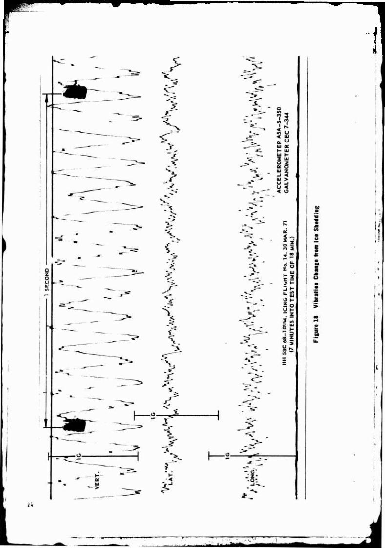
18
19
20
21
22
23
24
Title
Rotor Blade Camera
Page No.
Overhead Cockpit Control Panel
C-130 Icing the HH-53 Helicopter
Typical Ice Accumulation on HH-53_
Iced-Over Heater Inlet Duct Screen.
Typical Ice Accumulation in Natural Icing.
Ice Fingers on EAPS Mini Screens
Solid Sheet of Ice on EAPS Lips and Doors.
Ice Fingers on EAPS
Natural Ice on F.AP8 Aft Rupnort Rlnqfl.
Advancing Rotor Blade in Icing Cloud _
Artificial Blade Ice Compared to Natural Ice on Blade
Artificial Blade Ice Compared to Natural Ice on Blade
Ice on Top and Bottom of Blade Spar
Damage to Tail Rotor Blades
Rotor Blade Ice - Artificial vs. Natural.
Vibration Change from Ice Shedding.
Vibration Change from Ice Shedding.
Glime Ice on Refueling Probe
Ice on Flight Servos and Anti-Flapping Restrainers
Ice Slab from EAPS Door (Flight 13)
Windshield Delaminations
Windshield Delaminations
Heater Inlet Screen with Ice Detector Probe Inside
. 7
. 8
. 9
.10
.11
.12
.13
.14
.16
.17
.17
.18
.19
.21
.22
.24
.27
.27
.33
.35
.35
.38
**" " TT

,1 tun- .,J—.»^■J»af.v»«!««<.^i»'rifiMi|,Mli»iii,l
LIST OF ABBREVIATIONS AND SYMBOLS
Item
A DP
AFCS
AGE
APP
APRS
ASD
ATC
EAPS
FOD
FPS
IFR
KTAS
LWC
MRB
Ng
Nr OAT
Pa
RUMR
TCTO
T5
UMR
WUC
Definition
Aerodynamic Discontinuity Principle
Automatic Flight Control System
Aerospace Ground Equipment
Auxiliary Power Plant
Aerospace Rescue and Recovery Service
Aeronautical System Division
Air Traffic Control
Engine Air Particle Separator
Foreign Object Damage
Frames Per Second
Instrument Flight Rules
knots indicated airspeed
liquid water content
main rotor blade
gas generator speed
rotor speed
Outside Air Temperature
Pressure Altitude
Routine Unsatisfactory Material Report
Time Compliance Technical Order
Turbine Inlet Temperature
Unsatisfactory Material Report
Work Unit Code
Units
knots
grams/meter~
percent
percent
degrees C
feet
degrees C
'- - :-■ [^a^SSM

INTRODUCTION GENERAL
The test helicopter, S/N 68-10354, was a rescue version of the H-53 and was similar to the CH-53C. The primary mission was search, location and recovery of combat crew members in all environments. The secondary mission was delivery of supplies to forward combat areas. The aircraft systems were instrumented to record environmental effects. ThQ flight summary with the applicable parameters is presented in appen- dix1 I.
' The icing Lest was the fourth in a series of environmental tests conducted on the HH-53C. The Adverse Weather test (reference 2), the Climatic Laboratory test (reference 3) , and the Arctic test (reference 4) were accomplished previous!/. A U.S. Navy evaluation on the CH-53A under icing conditions was completed in 1966 (reference 5). Other HH-53C Category II test results will be presented in future AFFTC technical re- ports as tests are completed. A future test that is presently scheduled foe the HH-5 3C is the desert environmental test. T tOIR PROVRAM OBJECTIVES
The purpose of the icing test was to determine the operational suita- bility of the HH-53C systems and components in artificial and natural icing conditions up to and including moderate icing. Moderate icing is defined as the accumulation of one-half inch of ice on a small probe per 20 nr.les. ^Specific test objectives were:
To'eValuate main rotor blade and tail rotor blade ice accretion/ jShedctLng characteristics in moderate artificial and natural icing conditions.
2. To evaluate any aircraft damage which might be caused by ice shed from the rotor blades.
3. To determine airframe and rotor blade ice accumulation/shedding characteristics in freezing rain conditions.
4. To evaluate the EAPS under icing and freezing rain conditions.
5. To evaluate rotor blade ice accretion characteristics in moderate icing conditions with rotor blade aerodynamic discontinuity prin- ciple (ADP) (anti-ice) tape installed (reference 6).
6. To determine icing operating procedures to be included in the Flight Manual (T.O. 1H-53(H)B-1) (reference 7).
7. To compile environmental data for future fixes, modifications, and design purposes.
8. To evaluate the performance of a motion picture camera installed on a main rotor blade sleeve and spindle housing.
1
EBE jr«!»

IliwaBiiiiJWfctiWth^r.K«.^ a*
TEST HISTORY
'rhn new test vehicle, HH-53C, S/N 68-1Ü354, and test instrumentation were originally accepted by the Air Force at the Sikorsky Aircraft plant at Stratford, Connecticut, on 4 December 1969. Subsequently, adverse weather tests and Climatic Laboratory tests were conducted by the Aero- nautical Systems Division (ASD), After the Climatic Laboratory test, the responsibility for conducting Category II tests for the HH-53C was transferred to AFFTC at Edwards AFB, California. The HH-53C was then flown to Eielson AFB, Alaska, where Arctic tests were completed during the period 6 January to 26 February 1971. Following the Arctic tests, the aircraft remained at Eielson AFB for the purpose of conducting the artificial phase of the icing program. The artificial icing tests were conducted from ]9 through 31 March 1971. The aircraft departed for Elmendorf AFB, Alaska, on 3 April 1971 to seek natural icing conditions. The natural icing phase was completed on 10 April but systems evaluation continued until 1"^ April at which time the helicopter returned to Edwards AFB, California.
AIRCRAFT DESCRIPTION
The HH-5 3C helicopter was manufactured by Sikorsky Aircraft Division of United Aircraft Corporation, Stratford, Connecticut. Power was pro- vided by two T64-GE-7 engines which could be protected from foreign object damage (POD) by installation of engine air particle separators (EAPS). All-weather capability was provided by an automatic flight con- trol system (AFCS), engine and windshield anti-icing systems, and instru- ment landing and navigation systems. The helicopter was equipped with a hydraulic rescue hoist, strategically placed armor plating, armament consisting of three pintle-mounted 7.62ram miniguns, external auxiliary fuel tanks, and an aerial refueling system. The cargo compartment was equipped with two cargo winches, roller conveyors in the cargo compart- ment floor, cargo and litter tiedown facilities, and troop seat provisions An auxiliary power plant (AFP) provided a seif-starting capability, power for cargo loading and unloading, and aircraft systemn checkout while on the ground. The tricycle landing gear was retractable and a retractable tail skid provided tail rotor protection on landing.
The H!!-53C helicopter used during the Arctic tests was in standard configuration except as noted in this section. The helicopter was in- strumented with a low-speed digital airborne tape recording system. Each tost parameter ^as sampled three times per minute. A photopanel was also installed x.o monitor selected system parameters. A motion pic- tiro camera was installed at the pitch horn attachment point on a main rotor blade sleeve and spindle housing with a counter weight on its cor- responding opposite blade (figure 1). This camera was operated during the icing test to photograph the buildup and shedding of ice from a main rotor blade. The outputs from three cockpit mounted accelerometers were recorded by an oscillograph. EAPS internal static pressure was compared t.n aircraft static pressure from the pitot static system, and this informa- tion was presented in the photopanel. The following paragraphs described systems modified or added to this test helicopter.
■■ ■ ■' Tg

Ice Detecter System
Th est h li op e pro i ed visu 1 indi detector c on ~ol cuits. Th e · e consiste d o swi marked ICE DET ( i the sys e f nc i0n TE T pos i t ion, t he s e n s in elemen , o vibra ing t · e whose n a c um 1 ted . then he lay closed a nd t he i for a period of iv
F i(trt 1 Rlftf Ill. I C• erl
to shed the s ma ll mount o ic The ligh t on the ice d e ec or An ice dete ctor w r i ng l ight system received owe r r o m the c ircui t b r e ak ers ma r ked I CE D T panel .
r i irr o l panel , and a ligh
as i e 1 e , a r eact i v t ed

Figure 2 Overhead Cockpit Control Panel
— *" - ■ • •'■ ■ i" ^-~-~z^~**-**

Maclllltttr
Prior to Arctic testing, the copilot's airspeed indicator was replaced with an advancing blade tip machmeter. The indicator was designed to continuously indicate the Mach number at the t ip of the advancing rotor blade. It received signals conti nuously from the pitot-static system with adjustments for variations in rotor speed made manually t o the dial face by the copilot . FTC-TR-71-11 (refere nce 8) pr s nts the r e sults of tne machmeter tests.
Heater D1ct MHiftcatltl
by mountin an bulkhead . Th
\vas requir could be the he t ion d
MeatiiC Systltll
The
e in i
Auxili•y Pewtr Pl11t
in was no substitu This was l.
Ex ep o r t he o llowin , t he APP wa th Fli h an u 1 (r e r nee 7) .
tion .
w s made av ilable t of the pilot ' s
1 d iam ter (5 -3/ 4 ) , wh ich bled hot
ed th t hea whe r e it , the flex i ble hose
ad t r r e urning a pro o ype install -
in th e o m icall~'
c bin or COCK PIT
ion
at the r e h ater
a m a s descr ibed in the
An addi ion 1 ac umula or with a 150-cubi c in h c acity w s in-st l le d nex to the existinq 250-cubic inch a ccumul tor . The a dditional
ccumul t o r p r o v i ed an incre se s rt c p ili y f or tern er tures down o - 6 5 degrees F (-54 de grees C) . Am nu lly o er ted v lve loca ted
between t he two accumul tors was o ened when t he addition 1 ene r gy from the second a ccumulator was n eded for starting .
APP Bootstrap Modification .
The hand pump used to charge the APP accumulators cavitated duri ng cold weather o perations . This was evidenced by either pump handle springback or complete lack of res istence during a pump pressure stroke. To p r even t this, t he utility hydraulic reservoi r was statically pressurized by using a 3-cubic inch accumulator, which in turn created a positive 30 - psi head pressure at t he inlet s ide of the APP handpump.
I

APP Start Valve Modification.
AFP start problems occurred at cold temperatures in the climatic laboratory due to restricted flow through the APP start valve. A modified valve (P/N OMP 2830-11), incorporating a change in the control orifice size, was instal d at Eielson AFB on 11 January 1971.
APP Heavy Duty Clutch.
The APP clutch shaft sheared during the arctic tests. It was re- placed by a heavy duty clutch used on the Marine versions of the H-5 3, The modification incorporated the larger diameter clutch, shorter APP-to- clutch drive shaft, slightly modified lubrication lines, and a different oil dam on the accessory gearbox at the clutch pad.
TEST AND EVALUATION
ICING ANALYSIS
General
Artificial icing and freezing rain tests were conducted on the HI1- 53C to determine the capabilities of the overall aircraft in an icing/ freezing rain environment. Natural icing tests wore conducted to verify and substantiate artificial icing results. The artificial icing tests were conducted with the HH-53C in four specific configurations:
1. E/PS not installed.
2. EAnS installed on No. 2 engine, doors opened.
3. EAPS installed on No. 2 engine, doors closed.
4. Aerodynamic Discontinuity Principle (ADP) anti-icing tape installed on main and tail rotor blades, EAPS installed on No. 2 engine, doors closed.
Test Procedures
Artificial Icing.
The artificial icing tests were flown at specified distances behind a C-130 equipped with a water spray nozzle (figure 3). The time in the icing cloud was then varied to obtain a desired total accumulation of ice. A test observer in the C-130 spray tanker used a hand-held range finder and the UHF radio to assist the helicopter pilot in maintaining the desired distance behind the tanker. Because of the relatively small diameter of the icing cloud in relation to the large rotor diameter of the HH-5 3C (72 feet 3 inches) , an attempt was made to center the right engine in the middle of the icing cloud. This allowed maximum buildup on the center and right side of the fuselage and immersed the advancing blc.do in the icing cloud.
^ r- r.—: - -"--vw >■ .r^- ' •• i

^'^ ... . ■ :.-y,;
»■.
WmmmBva
Figure 3 C-130 Icing the HH-S3 Helicopter
Different rates of buildup and types of ice were obtained by varyi:. ; the distance, water content and temperature. Ice thickness measurement.' were made immediately after landing during postflight inspections.
Artifici-il Freezing Rain.
This test was conducted under the same test procedures as in the icing test, using the icing water spray nozzle. The test helicopter was positioned closer to the spray nozzle than in the icing program, providin.j a simulated rain condition. Due to the small cross section diameter of the spray cloud at 300 feet behind the spray tanker, only the EAPS and its immediate area wore heavily immersed, although the entire helicopter was exposed intermittently to the freezing rain.
liatural Icing.
Weather briefings were received in the morning and afternoon to determine the most probable area of moderate icing. The flight areab were limited because of the mandatory requirement to be under radar coi trol at all times. When airborne, pilot inflight reports were monitor-. : for actual reports of icing and if the occasion presented itself, the helicopter was vectored by ATC to the area of the reported icing. When icing conditions were encountered the following parameters were recorded. The duration of the icing encounter, the thickness of the buildup, the indicated airspeed, and the outside air temperature (OAT) . From this data the determination of the type, as well as the intensity, of the icing was made.
^^^M

Test Results
Airframe.
Artificial Icing
Icing flights are summarized in appendix II. The terminology used in describing icing phenomena listed in appendix III wore extracted from reference 9.
Ice accumulated on the vertical pylon, hori/.ont.al tail, rotor hub, flight controls, refueling boom, external sponsons, tanks and aircraft nose (figure 4). The rescue hoist accrued heavy Lee throughout most of the test conditions. Maximum ice thickness of 1-1/4 to 1-1/2 inches was accrued on the previously mentioned airfrnmo areas from artificial icing conditions of icing flights 9, 14 and 15. No structural damage was in- flicted on the HH-53C airframo during all icing tests. Ice accumulation did not hinder flight control operation.
»
!
Figure 4 Typical Ice Accumulation on HH-53
■ * • * '-> r ii' w'ktm mmm
i i
i

The refuelinq probe was operated during icing flights 5, 9 and 14 with no mechanical problems evident.
The cabin heater i nlet screen had an estimated 75 to 90 percent i r f low blockag~ on icing flights 8 and 9 respective ly, due to glime
ice o rma ion on the screen (figure 5). Subsequent tests conducted at cold e r out side air temperatures (OAT) had minor (10 percent) b lock ge of t he hea ~r screen are a (icing flights 14 and 15). The cabin h eate r was inopera tive throughout part of th . artificial icing tests ; however, it was be l ieve d that this condltion d id not s · ni ic ntly change the
tt rn o the ice buildup on the he t e r s cr en (appendix I I ) . The he r i nl scr e n could be totally blocked of by ice forma ions should li ht or mode r t icing conditions at OAT's from 0 de grees C thro ugh -13 d gre s b encountered for extended peLiods of t i m . The h ate r was ino era ive during most of th flights when signific nt ice a cc r e tions
he • e le r i nle t occurred . Possible h ter syst m d amag or er r at ic r tion du t o r educ d a i rflow mi h result from heater o pe r tion after he e r 1nlet duct was ic d over. If r due d a i rflow from t he heate r
1 t l ized while flyin in icing conditions t he he te r t o preclud~ possibl h e ate r d mage . A NOTF. t o
b e included i n s c ion IX of the Flight Man 1 . (R 1) 1
FICirt I lcd·Ottr Hllttr llltt DICt Scr.n
I Numb rs ind icated o• (R 1 ), etc., reptesent th~ conesponcling recommendation numbers as tabulated in 1h Conclusions and Recommpdations section of this repcart.
I

Artificial Freezing Rain
o ice buildups affecting f l i ght controls occurred during t h e arti ficia l ree zi ng rain t est , ( ble I, appendix II , icing flight 13 ) . i-:aximum a i rframe ice was 1-1/4 i nch on the rotor hub and heat r inle t s cre ens . Th q heate r inle t scr en was 90 percent blocked due t o ice formatio s . No s truc ura l damage was note d during th post f li gh t inspecti on .
Natur 1 Icing
Ice acc umul ted in varying thi knesses (1 / 16 to 9/ 16 inch) on a irfr me componen s . The a ir r me com onen·t s which r ecei v d the most ic becaus of t heir coll ction e icie~py were th windsh ield wi ers , th fo rward HF ant nna mast , resc ue hois t a nd suppor memb r s (fi ure 6) . Th ese components we r e visible f rom i ns i de t he ai rcraf . Be e use t he sur face tern e r ture aver ged a ove f ezing (36 d r ees F) during the t ests it was imoossib le t o ev lua e ic buil u on such areas s t he tail boom , roto r he ad and f l igh c o ntrol s rvos , c bin he ter i nlet duct screen , and rotor b lades be fore the ic m l ed or was s hed . At no t i me durin he fl i hts id airfr a p r oblem or h z rd .
F icure 5 TnJiCII tee Acc111111t1H i1 11t1r11 lci•c
lD

Engine Air Particle Separator (EAPS).
Artificial Icing
A trace of ice buildup was noticed inside the EAPS ducting after icing flight 11 (EAPS doors opened) . A maximum of 1/4 inch glime ice collected on the EAPS inlet lips and door edges. Ice fingers built up and out from the EAPS mir. screens on the forward one-third of the EAPS (figure 7).
Figure T Ice Fingers on EAPS Mini Screens
Icing flights 12 through 15 were conducted with EAPS doors closed. Ice accumulated 15/16 inch and 1-1/2 inch thick on the EAPS inlet lips during icing flights 12 and 14 respectively (appendix II). A solid sin of ice formed over the doors and lips during icing flights 12 and 14
11
.^^«MMrtH^taiii

f1 _ur 8). The approximate maximum thickness of ice on the doors was 4 inch on icing flight 14. No ice was noticeable inside the EAPS dur
the artificial icing tests with the doors closed. Ice fingers formed n the leading edges of the mini screens on the bottom and the vertical
i board EAPS panel (figure 9). Maximum EAPS mini screen ice blockage ~ as es timated at five percent on icing flight 14, appendix II.
FiCirt I Sell~ Sllttt If Ice 11 EAPS Li'l -~ D11rs
Artificia l Freezing Rain
A p roximately 20 of t he 759 EAPS min i screens were blocked with l/8 !.': ic on icing flight 13 (appendix II) . The inboard EAPS panel was
r ce nt blocked off wi th ice. Ice fingers were l-15/32 inch long on d i n edge of the mi ni scre ens and on parts of the scre ens on the l/3 of the EAPS . Ice was 5/16 inch thick inside of the closed
!.'f<, h orw rd lowe r surface , due to \o ate r runback.
2

Figure 9 Ice Fingers on EAPS
Natural Icing
The EAPS performed satisfactorily under all natural icing and snow conditions encountered. The EAPS doors were usually left in the open position during cruise until the first indications of icing were observed, At that time, the doors were closed and left closed until the inlet lips and doors v/ere visually checked to be ice free. The maximum amount of natural Ice was collected on the EAPS on icing flight 21. About 30 per- cont of the leading edges of the mini screens on the inboard (vertical) KAF'.S panel wore observed to have rime ice formations.
13

l
ng i nes and Engine Air Anti-Icing Systems.
Ar t ificial Icing/Fre ezing Rain/Natural Icing
The engi ne s functioned sati sfactorily under all test conditions. The e ine a i r i nlet and air anti-icing systems functioned satisfactorily under all ici ng conditions encountered. Without EAPS installed, ice col lec ed a round the oute r periphery of the engine inlets on the EAPS a f s upport rings (figure 10). None of this ice was observed to shed or e n e r the engine inlets. No engine damage was experience d during all i cing test con itions . Engine operation with EAPS installed and doors c losed i n i ci ng conditi ons up to moderate was unaffected by ice buildup o n the EAPS . The EAPS, when operat~ ' with doors closed, precluded the possibility of engine FOD from ice ingestion.
INSTIUMIMTAnON TAPE
Ficure 11 lltlrlllce •• EAPS Aft S.Ntrt 111111

The EAPS should be cleared for flight in icing conditions up to moderate with the doors closed. If icing conditions are encountered inflight with EAPS installed, the EAPS doors should be closed immediately to prevent the possibility of engine FCU from ice shed from the rotor system or off the EAPS inlet lip or doors. Once closed, the EAPS doors should not be opened again until the EAPS doors are visually checked clear of all ice in flight, or the helicopter is on the ground with the engines stopped. (R 2, R 3, R 4)
Rotor Blades.
Artificial Icing
Both the ice accretion characteristics and the types of ice accumu- lated on the main and tail rotor blades varied in thickness and type dur- ing the artificial icing phase. The types of ice encountered were rime, glime, and clear (appendix III). Generally rime ice formed at OAT below -14 degrees C, glime ice formed between -7 through -14 degrees C, and clear ice formed between 0 and -7 degrees C. The spanwist blade ice accretion characteristics were directly related to OAT. Teuperatures between 0 and -12 degrees C caused ice to adhere tenaciously on 75 per- cent of the blade span and temperatures below -12 degrees C generally caused ice to adhere tenaciously on 100 percent of the blade span. The artificial icing cloud was not large enough in diameter to encompass the entire rotor plane (both the advancing and retreating blades), but the cloud was large enough to provide an icing condition for the entire ad- vancing blade (figure 11). Ice that formed on the blades was judged to be representative of typical ice formations found in natural icing con- ditions. Glime ice buildup on icing flight 9 ran underneath the spar, back to the pockets, and rime ice on icing flight 14 formed a 1-1/2 inch wide opaque band along the spar leading edge. Both conditions were repre- sentative of ice found in natural conditions (figures 12 and 13). The thickness of ice that accrued on the rotor blades throughout the artificial icing tests ranged from 1/16 inch (icing flight 1) to 1-1/8 inch (icing flight 15). All main rotor blade ice thicknesses presented were measured at the fourth pocket out from the rotor hub on the blade leading edge.
Aerodynamic Discontinuity Principle (ADP) tape (reference 6) was installed on the main and tail rotor blades after icing flight 14 to determine if the tape would discourage ice accumulation on the blade leading edge and induce earlier ice shedding due to reduced adhesion. The 12 mil thick ADP tape was designed for the H-3 helicopter blade, not the H-5 3 blade. Prior to the tape installation, all rotor blade spars were cleaned with isopropyl alcohol and then thoroughly wiped dry. Evaluation of the ADP tape was conducted on icing flight 15 which had the same test conditions as the previous icing flight. The ice accretion characteristics of the blade were changed. Ice formed farther back on the spars' upper and lower surfaces than experienced previously on icing flight 14 (figure 14). Also, the thickest and most defined accumulation of ice to date was noted (1-1/8 inch) on the main rotor blades. Possibly, the ice accrued further back on the top and bottom of the blade due to the spar being cleaner, i.e., oil free, from the alcohol cleaning. The ADP tape and cleaner blade leading edges apparently increased the water catch efficiency (ice accimulation rate) and the adhesion of the ice on the leading edges, when compared to the same test conditions encountered on the previous flight. Ice formed on the entire blade span, duo to the cold temperature at the test point.
IS
'-' - ii

•-.''if 7*)yl
•i-if ,€.;?/?:•
/ ....
«SUju.. *" lÜftw. l.'u|fcl
Figun 11 Advancing Rotor Blado ii Icing Cloud
" i rniTW -•-•" - ' ■ — A

ÜP
RIME ICE
ARTIFICIAL ICING
ICING FLIGHT 14
RIKE ICE
NATURAL ICING
ICING FLIGHT 20
Figure 12 Artificial Blade Ice Compared to Natural Ice on Blade
GLIME ICE
NATURAL ICING
ICING FLIGHT 21
GLIME ICE
Figure 13 Artificial Blade Ice Compared to Natural Ice on Blade
n
i i, l<tjMa^MiMM,Ma,M^l

m&v"'
i,
!/'
ROTOk IUOE
ICWG PLIGHT 14
(CLEAN LEADWC EDGE)
Flgun 14 lei in Tip ani Bittim if Bladi Spar
Typical blade ice shedding occurred first from the tail rotor blades and then from the main rotor blades. Shedding usually occurred from the midspan and tip areas, and was generally asymmetric. Main rotor blade ice shedding was random throughout the circumference of rotation, but the ice thickness at which shedding occurred could be predicted, based on the measurement of ice remaining on the rotor blades at the termination of the flight and an assumed approximate average rate of ice accumulation, (appendix IV). Ice from the main and tail rotor blades typically shed when the accumulated ice thicknesses reached approximately 1/2 and 1/4 inch, respectively. Tail rotor ice shedding did not cause any airframe damage or aircraft control degradation. Main rotor blade shedding was significant and caused main and tail rotor blade damage and airframe vibrations. Ice shedding that occurred on icing flights 5 and 15 resulted in minor dents and holes on the tail rotor blade pocket skin. After icing flight 5 one tail rotor blade had two holes, 3-3/4 by 2 inch and 2 by 1 inch, and after icing flight 15 two tail rotor blades had a total of three holes of 7/8 by 1-1/4, 1/2 by 1/4, 2-1/2 by 1-1/4 inch (figure 15). The damage did not degrade the structural integrity of the blades and did
18
, , 'A -
MM. mmM *^M m A

1 SKIN HOLES
SKIN HOLES
KING FLIGHT IS
Figure IS Damage te Tail Rotor Blades
not present any immediate safety of flight hazards. Generally tail rotor blade damage occurred at colder OAT's, when ice accumulated on 100 percent of the main rotor blade span. Colder temperatures (-18 degrees C) caused the ice to form farther out toward the main rotor blade tips, which resulted in a larger angle of incidence between shedding tip ice and the tail rotor blade plane of rotation. Damage, in the form of dents, was inflicted on the tail rotor blades consistently throughout the icing tests, however, the only danage requiring tail rotor blade replacement occurred during icing flights 5 and 15. Main rotor blade damage occurred occasionally in the form of small dents in the pockets due to ice strikes.
Main rotor blade ice shedding was random (occurring at anytime in flight) and tail or main rotor blade damage could occur at any time dur- ing flight in icing conditions (light and moderate icing). Shedding patterns on icing flight 15 were significantly different than previous flights (ADP tape installed). The ice that formed on the entire leading edge shed later than on previous icing flights. When the ice finally shed it had built up sufficient mass to cause tail rotor blade pocket damage (holes). The ADP tape as evaluated was unsatisfactory for H-53 helicopters.
Freezing Rain
Icing flight 13 was a simulated freezing rain condition. The rotor blades accumulated clear ice, but due to the warmer OAT (-7 degrees C) ice formed only on 50 percent of the blade span. Main and tail blade ice shedding occurred with no damage and no aircraft control degradations
19
i ' i ahiüi rrr^ ■Mk J

Natural Icing
The ice buildup on the rotor blade s was r ecorded on f ilm in f light, but by the time the aircraft landed all the ic had shed or melted . Shedding patterns were observed to b simil r t o those observed on artifici al icing flights. A differenc ~as th lac k of accompanying signific nt lateral and vertical vibration . No vibr ion were no ticed during natura l icing flights pos sibly ue t o th sm 11 amounts o f ice collected
t each icing encounter , how ve r, th sh dding ic visible from t he cockpi t and cabin. As i n th e ar tifici 1 t sts , ic th was shed from t he mai n rotor blades hit th t ail rotor bl s. Wi h one exception , on ly very small d e nts were observe on the t il ro or bl d s wh ich in n w y a ffe cte d the a i rcraft ' s er orm n e . Th exc p tio n was on i cin flight 2 2 , when a ligh i ci ng conditio n a n OAT of -18 de grees C w ncountered. App r oxim t e ly l / 8-inch r ' m ed on the windshie ld wiper arms duri n th is icin e n coun r o o r bl d s v!Cul accrete a sign ifican ly 1 r er a moun h n the windshi el wi r s under hese c o ndi ions , due t o th ir r r c o llecti on ef f i ciency .
f ligh t inspection r 1 d a unc ur d t il or b d pock The e consist d of a skin n ion about on inch in size ne r
tr ' lin dge of h bl d , six inch s from ca . The hole w s p t hed with ADP t and t h 1 de 1 f for the f rry , 1 i! o Ed\va rds .
OP ERATIONAL ANALYSIS
General
D ring control led artificial icing ests , co nducted t o in 1n-:n:ased knowledge about icing char ctcristics of t he Hli - 53C helicop ter , ... n tempt wa s made t o relate the res ults t o an op r tional si tua ion . Wl11l e th~ artificial t ests did not duplic t e natur 1 icin con i ions ,
he m jor ity of these icing encounters prod e ice very simil r t o t h oun under natur 1 ic i ng conditions , s shown in l ade c m r oho t ographs
(" tqu r 16) . The r im ry dif iculties in si ula ing natural icing c o nditlrns we re the water cloud turbul~nce nd rel iv ly sm 11 s p ray cloud Lros s section diame t r in relation the size of h helico pter . It was not f lt , howeve r, that th i s in ny way r e duc t h v lidit o f t he nrer ional knowledge and t echniq ues d veloped dur in h tests . A pendi x II summar izes the 15 art ificial i in flights conducted .
Test Results
Art i ficial Icing Flights.
The HH-53 helicopter , C-130 s ray aircr ft nd safety hase/photo hcli op ter rendezvo us ed at predetermined coor dinates south of Eielson AFB to conduct artificial icing tests . All artificial icing t es ts were
on cted over unpopulated regions wh ile inbound to Eiel s on AFB . The .!II - 5 3C rotors and EAPS were inserted into the icing cloud for var ious l en th s of t ime to accumulate ice . After exiting t he icing cloud, the h_ i copter was landed as soon as possible at Eielson AFB for evaluation 0 ice accumulation and inspections for a ir f rame damage . All anti-ice sys e ms were operated during the icing tests.
20

"
GLIME ICE RIME/GLIME ICE
ARTIFICIAL ICING FLIGHT 9
NATURAL
. ICING FLIGHT 21
Figure 16 Rotor Blade Ice - Artificial vs. Natural
Light turbulence was experienced behind the C-130, so it was diffi- cult to detect any vibrations duo to ice buildup. However, it was rela- tively easy to detect the vibrations resulting from asymmetric shedding of ice from the main and tail rotor blades. In order to better evaluate the frequency and magnitudes of the vibrations reported qualitatively by the pilots, accelerometers were installed on the bulkhead directly behind the copilot's seat and the outputs were recorded on an oscillo- graph .
An analysis of the oscillograph traces yielded average values of inherent accelerations of +.13 g vertical and +.11 q lateral and longi- tudinal, measured as average peak to peak values on nine flights. The inherent acceleration values varied as a function of airspeed, gross weight, altitude and distance behind the tanker and included any effects of the blade icing camera installation.
Icing flights No. 1, 2 and 3 were flown in trace and light icing conditions. Ice buildups were 1/2 inch or less (measured on the forward HF antenna mount), and very little ice shedding was experienced. On these flights, no increased vibrations or operational problems were experienced.
Icing flights No. 4 and 5 were 7-minute test runs flown in moderate icing conditions. On both flights, a moderate medium frequency vertical vibration built up within 30 seconds after leaving the icing cloud. The vertical accelerometer indicated an increase of +.17 g within one second and then a further increase of +.0 8 g for a total acceleration level of +.34 g after IG seconds. These were defined by the pilots as moderate medium frequency vibrations (approximately 13 Hertz) (figure 17).
21
"TT1"

'
Mlta i

The maximum medium frequency vertical vibrations were experienced on icing flight No. 14. Qualitatively, they were classified by the pilots as moderate to heavy, and measured an average +.51 g, peak to peak. On the same flight, the lateral and longitudinal vibrations reported were measured +.10 g's peak to peak and +.15 g's oeak to peak respectively, at a higher frequency than that present in the inherent levels (figure 18). On icing flight No. 4, no attempt was made to reduce vibrations caused by asymmetric ice shedding through cycling of the flight controls. Ice shedding was observed in flight and the vibrations slowly disappeared after several minutes through self shedding of the blade ice. After en- gine shutdown, several small dents were found in the tail rotor blades and a 1-inch diameter dent was found in a tail rotor blade tip cap.
On icing flight No. 5, similar vibrations were experienced after exiting the icing cloud. After both a medium frequency vertical vibra- tion and a lateral shuffle developed, the controls were exercised in an attempt to even the ice shedding on the blades and reduce the vibrations. Moving the cyclic had no effect on the vibration level. Next, the col- lective was moved full down then up to maximum power. This immediately started a gradual reduction in the vibration level, with the helicopter returning to a more normal vibration level within eight seconds after completion of the collective change. During the eight seconds, the vertical accelerations decreased from +.22 g to +.12 g above inherent levels. Vibrations experienced during subsequent flights in similar or heavier icing conditions due to asymmetric ice shedding were reduced or eliminated by varying the rotor rpm from 95 to 105 percent Nr with the speed selectors while maintaining altitude with the collective. This proved to be a more satisfactory method of reducing vibrations than by climbing or descending with a collective change. In either case, the change in main rotor and tail rotor pitch was generally effective in reducing airframe vibrations earlier than would occur without pilot action. It was concluded that a change in rotor rpm by moving the speed selectors was the most effective method in reducing vibrations caused by asymmetric shedding of main and tail rotor blade ice. This would be an acceptable procedure under IFR conditions. A NOTE should be added to the Flight Manual, recommending that rotor rpm be varied when asym- metric ice shedding is encountered. (R 5)
Postflight inspection after flight No. 5 revealed tail rotor damage requiring the changing of one blade. Two holes approximately 1 x 1-1/2 inches were found in the blade pockets on the outer side of the blade. Up to this time, the standard procedure had been to land from a hover following each icing flight. Heavy ice shedding had been observed during the low speed portion of the approach and as the helicopter came to a hover for landing. It should be noted that the pitch of the tail rotor blades was greatest in a hover, exposing a larger area of the tail rotor blade pockets to the rotational axis of the main rotor blades. From these facts and the entry angle on the holes in the tail rotor blade pock- et, it was concluded that the damage probably occurred in slow speed flight, in a hover or when changing the tail rotor pitch for ground taxi turns. Later icing flights demonstrated an additional factor could contribute to possible tail rotor pocket damage. As the OAT decreased, the main rotor blades accumulated ice further out the span towards the blade tips. Ice shed from the immediate tip area had a greater tangential velocity and a greater strike angle relative to the tail rotor blade plane of rotation, thus increasing the possibility of an ice strike on a tail rotor blade pocket a*, such an angle as to cause penetration. In order to reduce
' 1 ' "II !■
23
w

the possibility of tail rotor damage, running landings followed by a straight ahead stop and shutdown were used on all subsequent artificial icing tests. On icing flights 6 through 14, minor pocket dents were found on the tail rotor and main rotor blades following each icing flight. These dents did not require any maintenance action and at no time jeopardized the structural integrity of the rotor blades. Review of high speed films taken from a chase helicopter verified random shedding from the main rotor blades in forward flight and occasional hits on the tail rotor blades.
On icing flight No. 15, ADP tape was installed on both the main and tail rotor Dlades in order to evaluate any possible improvement in reducing blade ice formation and shedding. A slight improvement was noted in reducing the level of tail rotor medium frequency vibrations. However, no improvement was noted in the icing characteristics of the main rotor blades. Instead of random shedding from the main rotor blades, during one shedding cycle observed when the blade passed through the one o'clock position, ice over 50 percent of the span of one blade shed all at once, showering the front of the helicopter with a large mass of ice particles. After flighc termination, tail rotor damage was observed on two blades. One blade pocket had sustained a two-inch diameter puncture, and another blade pocket, two small 1/2-inch diameter punctures. Both tail rotor blades required changing. Again, it was extremely diffi- cult to determine when the tail rotor damage occurred. Investigation showed the ice hit the damaged tail rotor blade pocket at almost a 90- degree angle rather than a glancing blow, indicating the damage may have occurred during rotor shutdown.
At no time during the icing tests was it felt that the magnitude of the tail rotor blade dents and punctures experienced in the blade pockets compromised safety of flight. It was concluded from the artificia1
icing tests that minor rotor blade damage in the form of dents may occur in flight in any icing condition as a result of random ice shedding. Tail rotor damage in the form of skin ounctures may occur if ice is shed in slow speed flight, a hover or during taxi turns on the ground, A CAUTION should be added to the Flight Manual, recommending landing pro- cedures when the aircraft has an ice accumulation. (R 6)
Windshield Anti-Ice System
Operation of the windshield anti-ice system was satisfactory through- out the icing tests. The windshield anti-ice system was operated when- ever flying in icing conditions and was highly effective in keeping the windshields ice free. One partial failure was experienced on the center windshield (reported in the systems analysis section). A total of 11 minutes were required to de-ice the windshield with high heat after ice was allowed to coat the windshield for one minute before turning on the de-ice system under light icing conditions.
A CAUTION should be placed in the Flight Manual advising that wind- shield anti-ice should be turned on at the first sign of icing conditions. Any dolav in applying heat to the windshield could result in severely roduced visibility during a critical flight phase, e.g., approach and/or landing. (R 7)
25
«^..MäMAMMMHMaMfli

Power Changes
During each icing flight, observations were made to detect any increased power-requirements caused by main rotor blade ice accretion and the increased weight of fuselage ice buildup. On icing flight No. 15 the most severe rotor blade and fuselage icing was encountered with anti- icing tape installed. On this flight a power check was made just prior to entering the icing cloud and immediately after the end of the icing run with the helicopter clear of the tanker aircraft turbulence. Indi- cated torque at the beginning of the run was 43 percent (each engine). At the end of the icing run the torque had increased to 57 percent (each engine^. This increase in power required was the most severe encountered during the tests. The cold temperature encountered on this flight caused ice accretion over the greatest rotor blade span and further back over the blade chord than on previous flights at warmer outside air temperatures. This type and extent of ice accretion on the main rotor blades caused the greatest loss of blade aerodynamic efficiency and a subsequent in- crease in power equired. Power increases due to the added weight of fuselage ice accumulation could not be estimated. However, it was con- sidered to be a small percentage of the total power increase. The most severe blade icing will occur in icing conditions at the coldest outside air temperatures. This will result in ice accretion further towards the blade tip, resulting in a greater loss of aerodynamic efficiency. Test results indicate the HH-53C had sufficient power available to main- tain a normal cruise under moderate icing conditions at any allowable gross weight.
Refueling Probe
The head of the refueling probe acquired ice in sufficient quan- tities to defeat first contact refueling connections, based on ground observations (figure 19). Should aerial refueling be attempted after flight in an icing condition, the pilot may have to make several passes at the drogue basket attempting off center contacts to knock off the accumulated ice. The success of this procedure could be visually veri- fied by the scanner on the tanker. After the probe head has been visually scanned and determined to be clear of ice, wet refueling can commence using normal procedures. A NOTE should be placed in the Refueling Manual describing procedures to follow in the event aerial refueling is attempted after flight in icing conditions. (R 8)
Anti-Flapping Restrainers
During artificial icing flights when significant depth of ice was accumulated (1/4 to 1/2 inch, light icing for five minutes and all moderate icing flights) one or more of the main rotor blade anti-flap rostrainers hung out in the flight position during rotor shutdown (figure 20). This represented no operational or safety problems during the icing tests since there was no significant wind blowing during shutdowns. The anti-flap restrainers returned to the non-flight position as soon as the ice melted. Pilots and ground crewmen should be alerted for main rotor blade flapping during rotor shutdown in windy conditions after ice has accumulated on the main rotor head. Under these circumstances it will he necessary to park into the wind to minimize chances of blade/fuselage or rotor head damage during shutdown. A CAUTION should be placed in the ■li'iiit Manual describing procedures to follow on rotor shutdown after Iniri'j conditions have been experienced. (R 9)
2i
~- ■ -— "*— -L«—»-

EF
Figure 19 Glime lc« on Refueling Probe
Figure 20 Ice en Flight Serves and Anti-Flapping Restrainers
21
■■"--• ^

Natural u'ng Tests
Fligits in natural icing conditions were flown after the build up rrogram cunducted under artificial icing conditions proved it was safe to do so. The natural icing flights were flown to validate the results of the artificial icing tests and to discover if there were any signifi- cantly different test results due to total helicopter immersion in uni- form natural icing conditions compared to the partial and non-uiiform immersion experienced under artificial conditions. The artificial icing tests indicated the severest vibrations and power increases occurred under moderate icing conditions, or after long flights in light icing conditions where ice accretion was sufficient to allow ice shedding from the tail and main rotor blades. Attempts to find the desired moderate icing conditions were unsuccessful, however, five flights were flown in trace to light natural icing conditions.
Icing flight No. 16 produced a total of 1/8-inch accumulation of rime ice (measured on the windshield wiper arms) in trace to light icing conditions at 6,000 feet Pa and a temperature of -10 degrees C. Some asymmetrical ice shedding was observed producing light medium frequency rind light lateral low frequency vibrations during the shedding sequence. Rotor rpm changes were successful in eliminating these vibrations when encountered. No operational problems were experienced and postflight inspection revealed no aircraft damage. All the ice melted prior to landing, preventing a detailed analysis of the ice patterns and thick- nesses. All operating anti-ice systems functioned properly during the flight. A second flight on the same day produced similar results. At 6,000 feet Pa, -9 degrees C temperature, a total of 9/16 inch or rime ice was accumulated. Some ice shedding was noted after leaving icing clouds, but was observed to be relatively light. No operational problems were encountered and no damage to the helicopter was experienced on this flight. Icing flight No. 20 was flown in trace to light icing conditions, Moderate icing conditions were encountered for one minute during climb- out, but produced only a 1/16-inch accumulation of ice. The flight was flown at altitudes from 2,000 to 5,000 feet Pa, with temperatures from -5 degrees C to -8 degrees C. These relatively high temperatures pro- duced a one-inch total accumulation of clear ice on the HF antenna mast. However, little main rotor blade ice shedding was noted indicating a much smaller span-wise ice buildup due to the warmer OAT.
Icing flight No. 21 was flown in building cumulus clouds in an attempt to find moderate icing conditions. The flight produced only a 1/2-inch buildup of rime ice mixed with snow. Altitudes ranged from •1,000 to 8,000 feet PA in temperatures from -5 degrees C to -13 degrees r;. Some shedding from the main rotor blades was noted whenever the heli- ;optor exited an icing cloud. Again, no aircraft damage was noted. Further planned natural icing tests were terminated due to a lack of suitable icing conditions in the Elmendorf AFB area.
r! I t
On the first leg of the return ferry flight to Edwards AFB, icing ions were encountered inadvertently (icing flight No. 22). While
Hing at 10,000 feet Pa, OAT of -18 degrees C, a building cumulus 1 v/as encountered for 3.5 minutes (nine nautical miles), producing tal ice buildup of 1/8 inch (measured on the windshield wiper arms) iqht icing conditions. Immediately after exiting the icing cloud, NiMvely large amount of ice was observed shedding from the main r t,lades followed by some normally expected fuselage ice strikes.
21
L i !■ I iMÜi fÜ

AftRr a long descent and flight at low altitude, little or no additional ice was noted behing shed from the main rotor blades during the hover landing. However, postflight inspection revealed a one-inch diameter puncture in the outer trailing edge of one of the tail rotor blade pock- ets. The tail rotor damage was very similar to that experienced on artificial icing flight No. 15. It should be noted that the flight conditions were almost the same. Both flights were in relatively cold OAT's for ice formation (-18 degrees C) . A careful analysis of the flight conditions and review of blade camera film on previous flights indicated the tail rotor damaged may have occurred in flight. The de- creased OAT allowed formation of ice further out on the span of the main rotor blade towards the tip. Thus the ice shed under these conditions was closer to the tail rotor plane and had a higher velocity when shed, increasing the probability of striking a tail rotor blade pocket at a great enough angle to puncture the thin aluminum skin.
Damage in the form of dents in the pockets due to ice strikes was apparent on all six of the main rotor blades. There was no apparent change of aircraft vibrations or rotor tip path plane from these minor dents. As additional flying time was acquired, two further effects of ice strike damage to the blades came to light. One strike on the edge of a pocket caused eventual separation of four inches of pocket-to-rib bonding between two adjacent pockets. This separation was covered with ADP tape and no further problems occurred. Another similar strike caused the same type of eventual pocket-to-rib separation, however, this lead to a one-inch spanwise crack in the pocket. The crack started at the edge of the pocket in the dent about mid-chord on the blade. The pocket- to-rib bonding prevented the edges of the pocket on either side of the crack from bending up. This crack was stop drilled and covered with ADP tape and no further problems occurred.
The tests conducted in natural iuing conditions verified those results obtained under artificial icing conditions, but also indicated that outside air temperature is a more important factor than the degree of icing conditions or rate of accumulation. A temperature decrease below approximately -12 degrees C increases the possibility of minor tail rotor damage due to ice shed from the main rotor blades.
Operational Summary
Ice shedding caused tail rotor blade pocket damage in the form of dents and punctures from ice strikes. This damage occasionally required maintenance downtime and/or a tail rotor blade change. ADP anti-icing tape was installed on the rotor blades' leading edges to reduce ice accumulation and to induce earlier ice shedding. It was felt that earlier ice shedding would tend to reduce both the frequency and severity of tail rotor blade damage. On the flight that the tape was evaluated, tail rotor Llado ice shedding occurred sooner, but main rotor blade ice shedding was significantly delayed, and shed all at once from larger areas of the span than previously observed. It should be noted that the 12 mil thick H-3 hi ado tape used formed a significantly larger percentage of the tail rotor blade cross sectional area than it did for the main rotor blade cross sectional area. On the ADP tape evaluation flight, not only was the tape installed but the blade spars were vigorously cleaned with isopropyl alcohol. Those two items were the only significant changes h'twf.cn the test conditions of the ADP tape evaluation flight and the pf-o-eding flight. It appears then that there was some correlation be-
^M*
29
J

twee:; ice shedding characteristics and ADP tape thickness versus blade jrcss sectional area; catch efficiency and adhesion of ice on the ADP tap'i; and surface condition of the blade spars.
As a natural consequence of clearing this helicopter for flights in light and moderate icing conditions, some blade damage will result, occasionally requiring rotor blade repairs or replacement. If this situation is unacceptable for the anticipated H-53 fleet exposure to icing conditions for reasons of cost or operational readiness, the following reconmendations should be considered. Since the helicopter wa0 judged capable of safe flight in moderate icing conditions, an engineering study should be made to consider the feasibility of using stronger, more dent and puncture resistant materials for the tail rotor blade pockets. Further investigations should be made of available materials/fluids for use as ice inhibitors on the H-5 3 and other heli- copters. (R 10, R 11)
Artificial and natural icing flights identified one major problem area: main and tail rotor blade damage (pocket dents and tail rotor blade pocket punctures) from ice strikes due to shedding main rotor blade ice in light and moderata icing conditions. Damage to the rotor blades that occurred duri ig all the icing flights was not structurally signifi- cant and presented no safety of flight hazards. Asymmetric main rotor blade ice sheddinqs during all icing flights were not severe enough to cause helicopter vibrations greater than moderate and presented no safety of flight hazards. The anti-icing systems operand satisfactorily under all icing conditions encountered. The EAPS (door closed) operated satis- factorily under moderate freezing rain conditions for 13 minutes with no apparent problems or noticeable engine performance degradation. The HH-53C helicopter operated satisfactorily under all icing conditions encountered during the artificial and natural icing flights, however, main and tail rotor blade pocket damage occurred intermittently, »esult- imj in aircraft downtime for maintenance. Based on the preceeding conclusions and discussion,recommend the HH-53C helicopter be cleared for fliqht in light and moderate icing and freezing rain conditionF with or without EAPS installed, but such flight should be restricted to mis- sion essential operations.
A NOTE should be placed in the Flight Manual advising that the helicopter is cleared for mission essential operations in icing conditions up to moderate. (R 12, R 13)
SYSTEMS EVALUATION
General
Each section of this systems evaluation contains a brief systems •mal/bis, specific test objectives, procedures, results, conclusions, aivi recommendations as applicable. Order of presentation is by work .nit code (Wuc) (reference 10). Significant deficiencies and those major 11,-i:-; that were not documented in unsatisfactory materiel reports (UMR's)
■jj'. 'Uscussed in the following sections. A summary of routine UMR's '!'',,'<)'':^ by work unit code appears in appendix V. RUMR's were submitted
[,<.-r '.'.'/. ÜQ-35D-54; there were no emergency unsatisfactory reports sub- ■•.••i; 'Juring the icing tests. Status of action on these RUMR's may be .;,• ,.:.<■. from the Helicopter System Program Office, ASD (SDQH) , Wright-
■ i ^M m —
I iMH

Patterson AFB, Ohio 45433. Conclusions and recommendations made in each RUMR are not contained in the Conclusions and Recommendations section unless specifically noted. Those deficiencies documented in RUMR's that are still open for action should be corrected. (R 14)
The HH-53C, when hangared overnight and/or exposed to overnight cold soaks averaging 25 degrees F or above, demonstrated excellent over- all operational availability and reliability. This was in spite of the fact that the majority of the components that gave significant problems during the arctic tests were still installed. Under the test tempera- tures encountered these components now functioned properly or nearly so. This corroborates the fact that almost all the previous difficulties experienced and documented on the artic test were due to the extremely low ambient temper' 's.
Test Objekives
All 1111-5JC systems and subsystems were evaluated for functional suitability, compatibility, and reliability, when operating under mild cold (above 0 degrees F) and under inflight icing conditions. The sys- tems evaluation was conducted as a follow-on to those tests performed by the same test team on the same test aircraft under arctic conditions (reference 4) . One specific purpose was to perform a reevaluation of those components or subsystems that had proven to be problem areas under arctic conditions. The helicopter systems and subsystems were tested to determine the capabilities, limitations, and hazardous characteristics under artificial and natural icing conditions.
Test Procedure
The test from cold eff in part from arctic condit Air Force hel during the en before flight the ramp duri were gathered i=>ach test, an
procedure foil ects is outline the experience ions and from t icopter units i tire artificial or during rapi
ng the natural throughout the
d are included
owed with regards to protecting the helico d below. The procedure followed resulted of the test team with this helicopter in he typical procedures used by operational n cold climates. The helicopter was hanga icing test phase except for the short tin
d turnarounds. The helicopter was parked icing test phase. Ambient temperature dat test program, recorded continuously durin
in appendix I .
j tor
rec 6S on a g
Test Results
Nose Gear Strut (WUC 13000).
The nose gear strut leakage and bottoming problem reported in refer- ence 4 did not recur. The same strut that was deficient under arctic conditions was still installed on the test helicopter throughout the icing tests and it proved to be trouble free when operated under the test temperatures encountered. The only exception to this was the infrequent recurrence of a problem that existed with this particular strut from the time that the helicopter was at the Climatic Laboratory, namely occasional leakage from the strut when the helicopter was parked with the nose gear cocked.
31

Main Servos (WUC 14000).
New steel light weight primary tandem flight control servos had been installed during the arctic tests because of excessive leakage from the aluminum type (reference 4). These steel servos accumulated approximately 12 hours of.operation during the arctic tests, and an additional 44 hours under the milder temperatures encountered during the icing tests and ferry flight to Edwards AFB. One servo developed a slight leak around the piston seal from unknown causes after approximately 37 hours of opera- tion. This deficiency is under investigation and will be reported by UMR if required.
Main Rotorhead (WUC 15000).
The excessive main rotor head sleeve and spindle leakage reported during the arctic tests did not occur during the icing tests. The sleeve and spindle reservoirs were serviced at the start of the icing tests and then did not require any servicing until 35 hours of flight had been accrued. The rotor head experienced temperatures in flight as low as 0 degrees F and altitudes as high as 11,000 feet PA. Total time on this rotor head at the termination of the icing tests and ferry flight to Edwards AFB was 44 hours .
Engine Air Particle Separator (EAPS)(WUC 22271) .
After it was discovered that EAPS icing was at a minimum with the EAPS doors closed, research was conducted to determine the feasibility of expanding the EAPS doors closed airspeed limit beyond 100 KIAS. This would allow closing of the EAPS doors at normal cruise speeds when icing conditions are encountered. This was requested and authorized by the SPO after the test results in icing conditions at normal airspeed limits were so successful. Prior to subjecting the EAPS to icing at airspeeds above 100 KIAS (normal Flight Manual limit) two tests were performed.
The first involved a test of the mechanical integrity of the EAPS doors both on the ground with the aircraft parked and in flight at airspeeds up to 160 KIAS. The static ground test involved attempts to force the EAPS doors to open, to close or to dislodge inward by hand, using all reasonable force. The doors remained in the selected posi- tions with no tendency to buckle or to move the actuating jackscrew. Tt was assumed from this test that airloads could not move the doors.
The second test was both an inflight check of EAPS door func- tion and mechanical integrity at airspeeds above 100 KIAS,and a baseline calibration of the instrumentation measuring EAPS static differential pressure. The EAPS doors were cycled open and closed at 10-knot incre- ments starting at 80 KIAS up to 160 KIAS. At each airspeed the doors were checked for any visible deformation, vibration, and proper function, prior to proceeding to the next test airspeed. Postflight inspection revealed no loss of mechanical integrity, deformation or abnormalities whatsoever.
During this inflight test, the static pressure inside the EAPS was compared to the ambient static pressure sensed by the helicopter's pitot static system. The static pressure inside the EAFS was obtained from the standard production EAPS static pressure line where it entered
32

I
the aircraft cabin. The EAPS test data are presented in appendix VI. The data indicated that engine operation was stable when EAPS doors were operated above normal Flight Manual limits. Under all icing conditions encountered, ice accumulations on the EAPS caused maximum differential pressure changes of two inches of water, doors closed.
Iced over EAPS doors were electrically opened without difficulty on the ground during postflight inspections. The engine was not running. The solid sheet of ice (up to 3/4 inch thick) over the inlet doors broke away easily, once into numerous large fragments, another time into two equal halves (figure 21) .
ICING FLIGHT 13
ICING FLIGHT 12
Figure 21 Ice Slab from EAPS Door (Flight 13)
Due to possible engine Ingestion of ice fragments, iced over EAPS doors should not be opened until the engine has been shutdown after larding. (R 15)
33

h e KIA tio
An additional t es t was performed at a later date, that of shutting EAPS s cava nge b lower off wh e n the EAPS doors were closed during 130
c r uise . No change in static d i ffere ntial pressure or engine opera.,; s no t ed .
Th rough out the EAP e valuation , whe n the doors w re o pe ned a nd closed, particular attenl i n was paid to e ngine operat i on. Th e engine operated in a stable manner throughout t he tests , e ve n wh e n subjected to rapid c h an g s in inl t p r essu e at the 1 60 KIAS t es t point, as we ll as when maximu~ ic a ccret'on occurred o n the EAPS . The ice that formed on the E PS was se l f- sh i ng in f l i ght . Th i s was confi rmed b y s imultaneous observa tions _rom both h chas e h l icop t e r an d the pho topane l observer who saw notice bl d as s in th st tic differ n i 1 press ure reading as t he 1 ~. was s h ed .
Ther we r no adv r s e mechani c l o r aero yn mic ffe cts noted with eithe r h E ~PS o r e ine h n he EAP doors wer opera t ed above the pre s e nt Flight Ma ual limits u 160 KJAS . Th r e we re no adve rse e ngine e ff e ts note wh n th ange blow r was shu t down, with the EAPS o ors cl . e d , d uring crui f l i ht . The p resent EAPS F l i ght Man al limit i r e d should be e l e t d t o al l ow unres tricte d use of t he ~PS conditi o n . The Fl i gh M n u 1 should i ndi-c ate t h a con t inu · cru · s e flight is pos sib le in icin g conc1i tions i f the EAPS scavange b lowe rs fail o r are tur e d o f f. (R 16, R 17)
Af e r t h e i c hat h a be n c l ec ted by th EAPS melted , water was fo un o l e i nsi e th e EAPS, imme d ia e ly in fro n t of th e engin e intake . h i s ~ t e r , · r fro ze n , would r e resent a ser · ous FOD source to the
e ngine . The\ te r had to b e wipe d out after e c h flight, since there was no drainhole ~ n h e ' nne r EAP ' s k in . W t e r al s o pooled in between t he i nne r and ou t e r EAPS s k ins, w i ch r e p r e sented a s ource fo r corrosion. 'l' he EAPS l acked pr pe r wate r dr .i.n pabi lity. Small water drain holes s h ould be r ille d i n th e lowes t po tion of t he EAPS inner and oute r skins. ( R l )
Wi ndshields ( UC 41 21 0)
Th r c ti c t e sts co w~ th o ne known discrepancy in the wind-s h i ~l · sy s t ms , a de l a in u f ppr o x imately 10 perce nt of the area
f t .. e -::opil 's wi ndshi e loca te in t he a f t mos t p rt of the window ( fl g~::::-1..! 22 ) . Th e win s i: i ld anti - ice system was r a rely used during the a r c t ~ · L~ s ts . Du Li 1 y the i cing te ~ ts , the windshield he tin g sy: tem was used e . t si ve ly, Doth o n low d hi gh heat . The s ys tem was compl 3 t e ly e f e i ve in ma int.:' ning i c e fr ee vi sion unde r all conditions t e stt:u \ e x c e p t · nth · ic i n i t y o f the de laminated a reas) when turned on one min t e pr ior to e ntering i cing conditions. The delami nat ion area in the c opil t 's wi ndow i cre a sed ap proximately five perce n t . Th is i ncrease was t rib t e d to us e of windsh ield heat . A random sprink ling of small ( approxi~ately 1/ 1 6 1.nch diame t e r) bubbles appe ared in two of the three e a t e d eas · n t he pilot's wi ndow betwee n i cing flights on the same day .
Tw o a r eas o f del minati on appeare d in the center windshield overnl g h L f t •::::- 'l aving b e en used during the previous days (figure 23).
a .c L' i rd of t he c nte r windshield lost all anti-ice capability d. ~ r 'cl flig t 9 . This port i on of the windshield had a delamination
34

Figure 22 Windshield Delaminations
Figure 23 Windshield Delaminations
35

IHP^
in which a burned or smoky area, immediately adjacent to the imbedded bus bar, was visible. The windshield anti-icing systems were in use for approximately 7 hours during the artificial icing tests and approximately 10 hours during the natural icing tests. As evaluated, the windshield anti-icing system was highly effective in maintaining ice free vision up to and including moderate icing conditions when turned on one minute prior to encountering icing conditions. The windshield was unsatisfac- tory in terms.of its extremely short service life when using the anti-ice heating capability, due to frequent dclaminations. The quality control inspection procedures employed during manufacturing and acceptance should be improved and/or the windshield design improved to eliminate the de- lamination problem. (R 19)
Miscellaneous■
The engine dual start valve (WUC 22000) reported in reference 4 continued to malfunction and caused both engines to motor three times on start, however, this only occurred on the coldest days. The Doppler Navigation Set (WUC 72000) was sti 11. erratic in operation with the same position and destination problems present as reported in reference 4. Additionally, navigation accuracy on the ferry trip varied randomly from 2 to 12 percent of the total distance traveled. The majority of the problems with the helicopter were basically electrical in nature. For example, there were problems with the UHF and FM radios, with the Doppler, tacan, and intercom. There were failures of the rotor tachometer genera- tor and the copilot's course indicator. The main landing gear wiring harness repeatedly caused erroneous unsafe main landing gear indications; and the vent blower relay burned out. See appendix V for RUMR Summary.
Rotor Blade Motion Picture Camera (WUC 77000).
An evaluation of the feasibility and performance of a rotor blade mounted movie camera and the film it produced were objectives of the icing tests. Analysis of the unit is provided in the event that further utilization of this, or a similar installation, is anticipated. The camera was mounted on the inboard end of a main rotor blade sleeve and spindle Mousing, with a counterweight mounted on the opposite blade (figure 1), The advantages and deficiencies of this camera installation are discussed below.
Advantages
The camera provided a good tool with which to study blade dynamics in a single axis (blade bending) as well as ice accretion and shedding characteristics in flight, subject to some limitations.
The camera housing incorporated a heated window which was completely effective in protecting the camera lens and providing clear view under moderate icing conditions at OATs of -18 degrees C.
The pilot's reported no unacceptable vibrations or changes in ■landling and control characteristics while the camera was installed. Main rotor blade tracking to +1/8 inch tolerance was critical to main- •.aining smooth flight after the camera had been installed.
U

Deficiencies
Perspective problems caused by the short distance between the camera axis relative to the blade axis combined with the long length of blade, made precise interpretation of location of ice shedding impossible. The rotor blade should be marked as an aid to spanwise position location.
Film breakage occurred and was suspected to be caused by operation of the camera in a high vibration and high g environment. A camera that incorporates a "no loading zone" type of film transport mechanism should be used to minimize film breakage.
The blade icing camera was installed at the end of the arctic tests, and when tested after cold soak, the swivel fittings on the camera hy- draulic lines at the rotor head beanie leaked. The camera incorporated a hydraulically operated sliding metal shutter for camera lens protection. The hydraulic lines were capped off at the rotor head to prevent loss of utility hydraulic system fluid. The hydraulic shutter was deemed to be an unnecessary and complicating feature in view of the protection afforded to the camera lens by the heated window. The hydraulic shutter mechanism and associated hydraulic lines should be eliminated.
The DBM-4C camera used was loaded from the side of the camera. In this installation, the camera was mounted approximately 90 degrees from the normal orientation, thus the camera had to be loaded and unloaded from below, and the film reels had an annoying tendency to fall down out of the camera. This loading-side-down orientation of the camera also caused excessive time for loading between flights. The orientation of the camera should be changed to permit easier loading.
Alignment of the camera required eight man-hours due to the poor design of the camera cover box and camera mounts. The camera could not be removed from the camera housing because the access hole in the housing was too small to allow the camera to pass through. The housing and camera both had to be removed in order to gain access to the camera mount for camera alignment. The camera cover and access panel should be redesigned for easier camera accessibility and alignment.
An analysis of the films taken by the camera revealed that the max- imum frame rate available, 48 FPS as limited by camera motor speed, was too low to stop the motions of blade bending and actual ice fragment shedding. Additional camera motors with higher speed ranges should be made available.
The magazine capacity of the camera was too small. Only 160 seconds of film (200 feet at 48 FPS) were available, yet icing flights lasted up to 18 minutes. Additional film footage and increased frame rate would reduce the chances of missing significant events. Additional film capac- ity should be provided in future camera installations. It is recommended that the camera installation be improved in the above areas, as it should be a valuable tool in further research of helicopter rotor blade icing and the dynamics of newly designed rotor blades. (R 20, 21, 22, 23, 24, 25, 26)
The blade camera was a useful tool in determining ice accretion characteristics and blade dynamics, but it had many deficient operational qualities that degraded the camera's overall usefulness.
3T

· 1.c2 el c or probe , loc.: ted in the cabi n he t e r inlet duct , was l e during t h e test prog r alll ( appe nd ix VII) . During test poin t
~ r ificial i~ing condi tion, t he i c e detector system did not acti nt il · t h d b ee n i a light ici n con ition fo r 8 min utes and on tlight it acti v te ' f requently, p r ior to entering the icing cloud .
A so , ri ng a f l ig, i n sea rch of natural icing, the ice detector system ac iva e d n clc· r air, wi t h no i cin e vident . The c bin he t e r was i n ,c r r~iue du in art of t he rtifici a l icing/free zing rain t es ts , but was o. r . 1!._, _ 1 ·uring th natural icing t e st phase .
T ~ in >r itte nt opera i on of the i ce dete ctor probe was possibly ca s e d by is loca t i on ;j thin the c abin hea t r duct , nd/or i r flow block g d ue to ice c mulati on on th 1ea ter s c r en ( figure 24) . Th e iced t e ctor sy em was un r e liable . Th e op r t ion of the ice detector prob e sh 1~ he ked nd t s ns or rel ated o an a re a that would be o r e cond cive to ice a ·cr ti n i n unrestri cted irf low. (R 27)
Figure 24 Heater In let Screen Yl ith Ice Detector Prtlte Inside
38

!'■-.
CONCLUSIONS AND RECOMMENDATIONS
GENERAL
The HH-53 helicopter and its anti-ice systems operated satisfac- torily under all artificial and natural icing conditions encountered. Rotor blade ice shedding was random and caused damage to the rotor blades in the form of dents and punctures . These occurrences during the test did not compromise the structural integrity of the rotor blades. The ail rotor blade dents occurred throughout all tests (light and moderate icing conditions) when ice shedding occurred. Tail blade pocket punctures were noted during icing tests at colder OAT's (-18 degrees C) and were probably caused by ice shedding from the main rotor blade tips. Colder temperatures caused more ice to form further out toward the blade tips. Main rotor blade damage in the form of dents from ice strikes occurred occasionally at the colder OAT's (below -15 degrees C). The EAPS system functioned satisfactorily with inlet doors closed in light and moderate icing conditions with no engine performance degradation . Also, the EAPS was flown up to 160 KIAS doors closed, with no structural or engine per- formance degradation noted. Airframe ice, whether resulting from icing or freezing rain, was of no consequence to the operation of the flight controls and the overall operation of the helicopter. Based on the pre- ceding conclusions, the HH-53C helicopter should be cleared for flight in light and moderate icing and freezing rain conditions with or without EAPS installed, but such flights should be restricted to mission essential operations .
ICING EVALUATION
No damage was inflicted on the HH-53C airframe during any icing tests. No hazards or problems due to airframe icing were created on any icing flight.
The heater inlet screen could be totally blocked off by ice forma- tions should light or moderate icing conditions at OAT's from 0 degrees C through -13 degrees C be encountered for extended periods of time. Possible heater system damage or erratic operation due to reduced air- flow might result from heater operation after the heater inlet duct was iced over.
1. The inEürmation given below concerning heater operation in Icing conditions should be included in the Flight Manual (page 9 ).
NOTE
HEATER OPERATION ICING CONDITIONS
The heater inlet duct screen will become iced over if icing conditions at OAT's between 0 degrees C and -13 degrees C are encountered for extended periods of time.
39

If this occurs, erratic heater operation may result due to reduced airflow. If reduced airflow from the heater outlet ducts Is noticed while flying in icing conditions, the heater should be turned off to preclude possible heater damage.
The engines, engine air inlet and engine air anti-icing systems functioned satisfactorily under all icing conditions encountered.
Engine operation with EAPS installed and doors closed in icing conditions up to moderate was unaffected by ice buildup on the EAPS. The EAPS, when operated with doors closed precluded the possibility of engine FOD from ice Ingestion.
2. The EAPS should be cleared for flight in icing conditions up through moderate with the doors closed (page 15 ).
3. If icing conditions are encountered in flight with EAPS installed, the EAPS doors should be closed immediately to prevent engine FOD from ice shed from the rotor system or off the EAPS inlet lip or doors (page 15 ) .
4. Once closed, the EAPS doors should not be opened again until the EAPS doors are visually checked clear of all ice in flight, or the helicopter is on the ground with the engines stopped (page 15 ).
Ice strike damage did not affect the structural integrity of the rotor blades and did not present any immediate safety of flight hazards. Main rotor blade ice shedding was random and asymmetric. Tail or main rotor blade minor damage could occur at any time during flight in an icing condition.
The ADP tape as evaluated was unsatisfactory for H-53 helicopters.
OPERATIONAL ANALYSIS
A change in rotor RPM, by moving the speed selectors, was the most effective method in reducing vibrations caused by asymmetric shedding of main and tail rotor blade ice.
5. The information given below concerning vibrations caused by asym- metric rotor blade ice shedding should be included in the Flight Manual (p a g e 2 3 ) .
NOTE
VIBRATIONS-ASYMMETRIC ROTOR BLADE ICE SHEDDING
If uncomfortable vibrations are encountered du^ to asymmetric ice shedding from the tail rotor or main rotor blades, change the rotor RPM (Nr). A vertical medium frequency and a low frequency shuffle may be experienced. This may require cycling the rotor RPM through the full governed
«0

range several times in order to reduce or eliminate vibrations caused by uneven dis- tribution of ice on the blade leading edges.
Minor rotor blade damage may occur in flight as a result of random Lea shedding. Tail rotor damage in the form of skin punctures may occur if ice is shed in slow speed flight, a hover, or during taxi {,urns on the ground. At no time during the icing tests was it felt that the mag- nitude of the tail rotor dents and punctures experienced in the blade pockets compromised safety of flight. Minor tail rotor blade damage in the form of dents occurred during all flights on which significant main rotor blade ice shedding took place.
6. The information given below concerning landing procedures when air- craft ice is evident should be included in the Flight Manual (page 25 ) .
CAUTION
ICE-LANDING PROCEDURES
If a landing mus t be ing on the helicopter icing conditions, a r be made, followed by turns in order to red of tail rotor blade d ding from the main ro hover landing must be maining on the helico possibility that tail may occur. Ground pe well clear of the hel main rotor is stopped from ice slung by the ahut down.
made with ice remain- after flight through
unning landing should a minimum of taxi uce the possibility amage from ice shed- tor blades . If a
made with ice re- pter, there is a rotor blade damage
rsonnel must remain icopter until the
to prevent injury rotor blades during
The windshield anti-icing system was operated whenever flying in icing conditions and was highly effective in keeping the windshields Leo free (except in the vicinity of the delaminated areas) when turned on one minute prior to encountering icing conditions.
/. A CAUTION should be placed in the Flight Manual advising that windshield anti-ice should be turned on at the first sign of icing conditions. Any delay in applying heat to the windshield could result in severely reduced visibility during a critical fLight phase, e.g., approach and/or landing (page 25).
Test results indicate the HH-53C had sufficient power available to maintain a normal cruise under moderate icing conditions at any .dlowablo qross weight.
The head of the refueling probe acquired ice in sufficient quan- titieii to defeat first contact refueling connections.
>. In.- tol lowing information should be included in appropriate sec- tin n t) f the Ki.- fueling Manual: (page 26).
41

NOTE
AIR REFUELING AFTER ICING CONDITIONS ARE ENCOUNTERED
Should aerial refueling be attempted after flight in an Icing condition, the pilot may have to make several passes at the drogue basket attempting off center contacts to knock off the accumulated ice. The success of this procedure could be visually verified hy the scanner on the refueling tanker. After the probe head has been visually scanned and determined to be clear of ice, wet refueling can commence using normal procedures .
During artificial icing flights one or more of the main rotor blade anti-flap restrainers hung out in the flight position during rotor shut- down. While no problems occurred as a result of this on the icing tests, this could allow blade flapping which could result in possible materiel damage and personnel injury. The anti-flap restrainers returned to the nonflight position as soon as the ice melted.
9. The following information should be included in the Flight Manual under ICING (Sactlon IX) (page 26 ):
t
CAUTION
Pilots and ground crewmen should be alerted for main rotor blade flapping during rotor shutdown in windy conditions after ice has accumulated on the main rotor head. Under these circumstances, it is necessary to park into the wind to minimize possible blade/fuselage rotor head damage, or person- nel injury during shutdown due to anti- flapping restrainers.
Maintenance and repair costs will increase as a result of flights in icing conditions. If anticipated HH-53C fleet exposure to icing condi- tions is judged sufficient to make rotor blade replacement/repair costs significant, the following recommendations should be acted upon.
Hi. Since the helicopter was structurally capable of safe flight in moderate icing conditions, an engineering study should be made to consider the feasibility of using stronger, more dent resistant laate rials for the construction of the tail rotor blade pockets and Lip taps (page 30).
1, Farther investigation should be made of available materials/fluids for use as Ice Inhibitors on the H-53 rotor blades (page 30 ).
.•!'■ li!l-'3 3C was safe to fly in moderate icing conditions.
3C helicopter should be cleared for flight in light and iiil-
rali Icing and freezing rain conditions with or without EAPS
U
J

installed, but such flight should be restricted to mission essen- tial operations (page 30 ) .
13. A NOTE should be placed in the Flight Manual advising that the htllcopter is cleared for mission essential operations in icing conditions up to moderate (page 30 ).
NOTE
ICING
The HH-53C helicopter is cleared for flight in light and moderate icing and freezing rain conditions with or without EAPS in- stalled, but such flights should be re- stricted to mission essential operations. This restriction was based on the proba- bility of the occurrence of rotor blade damage caused by ice strikes from shedding ice in light anl moderate icing conditions.
SYSTEMS EVALUATION
The HH-53C, when hangared overnight and/or exposed to overnight cold soaks averaging 25 degrees F or above, demonstrated excellent overall operational availability and reliability in spite of the fact that the majority of the components that gave significant problems during the arctic tests were still installed.
14. Those deficiencies documented in RUMR's that are still open for action should be corrected (page 31).
The ice that formed on the EAPS in flight was self-shedding.
There were no adverse mechanical or aerodynamic effects noted with either the EAPS or engine when the EAPS doors were cycled above the pres- ent Flight Manual limits, up to 160 KIAS. There was no adverse effect noted on the engine or change in differential pressure noted when the EAPS scavange blower was shut down with the EAPS doors closed, during cruise flight. Iced over EAPS doors were electrically opened without problems when covered with ice as much as 3/4 inch thick.
i;.
Iced over EAPS doors should not be opened until th- engines have been shut down after landing (page 33).
The present EAPS Flight Manual limit airspeed should be deleted to allow unrestricted use of the EAPS doors under icing conditions (page 34 ) .
The Flight Manual should indicate that continued cruise flight is possible In icing conditions if the EAPS scavange blowers fail or are turned off (page 34).
The EAPS lacked proper water drain capability.
Small water drain holes should be drilled in the lowest portion of
43
i

IEl■p,
the KAPS Inner and outer skins (page 34 ).
The windshield anti-ice system was highly effective in maintaining ice free vision in icing conditions up to and including moderate, when turned on immediately prior to encountering icing conditions.
The heated windshields were unsatisfactory in terms of extremely short service life when using the anti-ice heating capability due to frequent delaminations . ■
19. The windshield quality control inspection procedures employed during manufacturing and acceptance should be improved and/or the windshield design Improved to eliminate the delamination problem (page 36).
The blade camera installation was a useful tool in determining ice accretion characteristics and blade dynamics, but it had many deficient operational qualities that degraded the camera's overall usefulness. The camera installation should be improved in the following areas, as it should be a valuable tool in further research of rotor blade icing and dynamics.
2Ü . The rotor blade should be marked in some manner to provide relative distances in a defined field of view (page 37 ) .
21. A camera thai; incorporates a "no loading zone" type of film trans- port mechanism should be used to minimize film breakage (page 37).
2.2. Ki'minate the hydraulic shutter mechanism and associaupd hydraulic lin-^s (pige 37) .
23. Orient the camera to permit loading from the s^.de or top vice the o-.-esent 1 oading-s ide-down orienf ai Ion (page 37 ) .
24. Redesign tiie camera cover box/access panel to permit removal of the camera for alignment or maintenance without first having to remove ihn entire camera cover 'page 37).
2). Additional -amera motors with higher speed ranges should be made aval)ahle (page 37 ) .
26. Inrrease available film magazine capacity (page 37).
Ti>" ice detector system was unreliable.
2/. ihe operation of the ice detector orobe should be checked and the si nsor relocated to an area that wjuld be more conducive to ice atiretiun in unrestricted airflow (page 38).
U

APP.NDIX I T.ST SUMMARY (SYST.MS)
Avera e So k Soak
Systems D t Time Temp Fll Test Test Accomplished (l97t) (h r) (dog F) lfrs Conune n t
1 I c in Flt o . 1 21 Mar 0 . 5 0.7 Copilot' s wlndah i eld de1ami-nated - Trace ici ng .
2 I c ing Flt No . 2 21 Mar 0 .5 16 0 . 6 Ligh t ic i ng .
3 Icing Flt No . 3 22 Mar 0 . 3 13 0 .7 Light icing .
4 Jc .inq Flt No . 4 22 ~tar 0 .3 26 0 . 6 Modera t e icing .
5 I in Fl o . 5 22 r 0 .4 27 0.6 T ll r otor ~lado holed. Mode r-ate ici ng .
er ion h c 2 r 0 .2 16 0 . 5 T l l r o tor b l ade ch n e -Heate r inopera t ive.
7 Icing Flt No . 6 27 Mar 0 .5 10 0 .6 Liqht icing .
8 Tc i nq FltoNo . 7 27 Mar 0 . 1 17 0 . 7 Light lclnq .
9 Ic i ng Flt No . 8 27 Mar 0 .2 21 0 . 7 Moderate icing .
10 lctnq Fl t No. 9 28 ~Ia r 0 .2 22 0 . 7 Mode rate l cin~ .
11 Icin F1 No . 10 29 Mar 0 . 3 13 0.6 No. 2 EAPS i nstalled - Tr ce Icing .
12 lcin_\l Fl t No. ll 29 Mar 1.0 18 0 .5 Liqht Icing .
13 rcinq Fl No . 12 29 Ma r 1. 0 24 0 .8 Ll· h lcln - Cente r windshi e ld de lamina ted.
14 Ic t nq Fl t t:o . 13 29 'lar 1.2 25 0.7 ~lOde rate lclnq .
15 Ictnq Flt No . 14 30 'lar 0 . 5 4 1.2 Mode r ate icing.
16 r 1n Flt No . 15 31 'lar 0 .1 2 1.2 Hea t e r repa1re d . ADP tape on . o r 1cin . 11 r o or
bl adea pocke t punc t ured.
17 Ope ration Check J Apr 1.2 23 0 . 5 Tall r o t o r blades ch nqe.
18 Ferry to 3 Apr 1.2 24 2. 0 Unsafe Nt n landing qear Elmendor f 1ndic .. t tons .
1~ l_£ing Flt No . 16 4 Ap r 18 . 0 )4 2 .2 Ligh t natural lci nq .
20 ci n 1 No. 17 4 A r 1.7 40 2. 1 Ptlc a wtndshteld _del nin t ed . Llqht natural tcing .
21 Icing Flt :O:o . 18 5 Apr 18.0 31 2 . 7 No i.ce .
22 FCF 5 APr 3 . 0 39 0 . 5 Main rotor tracked.
23 Ict ng Flt No . 19 5 Apr 0 . 0 00 0 . 5 No ice.
24 rcinq Flt No . 20 6 Apr 14 .o 32 2.2 Ligh t icing .
25 Abort 7 Aor 25 . 0 31 0 . 0 Ro t o r tachone ter inopera t tve. Main r o t or blade pocke t c rack.
26 Ici nq Fl t No . 2l 7 Aor 0 .5 38 1. 7 Llqh t lc1nq .
27 FCF 9 Apr 3. 0 H 0 . 3 81 de c no ra removed . Tr ck ma in r o t o r bl de . l:ns !e n l n landi ng gea r indi cat ion s .
28 Icin Fl No . 22 10 Apr 15 . 0 25 2 . 6 L h t ici n , tail rotor blade fe rry t o Yak uta pocket p nc tured. M i n land-
in_9 qear unsafe i ndi cat ions.
29 Fe rry to J uneau 10 Apr 1. 0 36 l. 7 Uns afe main landi ng e ar ind icat1ons .
30 Ferry to Annette 11 Apr 18.0 35 2 . 7
31 Ferry to 11 Apr 1.0 40 4 . 0 Main r o t o r blade pocket crack . Vancouver
32 ferry to McChord 12 Apr 17 .0 42 1.0 Unsafe main landi ng gear i ndication•.
33 Ferry to ~dford 12 Apr 3.0 50 2.3
34 Ferry to lJ Apr 16.0 45 2 .0 Unsafe main landi ng gear c: ItO .ln. eli c:a t ion_..
35 Ferry to Edward• 13 Apr 1.0 50 2.5

• T
M>
le
1
HH-5
3
ART
IFIC
IAL
ICIN
G
CO
ND
ITIO
NS
Dis
tan
ce
Ap
pro
xi•
ate
O
uts
ide
Ai
r P
ress
ure
B
ehin
d
Gro
ss
Icin
g
Air
speed
L
iqu
id W
ater
Co
nte
nt
TeJ
IP'!
ra tu
re
Mti
tud
c
Tan
ker
Weig
ht
Fli
ah
t (K
IAS
) · (
gru
v'-
terl)
(d
eq C
) ( ft)
( ft)
(l
b)
ROTO
R BL
AD
E IC
ING
1
12
0
0.1
0
-12
6
,50
0
60
0
35,7
00
2 12
0 0
.30
-13
7,0
00
6
00
3
3.5
00
3 1
00
0
.30
-1
4
8,0
00
60
0 32
,20
0
4 1
00
0
.50
-17
9
,000
60
0 30
.70
0
5 1
15
0
.50
-1
5 8
,300
50
0 31
,600
6 1
20
0
.40
-1
1
2,5
00
600
31
,400
7 12
0 0
.40
-1
1
4,0
00
60
0 29
,90
0
8 12
0 0
.50
-13
5,0
00
50
0 31
,300
9 9
5
0.6
5 -ll
8
,50
0 50
0 2
8,8
00
Ti-
In
Clo
ud
(l
ain
)
5 5 7 7 •
7 7
14
10 15
I
ReN
rks
Tra
ce
icin
g-l
/16
in
ch
ic
e_ o
n .
ain
ro
tor
bla
de
(4th
p
ock
et)
near
hu
b.
l/8
in
ch
ic
e o
n
HP
an
ten
na.
110
lee s
hed
din
g.
Lig
ht
gli-
icin
g-1
/8-3
/16
in
ch
ic
e b
uil
du
p o
n .
. in
ro
tor
bla
de.
l/4
in
ch
ic
e o
n H
P an
ten
na.
110
ice sh
ed
din
g.
Lig
ht
ri. .. ic
ing
-1/4
in
ch
ic
e o
n
•ain
ro
tor
bla
de
. 3
/8
inch
ic
e o
n
HP
an
ten
na.
No
roto
r b
lad
e ic
e
shed
din
g.
Mo
der
ate
ri .. i
cin
g-7
/16
in
ch
ic
e
on .. in
ro
tor
bla
de
near
hu
b
(4th
p
ock
et)
9/1
6
inch
ic
e s
hed
din
g o
c-
cu
rred
v
hen
HH
-53C
ch
ang
ed alt
i-tu
de/a
irsp
eed
du
rin
g ic
e c
.lou
d
ex
it.
llin
or
vib
rati
on
s ex
pert
-e
nce
d.
Mo
der
ate
rt .
. lc
ing
-1/
2 in
ch
ic
e
on
•ain
ro
tor
bla
de l/
4
inch
ic
e
on
HP
an
ten
na.
Ice
shed
din
g o
c-
curr
ed
30
se
co
nd
s aft
er
exi
tin
g
spra
y
clo
ud
. M
oder
ate
v
ibra
tio
ns.
Tail
ro
tor
bla
de p
ock
et
pu
nctu
res.
Lig
ht
riM
e ic
ing
-5/
16
inch
ic
e o
n
HP
an
ten
na
. 1/
8 i n
ch ic
e o
n -
.in
ro
tor
at
7/8
sp
an
. N
o sh
ed
di-
ng.
Lig
ht
rim
e ic
ing
-1/
2 in
ch ic
e o
n
mai
n
roto
r b
lad
e.
1/4
inch
ic
e
on
sain
ro
tor
bla
de at
75
perc
en
t s
pan
. 1
5/1
6
inc
h o
n H
P an
ten
na.
Ice s
hed
ding
occu
rred
at
9.5
m
in-
ute
s an
d
13 m
inu
tes
.
Mod
era
te
ql
i111e
ic
ing
-11
/16
in
ch
ic
e o
n -.i
n ro
tor
bla
de at
4th
p
ock
et
near
hu
b.
7/8
inch
ic
e o
n
IfF
an
ten
na
. l
ee
sh
edd
ing
at
6.8
m
inu
tes
and
7
.8 m
inu
tes.
Mod
era
te
gli
•e ic
ing
7
/8
inch
ic
e
on
mai
n
roto
r b
lad
e.
1 in
ch
ice
on
HP
an
ten
na.
1
-1/
4 ic
e
fin
gers
o
n h
eate
r in
let
scre
en
s,
90
per-
cen
t b
lock
age
.
i I
zz~
~z ..
~· ..
c•
• a
•z
~na
,.~ ..
=
:1- ,, ~=
--.,. o- n
n
o~
_,.
~~~ -· ~~~ 0 • •

- -
Tab
le
r (C
on
clu
ded
)
Dis
tan
ce
Ap
pro
xim
ate
Outs
ide
Air
P
ress
ure
B
ehin
d
Gro
ss
Ti.
-Il
l Ic
ing
Airape~d
Liq
uid
W~ter
Co
nte
nt
Tem
pera
ture
A
ltit
ud
e T
ank
er
Weig
ht
Clo
ud
F
liah
t (K
IAS
J (a
ruV
JDC
ter3
l (d
eg
C
) ( f
t)
( ft
) ( l
b)
(min
) Re
mark
s EA
PS
ICIN
G
-D
OO
RS
OPE
N
10
i2
0
0.1
0
-10
3
,500
6
00
36
,60
0
5 T
rac
e ic
ing
5/8
in
ch
ic
e o
n H
F an
ten
na
, 1
/4
inch
ic
e o
n
EA
PS
lip
s,
1t
2 in
ch
o
n
EA
PS
do
or
. No
ic
e
blo
cl:a
ge
on
E
AP
S.
ll
120
0.3
0
-10
3
,50
0
60
0
35,1
00
5 L
igh
t gl
i~~~e
ici
ng
2
/3
inch
ic
e o
n
HP
an
ten
na
1/4
inch
o
n !
AP
S
lip
a.
Tra
ce
lee
bui
ldu
p in
sid
e
EA
PS
.
EA
PS
ICIN
G
-D
OO
RS
CLO
SED
12
1
5
0.
37
-
10
3,5
00
6
00
3
4,2
00
20
L
igh
t r
i111
e ic
\ng
l-
S/1
6
inch
ic
e
on
H
F an
ten
na.
15/1
6
inch
ic
e
on
E
APS
li
p.
13
/32
inch
ic
e o
n
!AP
S
do
or,
25
perc
en
t h
eate
r d
uct
blo
ck
age.
AR
TIF
lClA
L FR
EE
ZIN
G
RA
lN
ll
10
0
0.8
0
-7
1,9
00
30
0 3
3,3
00
13
M
odera
te
cle
ar
ici
ng
co
nd
itio
ns.
RO
TOR
B
LAD
E lC
ING
HF
an
ten
na
2 in
ch
thic
k.
Hea
ter
du
ct
scre
en
9
0
pe
rcen
t ic
e b
lock
ag
e.
1-1
5/3
2
ice
fin
gers
o
n
EA
PS
sc
reen
s.
Ap
pro
xia
ate
ly
20
EA
PS
du
cts
h
ad
l/8
in
ch
i
ce
on
th
e•.
T
race ic
e
insid
e
EA
PS
.
14
1
00
0
.60
-1
8
6,0
00
6
00
36
,60
0
18
Mod
era
te
rUD
e ic
ing
co
nd
itio
n.
No
EA
PS
blo
ck
age
du
e to
ic
e.
Ice
on
m
ain
ro
tor
bla
de
ou
t to
w
ith
in
4 p
ock
ets
o
f ti
p aft
.er
lan
din
g
and
sh
utd
ow
n,
mai
n ro
tor
bla
de
5/8
in
ch
ic
e.
Ice
near
tip
l/
4 in
ch
th
ick
. 1
-1/2
in
ch
ic
e
on
H
F an
ten
na.
1-1
/2
inch
EA
PS
lips.
3/4
in
ch
o
n
EA
PS
do
ors
. N
o ic
e
insid
e o
f EA
PS.
15
1
00
0
.60
-1
9
8,5
00
60
0
34
,40
0
18
M
od
erat
e r
ime
icin
g co
nd
itio
ns.
1-1
/8
inch
ic
e at
23
rd p
ock
et
on
m
ain
ro
tor
bla
de
5/8
in
ch
ic
e at
No.
1
0
po
ck
et
. H
eate
r n
ot
blo
ck
ed
. H
F an
ten
na
1-3
/4
inch
ic
e.
Ice d
id
no
t sh
ed
sy
mm
etr
icall
y
and
ic
e d
id
no
t sh
ed
as
earl
y
as
in all
p
rev
io
us
te.s
ts.
Ice
on
bla
de
tip
s to
wit
hin
3
po
ckets
l/
4 to
3
/8 in
ch
th
ick
. N
o h
and
lin
g
pro
ble
ms.
T
ail
ro
tor
bla
de
po
ck
et
pu
nctu
res.

X)
EH
C H H H Q
U
K D E-i < 2
tt) . . j g . M U ^ S 3 3 2: 0
j • • 2 i 0 0 o o 0 -t-1
0) 0) +> 0) ß ß 0 G C 0 •
^ M X M tn Ifl M en M ^4 "0 ^ 3 ■H 3 01 ■tJ 4J E 4J ■^ -C ■^ Ui A H >H
x X X ■P +J ■U 4J -P •H 3 ■H ■H 0) ■H ■H •H ■H •H ■H 03 4-1 E E E
rH E . ■*
1 s S S 3 4J U
0) 0) M (U tt) -0 t) k) k) 1) tt) 3 E E 1 E E 0) (U i) tt) (!) ö a,
Ifl •H ■H ^ • H •H X X X X X o ■^ M u 03 )H M •H •H ■H •H ■H 4-1
M 1 1 0) 1 l E c E E E ! 9) Ifl H M H Vi M • ^ G fl fl 0 IL (0 0) 8) CJ tt) a tt) u 0) tt) 0) 0 tt) e G G E r. GO w H H 0) rH H •H ■H ■H ■H ■H •H a
U U 4J 0 U U U lH M M
tt) +J -M >H 4-1 0) (1) 4J 4-1 4-J 4-1 +J '0 x: x: OJ X u 0 .C x: x: x: x: A cr CP \v tT' Itl 03 D1
tf 0 D G H •H •H o • H M Vl -1 •H ■H ■H •H X! J J s H^ EH EH .4 >-! ,-5 J J !
m w 1 0 c ^ — u
•H C .C -H ■13 tH ~~ kD ^O y3 ^ fN O CN
r-l rH rH CO rH 01 CO I CO rH n CO i
C! OJ \ \ X \ \ j X \ 1 \ ^^ V, \ j
tJ u m a> rH rH rH | H H | -H rH rH H fO M I u i ; 0)
1
> 1 1 <
, ,
c
1
c | ■r-i ^^ LD
■u c . 13 ra -H n <Ti t • rH m r^ rH M1 | ro ro rH "* 1 M E rH V 13 ■3 ^
01 0 Q lH
0) 0)
i
^ 4-1
a ' 3 ^
I) — 0 0 SH U Ü Ü
3 c c ■I-1 D1 0 OJ (0 (U c ffi ^5 U3 (Ti W fl o ro 0^ CO
M tJ H 1 a-' CP 1 l 1 1 H r4 rH rH rH 1 m -— l c c 1 1 1 1 1 j C. •H ■H E EH U Ü OJ < •H •H
tH O rH r-H
01 u
3 a j
^ -M +J 1 0 — rj A
5J W C c 0^ o O O <N «3 LO O o 0 i l/l o a H N OJ 0 0 r\i PI IM CN 1 cn (N H o CM M « H H z r- H H H H rH rH rH
■H ^-^ <
+J tT'-C -Q C tji VO Is- CO CTi o H CM
■H -H H r-l rH rH tN (N M 0 H H fc,
T) tt) iJ ( 03 en
rH rn
D u E ri 3 Z U n U w 03
0 i—i 4J 03 4J Q 0 ■H 4-1 U
u 4J 3 c
X^ u 3 - 4-1
W (!) T— M Ü
•H (D 4-1 x: ■H 4-1 TJ c c 0 0 u ^ tr fl C X
■H tn 0 03
-H i—i
c •H V
4J
c 03 0 4-1
■r< 3 4-J M 03 01 LJ 5H
OJ 0
Ü 4-1
w a; 3 4-1
0 3 3 0 C u
■H c 4J tt) c Q w
01 ■■:
4-1 0 +J c. x;
c m H 0) rH
s MH
w tfl •H ■H x: x: fcH EH
03 JQ
n
t^tj^^tm

APPENDIX III ICING DEFINITIONS'
0 ■ 0.1
0.1 0.5
0.5 1.0
1.0
Liquid Water Content Icing Condition (grams/cubic meter)
Trace
Light
Moderate
Heavy
Rime Ice - An opaque ice formed by the instantaneous freezing of small supercooled droplets.
Clear Ice - A semi-transparent ice formed the slower freezing of larger supercooled droplets.
Glime Ice - A mixture of clear ice and rime ice which is very common.
Trace Icing - Accumulation of one-half inch of ice on a small probe per 80 miles. The presence of ice on the airframe is perceptible but the rate of accretion is nearly balanced by the rate of sublimation. There- fore, this is not a hazard unless encountered for an extended period of time. The use of deicing equipment is unnecessary.
Light Icing - Accumulation of one-half inch of ice on a small probe per 40 miles. The rate of accretion is sufficient to create a hazard if flight is prolonged in these conditions but insufficient to make diver- sionary action necessary. Occasional use of deicing equipment may be necessary.
Moderate Icing - Accumulation of one-half inch of ice on a small probe peF^G miles. On the airframe, the rate of accretion is excessive, making oven short encounters under these conditions hazardous. Immediate diver- sion is necessary or use of deicing equipment is mandatory.
Heavy Icing - Accumulation of one-half inch of ice on a small probe per 10 miles. Under these conditions, deicing equipment fails to reduce or control the hazard and immediate exit from the icing condition is manda- tory.
Collection Efficiency - The ratio of the mass of water contained in the oncoming flow to the mass of water trapped by a surface in a given time interval.
(reference 9)
Basea on a mean drop size of 25 microns.
Ml Tfc -"^ Ü

APPENDIX IV ROTOR BLADE ICE SHEDDING ARTIFICIAL ICING
Icina Flight
OAT (deq C)
Ai rspeed IKIAS)
Approximate He Ucopter
Gross Weiqht (lb)
Approximate Main Rotor Blade Ice
Thickness when Shed (in.)
Approximate Tail Rotor Blade Ice |
Thickness when Shed (in.) i
7 -11.0 120 29,900 0.43 0.28 j
« -12.5 120 31,300 0.54 0.32 |
9 -10.5 95 28,800 0.52 0.25 j
14 -18.0 100 26,600 0.41 0.31 j
15 -19.0 100 34 ,400 0.59 0.26 |
I Thicknesses were calculated based on an assuired constant rate uf ice accuinulatiun in artificial icing conditions.
50

APP.NDIX V IIOUTIN. UNSATISPACTOIIY MAT.III.L II.POIIT SUMMARY
AFFTC Date RUMR No . (1971) Deficiency
LANDING GEAR (WUC 13000)
R71-135 Pending Lan~ j ng gear wiring harness (13226)
AIR CONDITIONING, PRESSURIZATION AND SURFACE ICE (WUC 41000)
R71-130 29 Mar Burned cabin heater relay (41110)
R71-131 Pending Copilot windshield delaminating (41210)
R71-132 Pending Center windshield delaminating (41210)
R71-133 Pt'nding Pilots windshield delaminating (41210)
HYDRAULIC AND PNEUMATIC POWER SUPPLY (WUC 45000)
R71-128 25 Mar Crimped Hydraulic Line (45143)
R71-129 31 Mar Fil te r Wrenching Surface Design Deficiency (45145)
UHF COMMUNICATIONS (WUC 63000)
R71-127 23 Mar Bad DC Motor in UHF Radio (63111)
Act i on Status
Open
Open Open
Open
Open
Open
Open
Open
51

APPENDIX VI HH-53C EAPS STATIC DIFFERENTIAL PRESSURE CALIBRATION
•n ^ar 71 101 -102 pet
ideq 0
.—
Pressurp Altitude Ct)
Airspeed
(KIAF)
■Jö.I riiaine
Ts deo C
'Jo.2
Km ine T5 den C
Mn.l Enninp Tnraue (pet)
"In.2
rnaino
Tor^ue
(net)
Wo. 1
Kneinr
MfT(Trt)
Mo. 2
i:nnine
rynet)
Static Di" Pressurp
( in. K20 ) CAPS noor
rv-isition
'n 1,0^0 32 427 435 38 43 81.2 83.5 +0.2 Open
1,000 R2 429 433 38 43 81.7 83.3 -5.1 Closed
- n l,0r)0 OS 437 441 3^ 44 82,0 83.7 -5.4 Closed
1 ■!i 1,070 95 435 435 39 44 81 .8 83.7 +1,1 "men
-12 1,020 104 437 437 41 47 02.0 83.8 +2.7 "oen
1,020 104 437 440 1 41 47 82.1 14,1 -5 0 Closed
ISO 114 443 44R 44 49 82.3 04.1 ■ -6.3 Closed
-n 970 114 441 445 44 49 02t2 "".2 *1.= onen
1 -13 070
1,000
124 457 449 49 54 q^n 0.1.5 + 1.6 o^p
1 -n 124 459 458 49 S4 tn.0 84.9 -f .6 Close,'
-;i 070 132 469 47R 54 59 83.4 85.7 -7 2 Closed
-12 070 133 470 476 54 59 83.1 85.5 +6.2 c^en
-12 940 143 4f)S 490 62 67 84.0 86.3 +7.1 "pen i
-n 020 143 493 498 62 67 84.1 86.6 -8.2 Closed
-13 000 153 525 525 73 78 85.3 87.8 -9.C Closed |
890 153 525 521 73 78 95.6 07.9 +».5 Open I
-U 960 165 569 558 91 96 87.2 90,1 +9.8 Orer !
-;'. 1,000 16f. 575 568 91 96 87,« 90.6 -9,6 nlosed 1
52
1 tf^M

APP.NDIX VII IC. D.T.CTOII II.LIA.ILITYa
Total Iciryg I c i ng Light Indications Approximate Light I ndications ~ircraft J .inuicl l·'ater lc~ng In an Icing Condition 1\irl!tlft!(l
Phgh t (Number) (Number) Ilea~ Content (<m'l"llretl-r3) (Jcrll..~)
1 0 0 (Off) nn 0.1 1?.0
2 0 0 (()"!) nn 0.3 D~
3 8 1 nn 0.3 100
4 5 0 nn 0.5 1~0
5 16 2 !~u-1 0.5 115
6 4 0 I.-.-rati"" 0.4 120
7 5 3 r,.,_,...,.uw 0.4 120
8 11 2 Innpen~tiw 0.5 120
9 18 6 Inoperati"" 0.7 95
10 22 4 Inoperatiw 0.1 120
ll 8 4 Inoperatiw 0 . 3 120
12b 21 17 Ira.rati"" 0.4 ~5
ll c - - r....,._.,.u"" O.A 1no
l 4b 12 11 Inoperati"" 0.6 100
15 4 2 ~"" 0 . 6 Jnn
1 2 1 Q\ - 12~
17 2 0 Q\ - -18 0 0 Q\ - -19 8 l Q\ - -20 4 2 Q\ - -
'V'T (t'ea C)
-1 2
-11
-J•
-17
-15
-11
- 11
-13
-11
- 10
-to
- 10
-7
-1 8
- J•
-10
---7
-10
~he photopane l camera was operated during all icing conditions, but due to uae of variable frame rates , some of the icing light indications may have not been recorded. However, the data presented
ove was representative of the ice detector reliability.
bPho Lopane not on during appreciable portions of flight, i.e., climbout and descent.
cPno t op nel came ra malfunction.
Approximate TiJ!oe in em- Tclm d lti<:n ("'in) rllMitim
5 'J'rACP
5 Llnht
7 Linht
7 "<Xlftrote
7 ~lcderate
7 Light
14 Light
10 ~rate
15 Moderate
5 Trace
5 J.iaht
7.0 Unht
18 "tndfi!rBte
18 ~ratf!
18 'bierl'Uo
4 Lirht
..L Nf>ne
- None
B Light
11 Trace
II

1. Dowden, Donald J.; Etzel, Gregory A.M., Major USAF; Lovrien, Clark E. Jr., Major USAF, Category II Icing Tests of the HH-53C Helicopter, FTC-TR-71-26, Appendix VIII, Air Force Flight Test Center, Edwards AFB, California, to be published.
2. Re illy, Donald A., Captain USAF, et al.. Adverse Weather Tests of the HH-53C Helicopter, ASD-TR-70-51, Aeronautical Systems Division, Wright-Patterson AFB, Ohio, December 1970.
3. Barbagallo, John L. , Climatic Laboratory Evaluation of the HH-53C Helicopter, ASTDE-FTR-70-29, Aeronautical Systems Division, Wright- Patterson AFB, Ohio, 7 December 1970.
4. Etzel, Gregory A.M., Major USAF, Barbagallo, John L., Lovrien, Clark E., Jr., Major USAF, Category II Arctic Tests of the HH-53C Helicopter, FTC-TR-71-12, Air Force Flight Test Center, Edwards AFB, California.
5. Wilcox, KenneJi H., Major USMC, et al., ST22R-66, Environmental Testing of the CH-53A Helicopter During Cold Weather Operations, Naval Air Test Center, Patuxent River, Maryland, 15 March 1966.
'.. Jusyk S . , Preliminary Test Report of Aerodynamic Discontinuity Principle Tape Deicing System for Main and Tail Rotor Blades, SER-61828, Sikorsky Aircraft, Stratford, Connecticut, 24 March 1963.
7. Flight Manual, USAF Service HH-53C, and CH-53C Helicopters, T.O. 1H-53(H)B-1, 20 June 1970, changed 31 December 1970.
8. Ritter, Rodney L. , Captain USAF, et al., Advancing Blade Tip Machom- eter Evaluation, FTC-TR-71-11, Air Force Flight Test Center, Edwards AFB, California.
9. Forecasters Guide on Aircraft Icing, AWSM-105-39, Hq Air Weather Service (MAC), Scott AFB, Illinois, 7 January 1969.
10. Work Unit Code Manual, HH-53B, T.O. 1H-53(H)B-06, 15 September 1970.
V«

•
DOCUMENT COtnROL DATA . R & D ( Sf" curlry c la s.r. •fiC' at ion of title , o f ab stra c t and
Force Flight Test Center s Air Force Base, California
Icing Te'St of the HH-53C H..::icopte r ( -zA. ) 1
and lnclu.s rve dates)
USAF
OF REFS
10
N/ A 6510 Test Wing Edwards AFB, Califor n i a
Arti ficial i .... ing tests and natural icing flights were conducted in Alaska. Helicopter and anti-ice systems operated sati sfacto rily under all artificial and natural icing environments encountered. Rotor bl a de ice shedding was random and caused damage to rotor bl ad~ s {dents and punctures). Tai l rotor blade dents occurred throughout all cing encounters {light and moderate conditions) when ice shedding too p l a ce . Tai l blade punctures were noted during two flights in artificial ic i ng conditions and once in natural icing, when outside air t emperatures {OAT ) were app roximately -15 and -18 degrees C. Colder t empera tures (-18 degrees C) caused ice to form farther out toward main ro t o r bla t i _ s , whi ch resulted in larger angle of incidence b e t ween sheddi g i ice and tai l rotor blade plane of rotation. This increased pote n t i 1 for puncture damage to the tail rotor blade pockets. Main ro tor hla e damage {dents) f rom ice strikes occurre4 occasionally at colde r OAT ' s {below -15 degrees C). Rotor blade damage encountered was not j dge t be s afety-of-flight hazard. The engine air particle separa t or (EA P ) sys t em functioned satisfactorily with inlet doors closed in light an odera te icing conditions with no engine performance degradation no t ed .
The EAPS was tested at airspeeds up to 160 KIAS, doors closed , wi h o s r c ra l or engine performance degradation noted. · The HH-53C s ho 1
lc red for flight in light and moderate icing a n d freezin in wi th or without EAPS installed, but such fl igh should 1
ration ba ed o n i lity

1 ; VLASSIFIED "»r. .iu{\ Cl«ssi(ication
K Ev WORDS
■;:-.-5 3C helicopter Jina tests
►
ROLE WT
UNCLASSIFIKH Stcun(y C UMitfu ati'tn I