Embed Size (px)
Citation preview

UNCLASSIFIED
AD NUMBER
LIMITATION CHANGESTO:
FROM:
AUTHORITY
THIS PAGE IS UNCLASSIFIED
AD812268
Approved for public release; distribution isunlimited.
Distribution authorized to U.S. Gov't. agenciesand their contractors; Critical Technology; MAR1967. Other requests shall be referred to RomeAir Development Center, Attn: EMLI, GriffissAFB, NY 13441-5700. This document containsexport-controlled technical data.
RADC ltr, 14 Jul 1969

RADC-TR-66-606, Volume Final Report
{.0 O
HIGH VOLTAGE POWER LINE SITING CRITERIA Volume III. Bibliography
W. E. Pakala E. R. Taylor, Jr.
R. T. Harrold
Westinghouse Electric Corp.
TECHNICAL REPORT NO. RADC-TR- 66-606 March 1967
This document is subject to special export controls and each transmittal to foreign governments, foreign na- tionals or representatives thereto may be made only with prior approval of RADC (EMU), GAFB, N.Y. 13440
Rome Air Development Center Research and Technology Division
Air Force Systems Command Griffi$$ Air Force Base, New York

HIGH VOLTAGE POWER LINE SITING CRITERIA
Vclume III. Bibliography
W. E. Pakala
E. R. Taylor, Jr.
R. T. Harrold
Westinghouse Electric Corp.
This document is subject to special export controls and each transmittal to foreign governments, foreign na- tionals or representatives thereto may be made only with prior approval of RADC (EMU), GAFB, N.Y. 13440

AIR FORCE CONTRACT A.F. 30-602-3822 - VOL. Ill
APPENDIX VII
BIBLIOGRAPHY ON RADIO INTERFERENCE-
HIGH VOLTAGE POWER LINES
This bibliography is in five parts as follows:
PART 1. FOREIGN LITERATURE 1959 TO 1966
The literature here is in abstract form and listed chronologically under the country of origin, title first.
Also included is an author index arranged alphabetically and a subject index.
PART 2. AMERICAN LITERATURE 1960 TO 1966
This is in abstract form and arranged alphabetically by means of the author^ name.
Included is an author index arranged alphabetically and a subject index.
PART 3. AMERICAN LITERATURE PRIOR TO 1960
Here the literature is mainly in abstract form and arranged alphabetically by means of the author's name.
PART 4. SUPPLEMENT TO FOREIGN LITERATURE - ARRANGED NUMERICALLY
PART 5. SUPPLEMENT TO AMERICAN LITERATURE - ARRANGED NUMERICALLY
If an abstract that is indexed in either Part 1 or 2 cannot be found then refer to additions, Parts 4 and 5.
ill

AIR FORCE CONTRACT A.F. 30-602-3822 - VOL, III
APPENDIX VII PART (1)
RADIO INTERFERENCE - HIGH VOLTAGE POWER LINES
FOREIGN LITERATURE 1959 TO 1966
The literature is in abstract form and listed chronologically under the country of origin, title first. See page 1.
Pages iv and v include an author index arranged alphabetically and on pages vi, vii and viil there is a subject index.
On page iii the reference numbers are indexed under the country of origin.
iv
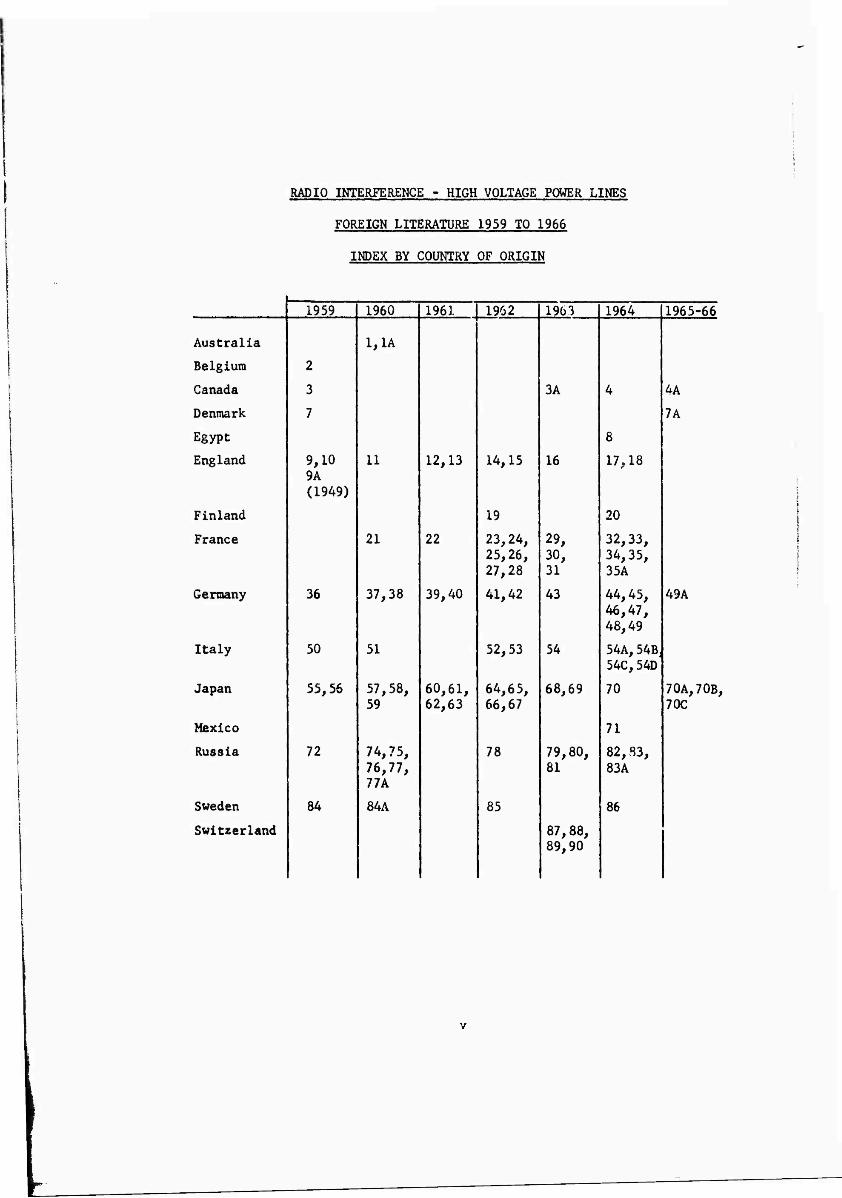
RADIO INTERFERENCE - HIGH VOLTAGE POWER LINES
FOREIGN LITERATURE 1959 TO 1966
INDEX BY COUNTRY OF ORIGIN
1959 1960 1961 1962 1963 1964 1965-66
Australia 1,1A
Belgium 2
Canada 3 3A 4 4A
Denmark 7 7A
Egypt 8
England 9,10 9A (1949)
11 12,13 14,15 16 17,18
Finland 19 20
France 21 22 23,24, 25,26, 27,28
29, 30, 31
32,33, 34,35, 35A
Germany 36 37,38 39,40 41,42 43 44,45, 46,47, 48,49
49A
Italy 50 51 52,53 54 54A,54B, 54C,54D
Japan 55,56 57,58, 59
60,61, 62,63
64,65, 66,67
68,69 70 70A,70B, 70C
Mexico 71
Russia 72 74,75, 76,77, 77A
78 79,80, 81
82,83, 83A
Sweden 84 84A 85 86
Switzerland 87,88, 89,90
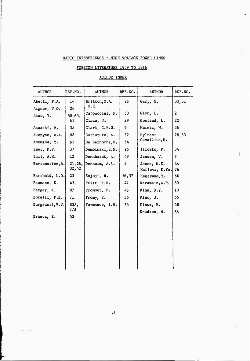
RADIO INTERFERENCE - HIGH VOLTAGE POWER LINES
FOREIGN LITERATURE 1959 TO 1966
AUTHOR INDEX
AUTHOR REF.NO. AUTHOR REF.NO. AUTHOR REF.NO.
Abetti, P.A. U: Britton,G.A. 16 Gary, G. 30,31
Aigner, V.O, 24 j C.R.
Akao, Y. 58,63, Cappuccini, F. 50 Gion, L. 2
65 Clade, J. 29 Cos land, L. 22
Akazaki, M, 3A Clark, C.H.W. 9 Heintz, W, 36
Akopyan, A.A. 82 Curcuruto, A. 52 Hylten- 28,33
Amemiya, Y. 61 De Bemochi,C. 54 Cavallius,N.
Baer, K.V. 37 Dembinskl,E.M. 15 Iliceto, F, 34
Ball, A.H. 12 Dennhardt, A. 49 Jensen, V. 7
Bartenstien,R. 21,26, Denholm, A.S. 3 Jones, D.E. 4A 32,42 Kafieva, K.Ya. 76
Baithold, L.O. 23 Enjoji, H. 56,57 Kageyama,Y. 60
Baumann, E. 43 Feist, K.H. 47 Karamzin,A.P, 80
Berger, K, 87 Frommer, E. 46 King, S.Y. 10
Borelli, F.B. 71 Fromy, E, 35 Kino, J. 55
Burgsdorf,V.V. 83A, Furmanov, I.M. 75 Klewe, H. 48 Ilk
Knudson, N. 86 Brasca, E. 53
vi

RADIO INTEHFERENCE - HIGH VOLTAGE POUER LINES
FOREIGN LITERATURE 1959 TO 1966
AUTHOR INDEX
AUTHOR REF.NO. AUTHOR REF.NO. AUTHOR REF.NO.
Kohoutova,D. 6 Poltier,L. 89 Varshney,M.P. 17
Larsson, 0. 85 Popkov,V.I. 5,81 Venchkovskii, 77
Larsson, N. 20 Rogers,E.G. 11 L.B.
Lorenz, H. 38 Sajonz,J. 39,40 Warner, A. 49A
Malakhov,A.M. 72 Sarapkin,V.V. 79 Whitehead,S. 9A
Meister, E, 88, 90
Saruyama,Y. 70A Witt, H. 84A
Morris, R.M.
Orlov, V.N.
4
78
Sawada, V. 64,67, 70C
Yamada, T. 59, 70
Ortloff, M, 41 Sato, Y, 62 Yainaguti,T. 68
Paris, L. 51 Sforzini,M. 54A,B, Zaazou, A. 8
Paimoeuf,M. 25 C&D
Pedersen, A, 7A Smirnov,B.V. 74
Pellissier.R, 27 Sporn, Ph. 21A,35A
Perelman,L.S. 83 Takesu,N. 66,69
Personen,A.J. 19 Thebridge,F.A. 1
Petterson,G.A, 84 Thomas,D.R.W. 13
Pfaler,E.Von 44, Thornton,J.G. 1A 45
Udo, T. 70B
Vll

to vD Ox
H
0*1 m ON
s
CO
• < Hi
i-3
w % sa n\ H Q J «£ O KI > ol
O r-l 00 18
r«. fH r*»
«n en •4" «n co m
<r ^ ^ 1 o « ^o 2 H
p r* O H H •N o <i| W ro P*l 2 ro UJ 51 ? •N J5 O 1 H |rH M H
IQ t> HJ fe
^ <
•KrH CM m «.co in <: ^
•vCO vD O 00 CO
•>0N fH O •vl1 m CM r>.
•* ^ < pa »n rH <t o oo n m fN.
•» »s ^ «s CM <3- r>. <!
•^r^ en o oo •* ^r»«.
%| rH ON CO »v Ml •» ^ «kO •jo r>. o> "T
oil n oo r^ m
00
VO in <
«n oo
CM r-4
T3
< St -d- otf s h. B g en 00 (* o
otT S 1 fc, N] M hn > H CM O [ », Jz; < •v Crf
00 O H ON O Im o CO CM U|
oo *< in <r ^d-
•v «xOO « sr •»
• CM m <; HI % «i en
•IrH CO * oj oo cn oo
a ttj 1
9 ^!l g N c; M rn z a: u
Q 1 M 5 §1
o
-J- vO i-H CM
•s •» CM SO vD n
•» < r-> m CM en
•s •« CM in CM i-i
ON
•< »v in »V •» •, < *> rv r« m vo r^ •. «»o <n so »s r*» u* •vr«*cnt-ifooooÄ<
•v«\vo •»•kincMr^ •»•M-i o <n m m rv. •» ^ «^m CM •* CM vo •» ^rs, CM en < <!■ oo o
•»•^r^^J •»r>»»-io •»•sCO O r»» m «^ <• % «»Oi m r»* •» rs.<n ^inrxoio «»cnrHcn
. •» «s<! «^ »»CM •4' PQ •* ■»'^ <I O M >t VO Vj" ^ -.^ < fK -^r-l vDcnoo<ncMf^.oNinr>.oooocM
CO ^ o r»* M vO ss H •k o s w o\ M 00 CO 3 H •% u J < oo H M H M pa H < V5 ^»d- cs b <
m m H4 r-l CxJ • r-l •< H w CM 2 H ^< < 2 * M CM rx en H M ON ►J -^ ai I-. 00 COi iJ CO
CO »-1 «««>
£ Is •kVO 00 en KM ^^ -k
H JU o CM en
9 oi ON m,-t
•kCM •* O H m r^. <n
w S •^m oo m 2 |H h* rs« en ON
CM
m r-s
en
3 •k
m ON
•k
CM <!■
•k
oo oil
o ON
■k
m m
•k
en
a
Ida
tn
en
s a OIH^
H
en in
li
•k »k «k r*. oo ON €M fN. en . ..
"k "k ^ Q r-i «4 en «T CM •4' CM m
S ^ c4 ■k «K »k "k >- u.
ON CM en en oi CO m en oo <n O •1 g <K «k «k «k ä H en ON m r«* JC » M •4 rv sj- r*» H ad J
•k »k «k Q en en in >T vt oo vo in
•» «^ «k «k
--« -a" O r*» CM -4 so r^
■k «k ^ •« pa r«» vO >o en O CM Q0 en CM rs.
< m en
•V
00
oo •k
CM en
Vlil

6 S
w
w
B
oi
s g H
CJ
ä o fe in w
eg o> »»00 VO 00 r-4 •»
r>. vo »if-« vO ""> O K
•» ^CM PQ
fo Lo en m oo «^n »^
< ^\o r«. o to vo co r>» r>.
o
vO * vO
Cx3|in
JH H1 CJ • Q tA
s 2 Q 2S o O M X o H M Ü oi H < 2? 2 CJ M H
U 02 to o O 5g S | C)
H g o oi r^» 05 i < e
O W ^ O vO Oi t*» S h 2 o <!■ O vO ^ 5 vO X u
< m
oo * ^<
vo r>. oo r«.
to
CO < tt! <r Jz sO O ^ s w rH H
3 -. u o < M ON D z rn >4
Pi ",• i M 00 fe S w ^ D O oo O o r^. O o 00 o < vO O
st r^ 0> •* eg <}- m en
•» »v «v «v Ov O ON 00 sn «/ rn -^ ^ % •» in
<t o CM co m oo \o m vo sr
g
o>
o vO
in
00
00
vO U <o
m
vO o
00
ix

vO
OX
O M
s
XI Mi
3
<3
Ml Ü <
s o H ->
S5 M H o o ^ > H H H osi U £ U u w 5 § i CO H ä §1
m oo oo -.
%«n as so r> ^
CM ^
•iOO «s H «siA •\\0 ->
a: oo r>*
•V O» rH ON -4- •V
NO •» 00 •s vO »A m f-i •k •* •> o
^ oo >* en oo •> •» •» f>. m r«. ro CO 00 ^
•V •» < as o\ rH m • »A ^ <n <r •* •> •svO o\ 00 fs» * CN CM m m
w
>
IS 1 N'
o\
«n
oo
J\0 I NO
8:
lOs
. ■■"V::=%r<^aP,3:*v^^^ *
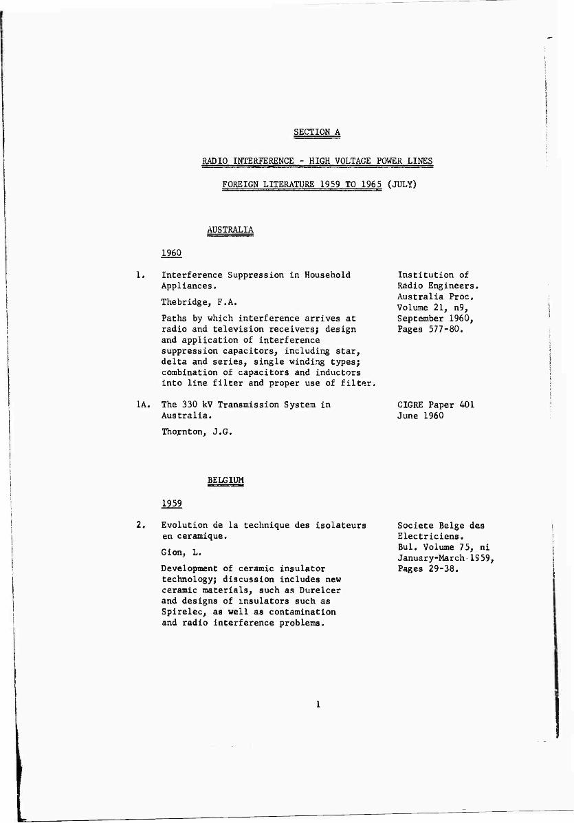
SECTION A
RADIO INTERFERENCE - HIGH VOLTAGE POWER LINES
FOREIGN LITERATURE 1959 TO 1965 (JULY)
AUSTRALIA
1960
1* Interference Suppression in Household Appliances.
Thebridge, F.A.
Paths by which interference arrives at radio and television receivers; design and application of interference suppression capacitors, including star, delta and series, single winding types; combination of capacitors and inductors into line filter and proper use of filter.
1A. The 330 kV Transmission System in Australia.
Thornton, J.G.
Institution of Radio Engineers. Australia Proc, Volume 21, n9, September 1960, Pages 577-80.
CIGRE Paper 401 June 1960
BELGIUM
1959
2, Evolution de la technique des isolateurs en ceramique.
Gion, L.
Development of ceramic insulator technology; discussion includes new ceramic materials, such as Durelcer and designs of insulators such as Spirelec, as well as contamination and radio interference problems.
Societe Beige des Electriciens. Bui, Volume 75, ni January-March 1S59, Pages 29-38.

CANADA
1959
3. Radio Noise Testing of High Voltage Line Equipment.
Denholm, A.S.
Facilities for noise testing at National Research Laboratories and methods adopted to minimize interference from test equipment itself; two simple noise measuring circuits which compensate for stray and coupling capacitance.
Engineering Institute of Canada. Trans. Volume 3, No. 1, April 1959, Pages 13-17,
1963
3A. Corona Phenomena from Water Drops on Smooth Conductors Under High Direct Voltage.
Akazaki, M.
National Research Council of Canada. Ottawa, Canada, November 1963.
1964
4. Work of the National Research Council of Canada on Corona and Radio Interference in High Voltage B.C. Systems.
Morris, R.M.
An extended summary is given of two reports issued by the councils Radio and Electrical Eng. Division. Corona loss measurements were made on a single steel-cased aluminum conductor of 1.108 in. diameter and on a twin conductor bundle of the same size, with 18 inch spacing. An inner insulated wire in the conductor enabled conductor losses to be measured independent of other losses. Voltage increment tests were made in steps of 50 kV from 20 to 500 kV d.c, positive and negative, and during constant weather conditions. Losses were also measured with the lines at constant voltage in varying weather conditions. Radio interference characteristics were measured with the
Direct Current (GB), Volume 9, No. 1, Pages 26-34, (February 1964).

lines at 300 to 500 kV d.c, under corona excitation, and under excitation by an oscillator, measurements were made at 0.2 to 10 Mc/s. The results are shown graphically. It was found that corona losses from each conductor configuration were higher under negative than under positive voltage. Only positive conductors produced radio interference in the frequency range studied.
CZECHOSLOVAKIA
1961
5. Otazky potlacorani radioveho nuseni zpusobereho Koronon,
Popkov, V.l.
Problems of suppression of radio disturbances caused by corona; radio interference carried by direct and alternating current, special features of disturbances in frequency range from 150 to 8800 Kc/s and their dependence on form of corona; most advantageous counter measures are seen to be special coating of conductor for negative corona and application of screening wires of small diameter for positive corona (English summary).
Elektrotechnicky Obzor, Volume 50, No. 4, April 1961, Pages 185-191.
6, Measurement of Corona Losses and Determination of their Yearly Average on VHV Lines.
Kohoutova, D.
Describes 400 kV experimental line in Bechovice, consisting of bundled conductors of the type Al Fe and of 350 mm cross section, results of corona loss measurement with an analysis of the climate conditions in the northern branch of Czechoslovakias 400 kV line are given. A relationship is shown for the calculation of the yearly corona loss.
Elektrotechnicky Obzor (Czechoslovakia), Volume 52, No. 6, Pages 287-91 (1961) In Czech.

DENMARK
1959
7. Radio Interference in the VHF Range.
Jensen, V.
Analysis of impulsive interfereice in VHF range, where in particular TV reception is exposed to disturbance by motorcar ignition interference and commutator interference from electrical appliances; methods of measuring interference voltages and interference fields originating from electrical machinery, results of laboratory measurements of various VHF interference suppressing components are reported and some methods of vhf commutator interference suppressions are stated.
Teleteknik (English Ed.) Volume 3, No. 1, 1959, Pages 1-17.
EGYPT
1964
8. Radio Noise due to Insulator Corona, Effect of Atmosphere Humidity and Other Factors.
Zaazou, A.
Radio noise due to corona discharges on suspension insulators is studied as influenced by atmospheric humidity, insulator—surface polution and harmonic contents in the alternating voltage wave applied across the insulator. The radio- noite level is also measured under direct- volcage conditions. The tests were carried out in humidities between 10 and 38 mg/M** at temperatures, between 150C and 380C. Alternating voltages up to 45 kV are used with harmonic contents up to 40%, and direct voltages up to 70 kV are applied. The radio noise level is found to increase with the air humidity and decrease if the insulator is kept in a humid atmosphere for
Proc. Inst. Elect. Engr. (GB), Volume III, No. 5, Pages 959-66 (May 19C/:).
jüiliWi^WIM*1»*^

sometime. The noise level with alternating voltages is found to be considerably higher than that with direct voltages of the same amplitude. It is found to be still higher if the alternating voltage wave contains third harmonic so as to be double-humped. The cement binding the metal cap and pin to the porcelain is found to be main source of radio noise when the insulator is under corona discharge.
ENGLAND
1959
9. Radio Interference from HV Insulators
Clark, C.H.W.
Explains the mechanism of interference generation by high voltage insulators and the effect of insulator design on radio interference. The measurement of interference is considered and methods of overcoming the difficulties involved are discussed.
Electrical Review Volume 165, No. 11, Pages 491-7, October 23, 1959.
10. Electric Field Near Bundle Conductors
King, S.Y.
Analysis deals with single phase lines with bundles of two, three of four conductors, but it can be extended to cover any number of conductors in bundle: for 3 phase lines, resultant field can be found by principle of superposition when fields due to two or other phases are taken into consideration, formulas giving potential gradient at any point on conductor surface.
Institution of Electrical Engineers Proceedings, Volume 106, pt. C, No. 10, (Monograph N338) September 1959, Pages 200-6.

ENGLAND
1960
11, Gaseous Discharge Phenomena in Proc. Institution High-Voltage d.c. Cable Dielectrics. of Electrical
„ „ Engineers. 1960, R0Sers' E-C- lO^A, F. 241. Considerations of the short-time electric strength and of the conductivity/temperature stress relationships show that both impregnated paper and polythene are likely to be satisfactory dielectrics for use in HVDC cables. From a.c. experience, however, it is known that polythene in particular is very vulnerable to damage caused by discharges in gas-filled cavities, and an assessment of the importance of this mode of deterioration under d,c. conditions is therefore necessary.
Calculations have been made of the repetition rate of discharges in a gas-filled cavity in a dielectric subjected to a d.c. stress, since this is clearly a decisive factor determining the rate of deterioration. The repetition rate is shown to be a maximum when the surface conductivity of the dielectric is zero. Direct measurements of the repetition rate of discharges are described, and the measured rates are shown to be consistent with the calculated maximum rates. The effects of ripple voltages and polarity reversals are considered.
From the predicted discharge repetition rates and from the results of accelerated life tests on samples containing cavities, a rough estimate of the effect of discharges on the probable life of an HV d.c. cable dielectric can be made. Polythene was selected as the example for study on account of its known vulnerability to discharges, and it is shown that with this material, discharge damage is unlikely to be a serious problem under d.c. conditions.

provided that ripple voltages are not excessive and that very frequent reversals of polarity can be avoided.
1961
12. Radio Interference from Ignition Systems.
Ball, A. H.
Comparison of American, German and British measuring equipment, techniques and limits, test conditions specified in various countries and limits of ignition interference recommended or statutory in countries concerned. Paper 3550E.
Inst. of Electrical Engrs. Proc, Volume 108, pt. B. (Electronic and Communication Eng.) No. 39, May 1961, Pages 273-8. See also Brit. Elec. and Allied Industries Research Assn.-Tech. Report M/T138, 1960, Page 15, Supp. Plate.
1961
13. Probabilities of Interference with Mobile Field Radio Derived from Field Strength Survey at 59 Mc/s.
Thomas, D.R.W.
Experimental investigation of common and iromediately-adjacent-channel interference area based on field- strength survey over flat and hilly country, graphs on interference probability for practical use, 25 refs. Paper 3472E.
Inst. Electrical Engr.-Proc, Volume 108, pt. B. (Electronic and Communication Eng.) No. 39, May 1961, Pages 264-72.
1962
14. System Engineering Problems in EHV Transmission, Corona Loss, Radio Noise and Lightning Performance.
Abetti, P.A.
Corona loss, radio noise and lightning performance of EHV transmission lines are discussed from the system engineering, viewpoint. Examples are given of methods employed to evaluate the significance of these factors in system design. Recent
CEGB Engr, Conference on Gas Discharges and the Electricity Supply Industry, Leather- head, 1962 (see abstract 3511 of 1963), Pages 157-72.
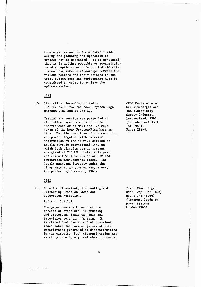
knowledge, gained in these three fields during the planning and operation of prolect EHV is presented. It is concluded, that it is neither possible or economically sound to optimize each factor individually. Instead the interrelationships between the various factors and their effects on the total system cost and performance must be considered in order to achieve, the optimum system.
1962
15. Statistical Recording of Radio Interference from the Monk Fryston-High Marnham Line Run at 275 kV.
Preliminary results are presented of statistical measurements of radio interference at 55 Mc/s and 1,5 Mc/s taken of the Monk Fryston-High Marnham line. Details are given of the measuring equipment, together with relevant information or* the 55-mile stretch of double circuit operational line on which both circuits are at present energized at 275 kV. Later this year one circuit will be run at 400 kV and comparison measurements taken. The levels measured directly under the linen ^»ere at no time excessive over the period May-December, 1961.
CEGB Conference on Gas Discharges and the Electricity Supply Industry, Leatherhead, 1962 (See abstract 3511 of 1963),
Pages 282-8.
1962
16. Effect of Transient, Fluctuating and Distorting Loads on Radio and Television Reception.
Britton, G.A.C.R.
The paper deals with each of the effects of transient, fluctuating and distorting loads on radio and television reception in turn. It is stated that the effect of transient loads takes the form of pulses of r.f. interference generated at discontinuities in the circuit. Such discontinuities may exist by intent, e.g. switches, contacts.
Inst. Elec. Engr. Conf. Rep. Ser. (GB) No. 8 3-5 (1964) (Abnormal loads on power systems London 1963).

contactors, and thermostats, or fortuitously by the physical nature of circuit components, e.g. commutators and brusher, gaseous discharge devices, surface leakage across high-voltage insulators or sliding contacts. The relative importance of the various kinds of transient interference is indicated by reference to the totals of complaints of interference received by the post office. Methods of measuring, assessing and suppressing the interference are touched on, and recommended limits are mentioned.
The effects of fluctuating loads on radio and television reception are seldom of great importance; they are, however, mentioned briefly. Finally the effect of distorting loads is considered, the example of interest being the mercury arc rectifier, which generates harmonics that may produce audio hum .n radio reception and distortion of a television picture.
1963
17. Balanced Corona Performance for Asymmetrical Three Phase Overhead Power Transmission Lines.
Varshney, M.P.
A.c. transmissions of larger blocks of power over larger distances has resulted in the use of progressively higher voltages, and the type of line conductors to be used then acquires increasing importance. For extra high voltage transmissions lines corona considerations result in the use of expanded AC SR; hollow copper conductors, or bundle conductors. For one conductor per phase, when corona considerations are the deciding design features, it may be desirable to design each phase separately, particularly for the conmonly used flat horizontal configuration so as to bring the surface voltage gradient for each conductor down to the allowable value but no further.
International J. Elect. Eng. Education (GB), Volume 1, No. 3, Pages 345-9, March 1964.

Approximate expressions for surface voltage gradient are derived for the flat horizontal configuration.
1964
18. 800 kV Transmission Line Research at Leatherhead.
Experimental transmissions line was installed to enable Central Electricity Research Labs, to study insulators, fittings and conductors up to equivalent of 800 kV, 3 phase, continuous recording will be made of corona power loss and radio and TV interference; for this purpose statistical radio-interference recorder was developed; instrumentation also includes automatic corona loss bridge and data logger.
Engineer, Volume 217, No. 5653, May 29, 19b4, Pages 949-50.
FINLAND
1962
19. Intersections Between Telecommunication Lines and Power Lines, with Reference to the Earth Fault Potential,
Pesonen, A.J-
The neutrals of the 110 kV, 220 kV and 400 kV systems in Finland are directly earthed. The earth fault currents are assumed to range between 0.5 and 3 kA. The degree of interference with teieconmunlcation installations has been worked out.
Kraft u. Ljus (Finland), Volume 35, No. 11, Pages 292-6, (November 1962), In Swedish.
1964
20. Measurements of Corona Losses due to Hoar Frost and Water Precipitation on 400 kV. Operating Lines in Finland with special reference to Estimation of Hoar Frost Corona Losses Based on Meterologlcal data.
Conf. Intern. Grands Reseaux Elect. (CIGRS), France, 1964, Paper 409, Page 13.
10

Larsson, N.
Summarizes the measurements of corona losses on operating 400 kV lines in Finland made during three successive winter periods. The effect of the line current upon the layer which has been formed on the conductors has also been investigated. Finally a method is presented, which could be applied in estimating the winter corona losses on lines that are going to be constructed in the areas where hoar frost is likely to occur.
FRANCE
1960
21, Predetermination of the High-Frequency Level of High Voltage Transmission Lines.
Bartenstein, R.
The results gained by the 400 kV test station at Rheinau have made possible a fundamental description of the nature of interference phenomena. Beginning with the high-voltage transmission line as a source of Radio Interference, a definition is given of the interference quantity which makes it possible to describe the nature of interference with the aid of an equivalent circuit diagram. The factors influencing this interference quantity are also studied, a distinction being made between those which can be controlled by varying the line configuration and those which cannot be readily controlled. The measurement of these variables is described. From all investigations so far carried out it can be seen that there is a general correlation between the surface field gradient and interference field intensity at least for bundled conductors. Once the correlation between the surface field gradient and interference field intensity and the equivalent circuit diagram for interference phenomena is known the line RI level may be calculated.
Conf. Intern, Grands Rese^ux Elect. (CIGRE) (France) 1960, Pages 409-411.
11

FRANCE
1960
21A. Report on the Work of Study Coramittee No. 9 on Extra-High Voltage A.C. Transmission,
Sporn, Ph.
Discusses economic aspects of Extra-High Voltage transmission. Fault statistics RI measuring in different countries with the same meter.
1961
22. Report on the work of Study Committee No. 11 Radio and Telephone Interference.
Cosland, L.
Study committee No. 11 met in Paris on June 1960 and in Arizona in April 1961. This report notes the principal matters discussed by the conmittee, and presents, in appendices, preliminary information on some of the topics of major interest at present which has been contributed by members of the comnittee.
CIGRE Paper 416, June 1960
(CIGRE) France, Paper 329, Paae 14, (1962),
1962
23. Some Important Assumptions in Calculation of Radio Noise Levels of EHV Lines.
Barthold, L.O.
Extension of prior analytical methods of predicting radio noise levels caused by random corona discharges on ehv transmission lines, evaluation of noise generation on power spectral density basis, and propagation and treatment of corona pulses by means of eigen valr.e analysis, effects of line length.
Conference Int. des Grand's Reseaux Electrique a Haute Tension 19th May 16-26, 1962, Cr No. 303, Page 12, CIGRE,
12
Z*& 0äk *■ ^T^

FRANCE
24. Corona Detection in Transformers.
Aigner, V.O.
Report on behalf of int. study committee, necessity of standardization or at least gaging of different measuring instruments and their coupling on same base; inner corona and its possible effects; methods of testing corona intensity, corona- behavior and life span of transformers; permissible corona for transformers, test methods.
Conference Int,- des Grands Reseaux Electrique on Haute Tension 19th, May 16-26, 1962, CRN 145, Page 20, CIGRE.
25. Special Report for Group 35 (Radio and Telephone Interference).
Paimoeuf, M.
Conf. Int. Grand Reseaux Elect. (CIGRE) (France) Spec. Report Group 35, Page 4.
1962
26. Radio Interference on Bundle Conductor Lines.
Bartenstein, R.
Gives a survey of Radio Interference Measurements on bundle conductors carried out on test and operating lines, states the results gained to date and makes recommendations for further investigations.
CEGB Conference on Gas Discharges and the Electricity Supply Industry Leatherhead, 1962, (See abstract 3511 of 1963),
Pages 307-10.
13

FRANCE
1962
27. Basic Principles for Radio Noise Calculations on EHV Transmission Lines.
Pelissier, R.
The present state of the theory of generation and the propagation of RI on EHV lines is reviewed. Certain refinements are put forward and the consequences of their introduction into the calculations are considered in detail. An explanation is suggested for the saturation effect of RI from a conductor in intense corona, together with suggestions for further investigations.
CEGB Conference on Gas Discharges and the Electricity Supply Industry, Leatherhead, 1962 (See abstract 3511 of 1963), Pages 274-81.
28. Radio Noise from High-Voltage Direct Current Systems.
Hylten-Cavallius, K.
The ignition of the valves of a HV, DC converter station generates radio noise. In the report some important aspects of this generation and of different means for its reductior are given.
CEGB Conference ^n Gas Discharges and the Electricity Supply Industry, Leatherhead, 1962 See abstract 3511 m 1963),
Pages 295-306.
1963
29. Etude des perturbations radioelectriques engcndries par des convertisseurs statiques a haute tension.
Clade, J.
Study of radio interference caused by HV static converters; meaFurements are reported, made at Echinghcn converte station, at French terminal of cross channel cable, reduction of interference to Relatively negligible levels was accomplished by means parallel and series connected RC filter network in substation circuit.
Rev. Gen. de l^lectricite Volume 72, No. 6, June 1963, Pages 343-57.
1A
FRANCE
30. Contribution to the Study of Radiophonic Disturbances Produced by MV Lines.
Gary, G.
While the phenomena in rigid and suspension insulators are of different origin, the mathematical expressions and the test methods are the same. Experiments give the spectral distribution of the perturbance current up to 50 Mc/s. The effect of propagation conditions at different frequencies is discussed and a simplified equation is derived. Field measurements give higher value than those taken in the laboratory and further studies of these differences are projected.
31. Constribution a l^tude des perturbations radiophoniques engendties par les lignes a mayenne tension.
Gary, G.
Radio interference produced by medium voltage lines, it is shown that same expressions and same test methods can be applied in investigations of interference phenomena on rigid and suspension insulators, respectively, through origin of interference on 2 insulator types of different origin) Spectral distribution of interference Current up to 50 Mc/s is derived, along with simplified expression.
Revue Generale de 'lElectricite, Volume 72, No, 10, Pages 503-18. (October 1963) In French,
Revue Generale de Electricite, Volume 72, No. 10, October 1963, Pages 503-18,
1964
32. Attenuation Measurements on a High Voltage Overhead Line.
Bartenstein, R.
The calculation of HF interference on overhead lines presupposes a knowledge of the transmission characteristics of the line. During the construction of a 110 kV overhead line with 240/40 (21.7 ram diameter) asc conductor in a triangular configuration
Conf. Int. Grands Reseaux Elect, (CIGRE) (France) 1964, Paper 419, Page 21.
15

FRANCE
it was possible to measure the frequency-dependent transmission characteristics of the line in different states of construction. These measurements permitted the calculated transmission characteristics to be checked and corrected if necessary. The measurements were at first carried out with only one phase conductor in place. Subsequently the two other conductors of the three-phase system were installed and the transmission characteristics measured of the three different transmission circuits (modes) for HF interference currents which are largely independent of each other. For an earth conductivity of 3.8 x 10*■ v/cm and 500 kc/s an attenuation of 1.7 dB/km was obtained for the mode 3 (with earth return) and of 0.10 dß/km and 0.12 dB/km for the balanced modes 1 and 2 which are symmetrical to earth. For the single-phase line with earth return an attenuation of 0.96 dB/km was measured. Other attenuation values are compiled in a table.
33. Corona Losses, Radio Interference and Conf. Int. Grands Insulator Requirements for High Voltage R. Elect. (CIGRE) DC Lines, Studies Regarding Insulator France 1964, Interference for Frequencies Between Paper 407, Page 21, 30-1500 Mc/s.
Hylten-Cavallius, N.
Systematic measurements of monopolar HV DC corona losses up to 1 mv and bipolar up to + 350 kV are compared with calculations and reasonable agreement is found. The variations of losses with weather, conductor diameter, height and spacing is illustrated. Measurements of radio interference from the line have been carried out simultaneously with mea^rement of corona losses. The nominal conductor gradient appears to determine the radio interference at least for the range of practical interest.
16
L

FRANCE
Studies have been made regarding radio interference from line insulators for frequencies betweer 30-1500 Mc/s. Some aspects are given on the insulation of DC lines and choice of DC insulators and the result of long-terra pollution test is given.
34. Some Design Aspects of Harmonic Filters for HV DC Transmission Systems.
Iliceto, F.
With the advent of high power converters for HV DC transmission systems, little attention was paid to harmonics in electrical power networks, because in general, harmonic levels were found to be acceptably low. Installations of HV DC converters, however, are large relative to the network to which they are connected and it becomes necessary to install, filters to reduce harmonic currents and voltages produced by them. The paper is divided into two parts. The first gives a discussion of harmonic penetration in a network, and methods of defining and specifying harmonic disturbance. The second gives a description of filter designs for a particular installation and their design basis.
35. Considerations generales sur les pertubatlons radioelectriques et les possibilites de deparasitage a la source.
Fromy, E.
Radio-frequency interferences and possibilities of their elimination at source; origins of various types of interference are systematically investigated and methods and arrangements proposed for measuring influence on electric lines and line models, general considerations are presented for how to use results of study for interference suppression.
Conf. Int. Grands R. Elect. (CIGRE) (France) 1964 Paper 405, Page 35.
Revue generale de 'lElectricite, Volume 73, No. 6, June 1964, Pages 353-64.
17

FRANCE
35A. Progress Report of Study Committee No. 9 on Extra-High Voltage AC Transmissions.
Sporn^ Ph.
Poses question of limitation of radio disturbances produced by power transmission lines.
In view of present knowledge, it appears impossible to propose, under any form whatsoever, a limitation of stray fields in the vicinity of power transmission lines. At present, the only effective method (increase of conductor cross-sections) would result in such an increase in the cost of lines that their construction would become impossible. Detailed mathematical treatment of propagation of HF on overhead lines.
CIGPvE, Paper 420, June 1964, RI Section.
GERMANY
1959
36. Untersuchung des hochfreqprenten Spektnums periodischer Enthdungen.
Heintz, W.
Study of HF spectrum of periodic discharges. Experimental and theoretical analysis of discharge pulses,HV transmission line corona, contributing to interference in HF communication.
Zeit fuer Angewondte Physik, Volume 11, No. 2, February 1959, Pages 51-7.
1960
37. Untesuchungen ueber Glimmentladungen an Armaturen fuer 110 kV Freileitungen.
Baer, K.W.
Corona discharge on fittings of 110 kV overhead lines; tests carried out on conventionally used and recently introduced new type of fittings, in interest of radio interference suppression.
Elektrizitatswirt- schaft. Volume 59, No, 5, March 5, 1960 Pages 126-30.
10

GERMANY
1960
38, An Instrument for Measurement of Interference Field Strength in the Frequency Range 30 to 225 Mc/s.
Lorenz, il.
A general description of the FMG2 instrument developed by VEB Funkwerk, Dresden, which operates as a calibrated heterodyne receiver. A block diagram shows the arrangements of the various units. The total frequency range is covered on 8 scales and the uncertainty of the frequency indication is < + 17», while the frequency constancy is better than 1 x 10*^ for 60 min. after a 5 min. warm-up period, a quartz controlled oscillator being used for the second mixer stage. A detailed account is given of instrument working and calibration.
Nachtichtentechnik, Volume 10, Pages 23-b, (January 1960) In German.
1961
39. Interference between Power Lines and Telecommunications Installations.
Sajonz, J.
A comprehensive paper, dealing, on restricted space, with risk of danger and noise disturbances, electric and magnetic induction, internal impedance of an induced line for both forms of induction, calculation of longitudinal induced voltages, allowing for screening effects and protective measures against dangerous voltages and noise.
40, Die Beeinflussung von Schwachrtromanlagen durch Starkstromleitungen.
Sajonz, J.
Frequenz (Germany) Volume 15, No. 3, Pages 79-87, (March 1961) In German.
Frequenz, Volume 15, No. 3, March 1961, Pages 79-87.
Influence of low current Installations by high current transmission lines, capacitive and inductive influences, due to rigid grounding of neutral point, increasing adoption of electric traction, etc.
19

GERMANY
1962
41. High-Frequency Mains Filters for Eiectromagnetically Screened Rooms and High Voltage Halls.
Ortioff, M.
The increasing number of powerful transmitters and electromagnetic disturbances necessitates the introduction of totally enclosed mains filters of improved design in the mains supply of screened rooms. Commercially available mains filters have 60 dB attenuation in the frequency range from 150 Kc/s to 30 Mc/s which can be extended to 100 Db. Attenuation up to 1 Gc/s. Construction of a typical 6 kV 200 A wide-band filter is shown and several others, consisting of double or triple ir filters are described.
Elektrotech Z. (ETZ) B (Germany), Volume 14, No. 23, Pages 630-3 (November 12, 1962) In German.
1962
42, Continuous Measurements of High-Frequency Interference Level of HV Transmission-Lines and Their Statistic Evaluations.
Bartenstien, R.
Measurements carried out on 344 km, 3Ö0 kV transmission (West Germany), line; existing conception that investigations of different parameters are best to be carried out on short test line, has been confirmed.
Conference Int. des Grands Reseaux Electriques a Haute Tension 19th, May 16-26, 1962 CR, No. ^09, Page 15.
1963
43. Corona Pulses, RF Spectra and Their Relation to Non-Ionizing Collision Cross-Sections.
Bauinann, E.
Since the voltage of the German grid system has been raised to 330 kV, corona was investigated in 400 kV test plants
CEG3 Conference on Gas Discharges and the Electricity Supply Industry, Leatherhead, 1962, (See abstract 3511 of 1963), Pages 23^-49.
20

GERMANY
and in laboratories. A point of great importance for the power supply is the RF interference spectrum which is caused by corona discharges on outdoor lines. The corona discharge pulses propagate along the lines and interfere with the transmissions of measurement and control signals. The RF interference currents in the conductors also cause electromagnetic disturbance field strength close to high voltage lines. The intensity and frequency range of these interference spectra should be calculated from laboratory tests or from experiments with outdoor test lines. Therefore, to permit such calculations, correct results must be used in the equations. In this paper the relation between the interference spectrum and the movements of the charge carriers in the field is shown, in the case of short lines with corona discharges. There follows a correlation between the frequency spectrum and the effective non-ionizing collision cross-section which is basically important for all further physical and technical experiments.
1964
44, The Predetermination of HF Interference Elektrotech Z (ETZ) Caused by High Voltage Lines. A (Germany),
Von Pfaler, C.E. ^oiurac,"'tNo- 9'
'. Pages 261-6 A mathematical article in which the (May 1, 1964), relationship between the field strength In German. close to a three-phase line and the interference current generated per unit length of conductor due to corona discharge, which can be measured on a short single-phase line is derived.
21

GERMANY
45.
46.
47.
1964
Die Vorauskrechnung der von Hochspannungsleitungen venursachten hochfrequenten Stoenungen.
Pfaler, E. von
Precalculation of HF interference by hv lines, quantitative relationship is given between interference current caused by corona discharges in unit length of single phase line.
Possible types of Interference with Radio Direction-Finding Installations by Medium and High Voltage Power Systems.
Frommer, E,
Deals with investigations concerning the minimum separation between an existing radio direction finder and a planned medium voltage line. Interference carries in two ways: The power line can be aa active source of radiation, or it can re-radiate, as a secondary source, signals sent from the transmitter and, hence, disturb the accuracy of the direction. Both effects, are considered separately; it has been found that in the case in question, the indirect effect was decisive dictating a minimum separation of approximately 30U meters.
Parameters of Three-Phase High Voltage Systems Related to Inductive and Conductive Coupling with Telecommunications Circuits.
Feist, K.H,
Investigates the significance of the various parameters which determine voltages in telecommunications circuits induced from parallel power lines, or impressed, by conductive coupling, when the telecoiranunication installation approaches earthing points of high voltage systems. Discussed are zero sequence currents, particularly in networks with earthed
L.U (Ed. A) Volume 85, No. 9, May 1, 1964, Pages 261-2,
Nashrichtentech, Z. (NTZ) (Germany) Volume 17, No. 9, Pages 468-71, (September 1964). In German.
Elektrotech Z (ETZ) A (Germany), Volume 85, No. 20, Pages 641-6, (October 1, 1964). In German.
22

GERMANY
neutral, double-three-phase lines, variation of screening factors with current which can make unreliable, extrapolation of measurements made with small currents, effects in cable networks and screening by earth wires. Measurements under different conditions are explained in detail.
4ö.
A9.
Notes on the History of Induetivt Interference Between Power Lines and Telecommunication Lines.
Kiewe, H.
A brief historical survey, beginning with disturbances by the earliest railways, and dealing with electric induction, acoustic shocks, ac and dc railways, particularly if rectifiers are involved, mutual inductance between lines with earth return, measurement of noise due to harmonics, unbalance of lines and equipment, as well as with international cooperation, international and national rules and directives, and the limits for dangerous and disturbing voltages. The development of new power and telecommunication techniques leads time and again to new problems which should be resolved by cooperation between the two sides.
Elektrotech L (ETZ) A (Germany), Volume ö5| No, 20, Pages 625-3Ü, (October 2, 196A). In German.
Further Development of Electrical Systems From the Point of View of Electrical Interference Technique.
Dennhardt, A.
Electric systems, whether power systems of the electricity supply type, or HP systems in the field of power electronics, or telecommunications systems like Post Office Networks or broadcast reception in highly developed industrial countries, are continuously increasing in type and extent. Therefore the problems arising in electrical interference technique. In attempts to avoid collisions in spite of the growth of existing and planned systems, are becoming wider. On the basis of the expected development
Elektrizitatswirts- chaft (Germany), Volume 6*, No. 22, Pages 769-73, (October 26, 1964), In German.
23
GERMANY
the resulting change in interference magnitudes, and the methods of suppression necessary to deal with them, are discussed. It is found that, with reasonableness and care, the problems will be solved in the future also.
ITALY
1959
50, The use of Noise Measurements for the Energia Elletrica Determinations of the causes of Internal Volume 36, No. 10, lonization in High-Voltages Equipments. Pages 889-98
. , „ (October 1959). Cappuccmi, F. T T^ i • rr ' In Italian. An account is given of experiments carried out to discover any correlation between noise in HV apparatus, e.g. transformers and the voltages applied; and between Increases in noise level and the incidence of breakdown. The measuring instrument was superhetrodyne receiver with a specification similar to the draft specification of the connittee Internationale Special les Pertubations Radio Electriques (CISPR), but with a reduced BW (6 Kc/s) and more stringent requirements for image and intermediate-frequency selectivity. A schematic diagram of the test installation is given and precautions to be taken are discussed. Check of noise levels measured on 32 transformers before, during and after an insulation cest show a marked increase in noise during the test and a reduction after the return to rated voitage. For transformers rated at 69 kV the noise level returned almost to normal, but the reduction was much smaller in transformers for higher voltages (115-220 kV). Similar tests on a few specimens frou the bath after desiccation and impregnation showed a marked reduction of noise at all stages.
24
ITALY
1960
51. Conductors for Highest Voltages and Related Questions.
Paris, L.
Deals with general economics, radio interference, corona losses and hardware.
1962
Riun. Association Eletrotech Italiona (Ancona 1960) Fasc. II, Paper 141, Page 6, (published 1960-61) In Italian.
52. Psophometric Measurements on High-* Tension Power Lines.
Curcuruto, A.
Noise measurements have been carried out on 60-120 and 150 kV lines to provide data required in the investigation of interference induced in the telephone network.
53. Measurement of Radio Interference and lonization on High Voltage Equipment.
Brasca, E,
Corona discharges and ionization effects in solid or liquid dielectrics are considered; (a) with respect to the radio interference they produce; and (b) as an indication of the physical state of the insulating material. Methods are described of measuring and specifying the level of the effects.
1963
54. L^ffetio Corona in Tensione Continua-- Analia Oscillografica0
DeBernochi, C.
DC corona effect; oscillographic analysis; results obtained with model of cylindrical field presented; intermittent nature of discharge is confirmed, characteristics features of discharge which depend on polarity of live conductor are determined.
RC (63) Riun. Assoc. elletrotecnica italiana Fasc. Ill, Paper 122, Page 3 (Ischia, 1962).
RC (63) Riun Assoc, Electrotecnica Italia Fasc. HI, Paper 129, Page 5 (Ischia 1962).
Energia Elettrica Volume 40, No. 9, September 1963, Pages 714-20.
25

ITALY
1964
54A. Some Considerations on Possible CIGRESC, No, 5, Criteria to be Adopted for Corona Insulators Meeting Measurements on Insulators Strings. at Bellagio, May
or • • X4 1965> D0C- 65-7- Sforzmi, M. '
The considerations that are exposed in this report are based on the experience acquired in a series of radio-noise tests, which were made both in the field on 420, 245 and 145 kV lines and in the laboratory on single insulators and Insulator strings of the types more commonly used in the above lines.
The results of the tests performed, and also some of the criteria which are briefly discussed here, are more extensively described in a few reports which were presented at the Palermo Meeting of the Italian Electrical Association (AEI) September 1964, 2 and 3.
i
54B. Investigation to determine conditions of RI CISPR-WG-3, at different times of the 24-hour day, using (Sforziid-Italy) data provided by long term measurements on April 20, 1965. the 380 kV Bovisio Test Line.
Sforzini, M.
Investigations revealed no significance differences in the distributions of RI for day and night (1 am to 6 am).
Likewise with the factors influencing corona (voltage, rain, relative humidity, atmosphere pressure etc.).
Fog at night would necessitate that RI da^a at this time be considered when evaluating.
54C. Results of RIV Measurements made in CISPR-WG-3, Laboratory on insulators and insulator (Sforzini-Italy) strings for the purpose of comparing the April 20, 1965. two test circuits proposed by CISPR.
Sforzini, M.
26

54D.
ITALY
Formulas for Predetermination of Radio Interference from Electric Power Lines.
ENEL Direzione Direzione Studi e Ricerche, 1964.
Sforzini, M.
Detailed investigation and comparison of methods and formulas used by many different countries for the predetermination of RI from electric power lines.
JAPAN
55.
56.
1959
Corona Noise Tests on Extra-High Voltage Transmission Lines with Enclosed Type Concentric Cylinders.
Kino, J.
Apparatus for corona noise measurement on 275 kV lines, by use of which rate of rainfall can be controlled from 0,4 to 1.0 mm/rain, relative humidity from 20% to 907, and atmosphere pressure from 400 to 1000 mm Hg; data obtained on surface gradient, atmospheric pressure, humidity and rainfall characteristics vf single and double conductors and of influence of surface conditions.
Study on Shape of Current Pulses of Corona at Point of Piece or Drop of Insulating or Semi-Conducting Materials on Electrode.
Electrotechnical Journal of Japan, Volume 4, No. 4, December 1958, Pages 127-131.
Enjoji, H.
Laboratory studies of coronas ac end of glass capillary, in gap filled with water, aqueous solution of KCI, or organic liquids, in order to deduce from pulse shape fundamental processes of radio interference of electric transmission lines in rain, roles of air moisture and of
Inst. of Elec. Engr. Japan - Journal Volume 79, No. 854, November 1959, Pages 1429-36.
27

JAPAN
1959
solubility of liquid materials in Mater, in extending pulse tail. In Japanese with English summary.
1960
57. Study on Transition from Pulsative Inst. Elect. Engr. to Pulseless Negative Corona in Air. Japan - Journal ,, .. „ Volume 80, No. 859, Enj0^ H- April 1960 Study of negative corona without Pages 463-71. Trichel pulses in air, on electric | power transmission lines, in interest of reducing Radio Interference; from experimental results which are given, it | is concluded that distribution of negative j ion space charge may be decisive in whether negative corona is pulsative or pulseless. (In Japanese with English \ summary).
58. Experimental results of Radio Transmission Inst, Elec. Engrs. on Extra High Voltage Transmission Line Japan - Journal as Protective Measure Against Corona Noise, Volume 80, No, 859,
Akao Y April 1960' AKa0' Y- ?^ 480-7, Test results of 275 kV line of new protection system developed since 1956, which is particularly effective in case of weak radio signals. New methods make use of transmitting radio programs over interferring power line from radio transmitter through proper coupling apparatus similar to that of power line carrier systtma. Power line playing role of antenna. (In Japanese with English summary).
59. EHV Corona Noise in Japan Conf. Int. Grands vom^ T Reseaux Elect. Yamada' T- (CIGRE) (France) The results of Japanese studies and 1960 Paper 402, tests on radio interference caused by Page 28. corona are described. Field tests were made on 275 kV transmissions lines, and the superiority of a double conductor
28
- ..•^ffllWäW*3™''"

JAPAN
configuration verified. The introduction of 400 kV lines is anticipated, and basic design studies were made using EHV concentric cylinders and test lines. A method of estimating corona noise levels is established by combining the results of field tests and of the basic studies. Some results in the prevention of radio disturbances were achieved; factors studied were the transference of noise at the intersection of transmission and distribution lines, carrier transmissions through lines at 275 kV and the development of a filtering circuit using parallel auxiliary conductors.
1961
60. Coupling betv7een two intersecting lines.
Kageyama, Y.
Radio interference in case power transmission line crosses distribution line, and corona noise current flowing in transmission line induces noise current in distribution line; paper considers both electrostatic coupling and magnetic coupling, crossing distribution line, for corona noise and formulates theory of approximation applicable to all angles of crossing, (Experiments in Japanese with English summary).
Inst. Elec. Engr. Japan Journal, Volume 81, No. 874, July 1961, Pages 1109-13.
61. New Instrument for Searching Radio Noise Sources by Evaluating Noise Power.
Amemiya, Y.
Methods are proposed to detect noise sources on trolley wires in ac track section by means of portable radio receiver and radio direction finding apparatus; with this instrument one can locate noise sources and obtain their magnitude.
Tokyo Ry Tech. Research Inst.- Quarterly Report Volume 2, No. 1, March 1961, Pages 10-15.
29

JAPAN
62. Corona Pulses from Water Drop on Cylindrical Conductor Surface.
Sato, Y.
Experiments conducted to explain mechanism of Radio Interference from HV transmission lines in rainy weather. In Japanese with English summary.
63. Experimental results of Power Line Radio Systems,
Akao, Y.
New method for protection against radio interference from corona of extra HV lines. Method is especially effective in areas of weak signal intensity.
1962
Inst. Elect. Engrs. Japan Journal, Volume 81, No. 877, October 1961, Pages 1606-15.
Electrotechnical Journal of Japan Volume 6, No. 3-4, 1961, Pages 115-19.
64. Development of New Wave Trap by Parallel Sub-Conductors,
Sawada, Y.
Wave trap, developed to stop propagation of HF radio interference waves and carrier current in medium short-waveband along electric power transmission or distribution line, is based on stretching at least, one subconductor about 1/4 wavelength of HF wave to be trapped at certain distances along main transmission line, and short circuiting one end of subconductor and transmission line. In Japanese with English summary.
65. On Distribution of Signal Field Strength in Power Line Radio System.
Akao, Y.
Discussion of Power Line Radio System, as method for protection of radio reception against corona noise generated from HV power lines, it is shown
Inst. Elect. Engrs, Japan Journal Volume 82, No, 885, June 1962, Pages 955-64.
Inst. Elect. Engrs. Japan Journal Volume 82, No. 833, April 1962, Pages 544-53,
30

JAPAN
theoretically that signal field distribution can be altered significantly by assuming existence of local ground return mode; experimental verification. In Japanese with English summary,
66. Interference Waves Produced by Pole Structure on Distribution Line.
Takasu, N.
Investigation to show that systematic repeated pulses produced at every half cycle of AC and due to repeated discharge between corrosion metal contacts of distribution line supporter, are source of RF and VHF interference, it is proposed that metal contacts, where they are used must be shorted by bond to prevent repeated pulse interference wave. In Japanese with English summary.
67. Statistical Study of Radio Noise of the 273 kV Tokyo Eastern Line.
Sawada, Y.
Statistical measurements of radio noise beneath a 275 kV line are described and the results given. The results show the effects of conductor aging, heavy rainfall and prolonged dry weather.
Inst. Elect. Engrs. Japan Journal Volume 82, No. 891, December 1962, Pages 1928-37.
CEGB Conference on Gas Discharges and the Electricity Supply Industry, Leatherhead, 1962, (See abstract 3511 of 1963), Pages 289-94.
1963
68. An analogue Device for Computing the Voltage Magnetically Induced in a Telecommunication Line by a Power Line.
Yamaguti, T.
The computing device consists mainly of an automatic mechanism for measuring the separation distance between a power line and a telecownunication line by the aid of an automatic curve follower, a function generator which transforms the separation distance into the mutual
Bulletin of the Electrotechnical Lab. (Japan) Volume 27, No. 85Ö6- 94, "(July 1963) In Japanese.
31
JAPAN
69.
impedance, an electro-magnetical integrator and an output table. The main feature of this device is that the vertical distance to the power line is always measurable by the movement of a turning arm inside the mechanism for measuring the separation distance. The computing speed of this device is about 10 km/min. and the overall accuracy is about 1% which is considered to be sufficient for estimating the magnetic induced voltage.
Analysis of Repeated Pulse Disturbances Produced by Transmission and Distribution Lines.
Takasu, N.
Electric field intensity of disturbances from many sources of repeated pulses are discussed, considering their transmission and prevention on transmission lines, number of repeated pulses and relations between pulse intervals and harmonic frequency distributions were clearly determined, making it certain that they affect television frequency bands; repeated pulses are shown to be more responsible for disturbances, than corona or cracked insulators.
Elect. Eng. in Japan (English Translation) of Denki Gokkai Zasshi, Volume 83, No. 3, March 1963, Pages 63-73.
1964
70. Experimental Investigation of Corona on the 800 kV Tanashi Test Transmission Line.
Yamada, T.
The increasing power demand in Japan of late years has made necessary the development of a new transmission system operating on a voltage of 400 kV or more. The 800 kV Tanashi Test Transmission line was recently constructed to study the corona effect on the extra high voltage transmission lines at 400-800 kV and corona measurements on quadruple 240 WET
AC SR were carried out from the beginning
Conf, Int. Grands Res. Elect. (CIGRE) France 1964, Paper 404, Page 15.
32
- ..^css*-»^'
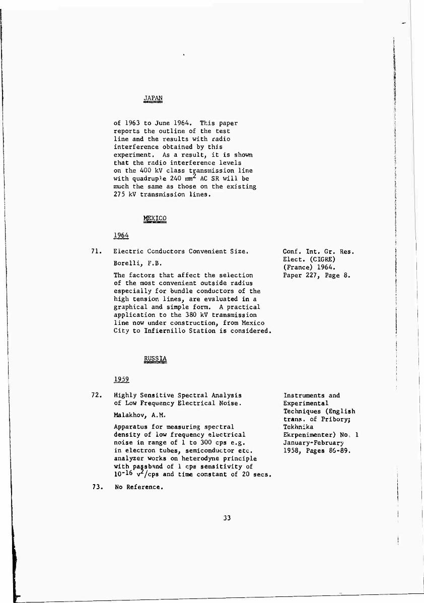
JAPAN
of 1963 to June 1964, This paper reports the outline of the test line and the results with radio interference obtained by this experiment. As a result, it is shown that the radio interference levels on the 400 kV class transmission line with quadruple 240 mm2 AC SR will be much the same as those on the existing 275 kV transmission lines.
MEXICO
1964
71. Electric Conductors Convenient Size.
Borelli, F.B.
The factors that affect the selection of the most convenient outside radius especially for bundle conductors of the high tension lines, are evaluated in a graphical and simple form. A practical application to the 380 kV transmission line now under construction, from Mexico City to Infiernillo Station is considered.
Conf. Int. Gr. Res. Elect. (CIGRE) (France) 1964. Paper 227, Page 8.
RUSSIA
i959
72. Highly Sensitive Spectral Analysis of Low Frequency Electrical Noise,
Malakhov, A.M.
Apparatus for measuring spectral density of low frequency electrical noise in range of 1 to 300 cps e.g. in electron tubes, semiconductor etc. analyzer works on heterodyne principle with passbnnd of 1 cps sensitivity of 10-16 v^/cps and time constant of 20 sees,
73« No Reference.
Instruments and Experimental Techniques (English trans, of Pribory; Tekhnika Ekrpenimenter) No. 1 January-February 1958, Pages 86-89.
33

RUSSIA
74.
1960
Obrazovanie i struktura pometkh v. vozduhnykh elekbricheskikh setyakh 0.4-35 kV.
Smirnov, B.V.
Formation and structure of noise in overhead electric networks at 0.5-35 kV; principal ranges of noise in range 0.05 to 155 kc/s are showed to be generators and transformers with their non-linear vs characteristics and insulators^ which form partial discharge impulses, structure and magnitude of noise from these sources.
Elektrosryaz, Volume 14, July 1960, Pages 66-74 See also English translation in Telecommunication No. 7, 1960, Pages 813-25,
75. The Input Impedance of Broadcast-Band Noise Meters.
Furmanov, I. M.
Relations are derived from which the input impedance of a standard Soviet interference meter (0.15 to 25 Mc/s) is calculated.
This impedance is small enough to effect readings when used with a standard noise measuring network for connecting to the terminals of industrial noise sources. To overcome the difficulty, an input circuit for the noise meter is proposed which includes a matched attenuator and whose impedance does not vary more than 107, from 150XU
76. Investigation of Interference from Corona on Transmission Lines.
Kafleva, K. Ya.
The levels of radio and HF interference by corona on lines without grouped conductors are permissible unless gradients exceed 26 kv/cm pk.
Conductors of planned 330 kV lines should have 33 am as mlnluum diameter. If
Radiotekhnika, Volume 15, No. 6, Pages 70-3 (June 1960)
Elektr5chestvo (USSR) 1960, No. 12, Pages 27-33 (Dec).
34

RUSSIA
gradient exceeds 26 kv/cm on transition to 330 kV, communication channels must be fitted with powerful output amplifiers and radio receivers in the neighborhood operated without outdoor aerials. The Interference levels drops rapidly with frequency and distance from the line. In some areas, permissible gradients may be 28 kv/cm pk.
77. Analysis of Noise in a 0.4/6 kV Power Network.
Venchkovskii, L.B.
Results of the study of the noise in a 0.4/6 kV oilfield power network at 150 c/s to 100 kc/s are given. Experimental data is analyzed statistically and approximate formula for the functions of the pulse-noise magnitude distribution found. (English translation in Automat, remote control (USA).
77A, Corona Investigation on Extra-High Voltage Overhead Lines.
Burgsdorf, V.V.
The report presents an account of experimental investigations on corona-losses, undertaken on test and operating lines and a description of applied measuring circuits, and suggests generalized characteristics for corona loss measurements under different weather conditions. Besides, it shows characteristic values of 330-500 kV line losses and the results of radio- noise and interference with HF cocmnunication channel measurements.
Automat; Telemekh (USSR), Volume 21, No. 8, Pages 1181-7 August 1960. In Russian.
CIGRE, Paper 413, June 1960.
35
.

RUSSIA
1962
78. A Method for Computing the High- Frequency Parameters of Overhead Electric-Power Transmission Lines.
Orlov, V.N.
A method of calculating the high- frequency parameters of overhead electric-power transmission lines is examined. The basic portion of the discussion is concerned with allowance for ground losses, which have a substantial influence upon the value of line attenuation. It is proposed to use, for this purpose, charts and approximate expressions obtained by the authors for various Carson functions.
Telecommunication and Radio Engineer- ing, Part 1, No. 7, July 1962, Pages 60- 70 (English translation of Russian Elektrosvyoz and Radiotekhnika).
1963
79. Interference from Partial Discharges on the Insulators of 0.4-35 kV Electric Lines.
Sarapkin, V.V.
The mechanism of formation of a system of pulses from partial discharges on the insulators of a three-phase line is described. The structure of the Interference spectrum is considered to depend on the following: the number of pulses in a series, the variation of amplitude, and the duration and instant of appearance of the pulses. The results of experimental research on interference in electric lines are quoted. Methods of calculating, the interference in the development of apparatus intended for operation through the conductors of 0.4-33 kV lines are developed.
Elektrosvyaz (USSR) 1963, No. 4, In Russian English translation in Telecomm. Radio Eng. pt. (USA), 1963, No. 4, Pages 64-73 (April 1963).
36

RUSSIA
80, Tracing the Sources of Radio and Telegraphic Interference from 110 kV lines by means of a fault detector.
Karamzin, A.P.
Describes the manner in which an interference locator type lP~i2 and a fault detector type D8 were used to trace sources of interference arising from 110 kV, transmission lines in the Sverdlorsk power system. The guilty line was found by successively cutting out all the lines passing through the affected area. It proved to be a seven mile stretch of two- circuit line carried on metallic pylons. Four offending sections were localized in two areas by means of a fault detector, in one case by the interference locator; and the final case by visual observation at night. The fault detector enabled fault to be located to be within 3 to 4 pylons, it is smaller, cheaper and more convenient to use than the l.p.12 instrument, and gives readings easily identifiable above the background of corona. The sources proved to be an assortment of faulty insulators, and bad connections in the shield wires.
Elektricheskie Stantsic (USSR) 1963, No. 3, Pages 82-4 (March) In Russian.
81. Some Special Features of Corona on High Voltagi D.C. Transmission Lines.
Popkov, V.l.
With unipolar dc corona, both increase in the electrode spacing and the use of negative polarity on the conductor decrease corona current and power loss; with bipolar corona, the higher ion densities cause higher corona current and power loss. Since the losses from two unipolar conductors are lower from those of bipolar conductors, it is suggested that DC lines be built on the independent towers spaced widely apart. It is shown that the earthwire in a unipolar system increases the potential gradient at the line conductor, causing
CEGB Conf. on Gas Discharges and the Electricity Supply Industry, Leather- head, 1963, (See abstract 3511 of 1963) Pages 225-37.
37

RUSSIA
higher corona power loss. Under certain conditions, corona can occur on the earthwire, and the resulting bipolar corona causes still higher loss. There is no correlation between corona loss and the radio noise from conductors. Greater interference occurs when the conductor is positive, and, although in rain the noise commences at a lower voltage than in dry conditions, the noise with higher voltages is lower in rain. Surface coatings are only effective in reducing interference from conductors having negative polarity. Screening wires, which generate super corona, are effective in suppressing streamers with positive polarity, and this reduces the radio interference.
1964
82, The 750 kV Experimental-Commercial Transmissions Line Konakovo-Moscow,
Akopyan, A.A,
The growth of the electric power industry in USSR makes it necessary to further increase the voltage for AC transmission systems. By the end of the next five year plan (1966-1970) it is planned to erect several powerful 750 kV transmission systems. The experimental-commercial 750 kV transmission line Konakovo-Moscow is to be erected for gaining experience and conducting research on transmission systems in this class. The report discusses several operations connected with the 750 kV transmission line.
Conf. Int. Gr. Res. Elect, (CIGRE) (France) 1964 Paper 413, Page 16.
83. Mctodika raschcta radiopomekh of korony na provodakh linii elektroperedachi.
Perelman, L.S.
Methods of calculating radio interference crom corona of conductors of power transmission lines, analytical method is described, which
Elektrichestvo, No. 10, October 1964, Pages 57-62.
38

RUSSIA
is claimed to overcome shortcomings of method proposed by R.E. Adams, that does not account for fact that vertical component of electric field in relation to distance to ground decreases at slower rate than some component of quasi-static field; hence calculation of radio interference should take into account wave characteristics of field, calculation of corona interference from 500 to 750 kV lines.
83A. The Corona Effect and Selections of Symposium on Long- Conductors for 500 kV Power Transmission Distance electro- Lines, transmission, 1964,
Burgsdorf, V.V. ***** 106-117'
This paper discusses corona loss and radio interference (RI). It gives RI data including statistical data, obtained in several types of weather and for several conductor surface conditions. It is recommended that statistical methods be used to determine the RI level of a line. It is stated that with a three conductor bundle of 1.2 inch dia. conductors, the interference is below their design limit for practically all of the time. No correlation between their meters and CISPR or U.S. RI meters is given. It is stated that aging of lines reduces interference by 5 to 8 times from that obtained with new conductors. Instrumentation is referred to which records without paper chart every l/2 to 10 minutes and which includes means for simultaneous statistical processing.
SWEDEN
1959
84. Wave Propagation Along Three-Phase Ericsson Techniques Power Lines and Telephone Lines (Sweden) Volume 15, with Power Induction. No. 2, Pages 221-48,
1QSQ Pettersson, G.A.
39

SWEDEN
Expressions are derived for the currents and voltages in a three-phase power line without earth wires. It is shown that a line that is not balanced by using transpositions is characterized by five impedances and three wave propagation states. The effectively transposed line has two characteristic impedances and two^ wave propagation states. The formula presented has proved to be suitable for practical analysis, of the characteristics of three-phase lines. In addition, expressions are given for the influence of the three-phase line on a telephone line.
1960
84A. DC Insulators, A Comparison with AC. CIGRE Paper 403,
Witt, H. June 1960-
Various aspects of DC insulation as compared with AC have been studied theoretically and experimentally, with particular regard to the possibility of converting the vast experience gained from AC systems into use for DC systems.
As a result, an attempt has been made to give reasonably definite recommendations for the insulation of HV DC lines to be used in the ef.timation of transmission costs.
These recommendations are considerably, influenced by the favorable fact that DC systems can be so arranged and controlled that switching surges and other internal overvoltages are negligible.
1962
85. Radiostorningar from Stodisdatorer. Elteknlk, Volume 5,
' Page& 45-7. Radio interference from pin type
40
ji^mtimm********'

SWEDEN
type insulators, study on Swedish 30 kV lines using wood poles, interference level can be reduced considerably by using special types of insulators having semiconductor glaze, best results were obtained with clamp-top insulators.
1964
86. Corona Loss and Radio Interference Conf. Int. Gr. Res. Measurements at High Voltage AC on Elect. (CIGRE) Test Lines in Sweden, France 1964,
Knudsen, N. PaPer 4U' Pa8e 17-
On a test plant erected by the Swedish State Power Board in connection with the Chalmers University of Technology in Gothenburg comprehensive corona tests have been carried out during the last years« Beside the general intention to broaden the theoretical and practical knowledge about the corona phenomenon there has been a special purpose namely to compare the behavior of double and triple conductors of the types used in Sweden which contain cables with a diameter of 3.2 cm and a spacing of 43 cm. The results of the experiment indicate that by the use of triple conductors instead of double conductors the yearly losses, apart from ice losses, are reduced from about 1.4 kw/km to about 0.4 kw/km and the radio interference level is reduced by about G dB in fair weather and probably somewhat more in bad weather. Expressed in another way the triple conductors has given approximately the same losses and radio disturbances at 460 kV as the double conductor at 400 kV. Variations between 407. and 957, in the humidity in the air did not seem to affect the losses but a slight decrease in radio interference with increasing humidity was observed. Bad weather has given Increasing losses in the following order: fog, dry snow, rain, wet snow, hoar frost. A method for calculating fair weather losses is proposed and future work is outlined.
41
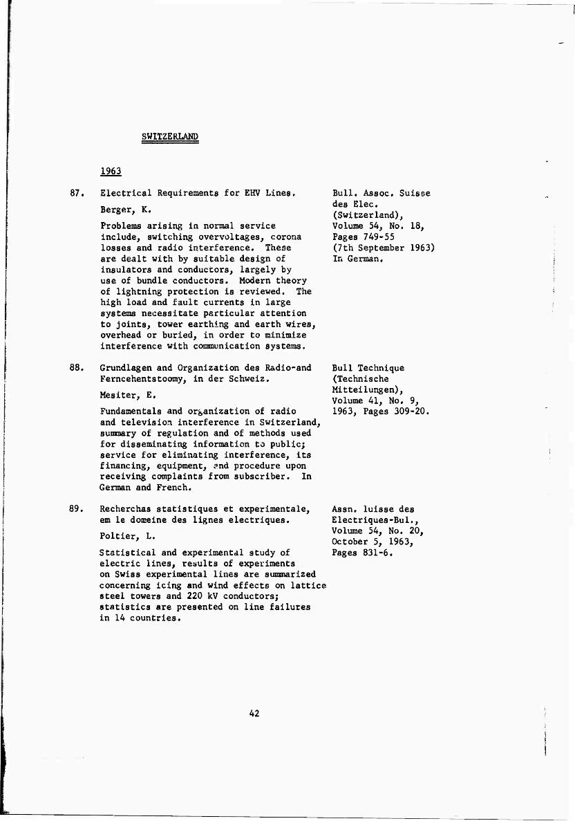
SWITZERLAND
1963
87. Electrical Requirements for EHV Lines.
Berger, K.
Problems arising in normal service include, switching overvoltages, corona losses and radio interference« These are dealt with by suitable design of insulators and conductors, largely by use of bundle conductors* Modern theory of lightning protection is reviewed. The high load and fault currents in large systems necessitate particular attention to joints, tower earthing and earth wires, overhead or buried, in order to minimize interference with communication systems.
Bull. Assoc. Suisse des Elec. (Switzerland), Volume 54, No. 18, Pages 749-55 (7th September 1963) In German.
88. Grundlagen and Organization des Radio-and Ferncehentstoomy, in der Schweiz.
Mesiter, E.
Fundamentals and organization of radio and television interference in Switzerland, summary of regulation and of methods used for disseminating information to public; service for eliminating interference, its financing, equipment, and procedure upon receiving complaints from subscriber. In German and French.
Bull Technique (Technische Mitteilungen), Volume 41, No. 9, 1963, Pages 309-20.
89. Recherchas statistiques et experimentale, em le domeine des lignes electriques.
Poltier, L.
Statistical and experimental study of electric lines, results of experiments on Swiss experimental lines are summarized concerning icing and wind effects on lattice steel towers and 220 kV conductors; statistics are presented on line failures in 14 countries.
Assn. luisse des Electriques-Bul., Volume 54, No. 20, October 5, 1963, Pages 831-6.
42

SWITZERLAND
90. Der Radiostoersuchwagen der Radio- and Femceh-Dienste.
Meister, E,
Mobile interference-locator for radio and TV services; details of electric equipment and its installation in Simca station wagon of 1000 kg load capacity; apparatus can cover range of 40 mc/s to about 1 GC; optical goniometer (Plirch of Viernheim, West Germany); directive, roof mounted, wideband dipole antenna, elect- rically rotatable at 0 to 120 rpm, and including telescope elements; panoramic circular oscilloscope, with its beam synchronized with antenna rotation, using 400 c/s generators; 220 V AC is converted from 24 V DC measurement supply, wobbulator- oscilloscope set scans 1-, 7-, or 9 Mc/s bandwidth as panorama.
(Technioche Mitteilungen PTT), Volume 41, No. 5, 1963, Pages 184-96.
43

AIR FORCE CONTRACT 30-602-3822
APPENDIX VII PART (2)
DI ) INTERFERENCE - HIGH VOLTAGE POWER LINES
AMERICAN LITERATURE 1960 TO 1966
The literature is in abstract form and arranged alphabetically by means of the authors name.
Pages 45 and 46 have an author index arranged alphabetically and on pages 47, 48 and 49 there is a subject index.
NOVEMBER 1966
44

RADIO INTERFERENCE-HIGH VOLTAGE POWER LINES
AMERICAN LITERATURE 1960 TO 1966
AUTHOR INDEX
AUTHOR REF.NO. AUTHOR REF.NO. AUTHOR REF.NO.
AIEE Working Gp.
1 Gabriellea,A. 15 Mather,R.J. 28, 29
Abboushi^A.K, 2 Graham, R.E. 16
Adams, G.E. 3
Griscom,S.B. 17
Maxwell.E.L. 30
Arlsmunandar,A. 4 Maziotti,!. 31
Armstrong, H.R. 4A Harmon,R.W, 18
Ball, CO. 5 Morris,R.M, 32
Bailey^ B.M* 5A Helstrom,C.W. 19
Barthold, L.O. 6 Hog1und,N.A, 19A Nigol,0. 33, 34
Hylten- Cavallius,N.
20 NEMA 34A
Bond, C.R. 7 Newell, H.H. 34B
Bouiet, L. 8,8A IEEE 21 Pakala,W.E.
(1966]
35, 35A, 35B, 35C
Clark, D.B. 9,10, 10A
Hinchnum Corp.
22 Pearson,G.A. 36
Denholm, A.G. 11,12 Jacobs, E.
Jordan, E.C.
23
23A
Perz, M.C. 37
Deitz, J. 12A La Forrest,J.J. 24, Rakoshdas, B. 38
DDC 13 25, 25A
Rawls, J.A. 38A
Egll, J.J.
Epstein, M.
13A (1957)
14
Leslie, J.R.
Lorch, J.
2u
27
Reichroan, J.
Robertson, L.M.
39, 40,
41, 42
43, 44,45, 46,47
45
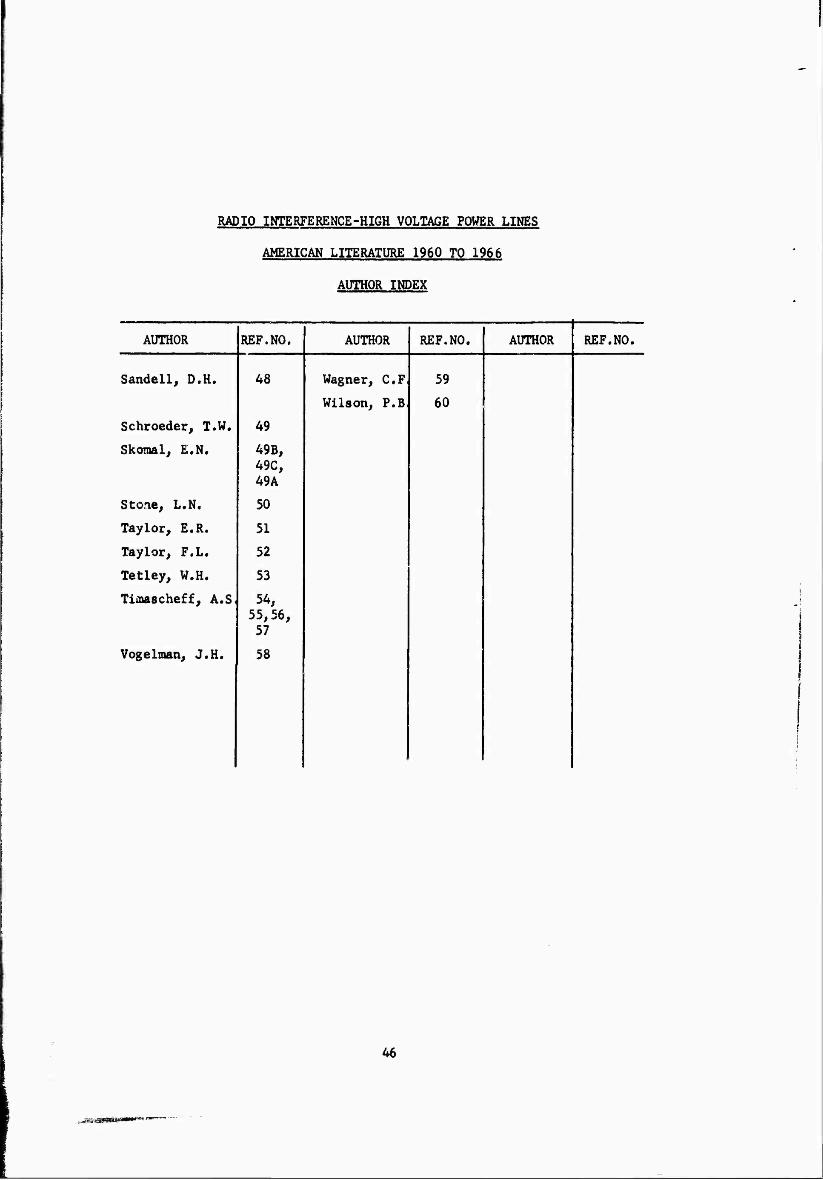
RADIO INTERFERENCE-HIGH VOLTAGE POWER LINES
AMERICAN LITERATURE 1960 TO 1966
AUTHOR INDEX
AUTHOR REF.NO. AUTHOR REF.NO. AUTHOR REF.NO.
Sandell, D.H. 48 Wagner, C.F
Wilson, P.B
59
60
Schroeder, T.W. 49
Skomal, E.N. 49B, 49C,
; 49A
Sto.ie, L.N. 50
Taylor, E.R. 51
Taylor, F.L. 52
Tetley, W.H. 53
Tioascheff, A.S 54, 55,56, 57
Vogelman, J.H. 58
46
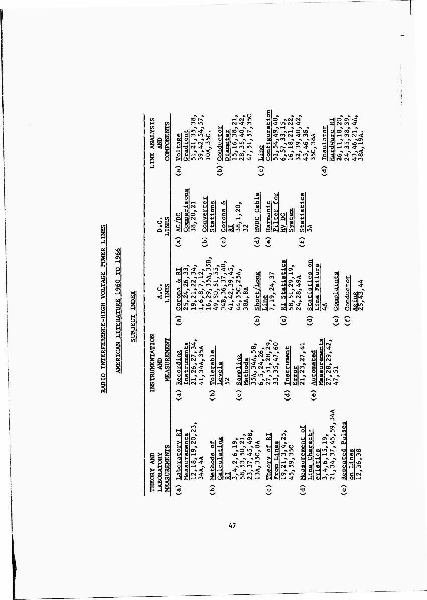
«3
<3
ti <u C w 0) t« »H 4J -o rH « o M > Ü
00 f^ CO IT»
•S »k m ^t •
X r-l C«! CO CM -* •<
•* «^ < r-« ON O m co fH
k 0 u 4J 0) o 4J 3 fl)
•o g c (0 0 •H u Q
rH CM US CM ^ fO
oo o i^ co sf m
<N «V % SO m fH rH CO U^
•^ •* •> m oo r^ rH CM »*
o •H u
00 «sCM CM ^ m CM "*
AiH •, •» »y
sr CO'CNJ ^ <o <3 •»co «^ •» «»oo
^ «s00 ON vp CO m r«. iH co -^ %
•H %vO CM CO iO «O VO »H CO Sf co
Hl 04
u o 0)
■U b OJ «fl
rH ? 3 -d n u
M s
•k *, m*
O ON -< CM CO «sf
•^ •* »k 00 00 <H • rH CO CM -<
•* •* «»ION rH m vOrH H co >5 ^
•^ •» •>< vO *^ CO 00 CM M Sf CO
CO
§ u 09 rH 0) 0) 4 •H CM 4J c: U t l-i 0 cd CÖ o « •H fi
CM > 4J o 3 * c «0 ki > oo o 4J 0
Ü <o ü OT ü
o CM
M|0O CM 0tf|c0 CO
V M aal rH 0 0 Xi o ^H •H m •H 4J u c U a n
2 0) c; <u •H o l ■U
r-l Q u
0} 4J
1 5 g > V)
■u in
*4
m * M co»* «icoio^m •. Oö co co CM ^m ^>t <
•* <MH < ^r«. ^m 4 so CM -»m r-l CO ON CM
CM CM r>. co m ^co •»
S * * * «t «svO •>■ O <I «^fHOOONOCOCMuSoO
o XM CM <\CM u1» «»^T CO • u •» <KNO ^ ikfQ ^ «s^C
IT» ON «»SO ON •* rH >!• CO CMr-lr-4^ISt<r, Sr^TCO
o o
ON rH
ON ON CM <r
rH 00 tn CM
•s •» oo ^• m CM
§ 0) ki
« 3 «0 o rH w M
•H *H c O u cd •H *.' co fe OS Ü
•H ,H 3 U 4) 1 •d cd C 3 c u •H <: 3 o M ^ sf U u
01 U-l
T5
o U
co <: IN» co CM •.
•^ CM CO
CM Nt
0) ^-1 a « « CO •H
* kl r-l rH « 4) Q J2
rH > 1 4J
Ö 5 CM 3 »n w Ü
ON O 00 -sCM sO 4J iTt yO J^ S C
•»CM oo r*. < ^CMSf «T ST «s «k CO CM rH m M
-> ^in co *i < in ^ -v « m »»fN. co c CO vO CM CO M
CM
CNI
00 r-4 CM m
CM ^J
co
M «9 u
t C o E u « « M u 3 o «9
JS <tf 3 £
CO CM
•k
o CM
M Ov iH
00 st rH »k
CM ^r co
IM o
•8 I
■kM •^^ o^
Ov CM •* < rH «s ^GO
»so »n «k vo »n ^ o
•s •» ««.«n CM co Cs, co
^tn co ^ .sr ^ ^<
Ml «kOO CO CO 0J|C0 tn CM rH
M ai
(0 IM 0) o c
•H > J u 0
H s
m CM
CO CO
rH ON CM m ON m rH SJ-
l« 9 i
u u u C AS
4)
kl
5 kt O 3 0» 4) « d
£ >H
•» "Of ON 4) m »
^ ^ rH ON m 3 M >* O. ^ »k
m CN •o r-l CO 4) ^ «k U
sO <t 3 -*«o ^ ^ O
«KrH 41 CO CM ^
«oo 4) C
;0
CM
•Ö
47

^3
§ •H ■U id c •H
1 g
in
<r st CM CO
CM 3
O n CM ^•
CM in
vo m CM ^
st -^ CM ^ ^
r-« ^ 00 CM •» «v •vtn <;
\o m «r
^CM m oo co m
0)
03 ro
m cn
m ON CM >t
c o
♦H 01 o u u o o
fO
m cn
> u
i r-< O
ON
CM CO
\0 ^t CM PO
3:|CM m
00
ol . ü . c B •o o 0)
g c »H J-l C0 CO 0)
•H •H M rH o > ^ 0 •H 4) (U D •o r-J ü 0 o s 4) c
e 09 CÖ <D . . M C U-l •ö U4
g 8 h4 o
a (9 O
V4 > Ü g •H P4 V4 AJ c ■ g 0) 0) •H (U c •i-l 0) O » rH u 0 •H 03
1 •H o •H 0) •H ■Ui <n •Ü PM -D <^ •p G 4»
S S M 5 0) Ü 3 5
4 V o AJ •o O a S Ö O l £ s s PM
0 C/J
•.^ ►J r^ O rH r-l 0)
cn « f-i »n 3
^co rH o «^ 0 r-4 O > 5 ON •» S •«
•»tn D CM m m •H in
•i «s -d ■« M CM rH S m OS CM c*> co
Ö0 rC ^ ^
•k Oll rH Ü ^ « K
g m -4' a rH g •H co ^ *J g m co > *< ti •i
« ON m «0 po 2 > <M ro £ •H
Ut •k «^ J »4 •k «H 3 oo rv U « fs. -U
C^t CM >t U CM «tf
M rH CM s «i a
CM »3 OtJ CM wt M U
m co
CM
u 0) > N u > C
r-l Q> «ö 3
5 O 0» M
rH Pu RJ ^ Jj *J Q Ü (J 0) o »H
CO o
o o calpo •H] ^ o st SB -H
3
CN ON
ON S
1 o o i 'J 1 | M c ^ c < O •H « •H öj
»4 o 3 •H ON U U AJ £ •H
M S <« *3 U (!) « « <J >
z 4J U •, Ü C 4) •H iJ «d 0) u u < o b£ > •o o
3 ä m 9) PO rH 1 3c s > co CM
00
48

• en
Q H
^'3
M 1 ftl 4ä w
U o r-4 c M-J c •H 4-1 o «1 > O 0 o ^ > <u <u d
■u •H •U c •d •o Ö fl) •H •P W 4J M Ü y •H 3 4J d o H T3 Ü U") d o O <u 0) 3 HJ 4J O 5 (Ö i-l Q, •H a ro •H •H <y TJ a ♦H •H <0 ■P •H
y M-l •\ JJ T» u C w tJ (Ü 4J u-t •v JJ q} 3 9 M-l >* •H 5 •H •r4 <u £ w r-l ^ IT» 3 4J U Ä W CM CO Q te OS (d < w <r « CO W
<-\ /-N ^k /-\ ^J r-H a ß s-/ ^> N-' s-/
49

uncorrected capactivie matrices. This paper derives correction factors for the latter matrices, thereby bridging the gap which has existed for some three decades since the last correction terms for inductances were introduced. Although the correction factors proved to be small for switching surge frequencies and some power line carrier frequencies and typical earth constants, they are not negligible for radio frequency applications.
5. Simulation Tests on Interference Rejection Antenna System
Ball, CO.
Method is described for receiving signal from known or selected direction while rejecting interference arriving from single direction, interference rejection is affected by using three identical antenna elements in conjuncticn with computer.
6. Radio Frequency Propagation and Attenuation on the American Electric Power Dequine-Olive 345 kV Line.
Barthold, L.O.
Attenuation constants for each of six characteristics modes of radio noise energy propagation alonj? double circuit vertical configuration line; comparison of calculated and measured electromagnetic field factors for each of these modes.
IRE Int. Convention Rec. Volume 8, Pt. 8 (Aeronautical and Navigational Electronics, etc.), 1960, Pa^es 3-9.
Paper 60-192, AIEE, Transactions on Power Apparatus and Systems, Part III, Volume 79, June 1960 Pages 303-309.
7. Experimental Compariions of Radio Influence Fields from Short and Long Transmission Lines.
Bonds, C.R.
Tests on section of 70-roiie-345 kV transmission line to show that for RI generation long line RI level can be obtained from short test line data; tests with single RI source on line are also described.
Paper 62-1406, AIEE, Transactions on Power Apparatus and Systems, Part III, Volume 82, April 1963, Pages 175-185.
51

;
8. AC Corona in Foul Weather I. Above Freezing Point.
Boulet, L.
After a brief survey of water appearance in the close-to-ground layer of the atmosphere, behavior of water drops in the electric field is analyzed and the mechanism of streamer formation shown. Water influence, causing corona increase, has two components: (1) discharges between conductor and passing drops and (2) streamers produced by water presence on the conductor. Results of some attempts to limit streamer formation when water is present on the conductor are reported.
9. Naval Civil Engineering Lab Port Heuneme California.
Clark, Don B., Hitchcock, Robert D.
Contiguous wrapping of transmission line conductors with High-mu tape for large radio-interference attenuation.
10. Evaluation of the Interference- Suppressing Power Conductor.
Clark, D. B., Brooks, J. L.
Field evaluation was made of a 4-mlle Installation of 13.2 kV, 3-phase, special interference attenuating power line, The special line with large magnitudes of Interference at its beginning, is shown to attenuate effectively over the broad frequency spectrum to bring the noise level of the line down to the level of the natural ambient In about half of its length. Impedance measurements of the power line as a transmission line showed It to be Independent of line terminations, and that considerable attenuation was present. Field intensity measurements showed that the intensity decreased rapidly in greater than Inverse square with distance, Indicating, a field propagated along the line, with no measurable
Paper 64-51, IEEE, Transactions on Power Apparatus and Systems. Volume 83, May 1964, Pages 508- 520.
AD-235 873 5/l 7/l March 60, NCEO TRO620TR0620 F006 09 201.
AD68 730 Div. 7/l 8/1 25/1 - Naval Civil Engineering Lab Port Heuneme California, December 61.
52

radiation away from the line. The effect of the high-permeability tape thickness on attenuation is considered theoretically and experimentally, and it shows that attenuation ia proportional to the tape thickness until the thickness is of the order of one skin depth. The potential applications and limitations of the new interference suppressing line are presented.
11. The Electric Stress Grading of Insulator Strings and Their Radio Influence Voltages,
Denholm, A.G.
Influence of such factors as diameter of tubing of which grading rings are made, distance between two rings, and their vertical position relative to insulator string on stress grading and RIV.
12. The Pulses and Radio Influence Voltage of Power Frequency Corona.
Denholm, A.S.
Initial results gained in detailed investigation of corona pulses which occur with alternating voltage on short lengths of conductor; examination of pulses which develop at different phases of applied voltage, determination of their true shapes, and measurement of corresponding radio interference voltage.
13. Defense Documentation Center Alexandria, Va. Electromagnetic Shielding, A DDC Report Bibliography«
14. Magnetic-FieId Pickup for Low-Frequency Radio Interference Measuring Sets.
Epstein, M.
Magnetic field pickup has been developed utilizing Hall effect In interroetallic semiconductors; unlike loop pickup, sensor responds to magnetic flux density and thus Is Independent of frequency; when used In conjunction with finite flux collectors; Its
Paper 60-90, ^iEE, Transactions oiv Power Apparatus and Systems, Part III, Volume 79, June 1960, Pages 167-174.
Paper 60-775, AIEE, Transactions on Power Apparatus and Systems, Part III, Volume 79, October 1960, Pages 698-707.
Bibliography for 1957-May 62, Page I, ARB10257.
Trans« on Electron Devices, Volume ED-8, No. I, January 1961, Pages 70-77.
53

sensitivity is 10 gauss in range of 30 cps to 15 kc/s; details of design and construction are given; device is extremely small in size.
15. Electrical Constants and Relative Capabilities of Bundled Conductor Transmission Lines.
Gabrielle^ A.F.
The author gives an excellent analysis of bundled conductor transmission lines in terms of their transmission capabilities versus single conductor lines. The results are tabulated in the form of useful tables and graphs. Inductive reactance^ capacitive reactance, surge impedance, bundled conductor or intra group spacing, number of conductors per phase and phase separation. The range of the analysis is such that it is applicable to voltage classes 69 kV to 700 kV. Detailed calculations for all data are given.
Paper 63-71, IEEE, Transactions on Power Apparatus and Systems, Volume 83, January 1964, Pages 78-92.
16. Radio Influence Testing of 70 Miles of 345 kV Horizontal Bundle Conductors.
Graham, R.E.
RI test results on 70 miles of 345 kV transmission lines are presented. The design of the 345 kV transmission line using 954 MCM (thousand circular mils) ACSR (aluminum cable steel reinforced) conductor bundled at 18 inch spacing, the use of standard suspension clamps, triangular space plates, and a horizontal phase spacing of 27 feet resulted in satisfactory RI level without control rings at the conductor hardware assemblies. Attenuation tests show that RI readings at one site are not materially affected by precipitation on a line a few miles away.
Paper 61-1027, AIEE, Transactions on Power Apparatus and Systems, Part III, Volume 80, February 1962, Pages 1022-1030.
54
17. De-Coupiing of Transmission Lines to Radio-Influence Voltage.
Griscom, S.B.
Field tests to determine whether several sections of transmission line could be satisfactorily de-coupled or isolated co radio interference using RC decoupler network with resistance shunted, for 60 cps purposes by relatively, high inductance; use of properly designed radio interference filters or decouplers is shown to provide high degree of radio interference isolation between sections«
18. Effect of Bundle-Conductors Field Influence on EHV Transmission-Line Design.
Harmon, R.W.
Description of some control shield designs used commercially at 343 and 460 kV; results of laboratory tests indicating- trend of art for multiconductor performance i ri reduced capital costs are shown possible for Cowers designed for new suspension hardware developed for multi-conductor bundles.
19. The Spectrum of Corona Noise Near a Power Transmission Line.
Heistrom, Carl, W.
A simple statistical model is proposed for the random currents and voltages induced in a high-tension line by corona discharges. The spectral densities of the voltage and current in the line are calculated from the model, with reflections from the ends of the line taken Into account.
The results can be used to estimate the radio Influence of a long power line on the basis of measurements made near a ahort test line.
Paper 60-1026, AIEE, Transactions on Power Apparatus and Systems. Part III, Volume 79, February 1961, Pages 1066- 1073.
Paper 61-171, AIEE, Transactions on Power Apparatus and Systems, Part III, Volume 80, June 1961, Pages 316-326.
Paper 61-795, AIEE, Transactions, Volume 80, Part III, December 1961, Pages 831-837.
55

20.
21.
Insulation Requirements; Corona Losses and Corona Radio Interference for High Voltage DC Lines.
Hylten-Cavallius N.
Insulation tests carried out up to 250 kV, and measurements of corona losses and radio interference made up to 230 to 450 kV are discussed by authors associated with ASEA High Voltage Laboratory Ludvika Sweden; it is indicated that corona losses of higher voltages will be less in dc than in ac system, as in case at lower voltages; radio interference from bipolar line is same or less than from correspondence ac line with same voltage to earth, dc insulates become more polluted than ac insulators.
IEEE Radio Noise Subcomaittee of the IEEE Transmission and Distribution Committee.
Paper 63-998, IEEE, Transactions on Power Apparatus and Systems, Volume 83, May 1964, Pages 500- 508.
An economic overhead electric power transmission system which produces no radio Influence is beyond the present state of the art. However sound engineering and attention to relevant aspects of design can produce a system having an acceptable (or tolerable) influence level. Such criteria as have been proved by research or experience together with accepted practices In Instrumentation and measurement of radio Influence fields are presented as an aid in planning extra-high voltage lines. Because of many variables and parameters that Influence radio noise from power lines, and because the level of a line varies with location am? time. It Is not presently possible to submit specific design u'lterla. Revisions In thinking In sane aspects of the problem may be anticipated as operating experience Is gained at the new extra-high-voltage levels.
This paper Is generally s good summary of the knowledge and experience gained over the past years In the RI field.
Transmission System Radio Influence, Paper 31, TP65-65 1965.
36

22. Description of the Procedures and Equipment for the Suppression and Mitigation of Electromagnetic Interference Voltage to Acceptable Levels«
Hinchman Corp. Detroit, Michigan, January 38, Page 76.
A description is presented of the procedures and equipment for the suppression and mitigation of electromagnetic interference voltage to acceptable levels« The report includes recommendations on power line components, such as, transmission lines and substation equipment for new and existing transmission lines« Transmission lines up to aad including 69 kV are reviewed« All available published studies by others as well as the knowledge gained from phases I, II and III, of the subject contract, were utilized in performing this study« A review of electric power utilities design, construction and maintenance procedures was also made and utilized in determining the recomnendations of this report« The procedures and equipment were determined from the above study and review for the suppression and mitigation of electromagnetic interference from overhead transmission lines« The conclusions of this report indicate, that these methods and procedures to limit the interference from overhead lines to the acceptable level established in Phase III of this contract, are desirable, feasible, and economically justifiable.
23« Predicting Antennas Role in RFI.
Jacobs, E.
Through good antenna design RF interference problems can be drastically reduced; however, even in antennas of exact sane type RF interference levels will vary due to minor differences in tolerance during manufacture; equations are given to predict interference from antennae as well as to facilltlate calculations of other antenna parameters.
Electronic Industries Voiun** 19, No. 5, my 1960, Pages 96- 102.
57

24« Radio Noise and Corona Loss Results from Project EHV.
LaForrest, J.J.
Fair and foul weather corona loss and radio noise data from the project EHV line are presented. Insulator loss and the dependence of corona loss on load current are discussed. Corona and radio noise data were logged continuously from three configurations tested at 500 kV and another at 700 kV and analyzed with a computer. They provide a basis for predicting line performance. The radio noise measurements from the test line are correlated with long«line performance.
25. Radio Noise Aging Characteristics of Small Aluminum Conductors.
LaForrest, JtJ.
Series of tests on aluminum conductors with smooth, clean, greased, and scratched surfaces to determine their radio noise aging characteristics; energized conductors acquired black coating after week of operation, that stabilizes corona start voltage of new conductors with smooth surfaces; radio noise performance of aged, scratched conductors approaches performance of aged smooth conductors after period of 104 days in energized state.
26. Radio Noise Studies on Power Lines with the Coronaphone.
Leslie, J.R.
Development of coronaphone is reviewed to show that correlation between acoustic noise and radio influence voltage exists; its application to study of power line corona sources on hv lines is discussed; on operating lines up to 230 kV, conductor corona was not found to be major contributor to radio noise field, either in day or wet weather* hardware noise is believed to predominate.
Paper 63-94, AIEE, Transactions on Power Apparatus and Systems, Part III, Volume 82, October 1963, Pages 735-750.
Paper 62-251, AIEE, Transactions on Power Apparatus and Systems, Part III, Volume 81, October 1962, Pages 424-428.
Paper 64-52, IEEE, Transactions on Power Apparatus and Systems, Volume 83, May 1964, Pages 495- 500.
58
27. Instrumentation for Radio Interference Measurements•
Lorch, J.
State of the art in development of RI measuring instruments: three types of noise and field measuring instruments utilizing pulse generators for calibration; power density meter, primarily intended to detect personnel hazard in immediate vicinity of high power radar and communication transmitters; requirements posed to RI measuring instruments.
28. Radio Interference from High Voltage Linos«
Mather, R.J.
Continuously recorded radio noise data collected from operating lines over a 3 year period are subjected to statistical techniques; some anticipated relationships were established; others failed to be verified; results* presented are based on records obtained at 2 hv, levels and with 3 different single conductor diameters.
J9« Radio Interference from High Voltage Lines•
Mather, R.J.
Study to conclude that radio interference from hv lines appears to follow normal distribution, only reliable conparison of level of 2 or more lines being comparison of mean and standard deviation of levels for at least a year, continuous recording appears to be most practical means of acquiring necessary data, random sampling over period to be studied is reliable method of inferring total characteristics.
30. Natural Noise Fields from 1 cps to 100 kc/s.
Maxwell, E.L.
Inst« Environment a?. Sciences-Proc« of Instrumentation for Environment. New York, Metropolitan Chapter, December 10-11, 1959, Page 12
Part II - Distribution and Correlation Paper 63-92, AIEE, Transactions on Power Apparatus and Systems, Part III, Volume 82, October 1963, Pages 775-782.
Paper 61-729, AIEE, Transactions on Power Apparatus and Systems, Part III, Volume 80, December 1961, Pages 890-896.
IEEE Trans, on Arüonnas and Propagation, Volv AP-ll, No. 3, May 1963, Pages 339-43.
59
Vertical electric and horizontal magnetic RMS noise field intensities were measured over frequency of 30 cps to 50 kc/s for all seasons of the year and for all time blocks; this data is combined with that of other workers in field to present natural noise density spectra from 1 cps to 100 kcps for central United States regions; seasonal and diurnal variations at these locations are seen to become small below 1 kc/s 10 ref.
31. Designing RFI-Free Communication Systems.
Mazziotti, I.
RFI susceptibility reduction program is outlined; prediction of various types of interference, design of equipment to achieve minimum of predicted interference, and measurements to determine how well th;.j goal is achieved are discussed.
32. An Investigation of Corona Loss and Radio Interference from Transmission Line Conductors at High Direct Voltage.
Morris, R.M.
The author discusses corona loss and RI generation on one single Drake conductor and on Drake 2-conductor bundle Installed on two short (370 ft.) test lines energized up to 600 kv positive and negative. Tests were conducted, under all weather conditions and RI measured up to 10 Mc/s. Corona loss for the two conductor bundle was 0.6 yo 0.7 that of the single conductor at the same voltage under all weather conditions« Dry weather, same gradients, showed the bundle had 3.3 times the loss of the single conductor. Negative losses appeared greater than the positive losses, all weather. At positive polarity, the bundle had 1/4 the 1 MC quasi-peak reading of the single at the same voltage.
Electronic Industries, Volume 20, No. 5, May 1961, Pages 114-118.
Paper 63-84, IEEE, Transactions on Power Apparatus and Systems, Volume 83, January 1964, Pages 5-16.
60
irUC^P*^*"

33. Corona Loss Research at Ontario Coldwater Project.
Nigol, 0,
Description of facilities and program, report to date in corona loss investigations on 4 conductor bundles.
34. Analysis of Radio Noise from High Voltage Lines.
I. Meter response to Corona Pulses II. Propagation Theory
Characteristics of corona discharges and radio noise meters are described and general approach for radio noise analysis on hv lines established; validity of approach is demonstrated by tests, also used to evaluate and to calibrate radio noise meters in terms of signal to noise ratio and quality of radio reception; theoretical method is presented for determining radio noise levels near hv lines; method is based on corona discharge and measuring instrument characteristics which determine readings of radio noise meters.
34A. NEMA Standards Publication, "Methods of Measurements of Radio Influence Voltage (RIV) of High-Voltage Apparatus, "Publication No. 107-1964.
34B. RI Caused by Particles on or Near EHV Conductors I - Fair Weather.
Newell, H.H.
This study was made to identify, photograph, and establish the radio noise importance of the fair-weather coronas occurring on an ac high voltage transmission line conductor. Excursions of fair weather interference to over 10 times the oase value of the line noise are attributed to corona plumes from vegetable particles and insects attached to the conductors. Vegetable particles and insects are dielectrics. Their plumes occur on the positive half-cycle
Paper 61-119, AIEE, Transactions on Power Apparatus and Systems, Part III, Volume 80, January 1961, Pages 304-313.
63-1023, 63-1022, IEEE, Transactions on Power Apparatus and Systems, Volume 83, May 1964, Pages 524-541, 554-558.
Paper submitted to IEEE 1965. No. 31, CP 65-133, IEEE Winter Power Meeting, New York February 1963.
61
of potential. Radio noise from the plumes overrides other corona noises associated with the dielectric particles, overrides the noise from weathered metal protrusions on the conductor strands, and overrides the normal noise from insulators, accessories and hardware« The conductor surface gradient, the total conductor surface area and the rate of gradient decay outward from the surface are important to both particle attachment and severity of plume formation.
35. A Practical Handbook for Location and Prevention of Radio Interference From Overhead Power Lines.
Pakala, W.E., Westinghouse R&D Center
Contents (Handbook for Location, Reduction and Prevention o: Radio Interference from Overhead Power Lines): Description of inter? 2rence and discussion of important characteristics« Sources of interference on lines: conductors; insulators; hardware; switchgear and other line apparatus; utilization equipment; and foreign lines and equipment« Location of power line and utilization equipment radio interference sources: Radio receivers for location of interference sources, antennas, procedures in location of power line source and other means of source location« Maintenance of radio interference control. Field surveys« Test method specifications and limits for overhead power lines.
35A. "Conducted Electromagnetic Interference Measurement Survey 500-130,000 Volts," Contract NBY-17825, December 1961, U«S« Navy Bureau of Yards and Docks« (Discusses and gives calibrations and test results of capacitor type voltage probes and ferrite core claap-on current probes for the measurement of radio Interference from high voltage lines. Tests made to prove feasibility
October 64, 64-9E4-565-R1
W. E« Pakala, Westinghouse R&D Center«
62
of measuring interference currents on all high voltage overhead lines with low voltage current probe and radio noise meter in bucket of lift truck with insulated boom. Ferrite current probe designed and built can be used with radio noise meter at ground potential on lines up to 15 kV to ground.)
35B. High Voltige Surge Measurements on Stranded Copper Conductor and on Magnetic Tape Wrapped Stranded Copper Conductor.
Pakala, W. E.
It has been found that SiFe magnetic tape contiguously wrapped around a copper conductor increases, to a marked extent, the attenuation of radio frequencies and radio interference pulses travelling along power lines. The purpose of the surge tests reported here was to find out if a magnetic tape wrapped conductor would attenuate high voltage surges, such as produced by lightning. The magnetic tape wrapped conductor was also tested for radio interference (RI) due to corona at 60 cycle voltages up to 150 kV. The frequency spectrum produced of corona generation was obtained and the electric field attenuation laterally from the line measured.
Contract NBY-32226. Dept. of the Navy. Naval Civil Engineering Lab. Port Hueneme, Calif- ornia. August 8, 1963. Wastinghouse Research Report 63-928-565-R1.
36. The Effect of Negative Corona Upon the Formation of Positive Corona.
Pearson, G.A.
It is shown that when alternating voltage is applied to large electrode configuration, presence of negative Trlchel pulse corona creates negative space charge which enhances formation of positive pulses corona.
Paper 61-942, AIEE, Transactions on Power Apparatus and Systems. Part III, Volume 80, 1961, Pages 847-850.
63

37.
38.
39.
Method of Evaluating Corona Noise Generation from Measurements on Short Test Lines.
Perz, M.C.
Background and underlying assumptions of modern analyses applied to corona noise are reviewed; methods proposed to compute noise current generated per unit length of conductor from quasi-peak value of field intensity, measured under phase conductors in center of open ended test line; in this method, measurements are taken at frequencies corresponding to minima of standing vaves, minima being insignificantly affected by line attenuation.
Pulses and Radio-Influence Voltage of Direct Corona.
Rakoshdas, B.
Behavior of range of conductor sizes, both smooth and stranded, is examined, at both positive and negative polarity, for better understanding of factors contributing to dc and ac radio interference, characteristits examined included shape of corona pulse, amplitude and charge context of pulse, repetition rate, RIV caused by pulses at 1 Nc/s and frequency spectra of RIV.
Paper 62-1405, AIEE, Transactions on Power Apparatus and Systems. Part III, Volume 82, December 1963, Pages 833-844.
Paper 63-999, IEEE, Transactions on Power Apparatus and Systems, Volume 83, May 1964, Pages 483- 491.
Radio Interference Studies for Extra-High-Voltage Lines In Ontario.
Reichman, J.
The authors cover the aspects of constructing an EHV test project for the purpose of studying the RI generation at Coldwater, Ontario on the Hydro-Electric Power Coomlsslon of Ontario facilities. Their contention Is that a number of prior attempts were made to correlate RI to conductor gradient* Their findings at that time showed that the literature and their tests were difficult to correlate« It was concluded that gradients as high as 18.8 kv/rms cm or •lightly higher were entirely practical and
Paper 60-95, AIEE, Transactions on Power Apparatus and Systems, Volume 79, June 1960, Pages 153-160.
64

40. Radio Influence Studies on Extra-High- Voltage Lines
Reichman, J.
progress report on studies and tests by Hydro-Electric Power Commission of Ontario on two test lines «t Goldwater^ Ontario; lines are capable of operation up to 600 kv and are each approximately 2500 ft. in length; they use four con- ductor bundle construction with 1.1 and 0.8 in. diameter conductors respectively.
41. A Sumnary of Radio Interference Studies Applied to EHV Lines
Rcichman, J.
Source and nature of corona discharges on EHV lines, and effect on RI meters is reviewed; relationship between con- ductor diameter and operating gradient it given; propagation experiments and node analysis of radio noise on Coldwater test line, using artificial sources# are described, results of long time RI recordings on 500 kV test line and close to 230 kV circuit are compared.
Paper 61-161, AIEE Transactions on Power Apparatus and Systems, Vol. 80, June 1961, pp. 261-270.
Paper 63-1024, IEEE Transactions on Power Apparatus and Systems, Vol. 83, March 1964, pp. 223-228.
42. A Summary of Radio Interference studies Applied to EHV Lines
Reichaan, J.
The authors summarize the efforts of approximately five years investigation of RI Studies on the Hydro-Electric Power Commissions test lines at Coldwater, Ontario. Tests Involve single and bundled conductors of varying slse operating at various voltages between 300 to 600 kV. They conclude small diameter conductors in bundles have the advantage from the RI viewpoint over larger conductors for the same gradient. Hardware contrlbutea more to RI than do conductors, (provided con- ductors are damage free and uncontamlnated) QP maters respond only to the largest corona sources. RI levels on EHV lines should be no greater than that from existing HV Unas In both fair and foul weather even at increased operating gradients.
Paper 63-1024, IEEE Transactions on Power Apparatus and Systems. Vol. 83, March 1964, pp. 223-228.
65
43. U«dvllle High Altitude Extra-High- Paper 61-236, AIEE Voltage Test Project - Part I - Report Transactions on Power on 4 Years of Testing. Apparatus and Systems,
Robertson, L. M. 1961^ pp< n5.725#
The transmission system in the west of the state of Colorado includes several lines crossing the continental divide at altitudes of up to 13,000 ft. Operating difficulties include severe weather con- ditions, high frequency of lightning strokes, high tower footing resistance and remoteness. The increase in system loading demands an increase in operating voltage and the Leadville project vas initiated to provide optimum design parameters for peculiar high-altitude conditions. The testing site at 10,500 ft. includes a variety of towers supporting a number of single and twc and four conductor bundle conductors to operate at either 230 kv or 345 kv. Results show that con- ditions as represented by radio influence and corona losses are not as severe as expected from extrapolation of data obtained from the Tidd or other low-altitude testing stations.
At Leadville blackening of the conductor and the usual Haging" effects were not observed. This precluded the segregation of altitudinal and conductor surface effects.
44. Leadville High-Altitude Extra-High- Paper 61-263, AIEl Voltage Test Project Part II - Corona Transactions on Power Loss Investigations Apparatus and Systi
Robertson, L. M. ^ m^ pp 725.n2#
Experimental results at over 10,000 ft. in exceptionally clean air conditions have shown single phase corona losses to be considerably less than those predicted from other investigations, or by the "Peek** or Peterson formula. In the absence of air-bourne pollution conductor-losses did not change with time and blackening of the conductor did not occur« Under these con- ditions the dependence of the losses on the air density factor (6) followed 5 or 5 1/2 rather than the more usual relationship of 8, Major increases in corona losses were only associated with falls of rain or snow.
66

45. Leadviile High-Altitude Extra High Paper 61-236, AIEE Voltage Test Project, Part III, Radio Transactions on Power Influence Investigations Apparatus and Systems,
Rob.rt.on, L. M. n*" ?«,' ^ ^ ™ 7 Dec, 1961, pp. 732, 743. If radio influence levels are plotted on the basis of dB above a reference of 1 [iv/m. an «linost straight line relationship is obtained. This relation- ship takes the form of dB » k (V-V ) + dBa.
Where k is a representative constant of the conductor; V is the voltage threshold for Increase in Roise level. The critical voltage decreases with altitude and depends upon d 1/2, where & is the air density factor. Comparison between Leadville results and those from low altitudes show that difference of altitude does not appreciably affect lateral attenuation.
46. Leadville High Altitude Extra-High- Paper 61-236, AIEE Voltage Test Project - Part IV - Transactions on Power Conductors, Towers, Insulators and Sub- Apparatus and Systems, stations Part III, Vol. 80,
Robertson, L. M. Dec. 1961, pp. 743-748.
Tests at 10,300 feet show that high altitude transmission lines to operate at 230 kV or 345 kV present few additional design diffi- culties over conventional lines. Single or bundle conductors may be used with conventional Joints, spacers, fittings and insulators.
It is possible to use wooden cross-arms with unearthed insulator strings should towers with improved lightning performance be required.
47. Leadville High Altitude Extra-High-Voltage Paper 62-1096, AIEE Test Project - Part IV - Conductor Tests Transactions on Power Robertson L M Apparatus and Systems, Robertson, L. M. ^ ^ Vol 8^
Corona loss and radio influence levels Feb. 1963, pp. 939-944. from 2 year testing on conductors, designed to bracket. 230 kV operating range at high altitudes, indicates that smaller conductors than originally estimated will perform adequately; results of HP tests gives values for radiation, and attenuation in 10«200 Me/s range; mechanical observations show conductor oscillations which are produced by heavy corona and damp cooductc' conditions.
67

48, Bibliography on Bundled Conductors
Sandell, D. H.
Paper 61-871, AIEE Transactions on Power Apparatus and Systems, Part III, Vol. 82, Dec. 1963, pp. 1115-1128.
49. 345 kV Wood Pole Test Line - Radio Influence and Leakage Current Investi- gation
Schroeder, T. W.
Tests are described performed on Illinois Power Co, one mile test line to ascertain whether wood pole H frame structure configurations, which had been successfully used for 138 kV lines, could be extra- polated to 345 kV lines; RI measurements were made with line energized both 3-phase and single phase, on which leakage currents and hot line maintenance techniques were studied; paper reports results and analysis of these aspects in detail.
Paper 63-1021, IEEE Transactions on Power Apparatus and Systems, Vol. 83, March 1964, pp. 228-236
50. Radio Interference Attenuation on Energized High-Voltage Transmission Lines, Measurement and Application
Stone, L. N.
Method of predicting additive effect of Individual radio interference sources; data on attenuation of RF energy from corona sources on energized HV lines. Paper 59-814.
The test circuit consisted of a single unit 350 kV test transformer, high voltage coupling capacitors and terminating network.
The recording Instrument was a Stoddart Radio Interference and Field Intensity Meter model NM20B.
AIEE - Trans. Vol. 78, Part III, (Power Apparatus and Systems) n. 45, Dec. 1959, p. 1238-45. Discussion p. 1245-7.
68

51. The Apple Grove 750 kV Project - 775 kV IEEE Transactions Radio Influence and Corona Loss Invest:!- Paper 31-TP-6J-151 gations
Taylor, E. R.
The Apple Grove Project has three test lines approximately 2400 ft. in length, each consisting of four conductor bundles. Different conductor diameters are used in each line; line A 1.382 in. diameter, B 1.192 in diameter C 1 in. diameter as these are considered to bracket the conductors that will be used for 200/750 kV transmission. Light load currents are simulated by circu- lating heating current. RI and corona loss data can be recorded automatically every 2 or 20 minutes on magnetic tape. Similarly with weather data. All three lines are compared under the same conditions. Initial data, 1.382 inch diameter conductor RI of 47.6 dB above 1 iiv/m at 100 ft. with a devia- tion of 6.7 dB; 1.10 inch diameter 50,6 dB; 1" 59 dB. Foul weather corona loss 27 to 365 kW/3 ph. mile. In foul weather corona loss and RI may be at times higher on the larger conductor than the smaller.
52. An Investigation of Radio Influence Paper 62-1367-AIKB Voltages on Transmission and Distribution Transactions on Power Lines on the Same Right of Way Apparatus and Systems,
Tavlor F L Pftrt II1' Vo1 8l' Taylor, F. L. fmh l96^ pp l062.io66
Field investigations of radio influence voltages on distribution circuits caused by parallel HV lines; attenuation factors for spacings between lines, between primary and secondary of distribution transformers, and attenuation along distribution laterals were determined for service conditions; noise reaching customer and acceptable signal to noise ratios are indicated.
53. Analytical prediction of Electromagnetic IRE Transaction on Environments Communications Systems
Tetlev V H y- CS"9 **> Jmm l961 Tetley, W. H. p 175ä85
Three approaches used by military agencies to predict statue of future electromagnetic environments are described; in all cases, basic technique of analytical prediction calls for solution of mathematical modele by digital computer.
69

54.
55.
57.
Bqulgradlent tin«« in the Vicinity of Bundle Conductors
Tiawcheff, A. S.
A method to determine the potential gradient values at any point in the vicinity of the subconductor grouping of a bundle conductor with any number of subconductors !<* presented. Charts are also given for which the (relative equigradient lines (field strength values) corresponding to the series of points of constant gradient values within the subconductor grouping for two, to six conductor bundles. The charts are arranged for both near vicinity and far vicinity.
Iffactive Dielectric Constant of the Atmosphere During a Saov Storm and its Influence Upon Corona Losses
Timascheff, A. S.
Tentative explanation is given of fact observed particularly in Canada! that emounts to heavy corona losses during snowstorms, sometimes exceeds those during rainstorms; explanation is based on con- sideration of "effective dielectric constant** during precipitation; calcula- tions and model measurements indicate large difference between rain and snow; surface potential gradient during heavy snowstorms may be increased by as much as 10Z to 201.
Paper 62-1369, AIBE Transactions on Power Apparatus and Systems# Part III, Vol. 82, April 1963, pt>. 104-110
Paper 64-39, IEEE Transactions on Power Apparatus and Systems Vol. 83, May 1964, pp. 492-495
Pield Patterns of Bundle Conductors and their Electrostatic Properties
Timascheff, A. S.
Method for calculation of field pattern of n-subconductot bundle, particularly when using medium sise digital computer; examples of patterns for 2, 3, 4, and 6 subconductors and for average values of subconductor distance to subconductor radius, derivation only from consideration of field patterns, of radius of single conductor with capacitance equivalent to bundle capacitance.
Paper 61-740, AIBE Transactions on Power Apparatus and Systems Part III, Vol. 80, pp. 590-597
70
58. Graphic«! Method Predicts Radio Influence Electronics V. 34, nS
Vogelman, J. H. 1"b-J' "" ,, 0 ' pp. 60, 62, 64, 66 Graphic-namml method of interference prediction it described which involves scries of sorting operations in which interference pairs (interference and interfered with) are gradually reduced in number until only significant ones reaain.
59. Traveling Waves on Power Transmission ISEE Transactions Lines with Special Emphasis on Radio Paper 63-1020 Noise
Wagner, C. F.
Traveling waves on polyphase transmission systems can be resolved into component waves in various manners. It is shown that for voltages below the corona threshold value, the resolution into a ground-current component and conductor components is susceptible to simple analysis because with this resolution one of the components, the ground component, has a high attenuation and distortion that is dependent almost entirely upon induced currents in the earth. Application of this type of resolution to the radio noise problem is discussed briefly.
60. Practical Approach to Interference Pre- Electronics V. 33 n37 diction and Suppression September 9, I960,
Wilson, P. >. ',^,• 84-87
Methods for estimating system interference problems and preventing them are presented; problem is examined by first considering circuit cards, then sub-assemblies, then combining of sub-assemblies into system package.
71

AIR FORCE COOTRACT A.F. 30-602>3822
APPENDIX VII PART (3>
RADIO INTERFERENCE - HIGE VOLTAGE POWER LINES
AMERICAN LITERATURE PRIOR TO I960
The literature is mainly in abstract form and arranged alphabetically by means of the authors1name or by institute, association etc. In a few cases additional references were numbered using letter A or B suffix.
Pages 73 to 88 contain abstracts. Pages 89 to 93 references mainly not abstracted.
72

1. Adams, G. E., "Radio Interference from High Voltage Transmission
Lines as influenced by Line Design" - AIEE Trans, pt. Ill, April
1958, pp. 54-63.
Results of calculation procedure as reported previously and are intended to show effect of principal items of line design upon interference level: vertical versus horizontal configuration, interphase spacing, center-to-center spacing between conductors of a bundle, and conductor phasing and circuit separation for double- circuit lines. Effect of attenuation of RI level as calculated. Single conductor, 3-phase, double circuit line. Discussion; Mention of Swedish method of calculation which compares well with Adams' but is simpler. Table of limit versus conductor size and phase spacing given.
2. Aggers, G. V. and Pakala, W. E., "Measuring Radio Interference
from High-Voltage Apparatus", Electric Journal, December 1933.
Describes test results with coupling capacitor used up to 60 kv to measure conducted voltage up to 0.60-1.5 Mc/s, Effect of changing resistance in series with coupling capac- itor from a few ohms to 1200 ohms. Description of choke coils used and their impedance curves.
3. Aggers, C. V. and stoddard, R. N., "Suppression of Radio Interference
using Tuned Choke Coils". Electric Journal, 1934, Vol. 31,
pp. 305-307, 367-370.
Discussion of design of choke colls for audio, carrier and radiobroadcast frequencies.
4. Aggers, C. V., and Pakala, W. E., and Stlckel, W. A., "Effect of
Radio Frequencies of a Power System on Radio-Receiving Systems".
AIEE Trans., Vol. 62, 1943.
Describes measurements on distribution lines and gives curves of coupling factor of AM broadcast antennas to power lines.
73

3. Atta, E. V., and White, E. L., "Radio Interference from Line
Insulators", Journal AIEEf September 1929, pp. 682-86.
General discussion of RI from high-voltage equip- ment , pin type insulators, suspension insulators. Gives attenuation curves perpendicular to and along 55 kv line for wet aid dry weather.
6. Brown, R. D., "Radio-Noise Source Aids in High Voltage Studies",
Electrical World, April 1, 1957, p. 72.
Description of suspension insulator with 0.1 inch spark gap connected across it for noise source. Holes in porcelain for mounting spark gap. Gap of brass machine screws filed to a point. Frequency spectrum of this source extends into TV bands.
7. Cheek, R. G., Moynihan, J. D., "A Study of Carrier Frequency-Noise
on Power Lines" - Part I Theoretical Considerations and Measuring
Techniques, Vol. 70, Pt. II, 1951, pp. 1127-34, AIEE.
Part II Results of Field Measurements, Vol, 70, Pt. II, 1951,
pp. 1325-34.
I. Characteristics of noise and response at receivers. Discussion of noise meters.
II. Results of series of measurements of conducted carrier frequency noise levels on lines from 23 to 230 kv. Used Conventional coupling capacitor in series with drain coil and Stoddart NMlOA meters. Variation of noise with frequency and weather.
8. CISPR (Canada) 302 5-10-594 Department of Transport, Ottawa, Canada.
Incidence and Nature of Power Line Interference
(Not for Reproduction)
Given number of sources, service interfered with, line voltages, types of sources and degree of interference in microvolts per meter. (Some of these sources such as non-current carrying parts caused interference to TV. There may be no cor- relation with TV frequency voltage on conductors to radiated interference on these types of sources.)
74

9. GISPR (Japan) 304 - Power Line Radio Interference
Describes radiated and conducted tests on distribution and high voltage circuits at 0.6 and 1.4 Mc/s and conducted tests at I Mc/s on insulators. Mean values and standard devia- tions are given of quasi-peak (1/600) for 0.6 and 1.4 Mc/s of nation-vide variation of the Maximum Noise intensity of Distribution Line RI.
10. CISPR (Sweden) 312 - Radiation from Power Lines
Discusses damping and spreading conditions^ dependence on frequency etc. Proposals are discussed concerning permissible interference limits &nd methods of measurement. Measuring frequencies of 0.16, .34 and 1 Mc/s are chosen.
U. CISPR (Suisse) 303 - 1938 Contribution to the Estimation of Radio
Interference from Power Lines by J. Meyer de Stadelhofen and W. Walter
(Bern).
The authors describe measurements with CISPR meter on power lines and laboratory measurements on power line com- ponents. Conducted measurements were made at 1 Mc/s using capacity coupling and 300 ohm loading. Radiation and attenuation measurements up to 6 Mc/s.
12. CISPR (Germany) 308 - Radiation from Power Lines. (Not for Reproduction)
Includes along with radiated measurement methods a conducted measurement circuit using coupling capacitor and 130 ohm load for line components. Measurements at 0.230 + .03 Mc/s 0.430 + .05 Mc/s are proposed.
13. CISPR (U.S.S.R.) 304 - 1958 Radio Interference From Lines
This report includes conducted test circuit similar to NEMA 600 ohm circuit. Radiation measuruiient data on 240 and 400 kv lines up to 150 Mc/s are given.
75

14. CISPR/B/WG3 (Munich) 1 - Measurement of Interference from Power
Lines
A tabulation is given of test frequencies and load resistance values etc. useO by several countries for conducted measurements of high voltago. apparatus. The highest test frequency is I Mc/s. It is proposed to use coupling capacitor method for frequencies below 30 Mc/s. For frequencies above 30 Mc/s it is stated that current measurements only are suitable.
15. CISPR ( Secretariat) 416, July 1939. (Not for reproduction)
The CISPR concluded that its discussion on the outcome of the meetings of the CISPR Sub-committee B Working Group on measurements of interference from power lines, held in Munich, June 1958, has confirmed that there is insufficient experience to enable a specification to be prepared for the measurement of voltage on high voltage lines and equipment at frequencies above 30 Mc/s. - Decides that the following question should be studied: What are the characteristics of a measuring system suitable for the measuring of the Interference voltage produced by high voltage lines and equipment at frequencies above 30 Mc/s?
16. Corbett, W., Radio Interference Problem, the Power Co. AIEB Journal,
October 1925, p. 1057.
General discussion and explanation for need for RI considerations. Classes and courses.
17. Fahre, M. J., "Experimental and Theoretical Study of the Mechanism
of Propagation and Radiation of Radio Noise Emitted by High Voltage
Lines11 Bulletin, Society Francaise des Electricians, Seine, France,
Vol. 3, #31, July 1953, pp. 419-24.
RI spectrum, attenuation, long and short lines. Theoretical analysis of impulse spectrum.
18. Flex, Edgar H., "The Radio Engineer's Responsibility in Coping with
Man-Made Interference". Proc. of IRE, Vol. 17, 1929, pp. 1385-89.
General discussion, no data.
76

19. Forrest, V. J. and Martin, R. E., "Appendix,Laboratory Methods for
Che Measurement of Radio Interference from High-Voltage Insulators
and Other Plant" part of "Progress Report of Study Committee on
Insulators (No. 5)" by G. H. Gillam CIGRE #215, 1958.
General discussion of measurement methods in measurement of interfering field (radiation), with NEMA test circuit (cap, in series with 600 a and RF choke in power supply), and measurement of RF current in earth circuit from bottom of insulator.
20. Foust, C. M. and Frick, C. W., "Measurements Pertaining to the
Coordination of Radio Reception with Power Apparatus and Systems",
AIEE Trans., June 1943, Vol. 62.
Compares radio noise meters and gives data on radio influence voltage from high voltage apparatus. Dis- cusses test voltages and limits when measured with the NEMA 107 conducted measurement circuit. Gives curves of under line antenna radio influence voltage ratios and discusses the relations of RIV of apparatus to radio-receiver noise.
21. Ghesquiere, J. D. and Bennett, S. A., 4th Conference on Radio
Interference Reduction 1958. - Measurements of Electromagnetic
Interference on High Voltage (50 kV) Transmission Lines«
This paper reports on a study of electromagnetic interference from high voltage transmission lines performed by the Hinchman Corporation under Bureau of Yards and Docks Contract.
Describes radiated and conducted measurements on lines in service. Radiated measurements were made from 30 cps to 1000 Mc/s. No measurable radiation o'wcained above 25 Me/a. Conducted measurements made with 66 kV porcelain encased 0.005 mfd capacitor mounted near conductor by suspension from cross-arm. A 600 ohm resistor with 50 ohm coax across 50 ohms to ground level and terminated there in 50 ohms. This conducted method proved satisfactory from 0.015 to 25 Mc/s. Calibrated in the laboratory with signal generator. Mo correction factors for coupling system given in this paper.
77

22. Gill, A. 0. and Whitehead, S., "Electrical Interference with Radio
Reception", Journal IEE, 1938, 83, p. 345.
Nature of interference: signal to noise ratio. Measurement of interference (radiated). Comparison of various methods. Sources of interference: trolley-buses; HV overhead transmission lines high frequency appara^js, electric elevators, telecommunication apparatus, domestic items. Methods of suppression at source and at receiver. Gives field strength beneath 132 kV line up to 20 Mc/s and attenuation out 0.6 miles and up to 18.5 Mc/s.
23. Jancke, G., Holmgren, B., Pettersson, G. A. and Akerland, P.,
"Protective Measures Against Telephone and Radio Interference
from High Tension Lines", CIGRE 338, 1954.
General discussion of RI phenomena. "As a general estimate for broadcast reception a signal to noise ratio of about 40 dB gives reception entirely free from inter- ference whilst i ratio of about 30 dB will give relatively satisfactory reception. For a signal field strength of 1000 iiv/m interference field at receiving aerial should amount to 10 tiv/m maximum for undisturbed reception and 30 tiv/m for fairly acceptable reception". Measurements made with a "frame aerial". Damping of field perpendicular to line: reduction at 50 m, 22 dB; at 100 m, 32 dB; at 200 m, 42 dB. For 220 kV and 380 kV lines gradient about 15 kv/cm rms but "conductor diameter should be selected where possible so that a lower field strength is obtained which may be estimated at 13 kv/cm". Measures for reducing effect of RI,
24. Jenssen, M., "On Radiation from Overhead Transmission Lines",
Proc. of IEE. Vol. 97, Part III, 1950, pp. 166-178.
The general problem of radiation from lines is discussed and the theoretical background is sketched. The radiation is calculated by the usual approximate method, i.e. the current distribution of the principal wave in an infinite line is first determined, and the radiation field of a finite line is then calculated on the assumption that the current distribution is the same. The method is applied to lines in free space, to single-wire lines above earth of finite conductivity (earth-return lines), and to multiple
78

lines above earth of finite conductivity. The current distribution and possible wave types in some typical multiple- lines are analyzed, it is shown that only the wave in the earth-return line, and the corresponding wave type in the multiple line, will produce appreciable radiation. Formulae for calculation of this radiation field are given, and experimental results are described. Conclusions are drawn regarding interference in carrier-line systems and the use of long-wire transmitting antennae.
25. Jespers, P., "Calculation of the Level of interference Carried
by a High Voltage Line in the Event of Faults Producing Flash-
overs in a Chain of Insulators" CIGRE #314, 1938.
Theoretical examination of build-up of spark impulses considering chain of insulators and faulty Joints as capacitors. By Laplace methods derives area under-pulse corresponding to its spectrum density. Checks results with lab tests.
26. Hinchman, "Report of a Review of Past and Current Work on Electro-
magnetic interference Voltage from Electric Power Transmission
Lines" - 23 November 1955, Hinchman Corp.
General summary of references indicating mechansim of corona and Rl. Effects of conductor diameter, spacing and height, ground wires, line termination and length, frequency, attenuation; line hardware and insulators, weather, choke colls. Gives standards and measurement methods including Joint Coordination Committee Standard (NEMA Clrcult-107) for conducted Riv measurements.
27. Hinchman Corp. "Report and Criteria of Method of Measurement and
Recommended Allowable Limits of Electromagnetic Interference
Voltages from High Voltage Transmission Lines" 25 October 1957.
Correlates information obtained during field studies of a number of 91.6 kv overhead lines of radiated (30 cycles to 1000 Mc/s) and conducted measurements (15 kc to 25 Mc/s), and "establishes levels of radiated and conducted
79

interference from acceptable economically - designed and maintained overhead transmission lines up to 66 kV". Used Stoddart URM-41, URM-6, PRM-1A, ÜRM-47, URM-17 receivers. "Above 25 Mc/s, there was no measurable interference", from well-maintained transmission lines". "It is concluded that high frequency interference is not inherent in veil designed and properly maintained transmission lines." Readings taken under line and at 25 and 50 ft. Used URM-6 and PRM-1 for conducted measurements, at I Mc/s coupled through coupling capacitor in series with 600 ohm variable resistor (NEMA circuit) paralleled by coil. Due to mismatch resorted to 0.005 mfd. in series with 550 in series with 50 ohm coax, but indicated as hazardous. For safety resorted to capacitor mounted on pole with coax, shunted with 50 ohms and safety cutout to ground. Calibration difficult above 4 Mc/s and becomes unreliable below 0.015 Mc/s.
Radiated tests on 41.6 kv lines of types of construction: flat with pin insulators, flat with post insulators and shield wire with post insulators. Nine test locations on lines of various age and load, wooden poles and cross-arms, length in excess of five miles, test spectrum from 30 cps to 15 kc wich loop and vertical rod under line at 25 and 50 feet and with horizontal dipole under line from 25 Mc/s to 1000 Mc/s.
Conducted tests at 6 locations simultaneous with radiated.
Gives »'Military Criteria" for radio interference measurements, methods and limits (14 kc to 1000 Mc/s) for overhead lines to 66 kv.
28. Dwitht, H. B., "Some Aspects of Surface Voltage Gradients on
Power Transmission Lines", AIEE Trans., Vol. 76, Part II,
December 1957, pp. 1217-1219.
Discussion of separate design for each phase to reduce gradient. Three-phases at same height gives gradient on center conductor, for grounded neutral, 7% higher than outer conductors. Gives formula for ratio of difference In rms values of charge of middle and outer conductors. Example given where radii of outer conductors Is decreased by 8.5X to make gradients of all conductors equal to that of middle conductor. "Calculations made for only one phase, as though the other phases were absent or at an Infinite distance, can be In error by a large percentage". Example
80

where calculations give result 21% too low. "Indoors, under a roof with metal beams the amount and distribution of charges may be strangly affected and measurements would be different from those on an outdoor line". With conductors per phase, one above the other: "difference between charges of two (sub-conductors) is — less than l?.11.
29. Hinchman Corp., "Description of the Procedures and Equipment
for the Suppression and Mitigation of Electromagnetic Interference
Voltage to Acceptable Levels", 26 January 1958.
States that "Limits of interference have been established at 15 microvolts pex* meter at 157,000 feet from the apparatus". Sources RI on sub-transmission lines (12 kV to 69 kV) are given as insulators, tie-wires, con- ductors, poles cross-arm hardware, guy wires, ground wires, power equipment and apparatus, corrosion and contamination. Gives percentage figures of RI sources from Canadian report. Recommended construction practices to reduce RI. Methods and hints for detection of RI sources. Recommended practices and specifications.
30. Cooke Engineering Company, "Electronic Interference Surveys of
Automatic Telephone Equipment", Final Report - Contract NBY-13014,
Bureau of Yards and Docks, 8 March 1958.
Aural monitoring of RI-FI meters, rf voltage and current measurements in frequency range from .014 to 1000 Mc/s using receivers AN/URM-6, AN/PRM-1, AN/URM-47, AN/URM-17 and Cooke Engrg. Co. calibrated test toroid for measuring noise currents. Radio Frequency interference voltage measurements of (1) conducted interference levels between pairs on telephone lines and (2) between one side of line and ground; noise currents on load sheaths: radiated rf levels. Radiated measurements inside exchanges with vertical rod in frequency range from 26 to 400 Mc/s or with horisontal half-wave dipole antenna.
81

31. Hinchraan Corp. "Report and Criteria of Method of Measurement and
Recommended Allowable Limits of Electromagnetic Interference
Voltages from High V Itage Transmission Lines of the 132 kv Class",
22 September 1958.
Similar in wording and content to report on 66 kv class and used same instruments. No measurable radiated interference in frequency range of 23 to 1000 Mc/s. Conclusion: A fairly accurate evaluation of conducted interference can be made from radiated interference measure* ments. The need for more accurate measurement of conducted interference does not appear to justify the large expendi- tures of time and money that would be required. Radiated interference from 120 kv 3-phase overhead lines at 12 locations in southeast Michigan. Types of construction: - steel tower, steel pole, wood H-frame; four conductor sizes - 3/0 copper, 266.8 MGM ACSR, 477 MGM ACSR and 795 MCM ACSR; in excess of 5 mile lengths from 30 cps to 1000 Mc/s. From 30 cps to 15 kc under line with loop and rod antenna 25 and 50 feet from line, 14 kc to 8 Mc/s horizontal with loop 25 and 50 t^et from line, 25 to 1000 Mc/s with dipole under line.
Includes "Military Criteria" for Rl measurement, methods and limits (14 kc to 1000 Mc/s) for overhead lines from 70 kv to 132 kv omitting conducted measurements.
32. Hinchraan Corp., "Desctiption of the Procedures and Equipment for
the Suppression and Mitigation of Electromagnetic Interference
Voltages from Transmission Lines of the 132 kv Class to Acceptable
Levels" 5 November 1958.
Similar to wording and content in report for 66 kv class. Includes recommended specifications similar to those recommended for 66 kv class.
33. Hoshiai, G. T., T. Yamada, Mita, N., Yoshion, S., "Radio Interference
Research in Japan with Special Reference to EHV Transmission Lines",
Paper No. 403, CIGRE, Paris, France 1956.
8?

M5P dB and 45 dB are representative values for RI for fair weather directly under the conductor for 410 mm and 520 mm ACSR respectively at 250 kv operating voltage". Used noise meters similar to Ferris - 32A. Gives RI (radiated) under line on Tanashi Test Line: 35*0 mm diam., 34,2 mm diam., 28.5 nm, 25.33 and 2 X 240 mm /40 cm (22.4 mm diam.) ACSR* Curve of effect of humidity increasing from low values at 50% to about twice at 867.. Effect of rain. Relation between single and 3-phase lines: "RI on 3-phase line is about 2 dB higher than that on single-phase line at same surface gradient". Give an empirical relation between RI and conductor surface gradient. Found little difference in RI from horizontal and vertical configurations even though surface gradient higher for vertical - attributed to unfavorable weather during measurement on horizontal.
34. Langdon, J. L. and Bradshaw, E., "Radio Interference from
Discharges on High-Voltage Line Insulators". Journal lEE^ 1934,
Vol. 75, p. 643-652.
Laboratory field investigations. Measured discharges through series air core transformer to thermionic voltmeter. Pin and suspension-type insulators. Effect of rain and humidity. Field meter consisted of vertical rod antenna to receiver from which voltmeter measured in wave lengths 300-500 and 1000-1800 meters.
35. Leslie, J. R. and Jones, 0. E., "Interference Studies on 250 kv
Wood-Pole Circuits - Use of over-sized Center Phase Conductor"
CIGRE 1958, No. 309.
Studies of Radio and TV Interference from 115 KV wood-pole line converted to 250 kv and from one mile test line using boundled conductors and small inter-phase spacing. Measurements with Ferris 32 B at 1 Mc/s showed converted line noise Increase of five times that of standard 230 kV line. Laboratory investigations of insulator noise shoved that their radio interference production was negligible. Measurements at 5D-250 kV at base of carrier coupling capacitor at end of line was 20 dB higher than normal. Used a meter with 5-element Yagl antenna on truck for TV interference tests. Also, VHP probe tuned to about 18 Mc/s fastened to Une-llne stick used to localize
83

Individual noise sources. TV interference decreased to negligible value during rain. Metal-to-metal sparking reduced by tightening hardware resulting in decrease of level by a factor of 10.
Test line: bundle conductor 477 MCM spaced 9 in. in vertical direction using conductors from converted line. Two ground wires. RF choke coils. Voltage 230-270 kV. Measurements under line and 50 feet away given in curve at 1 Mc/s for 230-270 kV.
Surface factor of 0.79 chosen by experience. Economics of oversized center phase conductor: reduction in spacing from 25 to 18 ft. by using 8% larger in diam. cond.
Use of 18 ft. phase spacing: 795 MCM for all 3 phases in unpopulated areas (corona voltage 237 kV) 1192.5 MCM (1.338 in. diam.) in densely populated areas and for center conductor for 7 miles either side (corona voltage 276 kV) and used 795-1192-795 MCM for phase con- ductors in sparsely populated areas (corona voltage 252 kV) and 2 dB attenuation per mile,
36. Leslie, J. R., and Woodington, ?. W., "Field Studies of Noise
at Television Frequencies from Power Circuits", AIEE Trans.
Part HI, August 1956, pp. 656-661.
For wood poles lines UHF noise is generally caused by noneurrent-carrying metal parts which have become loose. Insulators, including untreated type, usually quiet. Transmission circuits are generally quiet, except where suspension insulators are used as Jumper supports. Survey of 148 poles of 12 kV construction, loose ground wires and staples and loose Ctoss-arm braces and double arm spacer bolts responsible for significant UHF noise. Three loose insulator pins (steel), a split insulator and open fuse contact which was swinging in the wind. At 200 megacycles at 20 feet from pole measured 100 and 2000 micro- volts per meter when tapped gently with mallet. "Radio noise (1 Mc/s) under line was usually not increased by loose hardware, insulator noise predominating to give measured level of 16 tiv/m. Loose ground wires gave rise to 1 Mc/s as great as 4000 yv/m, one-half to a span away." Noise mechat. siu: - steel cross-arm braces as half wave dipole - quite »road-banded.
84

37. Lippert, Pakala, Bartlett, Fahrnkopf, "Radio Influence Tests
in Field and Laboratory - 300 kV Test Project of the AGE Co.1'
AIEE Trans. Vol. 70, Pt. X, 1951, pp. 251-69.
Gives RI data f *: test line on several conductors as a function of line voxtage up to 525 kV. Effects of weather on chart records. Effects of line termination, changing of line length and local source on conductor, and distance from line. Single phase to three phase comparison with peak, quasi-peak, and average detectors. Comparison of Stoddart and Ferris meters. Radiation tests from 0.015 to 120 Mc/s. Gives conductor diameter versus line voltage for 32 foot horizontal spacing. Laboratory tests on weathered and new conductors dry and with artificial rain using NEMA 107 measuring circuit. Signal to noise ratios for several qualities of reception using Stoddart and Ferris meters and corona type radio noise.
38. McMillan, F. 0., "Radio Interference from Insulator Corona",
AIEE Trans., V. 51, 1932, p. 385-91.
Loop tests in Laboratory.
39. McMillan, F. 0., "Some Characteristics of dc Conductor Corona",
AIEE Trans., Vol. 54, 1935, pp, 282-292.
Laboratory study of polarity characteristics of ac corona on polished, weathered, multilated and con- taminated conductors 0.999 to 0.422 inch dlam. copper 0.565 inch dlam. aluminum and other diameters. The positive corona current, which Increases at a much lower rate than the negative, does not produce rf oscillations except under special conditions of conductor contamination or abnormal mutilation*
Qacillograms of voltages between conductor and plane and audio frequency output of super heterodyne receiver with loop and picking up I Mc/s radiation* Curves of corona current versus voltage to ground plane. Corona started on weathered copper conductor 92-931 that on polished conductor and started at 85-861 for weathered aluminum. Field strength of radiation higher for polished conductor than for weathered at corresponding voltages and rate of current rise considerably higher for polished
85
conductors. Mutilated conductors higher RI on both positive and negative. Positive corona produced single or two or more violent pulses; negative corona rapid succession of impulses. Contamination discussed. Cor- relation with theory. Positive space charge about conductor as causing corona in negative half-cycle and preventing it positive half-cycle.
40. Miller, Co., "Effect of Atmosphere Contamination on Generated
Radio Influence Voltage", AIEE Conference Paper, October, 1956.
Gives curves of variation of RIV as caused by water, iron shot, flyash, silicon carbide, sand, sand dust, alundum, sulphur, and smoke for 1-1 in., 1-2 in. and 2-3/4 in. diameter aluminum tubes. Used Ferris 32 B Meter with 600 ohm NEMA circuit. Found appreciable affect of solid air-borne particles in reducing threshold voltage and some increased RIV level for a given operating voltage. Larger particles caused more pronounced effect. Effects larger for particles of higher conductivity. Water has greater effect than solid par- ticles. Smoke particles sticking to conductor lowered threshold and raised levels.
41. Morgan, Jr., G. A., "Analysis of Loop Probes for use in Measuring
Interference Fields". NRL Report R-3486, June 17, 1949.
A small shielded-loop antenna, to be used as a probe for indicating and measuring radio-frequency inter- ference fields from electronic equipment, has been analyzed. The input impedance is similar to an equivalent shorted two-wire, balanced, transmission line. Voltaf s induced by a field conforms, over the usable frequency range, to that calculated by equations applicable at low frequencies, but the output voltage varies because of the transmission- line effect.
A number of loop-probe designs have been analyzed and found to have undesirable characteristic Impedance discontinuities which make calculation of their character- istics almost Impossible. A method of calibration, which uses another small shielded loop to establish a radio- frequency field of known characteristics, has been developed, and its accuracy and reliability are proved experimentally. A simplified loop-probe design has been found to be the most satisfactory. Loop probes of the approximate dimensions
86

of those analyzed have been shown to be usable for the desired application at frequencies below approximately 400 Mc/s only, both because unsatisfactory response characteristics and because of difficulties of calibration at higher frequencies»
42. Newell, H. H. and F. W. Warburton, "Variations in Radio and
Television Interference from Transmission Lines", AIEE Trans.,
Vol. 75, III, June 1956, pp. 420-29.
Paper shows RI and TVI on 33-115 kV lines present. Some sources will give TVI - mostly metal-metal sparking etc. TVI less in rain. Affected by wind. TVI generally can be reduced but RI at low frequencies may require major changes.
43. Pakala, W. E. and Lippert, G. D., "Radio influence from
Transmission Lines as Function of Conductor Gradients", AIEE
Conference Paper 57-803, 1957.
Compares single and bundle conductors on the basis of equal ratios of critical gradient to gradient for lines, assuming this ratio to be equal for same RI generation. Gives curves based on derived formulae for 40 foot height for 2, 3 and 4 conductor bundles and single conductors of kV i ~ ib for same RI generation versus Single or Sub-conductor diameter, based on 230 kV nominal and 242 kV maximum for 1 inch diameter conductor. Gives table of line voltages for same RI from these curves and lines in service and proposed.
44. Rorden, H. L., Gens, R. S., "Investigation of Radio Noise as
it pertains to the Design of High Voltage Transmission Lines",
AIEE Trans. (52-106) Vol. 71, III, 1952, pp. 466-77.
Recording with Coupling Capacitor at 0.82 Mc/s of radio interference from 230 kV lines. Single phase and three-phase comparisons of radio interference on lines.
87

45. Smith, E, A., "Radio Interference from High Voltage Systems",
Journal of Franklin Inst., 1934, Vol. 218, p. 653.
Discussion of sources and how to suppress pin type insulators and suspension type insulators. Curves of attenuation for lines 33 to 88 kv for wet and dry weather. Choke coils.
46. Taylor, F. L., C. J. Crockford and R. V. Nicolson, "Investigation
of Radio Noise from Existing Lines and Equipment to aid in the
Design of Future Extra-High-Voltage Lines," AIEE Trans., August
1957, III, p. 436-445.
A "progress report" on field and laboratory studies. Radiation characteristics of single and bundle conductors all different. Measurements made for most part with Ferris meter on 120 kv Detroit Edison transmission system and 230 kV line of Hydro-Electric Power Commission of Ontario. First with 3/0 copper, 250 MCM copper, 477 MCM ACSR and 795 MCM ACSR conductors and second with 795 MCM ACSR con- ductors. Also 345 kv AEP and OVEC lines with 1.6 in. and 1.75 in. conductors. All measurements at 1 Mc/s. Test locations at 25 feet from outer conductor parallel for 1 1/2 spans and lateral at mid-span for distances on either side of 100 feet from outer conductor. No local "hot spots" or standing waves detected on 120 and 230 kv lines.
Conducted Measurements. Describes carrier coupling capacitor in NEMA Circuit tests and gives values. Dally variation of conducted measurements: high during day, low during morning hours. Rain: increased conducted measurement from 3000 uv to 6000 uv. Effect of fog and mist. Effect of voltage variation. Method of predicting conducted RIV on operating lines from laboratory results.
47. Adams, G. E., "The Calculation of the Radio Interference Level of Transmission Lines Caused by Corona Discharges," AIEE Transactions Vol. 75, Part III, pp. 411-18.
47A. Adams, G. E., "Voltage Gradients on High Voltage Transmission Lines," Paper 33-22, AIEE Transactions, Vol. 74, Part III, April 1933, pp. 5-11.
88
The voltage gradient is calculated in two steps. First, calculations are made based on conductors of infinite length, suspended above a perfectly conducting flat ground plane, and smooth cylindrical surfaces. The interconductor spacings and to ground are constant and the effects of supporting structures and near-by objects are neglected. Second, the stranding factor, F~, is determined and is represented by the ratio of the maximum voltage gradient of the stranded conductor to the maximum voltage gradient of a smooth conductor having the same outside diameter and same charge. Bundled conductors are not considered but the method is applicable providing "equivalent diameter" computations are made. Double circuit calculations are also covered. Computer computations are recommended.
48. Adams, G. E., Poland, M. G., Liao, T. W., Trebby, F. J., "Radio Noise Propagation and Attenuation Tests on Bonneville Power Administration McNary - Ross 345 kV Line", AIEE Transactions Paper 59-49, (1959)
49. Adams, G. E., "Wave Propagation Along Unbalanced High Voltage Transmission Lines", AIEE Transactions Paper No. 59-95. (1959)
50. Aggers, C. V., Foster, D. E., Young, C. S., "Instruments and Methods of Measuring Radio Noise," AIEE Transactions Vol. 59, March 1940, pp. 179-192.
51. "American Standard on Methods of Measurement of Radio Influence Voltage and Radio Influence Field (Radio Noise)." 0.015 to 25 Mc/s, Low Voltage Electric Equipment, and Non-electric Equipment. ASA-C63.4, 1957.
52. Bartenstein, Dpi. Ing. R., and Prof. Dr. Ing. G. Lesch, "Measure- ment of Corona Losses and interference Levels at the 400 kv Research Station in Mannheim - Rheinav with Special Reference to Bundle Conductors". Report No. 402, The International Con- ference on Large Electric Systems, 1956, Vol. III.
53. Bellaschi, P. L., Aggers, C. V., "Radio Influence Characteristics of Electrical Apparatus". AIEE Trans. Vol. 57, 1938, p. 626-33.
54. Burrill, Charles M., "An Evaluation of Radio - Noise Meter Performance in Terms of Listening Experience", Proceedings Institute of Radio Engineers, Vol. 30, October 1942.
55. Cahen, F., Pelissier, R., "Research on Corona Effect at Extra High Voltages - Radio Interference", Report No. 406, International Conference on Large Electric Systems, 1952, Vol. III.
89

33A. Carroll, Joseph S., Cozzens, Bradley, "Corona Loss Measurements for the Design of Transmission Lines to Operate at Voltages Between 220 kV and 330 kV "Paper 32-113, AIEE Transactions, Vol. 52, March 1933, pp. 55-63.
The authors discuss corona loss tests on transmission line conductors and give comparitlve results of the various conductors noting the effects of scratch brushing, dragging conductors over the ground, and polishing. Discussion comments by William s. Peterson are more noteworthy than the main report where he contended the relative air density factor a in Peek's formula for E should be a
o
56. Carson, John R., "Radiation From Transmission Lines", Journal of AIEE, 1921, p. 789.
57. Chapin, E. W., Federal Gomaunicatlon Commission, Office of Chief Engr., Technical Research Division, L«D. Report 6.3.1 - "Field Strength Measurements".
57A. Clarke, Edith, "Three-phase Multiple Conductor Circuits," Paper 32-95, AIEE Transactions, Vol. 51, Sept. 1932, pp. 809-823.
Formulas are developed for the inductance and capacitance to aev' ral per phase and the approximate corona starting voltage of perfectly transposed, multiple conductor, three phase trans- mission lines having any number of conductors per phase. For certain special arrangements of the conductors, curves are given for the 60 cycle reactance, capacitance, and corona starting voltage.
58. Dinger, Harold E., "Factors Affecting the Accuracy of Radio Noise Meters", Proceedings, Institute of Radio Engineers, (New York, N. Y.), January 1947.
59. Frick, C. W., "A Study of Wave Shapes For Radio-Noise-Meter Calibrations", AIEE Transactions, Vol. 64, 1945, pp. 890-901.
60. Llao, T. W., Keen Jr., W. A., Powell, D. R., "Relationship Between Corona and Radio Influence on Transmission Lines, Laboratory Studies. Part I, Point and Conductor Corona", AIEE Transactions, Paper 57-167.
61. Llppert, G. D., Pakala, W. E., Bartlett, s. C, Sparlin, B. J., "The Radio Influence Characteristics of Bundle and Single Con- ductors - Tidd Project", AIEE Transactions Paper No. 57-804.
90 ; I

62. "Measurement of Radio Disturbances due to Corona Effect on Extra High Voltage Lines'*. Part I: Study and Comparison of the Methods Utilized in Different Countries for Radio Disturbance Measurements, F. Cahen, J, Carteron, B. Prokocimer (France), Part II: Measure- ments on Extra High Voltage Lines of Different Construction, W. S. Price (U.S.A.). Paper No. 416, International Conference on Large High-Voltage Electric Systems, 1956, Part III.
63. "Measurement of Radio Interference In Accordance with Specification MIL-I-6181B using Stoddart NM-20A or NM-20B Equipment". Engrg. Dept. Stoddart Aircraft Radio Co., Inc. Hollywood 38, California.
64. "Methods of Measuring Radio Noise," Report of the Joint Coordination Committee on Radio Reception of EEI, NEMA, and RMA, Edison Electric Institute, New York 1940. EEI Publication No. G9, NEMA 107, RMA Engineering Bulletin No. 32.
65. Merriman, H. 0., "Radio Interference Suppression in Canada" - AIEE Paper 47-140, 1947.
66 . MIL-I-16910A (Ships) - "Interference Measurement, Radio, Methods and Limits"; 14 kilocycles to 1000 megacycles. 30 August, 1954.
66A. Miller, C. J., "Mathematical Prediction of Radio and Corona Characteristics of Smooth Bundled Conductors," Paper 56-520, AIEE Transactions, Vol. 75, Part III, Oct. 1956, pp. 1029-1037,
A mathematical prediction method of arriving at the RIV characteristics of smooth single and bundled conductors from 25 foot lengths of laboratory test models is discussed, A method of computing the unit surface gradient, gm for single smooth and bundled conductors is also discussed. The writer does not propose to apply the calculations directly to actual transmission lines but states that stranding factors and environmental effects must be considered before doing so. Actual surface gradients must also consider the presence of other con- ductors and rain effects, none of which are discussed.
66B. Miller, C. J., Jr., "The Calculation of Radio and Corona Char- acteristics of Transmission Conductors," Paper 57-165, AIEE Transactions, Vol. 76, Part III, August 1957, pp. 461-475.
A method of calculating the corona and radio inter- ference generating characteristics of either single or bundled transmission line conductors is presented. Calculations are made in six steps. The concept of "equivalent single conductor diameter" representation for bundled conductors is presented and confirmed by test results. The method discussed is readily adaptable to rapid approximation, but nore accurate methods should be used if required. The accuracy of the proposed method will be enhanced if the computation of the maximum unit surface gradient is determined when giving consideration to the presence of all conductors.
91

67. Miller, Charles J., "A Correlation of the Present with a Proposed Standard Method for R1V Measurements on High Voltage Devices". AIEE Transactions, Paper No. 59-80 (1959).
68. National Research Council, Radio and Electrical Engineering Division - "Bibliography on High Voltage Transmission Line Corona and Radio Interference and Fundamental Corona Processes" - Revised 1958 - A.S. Denholm,
69. Ontario Hydro Research News, Vol. II, No. 1, January - March, 1959.
70. Pakala, W. E., and showers, R. M., "Principles and Application of Radio Interference Measurements" - IRE Transactions on Instrumen- tation, Vol. 7, Numbers 3 and 4, December 1958.
71. Pelissier, R,, "Radio Interference Caused by Extra High Voltage Lines," Bulletin Societe Francaise Des Electriciens, July 3, 1953, pp. 409-18.
72. "A Practical Handbook for Location and Prevention of Radio Inter« ference from Overhead Power Lines," project NY 411 002-1, Technical Memorandum M-116, U.S. Naval Civil Engineering Research and Evaluation Laboratory, Port Hueneme, California.
72A. Price, W. S., Bartlett, S. C, Zabel, E. S., "Lightning and Corona Performance of 330-kv Lines on the American Gas and Electric and Ohio Valley Electric Corporation Systems," Paper 56-231, AIEE Transactions, Vol. 75, Part III, August 1956, pp. 583-597.
A suRsnary of a study involving lightning, corona, and RIV on a number of 132 and 330 kV lines is presented. The Importance of cleaning and the proper handling of conductors during line construction is discussed. Methods to accomplish this end are covered. Field measurements for RIV for both lateral and longitudinal are covered. Relative RIV changes were noted when double circuit conductor position arrangements were changed. Shield wires for reduction of telephone line susceptance are discussed. Discussion comments by G. E. Adams on conductor phasing arrangements for double circuit lines are extremely helpful and are adjudged more pertinent to RI" predictions than the actual paper.
73. proceedings of the Conference on Radio Interference Reduction held at Armour Research Foundation of Illinois Institute of Technology, 1954:
(a) 1954 - Problems of Radio Interference Measurements - William Jarva, U.S. Naval Air Development Center, Johnsvllle, Pa.
92

(b) 1954 - Instirumentation for Interference and Field Strength Measurement - J. F. Chappell Signal Corps Engrg. Labs. Fort Monmouth, New Jersey.
(c) 1954 - Research Investigatir iS of Interference Measuring Instruments - R. M. Showers and A. Eckersley, University of Pa., Philadelphia, Pa.
74. Proceedings of the Second Conference on Radio Interference Reduction at Armour Research Foundation of Illinois Institute of Technology - March 1956:
(a) IF Amplifiers for Radio Interference and Field Strength Measuring Equipment - P. C. Hayden and R. G. Rullman.
(b) Reduction of Power Line Radio Interference - J. C. Senn, U.S. Naval Civil Engrg. Research and Evolution Laboratory, Port Hueneme, California.
75. Proceedings of the Third Conference on Radio Interference Reduction at Armour Research Foundation of Illinois Institute of Technology February, 1957:
(a) Interference Sources and Effective Reduction Procedures for Power Line Interference - D. B. Wright U.S. Naval Civil Engrg. Research and Evaluation Laboratory, Port Hueneme, California.
76. Proceedings of the Fourth Conference or. Radio Interference Reduction and Electronic Compatibility at Armour Research Foundation of Illinois Institute of Technology, October, 1958:
(a) Receivers for Interference Measurements in the 20-4000 Mc/s Range - M. Levine.
(b) Measurement of Electromagnetic Interference on High Voltage (50 kv) Transmission Lines, J. D. Ghesquiere and S. A. Bennett.
(c) List of "Recently Issued Reports" - Since January I, 1957 included.
77. Progress Reports by the University of Pennsylvania on "Investi- gations of the Measurement of Radio Interference on Contract with the Bureau of Ships, United States Navy.
78. Renaudin, D., "Measurement of Radio Frequency Caused by High Voltage Lines", Bulletin Societe Francaise Das Electriciens, July 3, 1953, pp. 425-31.
93

79. Robertson, L. M., Wagner, C. F., Bliss, T. J., "Colorado High- Altitude Corona Tests, Scope, Tests and Instrumentation". AIEE Transactions Paper No. 57-161.
80. Rorden, H. L., "Radio-Noise Influence of 230 kV Lines", AIEE Transactions, Vol. 66, 1947, pp. 677-81, Discussion P. 682.
80A. Rutsey, J. P., "Field Measurement Technique for Extremely Low Levels of the Electromagnetic Interference on High Voltage Transmission Lines," Hinchman Corporation, Detroit 1, Michigan.
This paper reports on a study of low-level measurements of electromagnetic interference on high voltage transmission lines performed by the Hinchman Corporation for the Department of the Navy, Bureau of Yards and Docks under contract NBY-24961. The paper deals principally with the development and use of instrument techniques employed in the field and the significant facts determined. Field measurements of electromagnetic inter- ference were obtained by low-level techniques in the frequency range of 20 megacycles/sec to 1,000 megacycles/sec.
81. Senn, J. C, Wright, D. B., "Project NY 411002, Technical Mem- orandum M-117, Interim Report Studies Leading to the Development of a Radio Interference Filter for Overhead Power Lines". January 4, 1957.
82. Senn, J, C, Gosley, A. W., "Reduction of Power Line Radio Interference", IKS. Naval Civil Engineering Research and Evaluation Lab. U.S. Dept. of Comnerce, Office of Technical Services Publication No. PB 111666.
83. Slemon, G. R., ' ladio Influence From High Voltage Corona", AIEE Transactions Vol. 68, part I, 1949, pp. 198-204, Discussion 204.
84. Stone, L. N., Gens, R. S., Gehrig, E. H., "Radio Interference Attenuation on Energized HV Transmission Lines - Measurement and Application". AIEE Transactions Paper 59-814 (1959).
85. Technical Standards Division, "Location of Radio Interference on Rural Power Systems," Rural Electrification Administration, U.S. Dept. of Agriculture, Washington, D.C.
85A. Temoshok, M., "Relative Surface Voltage Gradients of Grouped Conductors," AIEE Transaction, Vol. 67, Part II, September 1948, pp. 1583-1591.
This paper compares the surface voltage gradients of I, 2, 3 and 4 conductor bundles in various transmission line design configurations. Comparison is given in ratios or percent« and no actual values are given for the actual gradients. The
94
effects of number of conductors and intra-group spacing; spacing between phases, conductor diameter, height above ground, presence and non-presence of ground wires, configuration and instantaneous voltage values are discussed.
86. Measurement of Electromagnetic Interference on High Volcage (50 kV) Transmission Lines, J. D. Ghesquiere and S. A. Bennett, Proceedings of the Fourth Conference on Radio Interference Reduction and Electromagnetic Compatability, Armour Research Foundation, October 193Ö.
87. NAVCERELAB Technical Report R-003, (Project NY 411 002-1), Some Theoretical Considerations Concerning Radiation from Overhead Transmission Lines, By A. M. Intrator, Port Hueneme, California, 28 June 1953.
88. NAVERELAB Technical Memorandum M-095, Interim Report Reduction of Powar-Line Radio Interference, by J. C. Senn and A. W. Gosley, port Hueneme, California, 1 February 1955.
89. Senn, J. C, "Reduction of Power-Line Radio Interference," proceedings of the Second Annual Conference on Radio Interference Reduction, Chicago, Illinois, March 1956, p. 24.
90. U.S. Department of Agriculture, Rural Electrification Adminis- tration, Technical Standards Division, Location of Radio Inter- ference on Rural power Systems, Washington, D.C., March 1950, 5 pp.
91. Civil Aeronautics Administration, Department of Commerce, Technical Development Note No. 46, Measurements of Noise Radia- tion frota High-Voltage Transmission Lines, by J. M. Lee, May 1947.
95

AIR FORCE CONTRACT 30-6Q2»3822
APPENDIX VII PART (4)
SUPPLEMENT TO FOREIGN LITERATURE
AUSTRALIA
1960
1A. The 330 kv Transmission System in Australia
Thornton, J. G.
The first stages of the 330 kv Transmission system in Australia have recently been put into service. The authors describe some of the more unusual features of the system and report on the results of commissioning tests and early operating experiences.
Radio noise in relationship to blemishes and contamination on the line is discussed.
GIGRE Paper 401 June 1960
CANADA
1963
3A. Corona Phenomena from Water Drops oa Smooth Conductors under High Direct Vollage.
Akazaki, M.
The effect of high direct voltage on the forming and dislodging of water drops hanging from a smooth conductor is shown and is used to explain the resulting corona characteristics, such as pulrc amplitude and repetition rate, audible noise, RI and loss current, and corona waveforms. The phenomena occurring during the conductor drying period are also explained. The relationship between number and spacing of points on a smooth conductor on the one hand and RI and loss current on the other is demonstrated. Results obtained from water drop experiments are com- pared with those obtained in experiments using metal points of various shapes.
National Pvesearch Council of Canada, Nov. 1963 Ottawa
96

CANADA
1965
4A. Power Line Carrier Radiation from High-Voltage Lines
Jones, Do E.
Power line carriers in the 30 to 200 kc/s range are widely used for protection, control and supervision of power systems. This frequency spectrum is almost saturated with the increasing demand of new systems. Due to the overcrowding, the 200-400 kc/s band which is used for aeronautical and marine radio-navigation purposes is being considered for power line carrier provided that interference from the power lines to the radio services is negligible.
In view of scarcity of accurate measure- ments it was decided to make actual measurements of the radiation field by use of an aircraft suitably equipped flying near the power line at the same time as similar measurements were made on the ground. Longitudinal and lateral profiles were measured at heights up to 4000 ft.
Ontario Hydro Research Quarterly Third Quarter 1965
DENMARK
7A. Calculation of Spark Breakdown of Corona Starting Voltages in Non-Uniform Fields,
Pedersen, A.
A method Is described for calculation of breakdown voltages or corona starting voltages more reliably than by means of the rules of thumb methods in common use.
Breakdown criteria such as Townsend's equation and the streamer theories of Loeb and Meek are discussed and semi- empirical quantitative breakdown criterion based on these theories is formulated
Paper No. 31TP66-80, presented at IEEE Winter Power Meeting, New York, Feb. 1966
97

GERMANY
1965
49A. Taschenbuch der Funk-Entstorung
Warner, A.
Textbook printed by Vde-Verlag GMBH Berlin 1965
JAPAN
1965
70A. 500 kv Line Design (II) Corona and RIV Characteristics of Insulator Hardware Assemblies
Saruyama, Y.
This paper describes the corona noise characteristics of insulator-hardware assemblies in the Boso Power Transmission Line of Tokyo Electric Power Co. which is the first 500 kv transmission line in Japan, In this paper are reported the results of corona noise measurement made on V-string insulator assemblies and strain insulator assemblies. The character- istic feature of this paper is that data on the corona noise level of insulator hardware obtained from a test line was converted into the values of the level on actual transmission lines for com- parison with conductor corona noise levels and the design of insulator- hardware was decided accordingly.
Paper submitted to IEEE, 1965
70B. Impulse Noise Voltage in a Transmission Line Generated by the Fault.
Udo, T.
A high frequency noise voltage is generated as a fault occurs in a trans- mission line. The behavior of the noise is considerably complex and depends greatly on a particular condition of the fault point and the transmission line. The authors measured noise voltages in artificial fault on ten transmission lines (about 200 times of faults) with voltage classes from 33 kv to 275 kv,
1965 Central Research Inst. of the Electric Power Industry 1229, Iwato Komae-Cho, Kitatama-Cun. Tokyo, Japan.
98

in addition obtained about 15 records of faults due to actual lightning on an energized 66 kv line. As a result of these investigationo and theoretical analysis, it was found out that there is a certain mechanism of noise generation which can well explain the actual situation.
(1) The narrow band high frequency noise voltage was found to coincide with the calculated value. It was also con- firmed both theoretically and experi- mentally that the noise is considerably large just after the occurrence of the fault, but it attenuates almost completely after a time interval of about 1.5 milli- seconds.
(2) In case of a fault through a cracked pin- type insulator, a remarkably large noise voltage is sometimes generated by the particular voltage-current characteristics of the insulator.
(3) In arc faults through an air-gap, suspension insulator string or a tree, it was found out that relatively small noise voltage is generated by the arc, except just after an occurrence of fault.
(4) The data presented will he useful in the design of tele-transmission equipments and fault locators which are receiving a signal from the faulty transmission line.
70C. The Radio-Interference Characteristxcs of Four-Conductor Bundle: Shiobara 600 kV Laboratory,
Y. Saw&da
It has been required in Japan to construct the power transmission line In tvo circuits operating at the voltage ranging from 400 kv to 520 kv (line-to-line voltage) for trans- mission of greater amount of electric energy. At the early stages of planning this new extra-high-voltage (EHV) line, it was recognized that radio interference (RX),
Paper No. 31CP65-20, Presented at IEEE Winter Power Meeting, New York, Feb. 1965.
99

corona loss, insulation and mechanical line design and performance had to be studied. Therefore, the Shiobara 600 kV Laboratory was constructed in order to solve, in advance, thes*. problems, and placed in service on June 1961.
In the range of line voltages above described, it was indicated that the suitable phase conductor was a 4- conductor bundle, with maximum conductor surface voltage gradients (maximum surface gradient) which are approximately equal to those of existing 275 kV lines. There- fore, the test line in Shiobara was con- structed to permit the full-scale 3-phase testing of 4-conductor bundle lines at voltages up to 600 kv.
100

AIR FORCE CONTRACT 30-602-3822 - VOL. Ill
APPENDIX VII PART 5
SUPPLEMENT TO AMERICAN LITERATURE
4A. Designing Distribution Lines for Better Performance
Armstrong, H. R.
A new factor recently injected into the distribution line performance problem is that of appearance. Line designs conceived for better public acceptance, especially those that group the con- ductors, are often more vulnerable to lightning than cross arm construction. This is serious because for c^oss arm construction lightning accounts for 40% of the outages. The problem, then, is to reconcile performance with improved appearance while keeping costs within reason.
In this paper the problem is approached from two starting points. The first is an analysis of distribution line troubles. A thorough understanding oi the causes of circuit outages can lead to a more realistic appraisal of the electrical and mechanical lightning performance of any design, new or old. The causes of outages are based on experience in the Detroit Edison Company service area. The data for determining the lightning performance of a design were obtained from laboratory impulse testa on distribution line com- ponents auch as insulators, cross arms, fiberglass reinforced plastic bracketa, and such materials in combination. These tests are reported in detail in a companion paper.
Paper No. 31CP66-91, Presented at IEEE Winter Power Meeting, New York, Feb. 1966
101
5A. Progress Report on B.P.A. HVDC Test Line Radio Noise and Corona Loss.
Bailey, B. M.
To evaluate parameters necessary to the satisfactory performance of a direct-current, high voltage, overhead transmission line, the Bonneville Power Administration (BPA) constructed a dc power supply and test line at The Dalles, Oregon. Details of the instal- lation and the assumptions employed in the design, are covered in previous papers. This paper covers the statistical analysis of six months1 recorded data.
Paper No. 31PP66-403
8A. Alternating Current Corona in Foul Weather. Part II - Below Freezing Point.
Beulet, L.
After a survey of ice particles formation in the layer of the atmosphere close to ground and their properties, the results of laboratory investigation on corona discharges are presented. Triebe1 pulses and positive pulseless corona generated by the microscopic ice crystals of the snow covering the conductor, were found responsible for the heavy corona losses. The Ice formation is discussed briefly. Results of the laboratory analysis are checked against field tests on the Hydro- Quebec 315 kv transmission system.
The influence of solid precipitation on corona discharges on high voltage trans- mission lines has been investigated since their existence. Initially the losses of energy have been the main interest and already in 1912 F. W. Peek stated that "the effect of snow is greater than that of any other weather condition." The tests on actual lines have, sometimes confirmed Peek's statement, sometimes did not. Many attempts have been made to find some quantitative relations between atmospheric conditions and corona losses. The effect radio noise came later, but until recently little has been found concerning the nature of corona generation by solid precipitation.
Paper No. 31TP65808 Presented at the IEEE, EHV-AC Transmission Conference Richmond, Va., October 1965.
102
The problem is of great importance specially in Canada, where in some regions, as much as one hundred days of snowfall in a year are registered and where the total yearly snowfall can exceed 150 inches. For this reason, laboratory tests were organized at Laval University with the support of the National Research Council. These tests were done in order to explain the results of several tests performed on the 315 kv lines of Hydro- Quebec.
10A. Lossy Conductors for Attenuation Technical Report of Power Line Interference. R444-Y-F006-09-02-201,
rl. n Ä Bureau of Yards and Liatx, D. ö. Docks^ y s> Naval civil
The installation of overhead and Engineering Laboratory. underground lossy power conductors Port Hueneme, California. at the Hawaiian Tracking Station, South Point, Hawaii, has been tested, and the results show that the conducted and radiated interference from the power line are greatly reduced. Measurements of attenuated interference covered the frequency range from 14 kHz to 1,000 MHz. A comparison to previously installed lossy lines shows that the Hawaii line, composed of the latest developments in lossy conductors, is the most effective In attenuating interference.
12A. Man-Made Noise. Report to the F.C.C. Report, 1965, Technical Committee of the Advisory Committee for Land Mobile Radio Services from Working Group 3.
Chairman: Deitz, J.
This report presents new man-made noise data measured In a number of typical environments at 50, 160 and 450 Mc/s. Care has been taken to summarize the discussions that led to the measurement methods and procedures adopted by the Group. Several approaches for determining degradation are included. Also included are recommendations for future research in man-made noise as well as an account of the efforts of the automobile manufacturing Industry to suppress radiation from motor vehicles.
103

I3A. Radio Propagation Above 40 MHz Proceedings of IRE, Over Irregular Terrain. 1957, P. 1383.
Egli, J. J.
The available statistical wave propagation data on terrain effects as a function of frequency, antenna height, polarization and distance are analyzed and expressed by enjpirical formulae and in the form of norographs and correction curves.
19A. Television Interference from Lightly- Transmission and Loaded Transmission Line Installations. Distribution, Nov. 1965
Hoglund, N. A.
Since the late 1940's, when television burst on a welcoming public, power utilities have found that sparks occurring between metal components of insulators can cause disturbance to broadcast reception. The sparks occur not only from faulty insulators but basically from subjection of the metal connections of insulators to low conductor weights. This article reports the causes of such sparks and describes the experience of the New England Electric System (NEES) in eliminating them. NEES construction designs described herein and found susceptible to creating television interference (TVI) are now obsolete.
Investigations have shown that metal-to-metal sparks cause practically all TVI originating from transmission lines. Self-sustaining sparks may occur at insulators, pole hardware, or any place where potential exceeds 500 volts and corresponding air gaps exceed 5 x 10~ inches. The associated spark current is normally leas than a millianpere (10* ampere) and usually consists of the charging and leakage currents associated with insulators. The following treatise assumes electrically normal and we11-maintained equipment and restricts dis- cussion to sparks at insulator metal parts.
104

23A. Electromagnetic Waves and Radiating Systems.
Jordan, E. C.
Textbook printed by Prentice-Hall, Inc., New York, 1950
23A. The Effect of Station Radio Noise Sources on Transmission Line Noise Levels.
LaForest, J. J.
During the past 15 years, much attention has been given to the determination of transmission-line radio-noise (RI) levels resulting from conductor corona. Excellent results have been obtained using a theoretical approach based on radio-noise power analysis and modal propagation arguments. It is now appropriate to examine the effect of bus-and- station-equipment corona on transmission-line radio-noise levels. Many of the arguments and techniques used in describing the effects of conductor corona on RI levels can be used directly for the case of corona generated in a station. Examination of the question of whether or not station noise is important to line noise levels is particularly timely now because of the large amount of EHV station apparatus being designed and built, and the interest in uprating stations to higher voltage levels than those for which they were designed. Situations where the radio-noise performance of equipment is used as a c^ality-control index are not considered in this discussion.
Paper No. 31TP65-134, Presented at IEEE Winter Power Meeting, New York, Feb. 1965
35C. A Method for Analysis of Radio Noise-High Voltage Transmission Lines.
Pakala, tf. E.
This paper describes a technique for approximating the effect of various factors on the radio noise level, due to conductor corona, on extra high voltage transmission lines. The technique is essentially a comparison method.
Relations are given in the Appendix for calculating the conductor gradients and results are given in curve form. The
Paper No. 31PP66-407, Presented at IEEE Sunmer Power Meeting, New Orleans, La., July 1966.
105
application is intended only for com- parison of lines due to radio noise generation by conductor corona on ac lines with conductors ranging only from 0.3 - 1.3 inches radius (1.5 - 3.3 cm), and only for the frequency range from about 0.2 to 1.6 megacycles per second. If a statistical evaluation of an existing line has been made the technique can be used to approximate the radio noise level of another line. A relation is also given for obtaining curves of three phase voltage to conductor radius for the same radio noise generation. Because of possible conductor surface differences and environmental dif- ferences, which cannot be too accurately evaluated, care is necessary in any final estimation of the average radio noise level.
38A. Vepco 500 kv Line Design-New Insulator and Hardware Aspects.
Rawls, J. A.
New insulacor-hardware systems and devices used on the VEPCO 500 kv lines are described. Innovations include certain geometric configurations, 50,000 pound insulators, corona-free clamps, combined stringing and permanent support ground wire sheaves, special clips for corona and RI suppression in insulator joints, and many custom designed fittings.
Paper No. 31CP65-154, Presented at IEEE Winter Power Meeting, New York, Feb. 1965
49A. Distribution and Frequency Dependence of Unintentionally Generated Man-Made VHF/UHF Noise in Metropolitan Areas.
Skomal, E. N.
A re-evaluation and analysis of pre- viously published and recently accumulated metropolitan area man-made noise data in the 200 to 500 Mc/s frequency range have been performed. Journal publications and organization reports have been collected and evaluated to obtain expressions for uhe frequency and distance dependence of radio noise in the vicinity of industrial centers in the United States, Europe, and
IEEE Trans, on Electro- magnetic Compatibility, Sept. 1965, Vol. EMC7, No. 3, p. 263.
106
the Near East. Unpublished results of noise studies conducted by several investigators in the United States were included to supplement the published data.
For a typical metropolitan area, three well-defined noise zones have been identified which may be called Central, Suburban, and Very quiet. For the inner- most Central zone, a further subdivision into Urban and Suburban I zones may be justifiable. Least squares approximations curves have been fitted to the noise power data for the frequency interval 200 to 500 He/a. The dependence of noise power P upon frequency and distance from a city has been represented by a quadratic function. The expression for P appears to be in general agreement with most existing data throughout the frequency and range intervals of 70 to 500 Mc/s and 0 to 25 miles.
49B. Distribution and Frequency Dependence IEEE Trans, on Electro- of Unintentionally Generated Man-Made magnetic Compatibility VHF/UHF Noise in Metropolitan Areas. Dec. 1965, Vol. EMC-7, Part II - Theory. No. 4, P. 420.
Skomal, E. N.
The frequency and range dependence of unintentionally generated man-made VHF/UHF noise in metropolitan areas may be inter- preted by assuming that it ie composed of random impulses which have been attenuated by propagation over irregular terrain. Man- made noise power per cycle of bandwidth measured for the frequency interval 150 to 500 Mc's is shown to possess decrements of -10.4 dB/decade change in frequency and •17.3 to -18.3 dB/range decade which are in good agreement with the measured results.
Comparison of the measured VHF/UHF decrements for unintentionally generated man-made noise in urban and suburban areas with those derived from data which were predominantly of automatlve ignition origin supports the conclusion that automotive ignition interference is the major source of man- made noise at these frequencies.
107

49C. Computer Study of a Diversity Augmented, Vehicular, Radio Communication System in a Man-Made Noise Environment,
Skomal, E. N.
The communication performance in the presence of man-made interference of a multiple terminal, diversity augmented, vehicular, radio relay communication system dispersed throughout a large geographical area has been studied by a computer model'a£, of the multinode system. The radio relay system operating at UHF in the presence of unintentionally generated man-made radio noise has been evaluated from the viewpoint of message propagation rate and completeness of coverage for varying relay point distributions. The communication performance for several distributions of mobile relays dispersed in a specified operational area of western Europe was examined under the influence of man-made UHF noise generated by 52 urban industrial centers in the region. The effectiveness of message repetition In overcoming the adverse effect of Intense man-made noise was measured as a function of relay point density.
IEEE Trans, on Electro- magnetic Compatibility, June 1966, Vol. EMC-8, No. 2, p. 67.
108
^
SUPPLEMENTARY
INFORMATION

TAB No. 69-23 1 December 1969
DISTRIBUTION AND AVAILABILITY CHANGES
IDENTIFICATION FORtlER STATSMM? NEW STATEMENT AUTHORITY .
AD-812 268 No Foreign without No limitation RADC, USAF Westinghouse Electric approval of Rome Itr, Corp., Air Development 1^ Jul 69 Pittsburgh, Pa. Center, Attn: EMLI, Final rept. Griff iss AFB, N..y. Kept. no. 66-8EO- RADIO'Rl-Vol-3, RADC-TR-66-606- Vol-3 • Mar 67 Contract AF 3C(602)- 3822