Embed Size (px)
Citation preview

UNCLASSIFIED
AD NUMBER
LIMITATION CHANGESTO:
FROM:
AUTHORITY
THIS PAGE IS UNCLASSIFIED
AD832419
Approved for public release; distribution isunlimited.
Distribution authorized to DoD only;Administrative/Operational Use; FEB 1968. Otherrequests shall be referred to Army MaterielCommand, Washington, DC 20315.
USAAVSCOM ltr, 12 Nov 1973

CO 00
AD
RDTE PROJECT NO. IX141807D174 USAAVCOM PROJECT NO. USAAVNTA PROJECT NO. 66-06
ENGINEERING FLIGHT TEST OF THE AH-1G
HELICOPTER TO DETERMINE THE AREA OF INADEQUATE
DIRECTIONAL CONTROL POWER AT 8100 POUNDS GROSS WEIGHT
FINAL REPORT
JOHN R. MELTON PROJECT ENGINEER
GARY C. HALL MAJOR, TC US ARMY PROJECT PILOT
FEBRUARY 1968
US ARMY AVIATION TEST ACTIVITY EDWARDS AIR FORCE BASE, CALIFORNIA 93523
. .

mm
■ ,
DDC Availability Notice
US millta^ agervjSiTes%iay qj^^rT'Wlpi^es of U^wftS^^pbrt directly from DDCAliOthaf' quali^H^a users shall request through the Commandln|^gjrf?ral, Hq, US Army Materiel Command (USAMC), ATTN; AMCPM-IR, Washington, D. C. 20315.
Reproduction Limitations
Reproduction of this document in whole or in part is prohibited except with permission obtained through the Commanding General, Hq, USAMC, ATTN: AMCPM-IR, Washington, D. C. 20315. DDC is authorized to reproduce the document for United States Government purposes.
Disposition Instructions
Destroy this report when it is no longer needed, it to the originator.
Do not return
Trade Names
The use of trade names in this report does not constitute an official endorsement or approval of the use of the commercial hardware and software.
Distribution
This document may be further distributed by any holder only with specific prior approval obtained through the Commanding General, Hq, USAMC, ATTN: AMCPM-IR, Washington, D. C. 20315.

r
■
AD
RDTE PROJECT NO. IX141807D17A USAAVCOM PROJECT NO. USAAVNTA PROJECT NO. 66-06
ENGINEERING FLIGHT TEST OF THE AH-1G
HELICOPTER TO DETERMINE THE AREA OF INADEQUATE
DIRECTIONAL CONTROL POWER AT 8100 POUNDS GROSS WEIGHT
FINAL REPORT
JOHN R. MELTON PROJECT ENGINEER
GARY C. HALL MAJOR, TC US ARMY PROJECT PILOT
'
specific
aZCTo #0 reps?) - j;-^ T' * 's*— c* L)jv 2Bll **t*
^ ^-yzjjy^ FEBRUARY 1968
US ARMY AVIATION TEST ACTIVITY EDWARDS AIR FORCE BASE, CALIFORNIA 93523
ill
d

TABLE OF CONTENTS
INTRODUCTION
Page
Background 1 Test Objectives 1 Description 2 Scope of Test 2 Method of Test 3 Chronology 3
RESULTS AND DISCUSSION
Paced Flight 4 Hovering Turns 5 Approaches to a Spot 5 Arrestment of Turn Rates 5 Gear Box Wear at Standard 19-Degree Tail Rotor Rigging . . 6 Operator's Manual Warning Note 6 Stability and Control Augmentation System (SCAS) Problems 7
VHP Radio Problem 8
CONCLUSIONS 9
RECOMMENDATIONS 10
APPENDIXES
I. Flight Test Data 11 II. Test Instrumentation 23
III. Aircraft Dimensions and Design Information 24 IV. AH-1G Operating Limitations 26 V. References 28
VI. Distribution . . 29
IV
L mmmmm

VP —■ —
FOREWORD During the conduct of this test of the AH-1G helicopter at Grand Prairie Municipal Airport, the helicopter with special instrumen- tation was maintained by Bell Helicopter Company personnel under contract.

HM ■
ABSTRACT
This test determined the area of Inadequate directional control power of the AH-1G helicopter at 8100 pounds gross weight. The test was conducted at Grand Prairie Municipal Airport near Fort Worth, Texas, from 4 August 1967 to 12 August 1967 by the US Army Aviation Test Activity (USAAVNTA). Paced in-ground-effect (ICE) flight, hovering In winds, approaches to a spot, and arrestment of turn rates at various wind azimuths were Investi- gated. This test proved that the AH-1G Helicopter had Inade- quate directional control power In winds between 8 and 13.3 knots true airspeed, with a relative wind azimuth between 170-degrees and 250-degrees. These results Indicated the need for a "Warning Note" which Is proposed In the report, to be Included In the operator's manual alerting the operator to effects of wind velocity and direction on the IGE handling qualities. The tall rotor drive train showed evidence of rapid deterioration due to high horsepower operation during mid-test and post-test Inspec- tions. The production stability and control augmentation system configuration In the test aircraft was markedly Inferior to that previously tested by USAAVNTA. Specifically roll damping was not sufficient to arrest the Inherent low frequency (0.6 to 1 cps) roll oscillation of the aircraft. The VHP radio In the test aircraft became Inoperative.
VI

r
INTRODUCTION BACKGROUND
1. During tests conducted by the US Army Aviation Test Activity (USAAVKTA) on AH-1G helicopter S/N 66-15246 In April 1967 (refer- ence lt appendix V), It was determined that directional control power was Inadequate at some conditions within the contractor- proposed flight envelope. The test was conducted with a 20- degree tall rojtor rigging. As a result of these findings the contractor rerlgged the tall rotor to 23-degrees In an attempt to solve the directional control power problem. During tests In the 23-degree rigging configuration, the contractor encountered high power loads In the tall rotor drive train when full left direc- tional control Inputs were required. The high power loads (290 horsepower) caused considerable damage to the 42-degree and 90- degree gear boxes. Also, the output gear train from the main transmission to the tall rotor drive was damaged. Replacement of all three components was required. Later, in an attempt to solve the problem by use of a reconfigured tail rotor blade, the same phenomenon was experienced with a peak power to the tail rotor of 270 horsepower. This necessitated replacement of the three gear boxes again. The maximum continuous operation design point for the tail rotor power train is 120 horsepower. At this point the contractor determined that the maximum allowable left pedal tail rotor rigging was 19-degrees due to the tail rotor drive train power loading problem. The contractor stated that approximately 230 horsepower was the maximum attainable horsepower with a 19- degree tail rotor rigging. While pursuing a permament solution to this problem on another test helicopter, the contractor was directed to determine the IGE flight envelope at the 19-degree tail rigging with AH-1G helicopter S/N 66-15248 for gross weights of 7500, 8500 and 9500 pounds (reference 2, appendix V). At the completion of this contractor test, USAAVNTA was directed by US Army Aviation Materiel Command (USAAVCOM) to determine the areas of inadequate directional control power for 8100 pounds gross weight with a center of gravity (G.G.) at 194.5 inches.
TEST OBJECTIVES
2. To determine an acceptable IGE flight envelope for the AH-1G helicopter at 8100 pounds gross weight (GW) and a CG. location of 194.5 inches.
3. To determine the proper wording for a warning note to be included in the operator's manual alerting the operator to effects of wind velocity and direction on the IGE handling qualities of the AH-1G helicopter.
1
., -■
L mm

DESCRIPTION
4. The test aircraft was the fourth AH-1G tactical helicopter produced by Bell Helicopter Company designed specifically for the armed role. It Is a tandem, two-place, high speed conventional helicopter with a two-bladed door hinge type main rotor and con- ventional pusher antltorque rotor. The tall rotor rigging was set at 19-degrees because of tall rotor drive train power limitations. A three-axes stability and control augmentation system (SCAS) Is used In lieu of the stabilizer bar to Improve helicopter stability and handling qualities. The test helicopter Is powered by a Lycomlng T53L-13 turboshaft engine rated at 1400 shaft horsepower (shp) at sea level (S.L.) standard-day static conditions. The powerplant is derated to 1100 shp at 314 rotor rpm due to maximum torque limits of the helicopter main transmission. The distinc- tive features of the test helicopter are the 36-inch narrow fuse- lage, the stub mid-wings with four external stores stations, and the Integral chin turret. The flight control system is of the positive mechanical type with conventional helicopter cockpit con- trols In the pilot's aft cockpit. The copilot/gunner's forward cockpit is provided with sidearm collective and cyclic controls. Control forces are reduced by hydraulic servo cylinders connected to the control system mechanical linkage and powered by dual transmission driven pumps. A synchronized elevator Is used to Increase controllability and lengthen CG. range. Force trims connected to the control system mechanical cyclic and directional controls are electrically operated mechanical units used to Induce artificial control feel and positive control centering. Ausform armor protection Is provided for the crew, engine fuel control and engine compressor sections. Aircraft dimensions and design infor- mation are presented in appendix III.
SCOPE OF TEST
5. This test on AH-1G helicopter S/N 66-15248 consisted entirely of directional control power testing during IGE flight, paced flight, hovering IGE over a spot, approaches to a spot and turn rate arrestments at various wind azimuths. This test was conducted at 8010 pounds average GW and 194.5 inch average C.G. location, and without wing stores.
6. Eight flights were conducted during this test at Grand Prairie Municipal Airport near Fort Worth, Texas, for a total of 16 test hours during an elapsed calendar time of 9 days.
7. The flight restrictions which governed these tests were obtained from the contractor and are included in appendix IV.

r -■^^^"
METHOD OF TEST
8. Paced IGE flight at various wind azimuths was conducted In light, steady winds (0 to 6 Knots (kt), using a calibrated pace car, three wind speed measuring devices, and one wind direction measuring device In the Immediate proximity to the test site. Wind speed and direction were continuously monitored and recorded during all testing and correlated with each data point. Control positions, aircraft rates, aircraft attitudes, and tall rotor power were recorded on an oscillograph.
9. Hovering In winds over a spot at various wind azimuths was conducted while wind velocity, wind direction and the control positions required to maintain a heading were recorded.
10. Approaches to a spot at various azimuths were conducted while wind direction, wind velocity and the control positions required to maintain heading were recorded.
11. The capability of arresting a turn rate at various wind azimuths was Investigated. Wind direction, wind velocity, and control positions required to arrest the turn rate were recorded.
CHRONOLOGY
12. The chronology of this test program was as follows:
Test helicopter received A August 1967 Flight test commenced 4 August 1967 Flight test completed 12 August 1967 Test helicopter returned to contractor 12 August 1967 Draft report submitted 18 August 1967 Final report forwarded February 1968
L 4

RESULTS AND DISCUSSION
PACED FLIGHT
13. Paced flight at selected relative wind azimuths was the pri- mary technique used to produce the quantitative definition of the conditions of inadequate directional control power. Figures 2 through 8, appendix I, show the results uf these tests.
14. Flight at critical relative wind azimuths, particularly through the critical airspeed range (approximately 8 to 13 knots true airspeed) KTAS is highly unstable. Rppid and sometimes large directional control excursions are necessary to maintain a heading at these unstable conditions. Pilot recognition threshold and reac- tion time to small yaw rates and accelerations will determine the frequency and magnitude of the directional control excursions.
15. Figures 2 through 8, appendix I, present both the average directional control position for the condition and the maximum excursion toward full left directional control input for the point. The magnitude of the maximum excursion from the average is an indi- cation of the degree of Instability for the condition.
16. Directional control power, for the purposes of this test, was determined to be Inadequate where the maximum excursion of direc- tional control extended to less than 12.3 percent of full travel. The left directional control "stop" may va^y from 0 to 12.5 per- cent of full left tall rotor pitch depending upon the position of the SCAS actuator at any instant.
17. Figure 1, appendix Ia summarizes the conditions for inade- quate directional control power. Between relative wind azimuths of approximately 170-degrees to 250-degrees,there is a range of airspeeds where heading control is difficult or impossible. The airspeeds vary with relative azimuth but generally are between 8 and 13.5 KTAS. At airspeeds above and below this range, no signif- icant directional control problems exist up to an airspeed of at least 30 KTAS. The maximum upper limits of airspeed were not estab- lished during this test. All tests were conducted in winds less than 6 kt with a gust spread of approximately 2 kt. Skid height was approximately 4 feet. Rotor speed was maintained at 324 rpm.

^ • 18. It must be recognized that the shaded sres defined In Figure 1, appendix I, Is valid only for the conditions tested. A change in gross weight» density altitude, wind gust spread, skid height, rotor speed, or pilot technique will vary the size of the area of inadequate directional control and its shape.
HOVERING TURNS
19. Hovering over a spot with various wind azimuths was conducted to confirm the results of the paced flight tests. Approximately the same conditions were obtained as in paced flight, by turning the helicopter In heading Increments and stabilizing at different rela- tive wind azimuths. The utility of this method Is very limited, however, because winds of low gust spread with Incremental velo- cities are not normally available. During the time period of this test, sufficiently uniform winds were available to check the paced flight at two airspeeds, 6 to 8 KTAS and 12.5 to 13 KTAS. The results of these tests are presented in Figures 9 and 10, appendix I. For these limited conditions, good correlation was obtained between the hovering turns and the paced flight.
APPROACHES TO A SPOT
20. Approaches to hover over a spot from various azimuths were conducted while wind velocity, wind direction and the control positions required to maintain heading were recorded. If proper approach techniques are used, the control power problem does not manifest itself until the helicopter is brought to a stabilized hover. Therefore, the actual approach is not significant and the same information may be obtained in a hover. The control power problem may be aggravated by varying approach techniques regarding power application, etc. If the approach is made to touchdown without bringing the helicopter to a hover, the condition of inadequate control power may be avoided. Due to the many vari- ables involved in testing various approach techniques and the questionable validity of an'- quantitative data collection, it was not considered practical tu pursue this test method further.
ARRESTMENT Oi- TURN RATES
21. The capability of arresting a turn rate at various wind azi- muths was investagated. The helicopter was stabilized in an IGE hover into the wind. Then a rapid right pedal displacement was made to induce a turn rate and an attempt was made to stop the

turn on various relative wind azimuths. It Is not believed that valid quantitative data can be obtained due to the large number of Indefinable variables Involved In this test technique such as time and rate of left pedal application.
GEAR BOX WEAR AT STANDARD 19 DEGREE TAIL ROTOR RIGGING
22. On 8 August, after 8.0 hours of flight testing, an Inspection of the 42-degree and 90-degree gear boxes was conducted on AH-lG helicopter S/N 66-15248 (reference 3, appendix V). These gear boxes and the main transmission output gear train to the tall rotor drive train were new at the beginning of the test program. During the test, prior to the Inspection, the left pedal stop was contacted approximately 34 times for a total of approximately one minute. The 42-degree gear box exhibited considerable scoring and scuffing with high torque wear patterns. The 90-degree gear box exhibited high torque wear patterns, but scuffing was Just beginning to take place. The gear boxes would have been rejected In the field but were safe for further controlled testing according to contractor stress engineers. The main transmission output gear train was not Inspected at this time. At the completion of the test program all gears were removed and Inspected. No noticeable change had occurred on either the 42-degree or 90-degree gear boxes. The spur gears of the main transmission output gear train exhibited only high torque wear patterns. The contractor replaced the entire tail rotor drive train at the completion of the Inspection. The de- terioration of all gear boxes after a relatively short operating time on the left pedal stop Indicates a lessor degree of time till overhaul for those powers attainable at a 19-degree tail rotor rigging and may have serious implications regarding in- spection and component replacement interval.
OPERATOR'S MANUAL WARNING NOTE
23. Based on the tests conducted, the following is believed to be the optimum wording for a "warning" note to be included in the operator's flight manual:
WARNING
The AH-lG htlictpt«, with the tail rettr rigged at IMagrata Mile aagla far tall left peial, la accerdiaee with TM 5S-1S2Ö-221- ft baa limited directieaal eantrel aatherity which aader certaia wiad aad greaa weight eeaditieas result la the iaability ;te rnaia- taia headiaf er te maaeaver the aircraft. Ceasepeatly, eperatiea ef the belicapter ia a hever, as well as apareachas te a haver, ia aaaflaed areas with the wiad la the aft te left aaatfraat (see figare A) aaist be aveided.
d

F
Use tf full left pedal in making heverine tnms te fke left er in «retting right tirn ratet should be avoided. The abeve ttraints ere necettery te minimize the possibility ef damege te the tell refer drive system.
In the event that conditions of inadeenete directional control are inadvertently encounterod, control ef the aircraft can be re- pined by allowing the aircraft to rotate clockwise into the wind while maintaining constant rotor speed, collective pitch and engine power.
Under no conditions should the maximum tail rotor pitch tot- ting be edjutted te values greater than 19 degrees, since drive system damage nay occur at higher pitch settings.
• IMC DlMCTtOMV VHtCH MUST H AVQiDCO OUKMO HOVIt AND *Pf ROACHf t TO A MOV|*
Figure A. WIND DIRECTION
STABILITY AND CONTROL AUGMENTATION SYSTEM (SCAS) PROBLEMS
24. During this test program the helicopter exhibited objectionable handling qualities (reference A, appendix V). Prior to the first flight, contractor personnel stated that an operable production configuration SCAS card was Installed In the test aircraft. On the first flight, It was noted that the roll damping was low, caus- ing the helicopter to exhibit a slightly damped residual roll oscillation.
•
Oscillograph records were taken of this condition and were reviewed with contractor SCAS engineers. They agreed that the condition was unsatisfactory. The test helicopter was flown by a contractor test pilot who concurred In the comments of the USAAVNTA test team. The production SCAS card was removed and the SCAS card used during the original Army SCAS evaluation conducted by USAAVNTA on 2, 3, and 4 August 1966 was Installed. The helicopter was flown by USAAVNTA
mm

*m~- M
and contractor tast pilots, and all agreed that this wca an excel- lent SCAS configuration. The contractor assured the test team that the necessary changes would be made to the production configura- tion SCAS to make it satisfactory and that an attempt would be made to incorporate these changes in production AH-1G helicopter number 14 and subsequently to retrofit all earlier aircraft.
VHF RADIO PROBLEM
25. During this test, considerable difficulty was encountered with the VHF radio (reference 5, appendix V). It appears that downwash from the main rotor in a hover causes hot exhaust gases from the engine to be forced into the area where the VHF radio is located and the associated high temperatures render the VHF radio unusable until it has been cooled off in forward flight. The contractor has measured temperatures as high as 160-degrees Fahrenheit in the VHF radio compartment after five minutes of hovering in approximately 100-degree Fahrenheit ambient conditions.
Ö

>
CONCLUSIONS
26. In addition to the IGE flight envelope restrictions found by the contractor's test, this test proved that there were re- strictions in the clean configuration, the lightest practical mission gross weight (8010 pounds), for wind velocities greater than 8 kt (para 13 through 18).
27. A "warning" note in the operator's manual is necessary to alert the operator to the effects of wind velocity and direction on the IGE handling qualities of the AH-1G helicopter (para 13 through 18). Refer to paragraph 23 for the "warning" note.
28. Rapid deterioration of the tail rotor drive train gear boxes and main transmission tail rotor drive gear train occurs due to the high power loads induced when the left pedal stop is contacted (para 22).
29. The present production SCAS configuration as presented by the contractor in AH-1G helicopter 66-15248 for Army testing is unsat- isfactory due to insufficient roll damping (para 24).
30. The VHF radio installed in the test aircraft was unreliable (para 25).

RECOMMENDATIONS
31. The directional control power of the AH-1G helicopter should be Improved to provide an acceptable IGE flight envelope for all mission configurations (para 18 through 21).
32. The "warning" note provided In this report should be Included In the AH-1G operator's manual and, In the Interim, all AH-10 oper- ators should be notified (para 23).
33. A careful study should be made of the Implications of rapid gear box wear with respect to the Inspection Interval and replace- ment criteria. The Inspection Interval and replacement criteria should be modified to Insure an adequate margin of safety. Re- placement criterion should be relaxed only if based upon documented quantitative data produced by the contractor proving that the pre- sent criterion is too conservative (para 22).
34. The appropriate Army agencies should take immediate steps to insure that the contractor has a final optimum SCAS configuration installed in all production AH-1G helicopters and retrofitted to all those not having this configuration. The final configuration should provide handling qualities similiar to those approved by the Army in August 1966 (para 24).
35. The appropriate Army agencies should take immediate steps to Insure that the contractor has solved the VHF radio reliability problem (para 25).
10
L

mm
it ■ -
APPENDIX I FLIGHT TEST DATA
11

mm
.
in 0 10' HO 20
- ' ■
I" v>0
DIRECTIQMAL COkiTROL POMgRSuMMftRM
t \
AH-IG USA %k G 15248 AVCOKOSS MCICHT AVO CO AVC QCNSITV fttTITUOt
\ --./ ■
•r ■ ♦■
■ tO
WOT«*: ISHADKO AREA DlRWtO FROM FtCURt» MO.JLTHROUCH _]§_ ^STANDARD TA»L «OTOR CONFICUKATION 3.TAIU ROTOR RIGCCD TOR tq DSCReCS MAMHUM BLRDft AUOIX
/
40
■«
-■■A
'^ ''' ] V" '
HO 50
/
V A, /
■ ■
HEADWIND < v
;,; •■ \-
N ■
2«0 '
■
LtFT CROSS vsllWO
19
\ . •
-■^ , -\
■
1.0
i ,:■
RIGHT 1 z a 4 S ft 7
t ■ ■
( : W41MD
!- '
«I roii tz a i* us i6n.i8 j-''
'TV. Kktcrr
x i
% -/
/- :.'.
***
^ >
,x
\ / /■•..• /.
v / s
1 u> 210 WOTt »HADEO AREA «U0IO««5
COMW»4AT»OUS O» WIUO \/«l.CCl"TY AKIOA£*»^"TH ^OR |MAOi.<juACTt ORtCTlOWAC CO^ITÄOU
A, . ■■:■ : -'v-:
160 100'
■■.;
[i0
120
I to 220
V*
■
»■
•
. • ' '. •
■ \ --•
.\
/
■ v ■/. ■ ■■
1^0
220 140

r
■" A« - ■
s $ si $ 8 a
HOlldUOi.Otf ~it\a
13
i ■
'
\
_1
L -

wmm
A

-•■•-■■ f ..-, . ■ -
.- .
. ,.
•o J I k D
i <
o 2
6 i
tr z u I-
B: 0
<c
-ui O :>
>5
22
z
<0i 2152
OlD 5-» 3?
§
0 5 Of
< h o of O z «1
in
2 iff
u in i
I Ü
DC 0
s
J
o ul 0.
s ?E - <
?D 3 > 1 (0
» ui i; o 2 f
= o£0 2 uJ 2
-I ul ^
2 jjf
8 Is OC » 0 v-
«; N «> 4'
if)
S 1
I u h a cc o h 0 of
h 2 ui 5
I J t Of 0 E
r
\
4.
h 2
0 Q,
a 2
3 D
O ui (P
< o
! , r T~:
< c
\ y
. ...
v9
3
03
t
v9
N
:
.... ;..
(0 h 2
\ o ui ul a V)
1 + o ul I 0) O 2 D
2 ul
o h
O O 0 8 8 ? o
Hoiid «oio« "nvx
15
L

r
1
? 8 8 S 8 a 2 o
HDXld MOlOb -liVX
16
L

? w**
N
* N
rt N
q P^ N
2§ 09 ?' "" if vJ 35
\P tfl * (t0
<1 N ^8
0 h
(B
s9
^h
(^
0
17

mm
■
0
i. ■•■• i
♦ <VJ
<M N
8 0
^ '-i-
O o 0 u) rt
jftf Jin
«* tfo ^' - 2 ^0
N ul 0 0 *
0 l&
18
L

+.0
9
1 <
5
I
0 ui
I ü
0 h 0
t-4
ui 0 3 k .
00 in ;
(Si ui
Z . 02
p I 0 <
t
I •
-tlO
ifiCO
: . .
J J
2
<c Ü
I
3 S I U
2 J ±
0 0
J
h o
o 2
or
u J «i o ID a
u. ui J
J _»
(/» it
S tC u) \r ui O o u) UI a. U)
o
2
3 u)
i o UI
DC Ifi
1 0
o o a:
§ UI >
CD O
a _ -2
tt) P a gai
ui 10 ui a. o
2
O it
— «si 10 ^r
yl h 0 i
o
0 0
«I h
z
i u h
0 h 0 u:
h 2 0 Q. O 2 5 D O
Ü ui (P D
< o
1 ,",,1"
R S S o o O CO
-I 0
o *)
«0 N
vS M
N
N N
8 00
g
09
v9
(M
0
II ^ 3 i o ui Ui a
U)
0«! h
•♦- o vu
t in o 2 3 O 0C O
ld3"l TTOd
HojLid ^oioa HVX
19

8 8 S S S i
20
r

«v - ■ ■ ..,-, .
—T ! 1
1
j
>
■
i
j
1 ' i
J J 3 2 «0 c ü (/I
2
cn UJ U i- O H C 3 0. 2 ^h
ro 1 ^5 Q
ifl >« s 1
ro tN J
u.
o0
-2 2 m 3z2
t£ 0
0
« (T ■ J 4
2 - ^0- J 0
J3 5 « <**
H 3 2 o -
ö tf
1-
ll 2 *¥ D J
u 2 J ,: X c J h <»- . v3 2 Olfi N
5 19 U) u) ^N
0 2
> 0 I o
HDiid aoxoa "IIVJ.
21

? PRBCEDIJ» PAGE BLANK-NOT FIINED
I APPENDIX II ( TEST INSTRUMENTATION
Flight tast^ instrumentation was installed in the test heli- copter by the contractor prior to the start of this evaluation. Although other test instrumentation was installed in the test aircraft, only those items on the oscillograph used in data col- lection for this test are specified below. All instrumentation was calibrated by the contractor and witnessed or approved by the USAAVNTA flight test engineer. The flight test instrumenta- tion was maintained by the contractor throughout the test program. The following parameters were utilized on the oscillograph during this test:
1. Control positions (longitudinal and lateral cyclic, collective, and directional pedals).
2. Linear rotor speed.
3. SCAB actuator positions (longitudinal, lateral and directional).
4. Attitude gyros (pitch, roll, yaw).
5. Angular rate gyros (pitch, roll, yaw).
6. Delta torque.
7. Tail rotor mast torsion.
8. Dorsal fin bending.
9. Tail rotor pitch angle (acme thread).
23

APPENDIX III
AIRCRAFT DIMENSIONS AND DESIGN INFORMATION
OVERALL DIMENSIONS:
1. Aircraft length (rotors turning)
2. Fuselage length
3. Maximum fuselage width (with stub wings)
4. Maximum fuselage width (without stub wings)
5. Width of skid gear
6. Minimum rotor ground clearance (without flexure)
MAIN ROTOR:
1. Rotor diameter
Symmetrical special
2. Chord
3. Airfoil
4. Twist
5. Disc area
6. Blade area
7. Solidity ratio
8. Freconing angle
9. Collective pitch travel
10. Longitudinal cyclic travel
11. Lateral cyclic travel
52 ft 11.65 in.
44 ft 5.20 in.
10 ft 11.60 in.
3 ft 0 in.
7 ft 0 in.
7 ft 10.00 in.
44 ft 0 in.
2 ft 3.00 in.
0009 l/M
.455 deg/ft
1520.4 ft2
49.5 ft2 per blade
0.651
2.75 deg
7.29 deg
-14 deg
-10 deg
24

F
AIRCRAFT WEIGHTS:
1. Empty weight 5516 lb
2. Design gross weight 6600 lb
3. Test gross weight 8010 lb
4. Msxlmum gross weight 9500 lb
25
L


6. T53L-13 Fnglne Limits - Installed:
Normal rated (maximum continuous) Military rated (30-minute limit) Starting and acceleration (5-second limit) Maximum for starting and acceleration Torque pressure
6250C 6450C 6750C 760oC
50 psl
27
mm—m

•• M
APPENDIX V REFERENCES
1. Preliminary Letter Report of Phase B Engineering Flight Test of AH-1G Helicopter/Huey Cobra S/N 66-15246, April 1967.
2. Model 209 Controllability, Warning, Approach and Maneuver Envelope Documents presented by Bell Helicopter Company on 28 July 1967.
3. Letter from Cobra Test Team to CO, USAAVNTA, Subject: "Excessive Gear Box Wear at Standard 19 Degree Tail Rotor Rigging on AH-1G Helicopter," 10 August 1967.
4. Letter from Cobra Test Team to CO, USAAVNTA, Subject: "Stability Augmentation System Problems Discovered During Tests of AH-1G Helicopter S/N 66-15248, 4-14 August 1967," 15 August 1967.
5. Letter from Cobra Test Team to CO, USAAVNTA, Subject: "VHF Radio Problem Discovered During Recent Army Testing of the AH-1G Helicopter,'' 10 August 1967.
28
r i
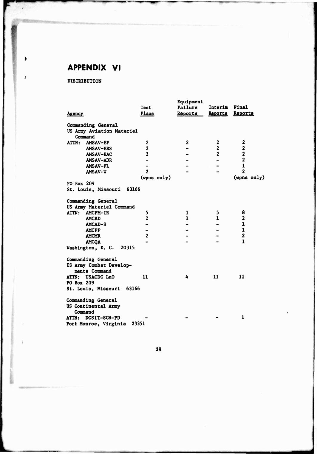
APPENDIX VI DISTRIBUTION
Equipment Test Failure Interim Final
Agency Plans Reports Reports Reports
Commanding General US Army Aviation Materiel
Command ATTN: AMSAV-EF 2 2 2 2
AMSAV-ERS 2 - 2 2 AMSAV-EAC 2 - 2 2 AMSAV-ADR - - - 2 AMSAV-FL - - - 1 AMSAV-W 2 - - 2
(wpns only) (wpns only) FO Box 209 St. Louis, Missouri 63166
Commanding General US Army Materiel Command ATTN: AMCPM-IR 5 15 8
AMCRD 2 112 AMCAD-S - - - 1 AMCPP - - - 1 AMCMR 2 - - 2 AMCQA - - - 1
Washington, D. C. 20315
Commanding General US Army Combat Develop-
ments Command ATTN: USACDC LnO 11 4 U 11 P0 Box 209 St. Louis, Missouri 63166
Commanding General US Continental Army
Comand ATTN: DCSIT-SCH-PD - - - 1 Fort Monroe, Virginia 23351
29

■■
A» —
UNCLASSTFIEü Security Classification
DOCUMENT CONTROL DATA R&D (Security clas.iHication ot title, öudy of »bstracl and indexing annotation must be entered when the overall report Is clnssllied)
I. ORIGINATING ACTIVITY (Corporate author)
US Amy Aviation Test Activity (USAAVNTA) Edwards Air Force Base, California 93523
2«, REPORT SECURITY CLASSIFICATION
Unclassified 2b. CROUP
3 REPORT TITLE
ENGINEERING FLIGHT TEST OF IKE AH-1G HELICOPTER, TO DETERMINE THE AREA OF INADEQUATE DIRECTIONAL CONTROL POWER AT 8100 POUNDS GROSS WEIGHT
4 DESCRIPTIVE NOTES (Type of report and inclusive dates)
Final Report - 4 August 1967 through 12 August 1967 5 AU THOR(S) CFirsf name, mid lie initial, leit name)
Gary C. Hall, Major, TC, US Army, Project Pilot- John R. Melton, Project Engineer
6- REPORT DATE
January 1968 7a. TOTAL NO. OF PAGES
25-
7b. NO. OF REFS
63. CONTRACT OR GRANT NO
b. PROJEC T NO.
USAAVNTA 66-06
9a. ORIGINATOR'S REPORT NUMBER(S)
N/A
9f;. OTHER REPORT NO(S) (Any other numbers that may be assigned this report)
N/A 10. DISTRIBUTION S^ATEMEN
US military agenc^ shall request thr 20315
11 SUPPLEMENTARY NOTES 12 SPONSORING Ml LM AR Y ACTIVITY
Commanding General US Army Materiel Command ATTN: AMCPM-IR Washington. D. C. 20315
1 3. ABSTR AC T
This test determined the area of inadequate directional control power of the AH-1G helicopter at 8100 pounds gross weight. The test was conducted at Grand Prairie Municipal Airport near Fort Worth, Texas, from 4 August 1967 to 12 August 1967 by the US Army Aviation Test Activity (USAAVNTA). Paced in-ground-effect (IGE) flight, hovering in winds, approaches to a spot, and arrestment of turn rates at various wind azimuths were investigated. This test proved that the AH-1G Helicopter had inadequate directional control power in winds between 8 and 13.5 knots true airspeed, with a relative wind azimuth between 170-degrees and 250-degrees. These results indicated the need for a "Warning Note" which is proposed in the report, to be included in the operator's manual alerting the operator to effects of wind velocity and direction on the IGE handling qualities. The tail rotor drive train showed evidence of rapid deterioration due to high horsepower operation during mid-test and post-test inspections. The production stability and control augmentation system configuration in the test aircraft was markedly inferior to that previously tested by USAAVNTA. Specifically roll damping was not sufficient to arrest the inherent low frequency (0.6 to 1 cps) roll oscillation of the aircraft. The VHF radio in the test aircraft became inoperative.
DD,FrJ473 UNCLASSIFIED

UNCLASSIFIED "~ Security ClaMlficatlon"
'
KEY WORDS LINK A
ROLE WT
LINK LINK C
ROLE WT ROLE WT
AH-1G Helicopter 8100 Pounds Gross Weight Inadequate Direction Control Power Warning Note Tall Rotor Drive Train Stability and Control Augmentation System Roll Damping VHF Radio
UNCLASSIFIED

■^
■
INSTRUCTIONS TO FILL OUT DO FORM 1473 - DOCUMENT CONTROL DATA (See ASPR 4-211)
*
I. ORIGINATING ACTIVITY: Enter the name and address of the contractor, subcontractor, grantee, Department of Defense pctivity or other organization (corporate author) issuing the report.
2a. REPORT SECURITY CLASSIFICATION: Enter the over- j all security classification of the report. Indicate whether
"Restricted Data" is included. Marking is to be in accord- ance with appropriate security regulations.
2b. GROUP: Automatic downgrading is specified in Doü direc- tive 5200.10 and Armed Forces Industrial Security Manual. Enter the group number. Also, when applicable, show that optional markings have been used for Group 3 and Group 4 as authorized.
3. REPORT TITLE: Enter the complete report title in all capital letters. Titles in all cases should be unclassified. If a meaningful title cannot be selected without classifica- tion, show title classification in all capitals in parenthesis immediately following the title.
4. DESCRIPTIVE NOTES: If appropriate, enter the type of report, e.^., inte-im, progress, summary, annual, or final. Give the inclusive dates when a specific reporting period is covered.
5. A'JTHORrS): Enter the name(s) of the author(s) in normal order, e.g., full first name, middle initial, last name. If militarv, show grade and branch of service. The name of the principal author is a minimum requirement.
6. REPORT DATE: Enter the date of the report as day. month, year; or month, year. If more than one date appears on the re- port, use date of publication.
7a. TOTAL NUMBER OF PAGES: The total page count should follow normal pagination procedures, i.e.. enter the tuim- ber of pages containing information.
7b. NUMBER OF REFERENCES; Enter the total number of references cited in the report.
i
8a. CONTRACT OR GRANT NUMBER; If appropriate, enter tht applicable number of the contract or grant under which the report was written.
8b, 8c, and 8d. PROJECT NUMUER: Enter the appropriate military department identification, such as project number, task area number, systems numbers, work unit number, etc,
Pa. ORIGINATOR'S REPORT NUMBER(S): Enter the official report number by which the document will be identified an.i controlled by the originating activity. This number must he unique to this report.
Pb. OTHER REPORT NUMBER(S): If the report has been assigned any other report numbers (either by the originator or by the sponsor), also enter this number(s).
10. DISTRIBUTION STATEMENT: Enter the one distribution statement pertaining to the report.
Contractor-Imposed Distribution Statement
The Armed Services Procurement Regulations (ASPR), para 9-203 stipulates that each piece of data to which limited rights are to be asserted must be marked with the followins legend:
"Furnished under United States Government Contract No. . Shall not be either released outside the Government, or used, duplicated, or disclosed in whole or in part for manufacture or procurement, without the written permission of , except for; (i) emergency repair or overhaul work by or for the Government, where the item or process concerned is not otherwise reasonably available to enable timely performance of the work, ot (11) release to a foreign government, as the interests of the United States may require; provided that in either case the release, use, duplication or disclosure hereof shall be subject to the foregoing limitations. This legend shall be marked on any reproduction hereof in whole or in part,"
If the above statement is to be used on this form, enter the following abbreviated statement:
"Furnished under U. S. Government Contract No. . Shall not be either released outside the Government, or used, duplicated, or disclosed in whole or in part for manufacture or procurement, without the written permission of , per ASPR 9-203."
DoD Imposed Distribution Statements (reference DoD Directive 5200 20 ) "Distribution Statements (Other than Security) on Technical Documents," March 29, 1965.
STATEMENT NO. 1 • Distribution of this document is unlimited.
STATEMENT NO. 2 (UNCLASSIFIED document) • This document is subject to special export controls and each transmittal to foreign governments or foreign nationals may be made only with prior approval of (fill in controlling DoD office).
(CLASSIFIED document) - In addition to security require- ments which must be met, this document is subject to special export controls and each transmittal to foreign governments or foreign nationals may be made only with prior approval (fill in controlling DoD Of (ice).
STATEMENT NO. 3 (UNCLASSIFIED document)- Each trans- mittal of this document outside the agencies of the U. S. Government must have prior approval of ((ill in controlling DoD Office).
(CLASSIFIED document) - In addition to security require- ments which apply to this document and must be met, each transmittal outside the agencies of the U. S. Government must have prior approval of (fill in controlling DoD Office).
STATEMENT NO. 4 (UNCLASSIFIED document) - Each trans- mittal of this document outside the Department of Defense must have prior approval of (fill in controlling DoD Office).
(CLASSIFIED document) • In addition to security require- ments which apply to this document and must be met. each trans- mittal outside the Department of Defense must have prior ap- proval of (fill tn controlling DoD Office).
STATEMENT NO. S (UNCLASSIFIED document) This document may be further distributed by any holder only with specific prior approval of (till in controlling DoD Office).
(CLASSIFIED document) - In addition to security require- ments which apply to this document and must be met, it may be further distributed by the holder ONLY with specific prior approval of (fill in controlling DoD Office).
11. SUPPLEMENTARY NOTES: Use for additional explanatory notes.
12. SPONSORING MILITARY ACTIVITY; Enter the name of the departmental project office or laboratory sponsoring (paying for) the research and development. Include address.
13. ABSTRACT; Enter an abstract giving a brief and factual summary of the document indicative of the report, even though it may also appear elsewhere in the body of the technical re- port. If additional space is required, a continuation sheet shall be attached.
It is highly desirable that the abstract of classified re- ports be unclassified. Fach paragraph of the abstract shall end with an indication of the military security classification of the information in the paragraph, represented as (TS), (S), (C), or (V).
There is no limitation on the length of the abstract. How- ever, the suggested length is from 150 to 225 words.
14. KEY WORDS: Key words are technically meaningful terms or short phrases that characterize a report and may be used as index entries for cataloging the report. Key words must be selected so that no security classification is required. Iden- tifiers, such as equipment model designation, trade name, military project code name, geographic location, may be used as key words but will be followed by an indication of techni- cal context. The assignment of links, roles, and weights is optional.
* U S •OVIRMMINT MINTIMOmci IM« O—tM-«M