Embed Size (px)
Citation preview
UNCLASSIFIED
AD NUMBER
LIMITATION CHANGESTO:
FROM:
AUTHORITY
THIS PAGE IS UNCLASSIFIED
AD878259
Approved for public release; distribution isunlimited.
Distribution authorized to U.S. Gov't. agenciesonly; Administrative/Operational Use; NOV 1970.Other requests shall be referred to U.S. ArmyTank Automotive Command, Warren, MI 48090.
USATAC ltr, 22 Jun 1971

5-J QQ TECHN
9
>-
O O
e-3
CAL REPORT NO. 11146
MAINTENANCE-FREE IGNITION SYSTEM
FOR THE M151 VEHICLE
NOVEMBER 1970
U.S. ARMY TANK - AUTOMOTIVE COMMAND CONTRACT NO. DAAE07-70-C-0111
D 0
D C nnnm
< JAN 5 19JI fYt jnii
J Itaanns
by NORMAN F. 8IEJA
THE PRESTOUTE COMPANY DIVISION OF ELTRA CORPORATION
Each transmittal of this document outside the agencies of the U.S. Government must have prior approval of U.S. Army Tar.k — Automotive Command, AMSTA—BSL
VEHICULAR COMPONENTS & MATERIALS LABORATORY
U.S. ARMY TANK AUTOMOTIVE COMMAND Wan
7>

TECHNICAL REPORT NO. 11146
DA-
xMAINTENANCE-FREE IGNITION SYSTEM
FOR THE Ml51 VEHICLE
FINAL REPORT
NORMAN F. SIEJA
THE PRESTOLITE COMPANY DIVISION OF ELTRA CORPORATION
TOLEDO, OHIO
November 1970
PREPARED PURSUANT TO
CONTRACT NO. DAAE07-70-C-0111
VEHICULAR COMPONENTS AND MATERIALS LABORATORY U.S.ARMY TANK-AUTOMOTIVE COMMAND
WARREN, MICHIGAN

The findings in this report are not to be construed as
an official Department of the Army position, unless so
designated by other authorized documents.
DISTRIBUTION STATEMENT
Each transmittal of this document outside the agencies
of the U.S. Government must have prior approval of U.S,
Army Tank Automotive Command, AMSTA-BSL.
DISPOSITION
Destroy this report when no longer needed. Do not
return to the originator.
The citation of commercial equipment or products in
this report does not constitute an official endorsement
or approval of the use of such commercial hardware or
products.
11
FORFVORD
This report covers work under Contract Nc. DAAB07-70-C-
0111 performed by The Prestolite Company. Division of
Eltra Corporation. Toledo. Ohio. The contract calls for
the development of a maintenance-free, solid state, capac-
itor discharge ignition syste» for the Ml 51 vehicle. The
work was administered under the direction of the Vehicular
Components and Materials Laboratory. U.S. \rary Tank Xutc-
motive Command. Warren. Michigan. The report covers work
conducted from September.1**9.to October.»97C. The Presto-
lite Company acknowledges the contributions of the Ethyl
Corporation. Ferndale. Michigan, which, as a subcontractor,
provided the engine test facilities a**d technical assist-
ance necessary to complete the pr*»grajt.

ABSTRACT
Optim-jt ignition parameters are deter.mned from dyna-
mometer tests conducted on an Ml51 military engine
eQ-jipped with a prograwrable capacitor discharge igni-
tion syste« and coaapared to a standard military igni-
tion systen. A capacitive-discharge ignition system
:s then designed tc meet the selected ignition parameters
with the purpose of producing an ignition system which
i» »si r. tc nance- free for the life of the vehicle. Vehi-
cle I«.fe is defined as SO.000 miles or 3.500 hours of
engine operation. Data collected during testing arc
\2*e£ tc she** t**e difference m performance of the two
types cf ignition system. The effects of spark energy.
spark deration, vcltage risetime and peak power are
discussed. Twelve sajrple ignition systems with opti-
mised ignition characteristics are constructed, func-
tionally tested and delivered tc USATACOK for further
life tests.

TABLE OF CONTENTS
SECTION PAGE
I . AIMS AND OBJECTIVES r 1
II. BACKGROUND 1
III. METHOD OF OBTAINING OBJECTIVES 1
A. Initial Engine Calibration 2
1. As received engine calibration 2. Precise engine calibration
B. Determining Optimum Ignition Parameters 3
C. Extended Tests 3
D. Testing Optimized Ignition System 4
E. Determination of Engine Octane Requirements . 4
F. Finalized System 4
G. Final Proof Test of Ignition 4
H. Electromagnetic Compatibility Tesc , 4
I. Cold Start Test 5
IV. RESULTS 5
A. Initial Engine Calibration 6
1. As received engine calibration 2. Precise engine calibration
B. Optimization of Spark Parameters 13
1. No load test 2. Spark gap configuration test 3. Risetime test
C. Testing Optimized Ignition System 17
D. Final Procf Testing of Sample System 19
E. Octane Number Requirement 26
F. Electromagnetic Compatibility Test 30
G. Cold Start Test 30
v

TABLE OF CONTEXTS - (Cont'd)
SECTION PAGE
V. DISCUSSION 3f
VI. CONCLUSIONS . 42
VII. RECOMMENDATIONS 4?
VI

LIS'I' OF ILLUSTRATIONS
F'igt:rc
1. As Installed Engine Calibration . . . . . . . . . . . . . . . . . . . . . . . 2. ~!bt Spark and F:.xed Carburetor., Standard
Ignition System. (Spark Adv.,F/A and Bhp)
3. ~llit Spark and Fixed Carburetor, Standard
. . . . . . . . . . . . . . 8
9
Ignition System. (~1anifold Press.,Bsfc and HC) ••••••••• 10
·-*. Ft:ll Throttle Mbt Spark and Lbt. Carburetor, s tand."l rd Iqn it ion Sys tern. • • • • • • • • • • • • • • • • • • • • • • • • • • • 11
S. Half Load Best Economy, Standard Ignition S~rstcm ........................•...•••..•.......... 12
. ~ ~0 Load Test • u. (1000 rpm) . . . . . . . . . . . . . . . . . . . . . . . . . . . . 14
7. ~0 Laad Test (2000 rpm) ............................ 15
R. No Load Test (3000 rpm) . . . . . . . . . . . . . . . . . . . . . . . . . . . . 16
9. Comparison of Surface Gap and J8 Spar~:: Plug Performance. . . . . . . . . . . . . . . . . . . . . . . . . . . . 18
10. ~fut Spark and Fixed carburetor, CD Ignition System. (Spark Adv., F/A and Mbt) ••••••••••••••••••••• 20
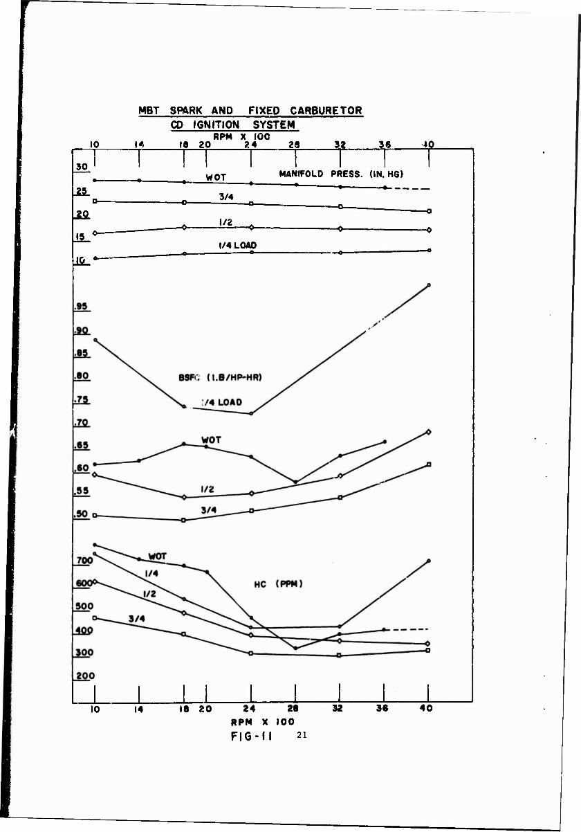
ll. ~!bt Spark and Fixed carburetor, CD Ignition System. (Manifold Press.,Bsfc and HC) •••••••••••••••• 21
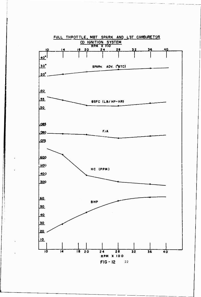
12. Pull Throttle, Mbt Spark and Lbt Carburetor, CD Ignition system. . .....••.••..•••••.••••••.•••••• 22
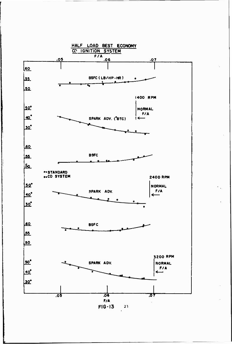
l3. Half Load Best Economy, CD Ignition System ••••••••••• 23
14. Hvdrocarbon Level Comparison, Standard and CD Ignition- Best Economy Test •••••••••••••••••••••• 24
15. ~~11 Throttle, Mbt Spark and Fixed Carburetor, Standard and Cv Ignition System •••••••••••••••••••••• 25
16. Blo~k Diagram 0f Ignition System •••••••••••••••••.••• 27
vii

r ---
LIST OF ILLUSTRATIONS -(Cont'~
Figure
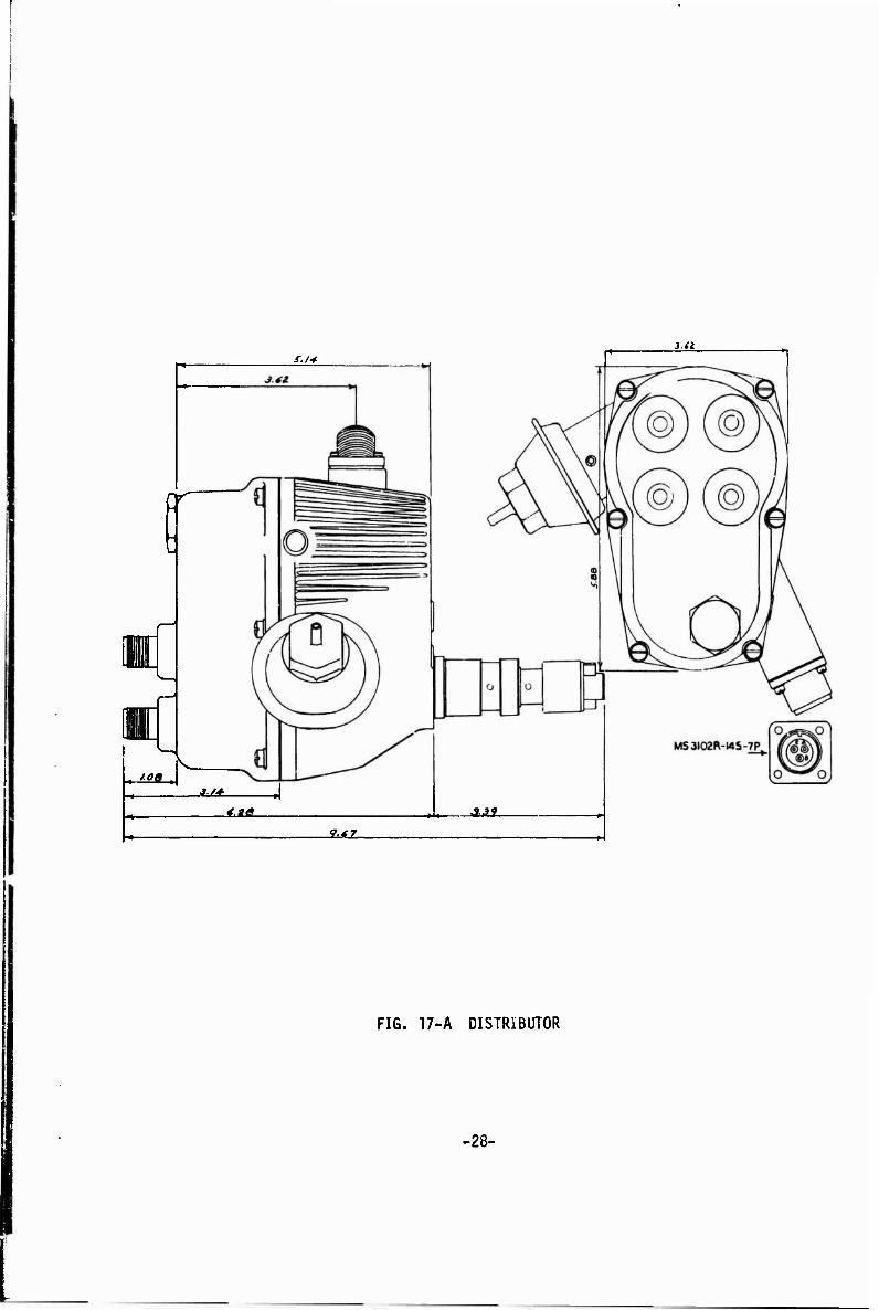
17. l\.. Distributor . . . . . . . . . . . . . . . . . . . . . . . . . . . . . . . B. Power Pack and Cable Assembly . ........... .
18. A. Electromagnetic Compatibility Test (Radiated) •••••.•••••
B. Electromagnetic Compatibility Test (Conducted) •••••••••••
19. Spark Voltage Wav~form in Laboratory ........... 20. Spark VoJtage Waveform on Engine
21. Cathode Glow . . . . . . . . . . . . . . . . . . . . . . . . . . . . . . . . . . 22. Pea~c: Power vs. Crankshaft Rotation
23. Spark Advance at Full and Part Throttle with Fixed Carburetor ••••...•••...••••••••••••
viii
28
29
31
32
34
34
37
40
44
! f,'

LIST OF TABLES
Table Pag_e
9
10
I
Engine Specifications and Operating Data ....
Full Throttle as Installed Engine Calibration
Manifold Pressure wich Mbt Spark and Fixed Carburetor
Bhp with Mbt Spark and Fixed Carburetor
Bsfc with Mbt Spark and Fixed Carburetor
Spark Advance with Mbt Spark and Fixed Carburetor
F/A with Mbt Spark and Fixed Carburetor
FID lie with Mbt Spark and Fixed Carburetor
WOT Power with Mbt Spark and Lbt Carburetor
Programmable Capacitive Discharge System • •
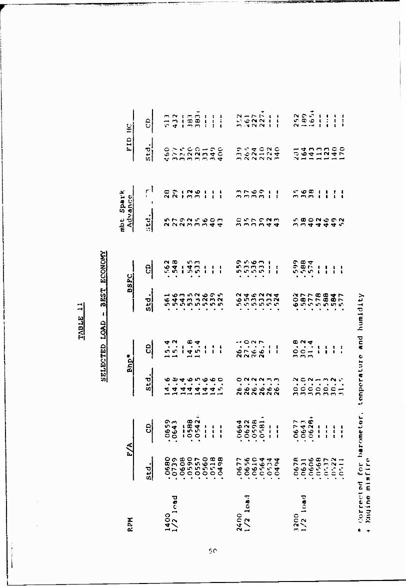
Selected Load - Best Economy
12. Manifold Pressure with Distributor Spark Advance and Fixed Carbureter.(Sample Ignition Systems).
13. Bhp with Distributor Spark Advance and Fixed Carburetor. (Sample Ignition Systems)
14. Distributor Spark Advance with Fixed Carburetor (Sample Ignition Systems)
15. F/A with Distributor Spark Advance and Fixed Carburetor. (Sample Ignition Systers)
16. Bsfc with Distributor Spark Advance and Fixed Carburetor. (Sample Ignition Systems)
45
45
46
46
47
47
48
48
49
49
50
51
52
53
54
55
IX

LIST OF TABLES (Cont'd)
Table Page
17. FID HC ith Distributor Spark Advance and Fixed Carburetor. (Sample Ignition Systemr) 56
18. Cold Start Comparison Test 57
.19. Design Specifications for Delivered Samples 58

I. AIMS AND OBJECTIVES
Tlif objective of t-.li i a project was to develop an ignition system which is canabie of being maintenance-free for the life of the vehicle on which it is installed, Vehicle life is defined as 50,000 miles of vehicle operation or 3,500 hour" of engine oper- a t i u n .
rhe system is solid state and is a two-piece assembly consisting of a distributor and an electronic power pack. In an effort to establish a universal spark plug for a]1 military engines the system utilizes annular gap spark plugs.
The system meets the basic environmental requirements of speci- fication MIL-D-13791-D, except, high temperature, which is increased to 250°F, and will not be damaged due to reversal of primary volt- age or to shorting of the secondary output.
Although this project is concerned primarily with a design for the four cylinder M151 military engine, the system incorporates design features capable of maximum commonality for use on 4, 6 and 8-cylinder spark ignition engines used in the military system.
The program concludes with the production of twelve operating sam- ples of a military, radio-shielded, contactless capacitor-discharge ignition system with ignition performance equal to or better than that of the standard ignition system.
II. BACKGROUND
The ignition system presently used consists of a conventional distributor with an integral coil mounted in a waterproof, radio suppressed housing. The usual cam, breaker points, and capacitor are used to interrupt the primary current of the coil. The second- ary voltage is distributed to the various cylinders through use of a rotor and distributor cap. A centrifugal mechanism is used for sparx advance.
This system requires considerable maintenance and parts replace- ment and exhibits poor spark plug performance and life. The sys- tem also requires the stocking of many individual parts as well as spark plugs with a large number of different insulators for many different heat ranges. A system is desired which is main- tenance-free and has capabilities of better spark plug performance and spark plug life compatible with vehicle life.
III. METHOD OF ACHIEVING OBJECTIVES
To achieve a maintenance-free ignition system with a lifetime compatible with engine life, the contactless capacitive-discharge type of ignition system is a logical choice. Such a system com- pletely eliminates maintenance problems associated with engine timing and adjustment and replacement of distributor points. The electronic sensor which is used to replace the distributor

points is permanently adjusted at the time of manufacture of the distributor. Timing variations, due to wear of the rubbing block and contacts of the distributor points, are eliminated. As a result, engine timing, once set, becomes a permanent adjustment and is fixed for the life of the distributor.
A capacitive discharge system of the type used in this project features a fast spark plug voltage risetime and high available voltage over the entire speed range of the engine. This type of system can fire spark plugs which are fouled and have wide gaps, a feature necessary to assure long spark 'plug life. The use of annular spark plugs should further enhance spark plug life, due to the greater effective electrode area common to plugs utilizing this gap configuration. An additional benefit to the use of annular gap spark plugs is the possibility of establishment of a universal heat range for spark plugs used on military engines.
To properly design a capacitive discharge ignition system to meet the requirements of this project, it was necessary to identify those characteristics of an electric spark which would properly ignite the fuel-air mixture in the combustion chamber of the engine. Since the new ignition system must perform at least as well as the existing system, it was also necessary to measure the performance of the standard ignition system to determine base line requirements. Optimum spark characteristics were determined so they could be built into the new ignition system.
To accomplish these objectives, project activity moved through the following steps:
A. Initial Engine Calibration
To conduct the initial engine calibration test as well as all subsequent testing, evaluation and optimization of the new ignition system, an M151 military engine was mounted on an electric dynamometer equipped with a Ward-Leonard control system. To gather valid and repeatable data, various engine supply temperatures were held within the following limits:
Intake air — 100°F + 5°F Cooling water — 180°F ± 5°F Lubricating oil — 250°F maximum
Engine fuel was Indoline 30 and lubricating oil was Kavoline 10W-30. Exhaust hydrocarbons, CO, C02 and 0~ were measured during critical engine conditions to permit detection of poor combustion or misfire. These measurements also served as an excellent cross-check on fuel-air ratios as determined by direct fuel and air measurements.
1. 7.s-Received Engine Calibration. This test was conducted with the standard ignition system and standard carbure- tor. At engine speeds from 1000 RPM to rated power speed in 400 RPM increments and including the speed at
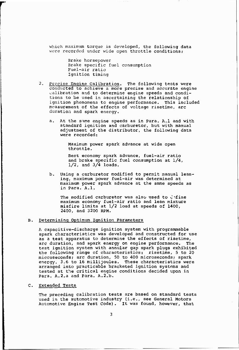
which maximum torque is developed, the following data wore recorded under wide open throttle conditions:
Brake horsepower Brake specific fuel consumption Fuel-air ratio Ignition timing
2. Precise Engine Calibration. The following tests were conducted to achieve a more precise and accurate engine calibration and to determine engine speeds and condi- tions to be used in ascertaining the relationship of ignition phenomena to engine performance. This included measurement of the effects of voltage risetime, arc duration and spark energy.
a. At the sMe engine speeds as in Para. A.l and with standard ignition and carburetor, but with manual adjustment of the distributor, the following data were recorded:
Maximum power spark advance at wide open throttle.
Best economy spark advance, fuel-air ratio and brake specific fuel consumption at 1/4, 1/2, and 3/4 loads.
b. Using a carburetor modified to permit manual lean- ing, maximum power fuel-air was determined at maximum power spark advance at the same speeds as in Para. A.l.
The modified carburetor was also used to C->fine maximum economy fuel-air ratio and lean mixture misfire limits at 1/2 load at speeds of 1400, 2400, and 3200 RPM.
B. Determining Optimum Ignition Parameters
A capacitive-discharge ignition system with programmable spark characteristics was developed and constructed for use as a test apparatus to determine the effects of risetime, arc duration, and spark energy on engine performance. The test ignition system with annular gap spark plugs exhibited the following range of characteristics: risetime, 5 to 20 microseconds; arc duration, 50 to 400 microseconds; spark energy, 3.6 to 16 millijoules. These characteristics were arranged into practicable bracketed ignition systems and tested at the critical engine conditions decided upon in Para. A.2.a and Para. A.2.b.
C. Extended Tests
The preceding calibration tests are based on standard tests used in the automotive industry (i.e., see General Motors Automotive Engine Test Code). It was found, however, that
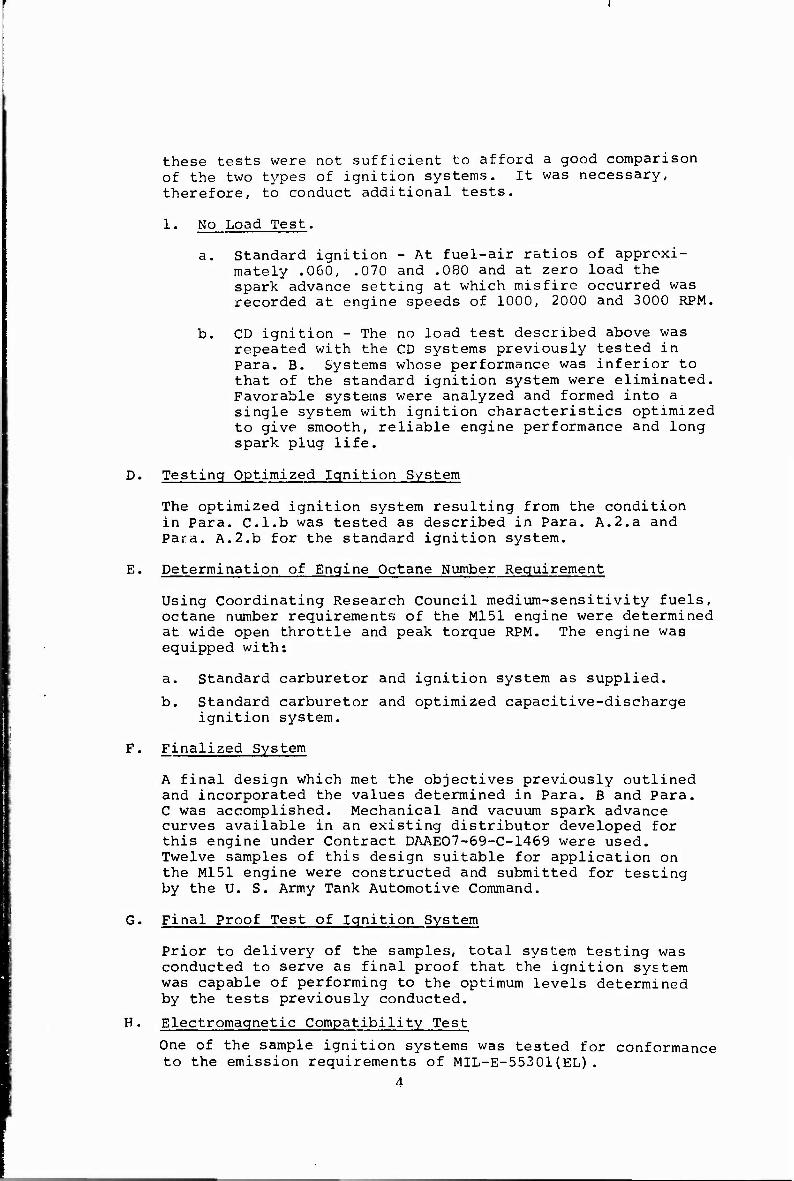
these tests were not sufficient to afford a good comparison of the two types of ignition systems. It was necessary, therefore, to conduct additional tests.
1. No Load Test.
a. Standard ignition - At fuel-air ratios of approxi- mately .060, .070 and .080 and at zero load the spark advance setting at which misfire occurred was recorded at engine speeds of 1000, 2000 and 3000 RPM.
b. CD ignition - The no load test described above was repeated with the CD systems previously tested in Para. B. Systems whose performance was inferior to that of the standard ignition system were eliminated. Favorable systems were analyzed and formed into a single system with ignition characteristics optimized to give smooth, reliable engine performance and long spark plug life.
D. Testing Optimized Ignition System
The optimized ignition system resulting from the condition in Para. C.l.b was tested as described in Para. A.2.a and Para. A.2.b for the standard ignition system.
E. Determination of Engine Octane Number Requirement
Using Coordinating Research Council medium-sensitivity fuels, octane number requirements of the M151 engine were determined at wide open throttle and peak torque RPM. The engine was equipped with:
a. Standard carburetor and ignition system as supplied.
b. Standard carburetor and optimized capacitive-discharge ignition system.
F. Finalized System
A final design which met the objectives previously outlined and incorporated the values determined in Para. B and Para. C was accomplished. Mechanical and vacuum spark advance curves available in an existing distributor developed for this engine under Contract DAAE07-69-C-1469 were used. Twelve samples of this design suitable for application on the M151 engine were constructed and submitted for testing by the U. S. Army Tank Automotive Command.
G. Final Proof Test of Ignition System
Prior to delivery of the samples, total system testing was conducted to serve as final proof that the ignition system was capable of performing to the optimum levels determined by the tests previously conducted.
H. Electromagnetic Compatibility Test
One of the sample ignition systems was tested for conformance to the emission requirements of MIL-E-55301(EL).
A

I. Cold Start Test
The contract covering work on this project did not specify extensive environmental testing. In addition, all tests and comparisons were conducted with the engine under running con- ditions. Speculation arose over the ability of the CD system to start the engine under cold weather conditions. The heavy choking required under these conditions results in poor fuel mixing and distribution. It was decided to compare the engine starting performance of the two types of ignition systems at -25°F. This is considered a worst case since it is the lowest temperature at which starting is attempted with- out the use of starting aids.
The engine, batteries and fuel supply were placed in a cold box and three separate starting attempts were made with each type of ignition system. The crankcase oil was MIL-L-10295 (5W). The crankcase was drained and refilled after each start. The fuel used was wintergrade gasoline with the fol- lowing specifications:
RVP: 12 to 13 psi 50% ASTM distillation point: 190 to 210°F API gravity: 60 to 63
Each starting attempt was made with clean spark plugs and fully charged batteries. Ambient temperature, engine crank- case temperature and battery electrolyte temperature were monitored. The engine was allowed to soak until all thermo- couples indicated temperatures between -25°F and -30°F.
During each starting attempt the following data were recorded at cranking and running conditions:
Required spark plug voltage (plug firing) Available spark plug voltage (plug disconnected) Battery voltage, open circuit and during cranking Cranking current Cranking RPM Cranking time
The following instrumentation was used during the cold start- ing tests:
Sanborn Model 858-1000 voltage and current recorder Leeds and Northrup Speedomax W temperature rtcorder Tektronix 545B oscilloscope with high voltage probe
IV. RESULTS
Test results are reported in the order in which tests were performed, With the exception of the test for engine octane requirements and some no-load tests added at a later time, all tests with the stand- ard ignition system were completed before any engine work with the capacitive-discharge systems began. Test results, along with any pertinent comment, will be presented in this section first
for the standard ignition system and secondly for the various capacitive-discharge systems. In the following section the test results of each type of system and their relationship to each other will b° discussed.
A. Initial Engine Calibration
To achieve the objective previously outlined (i.e, a main- tenance-free ignition system), it was necessary to measure the performance of the M151 engine with standard carburetor and distributor. Data resulting from these measurements served as a standard for comparison in evaluating the per- formance of the new ignition system.
The engine, equipped with generator, battery, flywheel, exhaust pipe and complete standard ignition system was mounted on the dynamometer. An orifice was placed in the exhaust pipe to simulate the muffler's back pressure. A second carburetor, modified to permit manual mixture control, was used on tests where adjustment of fuel-air ratio was necessary. The fuel- air ratio öS measured on the fixed carburetor was accepted as being representative of all carburetors used on this engine. To prevent erratic injection of fuel into the engine, the vacuum ports to the accelerator pump on these carburetors were plugged.
The dynamometer was equipped with instrumentation to measure brake horsepower, spark timing, fuel and intake air consump- tion. Exhaust emissions of hydrocarbons (flame ionization detector), carbon dioxide (C02), carbon monoxide (CO) and oxygen (02) were measured to detect poor combustion and mis- fire and to determine fuel-air ratio. A Tektronix Model 3 21 oscilloscope and high voltage probe were used to measure spark characteristics on the engine. One spark plug on the engine was equipped with an adapter to facilitate measurement of available voltage, risetime, spark plug breakdown voltage, arc voltage and spark duration.
The measurement of spark current was accomplished by using special ignition coils on which the ground side of the second- ary was available at a separate terminal. With this type of ignition coil a current sensing resistor of very low ohmic value can be placed between the secondary terminal and ground for convenient measurement of current through the entire secondary circuit.
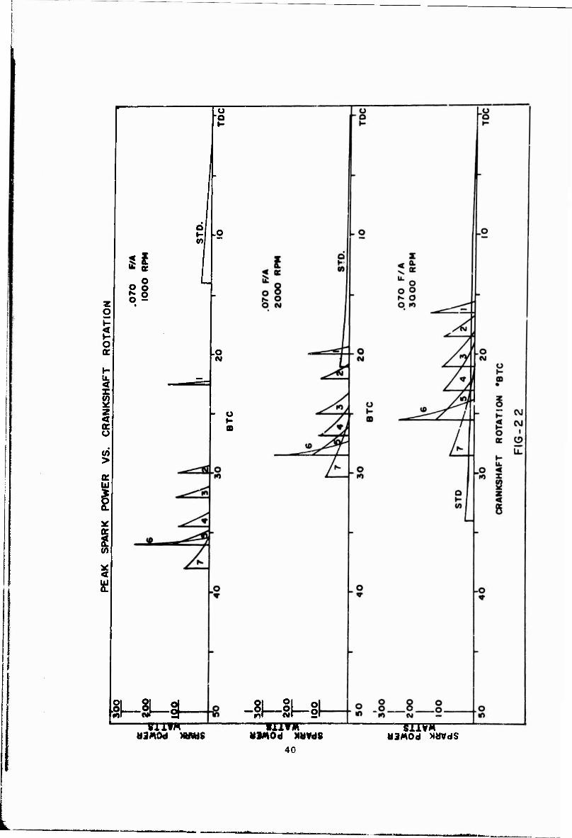
Concurrent voltage, current and time measurements make it possible to calculate energy dissipated in the spark. To assure the accuracy of this method of energy determination a special calorimeter was constructed and calibrated to measure spark energy directly. Spark energy was simultane- ously measured in the laboratory by the calorimeter and by the oscillographic method and the results were found to correlate within ±10%. Specifications and operating data for the M151 engine are shown in Table 1.

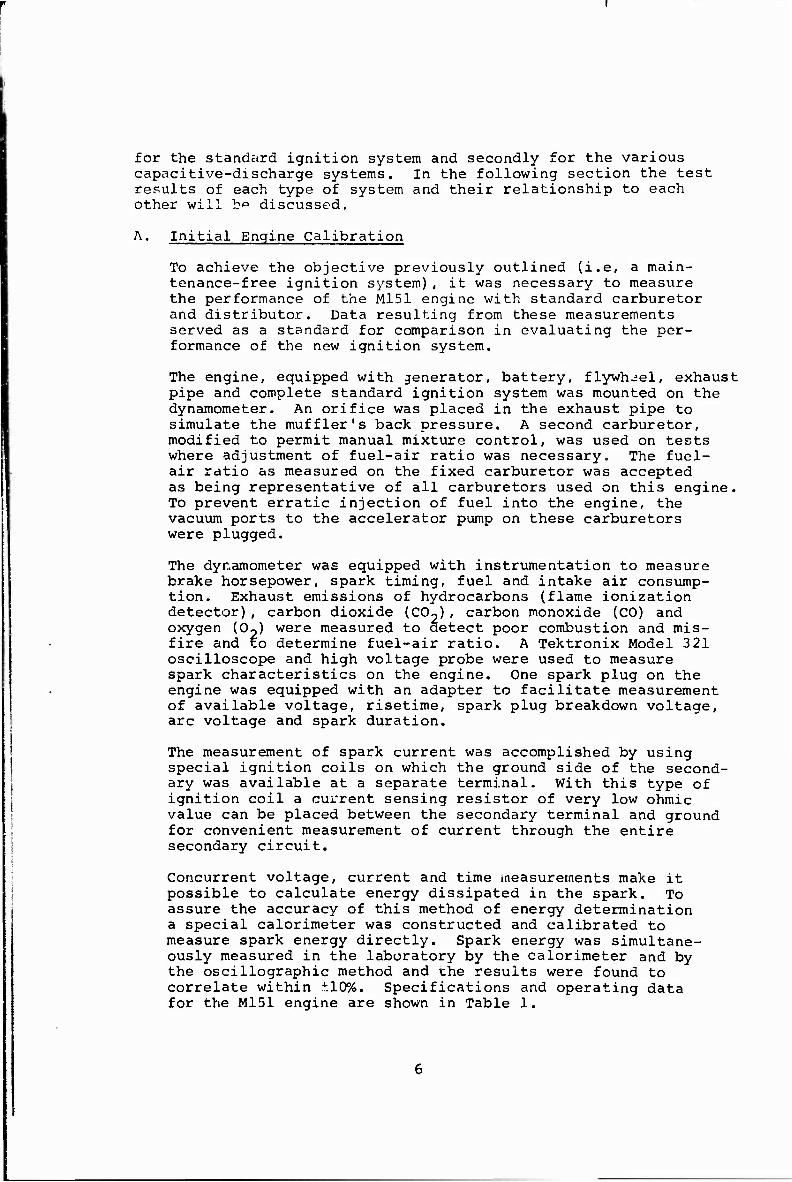
As-Received Engine Calibration. This test is representa- tive of full throttle performance over the speed range of the engine as installed in a vehicle. The stock car- buretor and ignition system were used. The engine was run at wide open throttle at speeds from 1000 to 4000 RPM in 400 RPM increments. Distributor spark advance and automatic carburetor F/A were used. The reuults of this test "are tabulated in Table 2 and shown graphically in Figure 1.
Precise Engine Calibration. In the following tests the distributor and carburetor were manually controlled to measure the performance of the engine at optimum spark timing and carburetion conditions. Manual control of the distributor and carburetor make it possible to define areas of critical engine operation. At these critical operating conditions, the engine is more sensitive to changes in ignition characteristics. This type of testing also offers greater repeatability of test results.
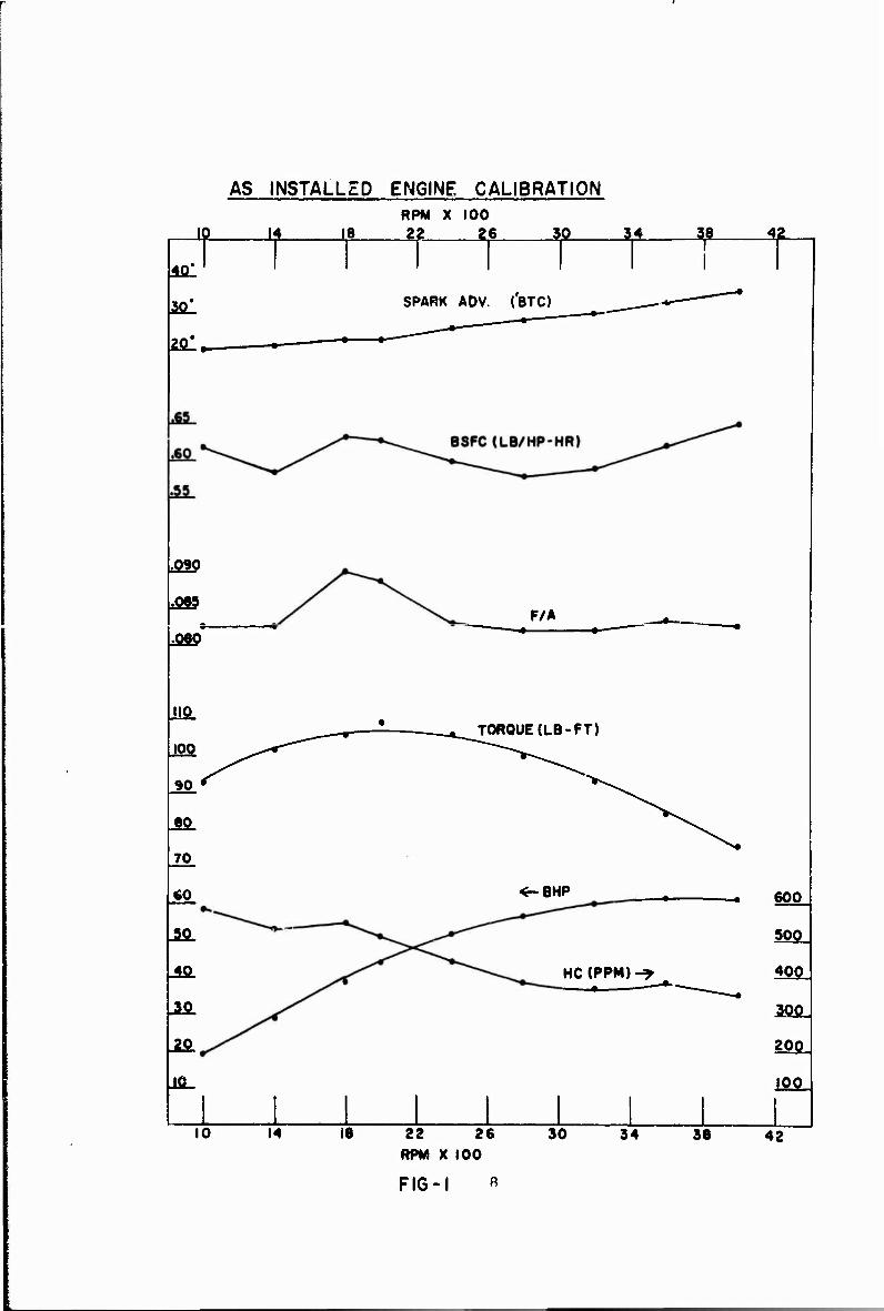
a. Full and part throttle power with mbt spark and fixed carburetor - This test indicates performance of the power plant with automatic carburetion, but with spark timing manually adjusted for mbt (minimum spark advance for best engine torque). The test is the same as the "As-Received Calibration" test in para. A.l, ex- cept for manual spark control and additional operation at 1/4, 1/2, and 3/4 of the wide open throttle beam load (torque). The results of these tests are shown in Figures 2 and 3.
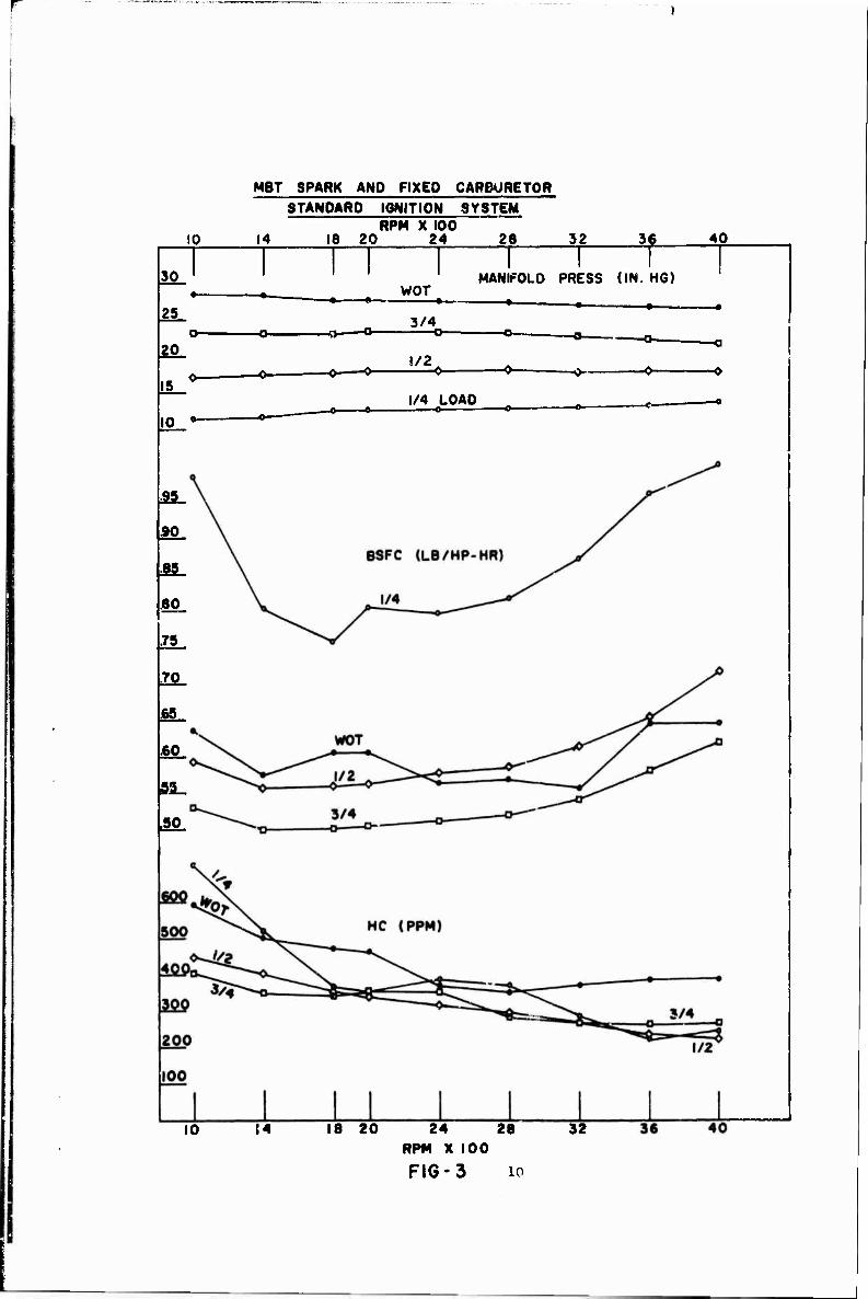
b. Full throttle power with mbt spark and lbt (leanest fuel-air ratio for best engine torque) carburetor - This test is user» to determine the effect of ignition and carburetion changes on full throttle power and fuel consumption. It is used here to determine the effects of various ignition characteristics on maxi- mum power and fuel consumption. Similar tests were conducted with a capacitive-discharge ignition system which had variable energy, risetime and arc duration capabilities. The results of this test for the stand- ard ignition system are shown in Figure 4.
c. Half load, best economy - The purpose of this test is to obtain information on part load economy, which can be used to compare the performance of the two types of ignition systems. The engine was run at 1400, 2400 and 3200 RPM at 1/2 maximum beam to simu- late road load conditions. F/A is manually adjusted leaner until a minimum value of brake specific fuel consumption is found or misfire occurs. The load and speed are held constant as the carburetor is leaned out. Test results are shown in Figure 5.
Figure 5 shows that as the fuel-air mixture is leaned out, hydrocarbon output decreases to its lowest value
AS INSTALLED ENGINE CALIBRATION
f 18 RPM X 100 22 26 30 34 38 f 401
aal
2ül
SPARK ADV. ('BTO
■090
.088 F/A
IIP
100
90
80
70
CO
J50_
_4P_
JS_
-2P_
JflL
TOROUE(LB-FT)
«-BHP
HC(PPM)-* ■ ———"
600
500
400
IfiOj
200
IfioJ
10 14 18 22 26 RPM X 100
FIG-1 A
30 34 38 42

10
MBT SPARK AND FIXED CARBURETOR STANDARD IGNITION SYSTEM
RPM XIOO 14 18 20 24 26
1/2 LOAD
A-4 RPM X 100
FIG-2 9
10
MBT SPARK AND FIXED CARBURETOR STANDARD IGNITION SYSTEM
14 RPM X 100
18 20 24 28 32 f 40
30
25
2P_
I5_
10 •"
WOT MANIFOLD PRESS (IN. H6)
• ■ -
3/4
!/2
1/4 LOAD o
—a
-O
Sft_
SO
SSL
*g_
.75
.70
65
60
5S_
SQ.
10 14 18 20 24 28 RPM X 100
FIG-3 10
32
FULL THROTTLE MBT SPARK LBT CARBURETOR
■J£- _UL STANDARD IGNITION SYSTEM
ie 20 T T T JW- 4P-
SSL
2a!.
SPARK ADV (feTC)
699
,060
PIS
700
figg/
Sfio
400
300
F/A
HC(PPM)
■ *-
U "~24 21 RPM X 100
FIG-4 ii
10 14 32 s« 40

HALF LOAD BEST ECONOMY "STANDARD IGNITION SYSTEM .05 .06
F/A
.07
.60
■55
£0_
40J
Jfil
*- flSfC (LB / HP- HR)
1400 RPM
4_S0_
400
350
300
SPARK AOV. (*BTC)
.60
.50
SSL * 2400 RPM
350
300
250
200
SPARK AOV.
.60
.55
.50
«0*
BSFC
SPARK AOV.
:öT 1 !o1 F/A
FIG.-5
3200 RPM
25Q.
200
150
100
Ir
at about .056 F/A and then begins to rise until mis- fire occurs at about .05 F/A or 20:1 A/F. This is extremely lean for a four cylinder engine and repeat- ability was poor at F/A leaner than .06. Normally, a four cylinder engine is not operated leaner than 17:1 because of poor mixture distribution. The engine's fuel mixture as received was automatically carbureted at .067 F/A or 15:1 A/F at 1/2 load. See Figure 2.
B. Optimization of Ignition Parameters
With the completion of the initial calibration, the next phase of this project involved the determination of optimum ignition parameters. It was also the intent here to ascertain the effects of spark voltage risetime, arc duration and spark energy on engine performance. To accomplish this objective, a capacitive-discharge ignition system with programmable spark characteristics was used. The system was equipped with controls for the adjustment of spark energy, duration and risetime.
The controls were adjusted to yield seven different ignition systems with the characteristics listed in Table 10. Also shown in Table 10 are the characteristics of the standard ignition system. These seven systems with energy levels ranging from 3.6 to 16.0 millijoules were subjected to the half load economy test, Para. A.2.c, at 1400 RPM.
It was found that all of the CD. systems, including the low- est energy system, performed as well as the standard ignition system making impossible a comparison of the two types of ignition systems. In addition, setting the F/A mixture at discrete ratios proved very time consuming because of the laborious process involved in raking accurate 7/A measure- ments. It became apparent that another method of comparison must be found. It was decided that spark advance, rather than F/A, should become the variable. Spark advance adjust- ments can be made and measured almost instantaneously and the erratic operation associated with operating at very lean mixtures is eliminated.
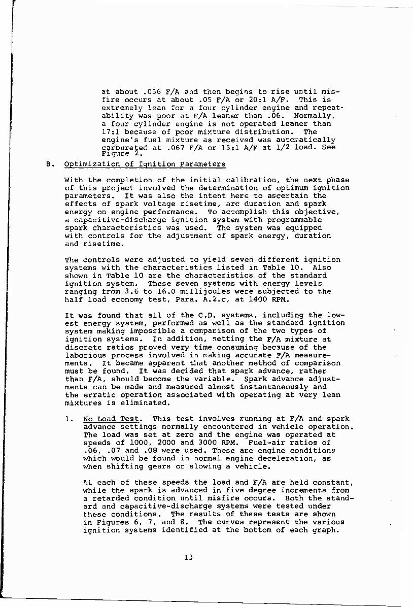
1. No Load Test. This test involves running at F/A and spark advance settings normally encountered in vehicle operation. The load was set at zero and the engine was operated at speeds of 1000, 2000 and 3000 RPM. Fuel-air ratios of .06, .07 and .08 were used. These are engine conditions-- which would be found in normal engine deceleration, as when shifting gears or slowing a vehicle.
M. each of these speeds the load and F/A are held constant, while the spark is advanced in five degree increments from a retarded condition until misfire occurs. Both the stand- ard and capacitive-discharge systems were tested under these conditions. The results of these tests are shown in Figures 6, 7, and 8. The curves represent the various ignition systems identified at the bottom of each graph.
13

NO LOAD TEST
_6fi
IOOO RPM 39.7 *AIR FLOW
ZERO LOAD
•LB/HR
_5fi.
_4Ä
o
bl U z > a
t
JQ
20
10
.065
SYSTEM NO
I 2 3 4 5 6 7 S
.060 J. .070 .065 .060
F/A SPARK SPARK DURATION ENERGY 50 US 3.6 MJ
100 us 5.0 MJ (50 US 6.4 MJ 200 US 9.6 MJ 200 US 13.2 MJ 100 us I2.8MJ 400 US 16.0 MJ 2000 US 3O0MJ (STO. SYSTEM)
FIG-6 14

NO LOAD TEST
60
2000 RPM 71* AIR FLOW ZERO LOAD
*LB/HR
50
40
30 00
I*
lii o z < Q 20 NO MISFIRE
REGION
a. CO
.085
SYSTEM NO
I 2 3 4 3 6 7 S
.060
SPARK DURATION SOUS IOOUS ISO US
200US 200US IOOUS 400US 2000 us
.073 .070 .065 .060
SPARK ENERGY 3.6 MJ 5.0MJ 8.4MJ
9.6 MJ 13.2 MJ I2.6MJ
16.0 MJ 30.0MJ (STO. SYSTEM)
F/A
FIG.- 7 15
NO LOAD TEST
60
3000 RPN IOO*AIR FLOW ZERO LOAD
*LB/HR
50
_4P_
o
ffi 0
_ap_ Ul o z < > Q <
OT
20
MISFIRE REGION
NO MISFIRE REGION
/
.015 .0 80 .075 .070 .065 .060
SYSTEM SPARK SPARK ?/l NO DURATION ENERGY
1 50US 3.6 MJ 2 100 MS 5.0 MJ 3 ISO us 8.4 MJ
4 200 US 9.6 MJ 5 200JJS I3.2MJ 6 100 MS I2.8MJ 7 400JJS I6.0MJ S 2000JJS 30.0MJ (STD. SYSTEM)
FIG-8 16

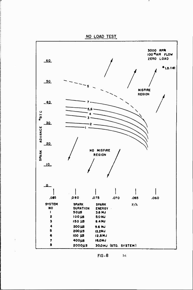
2. Spark Gap Configuration Test. Figure 9 shows the same test conducted with J-8 type spark plugs and two of the CD ignition systems. The tests were conducted using CD system number 6 at 1000 and 2000 RPM. The purpose of these tests was to determine the effects of spark plug gap configuration on engine performance. Spark plugs used with capacitive-discharge systems are of the resiotor- less type. Because of the relatively high spark currents involved in CD systems, compared to standard ignition systems, they cannot tolerate resistor type spark plugs without significant loss of spark plug energy. The J-8 spark plug was chosen for this test because its heat range approximates that of the original equipment.
It can be seen that surface gap spark plugs offer an oper- ational advantage. Generally, the surface gap plugs can be operated at more advanced spark settings than spark plugs with J type gaps. Reasons for this improvement are open to conjecture. A probable explanation may lie in the fact that the surface gap spark plug has a wider and more exposed spark gap.
Operation with J-8 spark plugs shows the same tendency for a retarded spark requirement at higher engine speeds that the surface gap plugs show. It is apparent that this tendency is not due to gap configuration.
3. Risetime Test. To determine the effect of spark voltage risetime on engine performance, risetime was varied from a minimum of five to a maximum of twenty microseconds (without changing the spark plug energy or spark duration) at the engine conditions where misfire began. No improve- ment or deterioration of engine performance could be detected at these critical engine conditions, indicating that risetime variations in this range have no measurable effect on engine performance. This test is probably unique in that it has been typically reported that changes in risetime have only been accomplished with corresponding changes in spark duration and spark energy. Therefore, what has often been reported as improvements in ignition due to slower risetime were undoubtedly due to inadvertent changes in spark energy.
The ability of a spark having a fast voltage risetime to fire fouled spark plugs is well known. However, this test was concerned only with the investigation of risetime on ignition performance where fouling was not a problem.
C. Testing Optimized Ignition System
A prototype ignition system embodying optimum spark charac- teristics determined in Para. B of this section was constructed. The optimized ignition system contained the following charac- teristics:
17
COMPARISON OF SURFACE GAP AND
J8 SPARK PLUG PERFORMANCE
-ftfl-
JUL
40
30
o 20
t
1000 RPM
39.7*AIR FLOW
ZERO LOAD
L9/HR
.065
(t
CO
-ftfl.
JÄ-
Jfi_
JML
2000 RPM 71* AIR FLOW
ZERO LOAD
LB /HR
/
FIG- 9 18

Spark energy -- 8 millijoules Spark duration — 120 microseconds Risetinu: — 8 microseconds Available voltage — 15 kilovolts, minimum
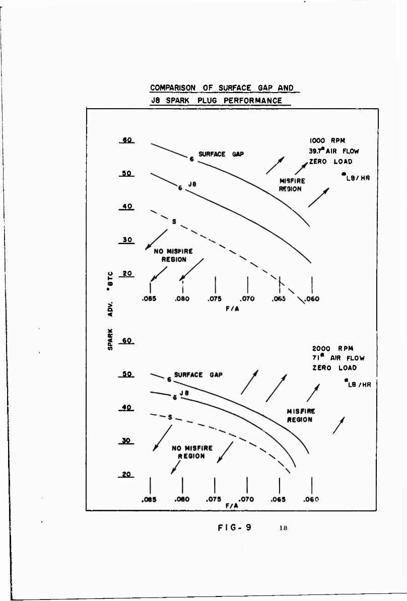
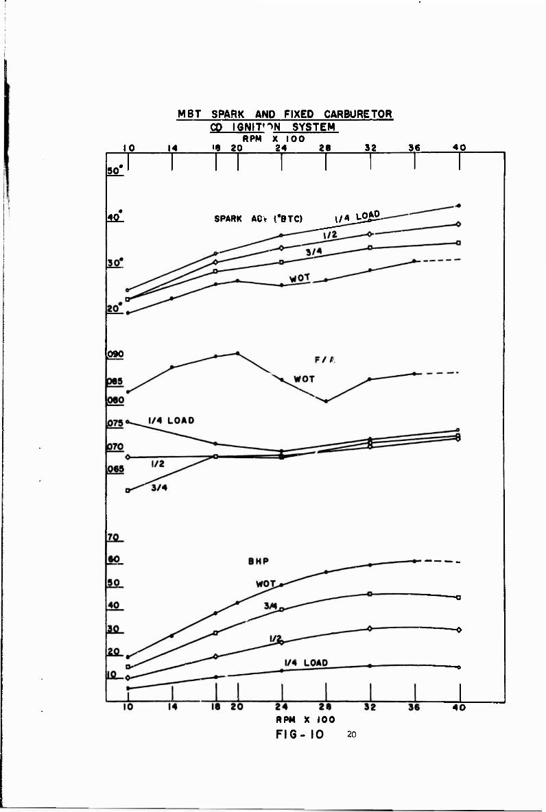
The system, using surface gap spark plugs, was tested as described in Para. A.l.a and Para. A.l.b of Section III for the standard ignition system. Test results can be seen in Figures 10 through 15. The results are also tabulated in Tables 3 through 10. For comparison purposes, data reflected in Figures 2 through 5 for the standard ignition system are also shown in these tables.
The tables show that engine performance is the same for both types of ignition system. Small differences seen in the measurements are attributable to limiLations of the instrumen- tation and difficulties in reproducing identical operating conditions from test to test. The build-up of deposits in the engine is one such difficulty. This can be seen in Figure 14, where hydrocarbon levels are seen to be higher for the CD system. Data for the standard system were col- lected at the beginning of the program, while the CD system hydrocarbon levels were measured near the end. Therefore, the absolute values are not significant? however, the trends indicated by the data show the behavior of both systems to be essentially the same. Namely, that hydrocarbon output increases at richer fuel mixtures and decreases at higher engine speeds. Although both systems perform equally well at normal fuel-air ratios, the standard ignition system can be operated at leaner mixtures without misfire. Engine performance, however, is degraded at these overly lean mix- tures.
Another indication of the effects of deposit build-up on hydro- carbon output can be seen in Table 9. This test was conducted on the standard and CD ignition systems within a few engine hours of each other and no practical difference can be seen in the data recorded for both systems.
The performance of the standard and CD ignition systems is graphically compared in Figure 15 at full throttle with mbt spark and fixed carburetor. Bhp and mbt spark timing is the same for both systems. Bsfc is seen to be slightly higher for the CD system. This discrepancy was traced to a missing gasket in the carburetor during the CD test. As a result the carburetor was running slightly rich as can be seen by the F/A trace in Figure 15. With a fixed carburetor the standard and CD F/A traces would be the same.
D. Final Proof Testing of Sample Systems
Twelve sample ignition systems, each consisting of a power pack, a distributor, interconnecting cable and shielded sur- face gap spark plugs were constructed and assembled. The spark characteristics of the optimized ignition system were incorporated in the samples.
19
10
MBT SPARK AND FIXED CARBURETOR CD IGNIT'^N SYSTEM
RPM X 100 14 '9 20 24 28 32 36 40
50'
lisl SPARK AD\ t*BTC) l/«J^£2-
090
ia 20 24 2a RPM X 100
FIG- 10 2o
40
10
MBT SPARK AND FIXED CARBURETOR
14
CD IGNITION SYSTEM RPM X 100
18 20 24 28 J&- 36 40
30 i
14. i
WOT
3/4
1/2
I/4L0A0 -•—
MANIFOLD PRESS. (IN. HG) • ,
10 14 18 20 24 28 RPM X 100
FIG -11 2i
32 36 40
FULL THPQTTLE. MBT SPARK AND LBT CARBURETOR CD IGNITION SYSTEM RPM XTCO "
10 14 18 20 2 4 28 3 2 36 40. f 40"
SPARK ADV. (*BTC)
.60
.55
.50
BSFC (LB/HP-HR) ■ * -
•085
.080.
.075
F/A
10 14 18 20 24 26 RPM X 10 0
FIG - 12 22
32 36 40
j.«0_
HALF LOAD BEST ECONOMY CDJGNITION SYSTEM
.09 F/A
.06 •07
BSFC(LBZHP-HR) •
n- *—
1400 RPM
NORMAL F/A
SPARK ADV. fBTC)
.60
30*
•-STANDARD •.CD SYSTEM
BSFC
_• ft.
SPARK ADV.
2400 RPM
NORMAL F/A
30.
M_
.50
BSFC
ISO-
I^Oj
Uar
3200 RPM
NORMAL F/A
4 .05 .01^ F/A
FIG-13 23

HYDROCARBON LEVEL COMPARISON, STANDARD AND CD IGNITION-BEST ECONOMY TEST
<5Q
400
350
300
1400 RPM 1/2 LOAD
• 'STANDARD
•■CD SYSTEM
NORMAL F/A
400
350
300
250
200
2400 RPM 1/2 LOAD
NORMAL F/A
250
200
150
100
3200 RPM t/2 LOAD
NORMAL F/A
.0 5 .06 F/A
rIG- 14
.or
24

FULL THROTTLE . MBT SPARK AND FIXED CARBURETOR STANDARD AND CD IGNITION SYSTEM
IC 14
i r 18 20
RPM X IOC 24 28 32 38 40
STANDARD
BSFC (LB/HP-HR)
STANDARD
70
30.
40
.20
10. {
Jfi. I
"lO
BHP
14 18 20 24 28 RPM X 100
FIG -15
32 38 40

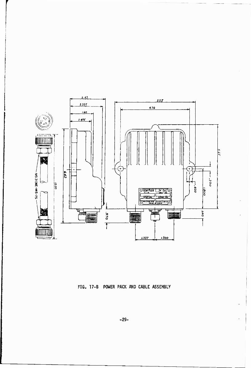
The power pack contained all of the electronic circuitry with the exception of the ignition coil and the electronic sensor, which triggered the spark. These were integrally mounted within the distributor. The distributors were equipped with mechanical and vacuum spark advance and were adjusted to a spark advance curve used in an existing distributor developed for this engine under another contract. This curve differs from the mbt spark advance data determined for this engine by providing more than the optimum advance, particularly at part throttle. This may be expected to cause a higher emis- sion level without significantly affecting engine performance. A block diagram of the ignition system appears in Figure 16, while outline drawings of the components appear in Figures 17A and 17B.
Test results for the sample systems are listed in Tables 12 through 17. Tests on the sample systems were conducted only at operating conditions that were considered to be critical. This was done to make maximum use of the dynamometer time scheduled by the testing laboratory. For comparison, test results for the standard ignition system with mbt spark timing are also shov/n. The standard carburetor was used throughout.
The data show that the sample systems meet the objectives set forth previously and exhibit the same spark characteristics as the optimized ignition system. The hydrocarbon data in Table 16 show misfire occurring at high speed, light load conditions. The term misfire, as used in the data and text, refers to a condition more accurately described as poor burn- ing of the fuel mixture and not to a condition where ignition does not take place. It is seen on the FID recorder as small, but rapid rises (blips) in hydrocarbon output and is a bor- derline condition beyond which complete misfire would eventu- ally occur. The engine's output performance is not affected by this condition.
Octane Number Requirement
The full throttle octane requirement for the CD and standard ignition systems was determined at 2000 RPM. In this test spark timing was slowly advanced from a retarded condition until knocking began. Tne spark timing was then recorded to indicate the knock sensitivity with the fuel being used. Following are the results obtained with three different octane fuels:
Spark Advance When Knock Began Fuel
Octane
86 88 90
Std. CD
24° 24° 28° 28° 34° 32°
Full throttle mbt spark advance for this engine at 2000 RPM is 25°.
26

BLOCK DIAGRAM OF IGNITION SYSTEM
POWER PACK
TRIGGER
SWITCH
CONVERTER
CABLE
IGNITION / SWITCH
H
DISTRIBUTOR
BATTERY
SENSOR
IGNITION COIL
ROTOR
SPARK PLUGS
FIG-16 27
3.(1 S./4-
-
/ga ■«■ • »—k.
,■?•/+
<gg *l Jt,i£- _2L£Z_
FIG. 17-A DISTRIBUTOR
•28-
2.43
2.223"
* Lü£- 1 t_- 1,"
* £
N ■©-
*L o
■y^f
4.70
y~Y r n T ri r ■
3»I6NIT0R ! |V. OC\" r_Eiii» a»'»!
Mf«m. MWW
O^ MAPI m IA*.A. lO
A337 1.300
k.
--Q X
0
6>
o
FIG. 17-B POWER PACK AND CABLE ASSEMBLY
■29-

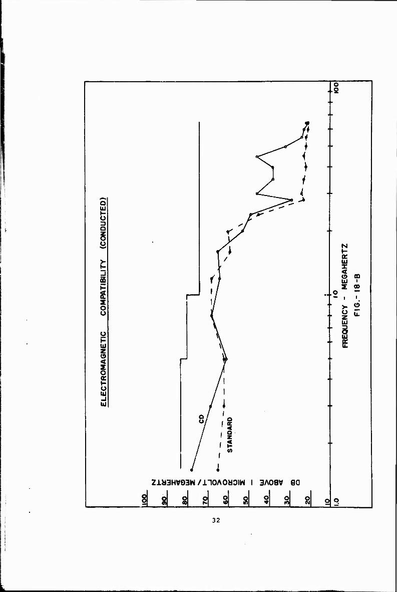
F. Electromagnetic Compatibility Test
An electromagnetic compatibility test per MIL-E-55301(EL) was conducted on the standard and capacitive-discharge sys- tems. Both systems were operated on the same vehicle. The standard ignition system used was the original equipment on the vehicle used in this test. Test results for both systems are compared in Figures 18A and 18B. The data show that both systems met the allowable limits for conducted and radiated emission with no significant differences evident. Test equip- ment consisted of a Singer noise and field intensity meter set, model NF-205.
G. Cold Start Test
A cold start comparison test was conducted using one of the sample CD ignition systems and the standard system furnished with the engine. The prupose of this test was to prove the starting capability of the CD ignition system at very low temperatures and to compare its performance to that of the original equipment. To assure the reliability of the results the test was repeated twice for each ignition system. The cold start test results appear in Table 18.
The data show that three successful starts were made with each ignition system. The data recorded for both systems are similar. Required spark plug voltage during cranking was slightly higher for the CD system. This is believed to be due to the difference in spark gap sizes of the plugs used. The surface gap spark plug has a .05 inch gap while the standard plug is gapped at .03 inches. The cranking time (4.2 to 9.4 seconds) is an indication of the amount of time required to move fuel into the combustion chambers. Availa- ble spark plug voltage during crank and run was measured by restarting the engine with the number one spark plug wire removed from the plug. The data show that the? performance of both systems is comparable and no cold starting difficul- ties are anticipated.
V. DISCUSSION
A discussion of the performance of various ignitJon systems should perhaps be prefaced by a discussion of the ignition spark itself. The terms used to describe various components of a spark lead to some confusion due to differences in interpretation and means of measurement. An attempt is made here to clarify the meanings- of the terms as they are used in the text and to explain the condi- tions of measurement. Spark phenomena noted in the laboratory while calibrating the instruments,and on test ignition systems used on the engine,will also be discussed.
Risetime, as referred to in the text, is the time required for the available spark voltage to rise from 10% to 90% of its maxi- mum open circuit value. Unless specifically mentioned, it does not refer to time required for the voltage to reach the breakdown
30

*% 8 O
\
Je* •rjjr
3- O o
f^ Ä ^Ja* Q y* Ul *» ** j
>- --'*" / < 5 «* ÜC
—«. / N \-
Ul X
>■
\\ g < H w 1 ZJ Z 2 s / \
,o 1 o < * 5 c Q.
3 z Ul
O o Ul
>7 K ü // u. P ff UJ z 1/
8 § ff
K II ü UJ
1/ o _l // ,*■"
Ul 1 1
1
/ o /\ ff
/ v £ / v« / l
Z1M3HV93W / nOAOHOIW 1 3A08 V 80
§8l8ls|8l8lSlsläc j t
31
o 2
«5 ^
^^ *>
<z < 1 * ■
y1 ' «C 4
o *^5 > bJ _^«•^i*" 1- "*3r o D ^ / O
8 <y O /[ N
»-
>- i / UJ »- X 3 o f)
< (!) CD UJ i
P S oo $
i / -- .o — — 1 1
o 1/ - >. 6
Ü \ 2 *■ Ul
o • § Ul \ • E z (9 < z o or / 1 H / 1 Ü / 1 UJ / 1 -1 / 1 UJ / i
8/ 18 / <
/ «»
/ ;
ZJL«3HV93W/nOAOaOIW I 3A08V 80
i *! d s| s| si §1 s| a o q
32
value of a spark gap. Spark duration is the time from the initia- tion of breakdown of the gas or vapor between the electrodes until the cessation of current through the ionized material in the gap. The breakdown at the beginning of the sparJ', which is accompanied by a bright flash of light, is of short duration and is usually a very small part of the tc^al spark energy. In automotive igni- tion, what is usually referred to as the inductive or arc portion of the spark occupies the largest part of the duration period. The terms, spark and arc, are used here in the sense in which they appear in automotive literature and not in the literal or classi- cal r;ense. The breakdown mentioned previously is often referred to as the capacitive portion of the spark since it represents the discharge period of the distributed secondary circuit capacitance. Refer to Figure 19.
All laboratory measurements of the CD ignition coils were made with the ignition coil working into a parallel load of 150 pico- farads and 100 kilohms. The capacitive portion of the load represents the capacitance of the spark plug and the shielded spark plug lead on the engine. The resistive portion simulates a fouled spark plug. The development and testing of the program- maDle CD ignition system was carried out with various types and configurations of spark gaps in an effort to gain a better insight into the nature and behavior of a spark. Some observations are set forth here which may be of interest to others engaged in similar or related pursuits.
Although the same CD test ignition system was used in both cases, maximum spark energies and spark durations measured in the labor- atory differed greatly from those measured on the engine. Spark energies as high as 60 millijoules and spark durations as long as one millisecond were obtainable in the laboratory, while 16 millijoules and 400 microseconds were the maximums observed on the engine. The disparity is due to differences in the type of load seen by the ignition coil. The load differences are the result of variations in spark gap configuration, spark environ- ment and the addition of the series gap at the distributor rotor. These load variations have a large effect on the amount of stored energy transferred to the spark. The voltage drop across a spark plug (surface gap) with the engine running averaged 90-100 volts during the inductive portion of the spark. In the laboratory, using pointed electrodes, voltage drops as low as 40 volts were measured across the spark gap.
The two main factors which appear to determine this sustaining voltage during the inductive portion of the spark are spark gap size and electrode temperature. There are other factors of course which indirectly affect the sustaining voltage through a change in one or both of these parameters. In general, an increase in spark gap size results in a higher sustaining voltage and lower spark current while the result of an increase in electrode tem- perature is a lower sustaining voltage and a higher current.
Electrode configuration shows a marked affect on the breakdown voltage of a spark gap. For a given spark gap size the break- down voltage is much lowei with pointed electrodes than with
33

SPARK VOLTAGE WAVEFORM IN LABORATORY
5-6 KV- -BREAKDOWN
</>
2fifiL.
< 100
60 ARC DURATION (US)
FIG-19
Ä"
SPARK VOLTAGE WAVEFORM ON ENGINf:
4-12 KV-
20 40 60
ARC DURATION (US)
FI6-20
34

large blunt electrodes, and conversely for a given breakdown voltage pointed electrodes will yield a spark gap or permissible spark length several times that possible with blunt electrodes. It is also true that due to the poorer heat dissipating or heat sinking qualities of the pointed electrode, higher overall elec- trode temperat'ires are reached with this configuration. It is not the intent here to lead into a detailed analysis of the spark phenomena (for that is not the purpose of this project), but rather to show the complexities involved in the determination of the arc sustaining voltage and hence the amount of stored energy transferred to the spark gap. it has been observed that for a given amount of stored energy in the primary circuit of the igni- tion coil, a lower arc sustaining voltage results in a higher average spark current and a longer spark duration.
Care must be taken when relating laboratory observed phenomena to the actual spark occurrences in the combustion chambers of an engine. For although the aforementioned effects are surely present, they are modulated by the environment in which the spark functions. There are considerable differences in pressure and temperature as well as turbulence of the gas mixture within the gap inside the engine compared to a bench test gap. They are the result not only of normal compression with the cylinder, but also of the burning and expanding gases. These environmental effects can easily be seer with an oscilloscope during the inductive portion of the spark. Figures 19 and 20 depict spark voltage and current waveforms as they appear in the laboratory and on a running engine. Except for the environment at the spark plug gap, the operatxn<7 conditions are the same in both cases. In Figure 19 the spark is taking place at room temperature and atmospheric pressure, which are relativst'.' low and constant. The sustaining voltage tends to be lower a.v more constant and the spark is of longer duration.
Figure 20 shows the sustaining voltage fluctuating widely during the duration of the arc. The spark energy content is also lower in Figure 20, primarily due to a decrease in spark duration. It may be thought that because of the high temperatures known to be present during combustion, a lower sustaining voltage should be seen on the engine. This is not the case, however, and the explanation may lie in the fact that the combustion chamber is flushed with a fresh and turbulent mixture of fuel and air prior to each ignition.
It was mentioned previously that spark energy levels as high as 60 millijoules were obtained in the laboratory. These high levels were possible only when a phenomenon known as negative glow or cathode glow appeared on the surface of the negative electrode at a point where the spark took place. The glow, which appeared a pale purple in color, rose from the surface of the electrode to a thickness of approximately 0.01 inch and covered an area at least several times the uiameter cf the spark column. The area of the glow seamed to be dependent on the teir.p*>-?ture of the electrode. The glow could be made to appear and iticrear« in size by externally increasing the temperature of the electrode- Blowing cool air over the electrode caused the glew to disapprar.
35
In a similar way, it was possible to make the glow appear by using an electrode of a size and shape which would not allow the rapid dissipation of heat, thereby allowing the electrode terux -ature to build up without external aid. The ability to produo the glow was affected by pressure. As the pressure was increased it became difficult to produce the glow. This may explain the failure tc observe the phenomenon on the engine.
An important property of the glow is its ability to affect a large voltage drop across the spark gap. Voltage drops as high as 400 volts were observed while the glow was present. The appearance or disappearance of the glow was rapid as if it were switched from one state to the other. No significant difference in peak spark current was observed when the glow appeared, although there was a reduction in the duration of the spark. However, the proportions were such that an increase in total spark energy, often more than 100%, was realized. See Figure 21. The study of the glow was conducted without use of the series rotor gap to maximize the amount of energy available at the spark. Unfortunately, much time could not be spent on the investigation of this type of spark since the design of the engine and spark plugs are such that its use on the engine is precluded.
In this discussion of test results little comment is required regarding calibration of the M151 engine with the standard or original ignition system, except to say that it is a straight- forward, medium compression engine which is quite tolerant it. its ignition requirements. It is this tolerance v/hich necessi- tated the introduction of additional tests designed to search out engine conditions critical enough to afford a reliable com- parison of the various ignition systems of interest.
During the search for optimum ignition parameters a number of things of interest came to light. Among these was the discovery that all the CD systems tested, including the lowest energy sys- tem of 3.6 mi Hijoules, performed as well as the standard igni- tion system at low speeds and leaner than normal fuel mixtures. Because of poor fuel mixing and distribution this is an area where capacitive-discharge systems, with thexr usually short spark durations, are traditionally outperformed by the long duration Kettering type systems. This improvement is believed to be due to the combination of higher peak ignition power of the capacitive-discharge ignition system and annular gap spark plugs, which have slightl; larger and more exposed gaps.
As previously mentioned, the standard automotive tests did not provide a reliable means for comparison of ignition performance. In, 3e tests are based primarily on maximum power and best fuel economy. In these areap no discernible difference in performance was noted, regardless of the system used. Testing conditions on the dynamometer were near ideal and to choose ignition charac- teristics arbitrarily seemed unwise. To^ low an energy level might result in marginal performance due to small amounts of energy loss in service, while too high an energy level could cause excessive erosion of the spark plug electrodes and early system failure. It was decided to provide a system with more than twice the minimum energy as a reasonable compromise,
36
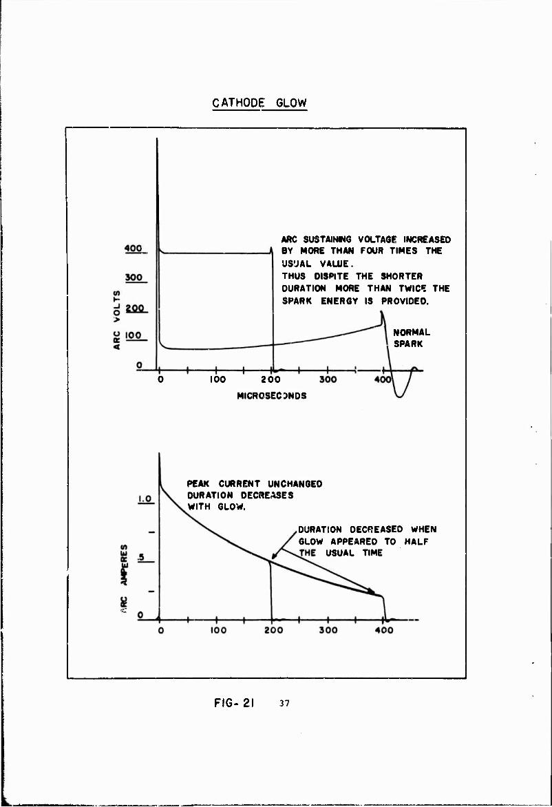
CATHODE GLOW
ARC SUSTAINING VOLTAGE INCREASED BY MORE THAN FOUR TIMES THE USUAL VALUE. THUS OISPITE THE SHORTER DURATION MORE THAN TWICE THE SPARK ENERGY IS PROVIDED.
NORMAL SPARK
100 200
MICROSECONDS
PEAK CURRENT UNCHANGED DURATION DECREASES WITH GLOW.
DURATION DECREASED WHEN GLOW APPEARED TO HALF
USUAL TIME
FIG- 21 37

The no-load test was found to be a convenient method of gauging the performance of the various ignition systems, as this is when the engine is most sensitive to ignition changes. This test simulates actual vehicle operation in the decelerating mode. The engine is operated at zero load and at three discrete ratios near the F/A encountered in normal engine operation. The spark is slowly advanced from a retarded no-misfire condition until mis- fire occurs. The performance of the various systems are seen in Figures 6, 7 and 8. Two things are immediately apparent. The ability to operate at advanced spark settings shows a dependency on total spark energy and also on spark duration. The part that each of these characteristics plays is difficult to determine from the data available. The data for the CD systems tend to show that an increase in total spark energy allows a more advanced spark setting; yet, at low and medium speeds (Figures 6 and 7) the standard ignition system with at least twice the energy of any of the CD systems cannot be advanced as far. From this it can be deduced that not only the total energy is of importance, but also the rate at which it is released into the spark.
From the theory of minimum sustaining combustion volume it is postulated that for a given engine condition a certain minimum volume of fuel (fuel-air mixture) must be ignited (burned) before ignition becomes self-sustaining. The minimum volume is that amount of burning fuel necessary to release sufficient heat in the volume of burned gases to balance the amount of heat lost to the surrounding unburned fuel, while raising it to the combustion temperature. If this minimum balance is not reached, ignition is quenched and the remainder of the fuel is left unburned. Ignition of the minimum volume is initiated through the spark which must furnish sufficient energy (heat) to continue the burn- ing process until the balance of heat stored to heat lost is reached, after which the burning process sustains itself. Total spark energy must be sufficient to achieve not only this balance, but also to overcome the heat losses to the spark plug itself. These losses are manifest in the electrodes and insulator of the spark plug.
It is conceivable that a spark of high energy content, but low rate of energy release (long spark duration), might not result in successful ignition of the fuel charge. For a given energy level an increase in the duration of a spark will result in lower peak spark power and a lower temperature distribution in the ignition volume. Too low peak power plus the steady heat loss to the surrounding media will not allow the balance pre- viously mentioned to be achieved before the spark expends itself. Conversely, if the spark duration is shortened while maintaining a constant energy level high peak powers and temperatures are the result.
1. R. T. Lovrenich, J. T. Hardin, "Electrical to Thermal Con- version in Spark Ignition," SAE Paper No. 670114, January, 1967.
38
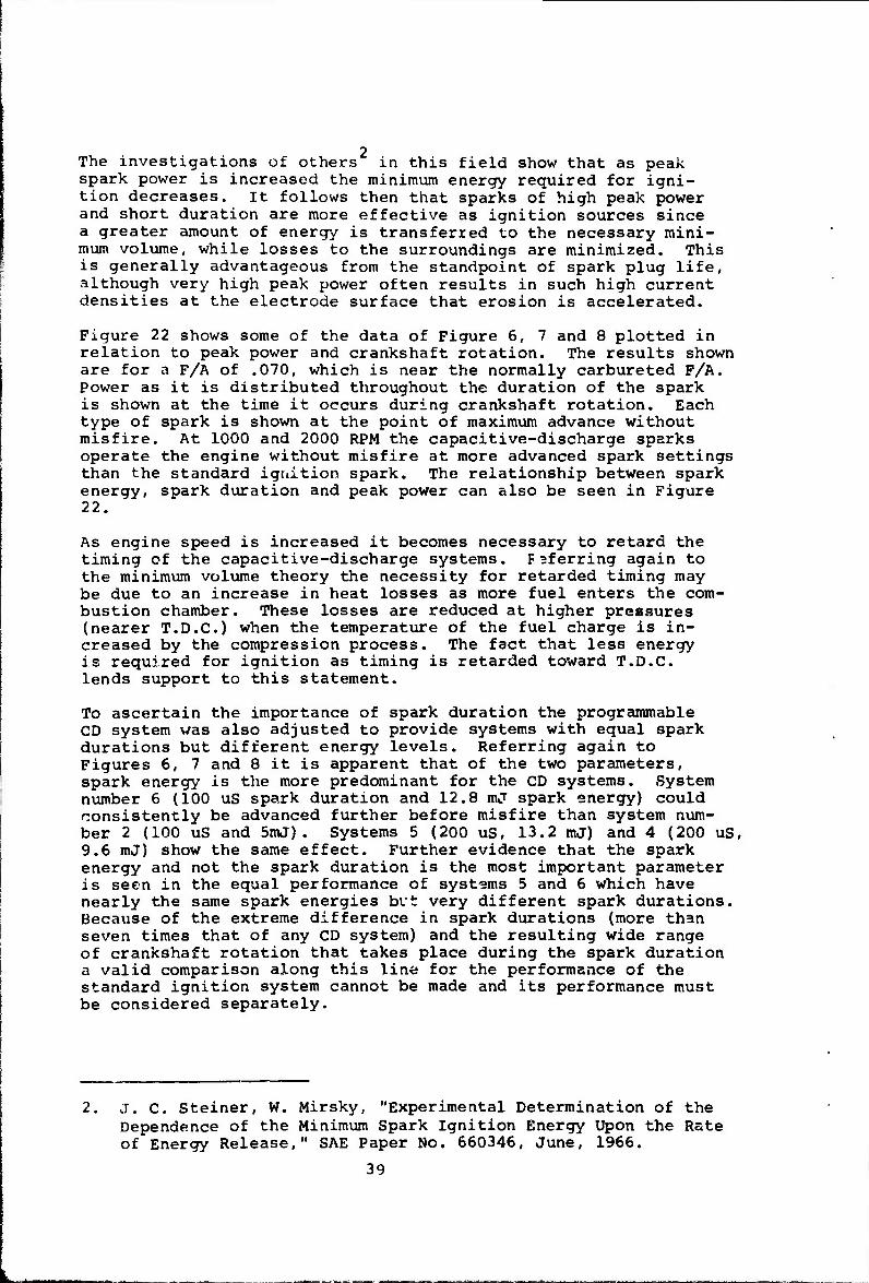
2 The investigations of others in this field show that as peak spark power is increased the minimum energy required for igni- tion decreases, it follows then that sparks of high peak power and short duration are more effective as ignition sources since a greater amount of energy is transferred to the necessary mini- mum volume, while losses to the surroundings are minimized. This is generally advantageous from the standpoint of spark plug life, although very high peak power often results in such high current densities at the electrode surface that erosion is accelerated.
Figure 22 shows some of the data of Figure 6, 7 and 8 plotted in relation to peak power and crankshaft rotation. The results shown are for a F/A of .070, which is near the normally carbureted F/A. Power as it is distributed throughout the duration of the spark is shown at the time it occurs during crankshaft rotation. Each type of spark is shown at the point of maximum advance without misfire. At 1000 and 2000 RPM the capacitive-discharge sparks operate the engine without misfire at more advanced spark settings than the standard iguition spark. The relationship between spark energy, spark duration and peak power can also be seen in Figure 22.
As engine speed is increased it becomes necessary to retard the timing of the capacitive-discharge systems. F3ferring again to the minimum volume theory the necessity for retarded timing may be due to an increase in heat losses as more fuel enters the com- bustion chamber. These losses are reduced at higher pressures (nearer T.D.C.) when the temperature of the fuel charge is in- creased by the compression process. The fact that less energy is required for ignition as timing is retarded toward T.D.C. lends support to this statement.
To ascertain the importance of spark duration the programmable CD system was also adjusted to provide systems with equal spark durations but different energy levels. Referring again to Figures 6, 7 and 8 it is apparent that of the two parameters, spark energy is the more predominant for the CD systems. System number 6 (100 uS spark duration and 12.8 mj spark energy) could consistently be advanced further before misfire than system num- ber 2 (100 uS and 5mJ). Systems 5 (200 uS, 13.2 mJ) and 4 (200 uS, 9.6 mJ) show the same effect. Further evidence that the spark energy and not the spark duration is the most important parameter is seen in the equal performance of systems 5 and 6 which have nearly the same spark energies but very different spark durations. Because of the extreme difference in spark durations (more than seven times that of any CD system) and the resulting wide range of crankshaft rotation that takes place during the spark duration a valid comparison along this line for the performance of the standard ignition system cannot be made and its performance must be considered separately.
2. j. C. Steiner, W. Mirsky, "Experimental Determination of the Dependence of the Minimum Spark Ignition Energy Upon the Rate of Energy Release," SAE Paper No. 660346, June, 1966.
39
u
Lo
z o
i o QC
1 g CO >
cc hi
IC K
52
I- Ü
en
<
a-s-a —snfw—
-§|—S|—si "1IITW
MAOd XNVdS 40
SliVM tfSMOd »WdS

The anomaly noted in a previous section of this report concerning the conflictinq behavior of the CD and standard ignition systems is shown here. The data of Figure 22 and Figures 6, 7 and 8 show that the standard ignition system, unlike the CD ignition systems, has the ability to operate at more advanced spark timing as engine speed is increased. What the data do not show and what is not known is at what point,during the duration of a spark, ignition becomes self-sustaining. The capacitive-discharge sparks, which have short durations, make it possible to fix ignition timing within a few degrees of crankshaft rotation. The standard igni- tion spark with its long duration occupies 30 degrees of crank- shaft rotation at 3000 RPM. The spark begins at 44° B.T.C. and ends at 14° B.T.C, entirely bracketing all of the CD systems tested. Figure 22 shows that at all engine speeds the standard ignition spark terminates at less than 20° B.T.C, where energy requirements for ignition are quite small. It is felt that at high engine speeds,the data indicate an advance in spark timing that does not actually correspond to an advance in ignition timing for the standard ignition system.
Achievement of the goal of a maintenance-free ignition system requires that spark plug life be greatly extended. To accomplish this, spark energy must be kept to a minimum to reduce electrode erosion. Although engine performance was satisfactory with spark energies as low as 3.6 millijoules, the probability of marginal performance dictated a somewhat higher value. It was concluded that a spark energy of 8 millijoules was sufficient to provide reliable performance under all operating conditions. The spark duration was set at 120 microseconds to keep peak power high and electrode heat losses at a minimum. Risetime of the avail- able voltage is 8 microseconds (2KV/uS) to provide for fouled plug firing capability. A minimum available voltage of 15,000 volts is specified in the contract. The highest required spark plug voltage during engine operation on the dynamometer was observed to be 12,000 volts. During cold cranking, however, the required spark plug voltage rose to 15,000 volts. To assure reliable starting at cold temperatures, the sample ignition systems provide an available output voltage that increases with decreasing temperature. The available voltage during cold crank- ing was typically 22,000 volts as shown in Table 18.
Twelve sample ignition systems embodying these characteristics were constructed and individually tested on the engine. All systems met the performance requirements and compared favorably with the standard ignition system. There is excellent uniformity of characteristics among the twelve sample systems. Design specifications for the sample systems are shown in Table 19.
A cold start comparison test between the standard and CD ignition systems shows both systems capable of successfully starting the engine at -25°F. The starting technique appeared to be less critical with the capacitive-discharge system. The engine ran and accelerated smoothly after the initial firing. Some diffi- culty in maintaining an engine runn_ng condition after initial firing was ncted with the standard system. Although choke and throttle adjustments were more critical with the standard
41

system, three successful starts were obtained with each type of ignition system.
VI. CONCLUSIONS
The ML51 engine with carburetion and ignition timing adjusted for maximum power and best economy performs equally well with the standard and capacitive-discharge systems. Mbt timing and bsfc were the same for each system. Fuel-air ratio for best torque (lbt) was also the same. Comparable performance was achieved with spark energies as low as 3.6 millijoules. Although an energy level as low as this is not considered desirable, it is an indication of the relatively small amount of energy required by the engine. Cold starting, variations in the capacitance of ignition leads and spark plugs, various losses in service, etc., dictate a higher energy level. Eight millijoules was chosen as the best compromise for the energy level.
Operating the engine at zero load provides an engine condition of low fuel density where ignition performance becomes critical. Testing under these conditions does not provide a measure of engine performance, but it does simulate a decelerating mode which is an actual vehicle condition. Advancing the spark timing until misfire occurs at low fuel densities offers a convenient and practical method of comparing various ignition systems. Present interest in the reduction of exhaust emissions indicates the significance of this type of testing.
Total spark energy does not completely describe the ability of a spark to properly ignite the fuel-air mixture. Consideration must be given to peak power (the rate at which energy is released into the spark). Data obtained from low density tests show that a spark of low energy, but high peak power and short deration, is more effective than one of high energy, low peak power and long duration. Low peak power and a long spark duration suggest a low rate of energy release.
The long duration standard ignition spark occupies approximately 30 degrees of crankshaft rotation at 3000 RPM. The low density tests show that at this speed it is probable that ignition (self- sustaining) takes place late in the spark, at retarded ignition timing, where energy requirements are low. Thus at low energy release rates it is believed that spark timing and ignition timing are not the same.
The performance of a spark ignition engine is a product of its mechanical design. Maximum performance will be achieved if the fuel charge in the combustion chamber is ignited at the proper time and the only requiremenb of the spark is that it initiate self-sustaining combustion. This is a requirement adequately met by the standard ignition system and explains why no improve- ment in performance could be seen when the capacitive-discharge system was used. After prolonged use, however, difficulties with the standard ignition system arise, which do affect engine performance. They are the result of distributor point wear, spark plug fouling and electrode erosion.
42

The value of the contactless capacitive-discharge system lies in its ability to minimize or eliminate these difficulties. The electronic sensor, which replaces the distributor points, elimi- nates the problems of point wear and adjustment, while the fast risetime spark provided by this system greatly reduces the effect of plug fouling on proper ignition and allows the use of wider spark gaps. With this system less spark energy is required for reliable ignition which is helpful in controlling electrode erosion. The short duration of the capacitive-discharge spark permits the use of annular gap spark plugs for greater system longevity.
These advantages plus the use of solid state components and con- servative design combine to yield an ignition system which will be reliable and maintenance-free for the life of the vehicle.
VII. RECOMMENDATIONS
There is evidence to indicate that ignition (self-sustaining) does not always take place at the beginning of the spark. A comparison of the misfire characteristics of the standard and CD ignition systems at zero load indicates an apparent delay in ignition, not fully understood, which appears to be determined by the peak power of the spark and the condition of the fuel-air charge in the combustion chamber at the moment of spark initiation. A program designed specifically to determine the causes and effects of this delay would provide information useful in the design of ignition and carburetion systems which provide lower exhaust emis- sion levels while maintaining maximum power and fuel economy.
A distributor without vacuum advance is recommended for the M151 engine. Use of vacuum advance will raise the level of exhaust emissions without providing significant performance advantages and it will, of course, add to the complexity and cost of the system. Although the samples were equipped with vacuum advance as required by contract, operation with centrifugal advance only, can be achieved by blocking the vacuum line. Vacuum and centri- fugal advance curves for the system are shown in Figure 23.
43

a < O
a x
X
UJ _J f- I- o or
o:
AOV XUtus 44
Table 1
ENGINE SPECIFICATIONS AND OPERATING DATA
Enqi.no model Number of cylinders Compression ratio
Ml 5 4 7.5 (published) 7.38 (measured clean)
Displacement 141.5 cubic inches Horsepower *60°F air (published) 71 @ 4000 RPM Intake air 100°F ± 5"F Cooling water 160°F + 5°F Lubricating oil Havoline 10W-30 250°F max.
Fue 1 Octane requirement Spark Plugs Basic ignition timing Pen nt gap Backpressure
Indolene 30 83 J plug .030 inch gap (shielded) 6° btdc 9 400 to 500 RPM .017 to .022 inches 6.0 inch Hg
Table 2
FULL THROTTLE AS INSTALLED ENGINE CALIBRATION
RPM TORQUE Bhp* Bsfc F/A A/F Spark
Advance HC(FID)
PPM
1000 93 19.i .619 .0826 12.1 20° 585
1400 102 28.9 .584 .0826 12.1 21° 536
1800 106 38.76 .639 .0900 11.1 23° 546
2000 109 44.0 .630 .0880 11.4 23° 512
2400 106 51.9 .600 .0831 12.0 26° 444
2800 100 57.2 .580 .0822 12.2 28° 384
3 200 93.5 60.2 .590 .0822 12.2 30° 370
3600 84.5 61.5 .620 .083 5 12.0 33° 385
4000 75.7 G1.3 .650 .0827 12.1 36° 355
Corrected for barometer, temperature and humidity.
45

TABLE 3
MANIFOLD PRESSURE* WITH MBT
SPARK AND FIXED CARBURETOR
Beam WOT 3/4
Std. CD
1/2 1/4
System Std. CD Std. CD Std. CD
RPM 1000 28.45 28.11 23.20 23.80 17.20 16.80 11.50 11.23
1400 28.29 28.01 23.00 17.60 11.70
1800 27.83 27.81 23.00 23.40 17.80 18.03 12.60 12.23
2000 27.75 27.60 23.40 18.00 12.60
2400 27.45 27.40 23.30 23.20 18.20 18.23 12.70 12.63
2800 27.35 27.10 23.20 18.20 12.80
3200 27.05 26.80 22.80 22.40 17.90 17.90 13.00 12.48
3600 26.85 26.41 22.20 18.00 13.20
4000 26.65 21.70 21.30 17.90 17.10 13.80 13.00
* Inches of mercury absolute
TABLE 4
BHP* WITH MBT SPARK AND FIXED CARBURETOR
Beam WOT 3/4 1/2 1/4
System Std. CD Std. CD Std. CD Std. CD
RPM 1000 19.23 18.96 14.27 14.41 9.74 9.49 4.89 4.77
1400 29.45 29.00 22.27 15.06 7.31
1800 39.09 38.14 29,28 29.48 19.73 19.91 10.08 10.07
2000 44.27 '1.83 33.52 22.06 11.03
2400 51.67 50.78 38.72 39.42 25.67 25.87 12.94 13.45
2800 57.90 56.57 44.34 29.38 J.4.53
3200 60.86 59.33 46.25 46.28 30.55 31.53 14.96 15.27
3600 61.71 61.21 46.25 31.29 14.90
4000 61.70 46.25 45.67 30.55 31.24 16.12 14.73+
♦Corrected for barometer, temperature and huruidity
+Engine misfire
46

r
TABLE 5
BSFC* WITH MBT SPARK AND FIXED CARBURETOR
Beam WOT
System Std, CD
3/4
Std. CD
i/L
Std. CD
iZl Std. CD
1000 .637 .620 .530 .509 .593 .598 .985 .889
1400 .573 .626 .500 .556 .801
1800 .605 .660 .500 .499 .559 .548 .758 .742
2000 .604 .656 .506 .563 .808
2400 .562 .632 .512 .513 .579 .553 .795 .729
2800 .568 .579 .520 .585 .818
3200 .556 .637 .542 .542 .614 .590 .873 .863
3600 .647 .666 .581 .652 .960
4000 .649 .624 .617 .719 .687 1.00 1.073+
♦Based on observed bhp + Engine misfire
TABLE 6
SPARK ADVANCE WITH MPT SPARK AND FIXED CARBURETOR
Beam WOT
System Std. CD
JZL Std. CD
1/1. Std. CD
1/1. Std. CD
RPM 1000 18 20 24 23 23 23 25 25
1400 22 23 26 28 30
1800 23 26 28 29 31 31 34 33
2000 24 27 28 33 36
2400 26 26 30 31 34 34 38 37
2800 26 27 32 35 39
3 200 28 29 33 34 37 37 42 40
3600 29 31 34 38 40
4000 30 36 35 40 39 46 43
47

-ALJJWJUSJSBJ
F/A* WITH
TABLE 7
FIXED CARBURETOR MBT SPARK AND
Beam WOT 3/4 1/ '2 /4
System Std. CD Std. CD Std. _CL_ Std. CD
RPM 1000 .0844 .0827 .0627 .0611 .0656 .0683 .0808 .0762
1400 .0831 .0881 .0658 .0665 .0715
1800 .087 5 .0905 .0677 .0684 .0678 .0684 .0690 .0713
2000 .0868 .0911 .0691 .0686 . 0698
2400 .0811 .0853 .0688 .0683 .0690 .0684 .0712 .0697
2800 .0808 .0807 .0697 .0688 .0715
320r .0841 .0854 .0708 .0716 .0701 .0703 .0718 .0733
3600 .0852 .0865 .0712 .0690 .0707
4000 .0824 .0725 .0729 .0699 .0725 .0709 .0741
•Determined from exhaust emissions and corrected for hydrocarbons.
FID HC WITH
TABLE a
IXED CARBURETOR MBT SPARK AND F
Beam \NOT 3/4 i/2 1/4
System Std. CD Std. CD Std. CD Std. CD
RPM 1000 596 788 404 474 4C2 628 702 7 56
1400 500 725 352 402 511
1800 472 687 346 397 356 487 363 551
2000 461 663 359 340 359
2400 383 463 317 308 327 385 385 423
2800 354 338 283 293 363
3200 373 395 269 300 273 363 285 412
3600 383 413 264 236 232
4000 384 283 321 226 359 255 71.8*
♦Engine mi is fire
48

- TABLE 9
WOT POWER WITH MET SPARK AND L8T CARBURETOR
FID
Std. 646
B hp* BSFC F/A Spa
Adva
Std. 21
rk nee
CD
HC
RPM 1000
Std. 19.8
CD Std. .615
CD Std. .0832
CD CD
1400 29.7 30.3 .569 .556 .0829 .802 22 22 620 655
1800 39.2 .534 .0839 23 54C
2000 43.9 44.8 .543 .543 .0801 .0795 25 25 4 56 400
2400 52.4 .554 .0822 25 447
2800 58.1 58.1 .545 .540 .0785 .C773 28 28 360 320
3200 60. e .519 .0793 27 347
3600 62.8 62.7 .563 .577 .0767 .0786 29 29 300 295
4000 63.5 .591 .0769 32 298
* Corrected for barometer, humidity and temperature
TABLE 10
PROGRAMMABLE CAPACITIVE-DTSCHARGE SYSTEMS
System No. Risetime
Available Kilovolts
Spark Duration
Spark Energy
1 5 uS 16.5 50 uS 3.6 mJ
2 5 uS 16.5 100 uS 5.0 mJ
3 5 uS 17.5 150 uS 8.4 mJ
4 5 uS 17.5 200 uS 9.6 mJ
5 5 uS 18.0 200 uS 13.2 mJ
6 5 uS 18.0 100 uS 12.8 mj
7 5 u.'. 18.0 400 uS 16.0 mJ
S* 120 uS 18.0 2000 uS 30.0 mJ
* Standard ignition system measured at 1000 rpm
49
r~ ■BTWW»
f-i rv i nn i 1 1 .N ^- r- r» i 1 (Mf u* 1 I 1 — <*> I X OB 1 t L' ijrv (N ! 1 »r ecva i . ! if <y 1 "> r*) i 1 Ci . ■i (N fN ( ! CM — •■* 1 1 1
vp >(*i CM M PI ^ C \{ r~) f*) r*) r*i f^< **! ^
r I' 9 c ?« c r~ ,£ f« — <N rf r~i r<i IN IN IN r"
—! •<?■ c*> n m C O f3. »o ^ —i CM ^ r»
M C * u a c w «
.a < E
<N <N i n m i i •ihiSP | 1 if *0 00 1 I ! 1 ."*l r>» r"> n | I f» n r* 1 1 1 1
C *r r» C ft ft ci *»* o n *& ^
i' B O N O P N r»i n ^ «* ^ tj If
c z o U
M
(0
u c
a u
o us to a)
(A
T3
m X if n & if vO «*> 1 ^ CDry id» l»n I I I »T- en m o I ( 3s co r» i I i I u". in i /iin i i i If» »f. if» IT1 S 1 if. tf. m i i i i
iftififtififififif
Ot<J\C(MOI^ \0 »M <*» «""* r>. rM if• if if «ft if if
»N r> f» 0D CD ^ Is- o CO r» Is- CD CO i- <C If- if If! if. »ft if
^ fN OD T • • I • • I « I
if) if i ^ if» i i i
'*. C fN Is- IN<? • • • • • 1 • --1*1 O P» v£ «O 1 I C C — i i i <N f* (v «N f*\ »r^ r^
vOOU^vDifvßvCO ONNNrsfO .N C N ^< n M i-
«c ■ o c «o >£ w- iN IN <N (N f<* fsi
c c c c o c — **} f**J **} f*} <*>. J*l *^
-z c K
t
z> it c u & «-. £ c
O ei 00 f>i if. rf • 30 if » I ISO I «Ti lA I I Co I O O I I
Oc>fl0Or»OS00D tDriO^if'iOHC iCi%.«0<rtif<if*ift<* OQOCOOOO
«J fH X ~- «O «N O X I I «O ^ if if- i I C O O C I I
p* »c c ^T «y ^r r> ^ H (C n f tß tß »O tf L* ^ c c c c c c
» <—. CO P» 5f <N I tfitfliD I C C C I
X — \0 X r- f« — r>. <*> c vO *** «v —■ Nß NO >C ^ •-" if ^" ^\ Ä Ä >^ *^ y"v /■» ^- •— v- »_- w U- w
A
«I c
o" Ofs
—< c C fN ^\ IN _
c
C f* f*Vv
k.
E
i- i. C —
■ <c -
I- c & c U — v. 5- «^ •*
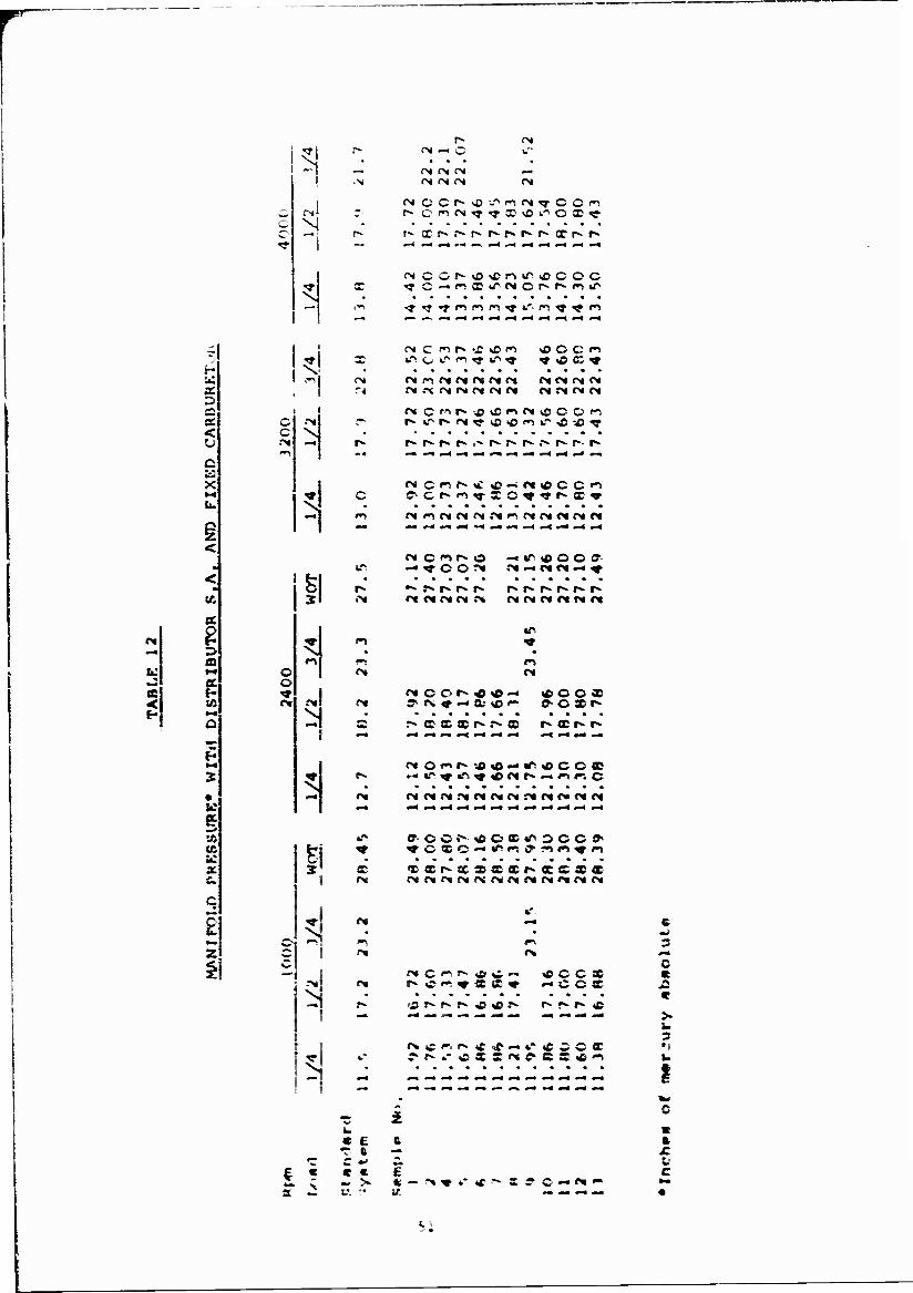
a < u c t: x
51
N
CX f* fN (N fN <N
(N
fN
h» Xr^r-f^r^r^f-t^xr-r*
"? tj-tM^n^f-n^^n
C fl h -f O « ICOCI <_. u" r-i *r *r ^ «isc«
fN !M («1 fn (>( M N N IMOItNN '* JM «X OJ CM O» <N tM JNMNN
<N C M f" * C " N lO O O ^
n* c »t r» »C »© —iNtf CC1^
m 1 M !M N .N ?" N N f« N N
<N
•J & <
<
as
♦
g V. « id a c c
i
o ©
II
sj
f* C <"» r"- O H^AOO?
<j
I!
ä -
On
••» r- r» r» r» m et m <M f*
r» r-» r» r* r- r>
IT
fM
: -
X
— P«
9 O O r*- <0 lO "* .•N. <* —• X <£ —
* o c *
f«*. X X X r* r» 5 p» CD r*- i^
O *"» P» «r» ^ tr>
■J> O — «■" C C C X
NNPIMPCMPI.^MMMPI
ffOO>- <r c « c OCX«." 300
?•» «n ^
TXP*XXXXr*XXSX
r»
I
^ =
p» c p»
X X * « C C X '«OCX
cS r^ r» r^ c «c p* r» ^ p» <£
.'S C ~- C X £ — *- c ^^ X
- - — - «~» - « *— •-• - -m -
c 3
c
u z
I
■ \
« £ e «r ft - c o E
* — -» * *- *r S 9 C «- <X »"
ft
c
l.

■: ■ gap —i
s
g iC
g C at
Q »5
w e <
■
as
« & =
\
15) I !
C
cj
o *T
5
<N
c
.C
c —
<M
r*
1 "■ £ C
^,
\ r* c ***. • c *T c M4
<M N. r- —
0*
X ■
i/- o r- c
r~ X X -i; 'y *? *? <y
O -" X fM — t •" ?M *? <N X ^
.NfS — IN — Mr>i!\fMrN(>( »w\ ?*K f** f*^ ^» f^ *^ •■»* ^\ ^_ *^i t*\
rx ,£ *~, r-* r^ r ~* "~ w* ~ >CC
ccscx.' <? » : T »• i *
w «** > -~ -■>• c - -~ «r ~ «?
X C w w C C w ~ w r^ c <y *? ■v «y « •<? ■"? ,?T'r'?
..- .* J ? f r •> > "\ i" p> S
^^l ^ ^^ ^^ ^^ *^ ^^ ^**. ^^ ^^ f^ «^
X «T tt •." «r '>s »^ — — *." o 91
«r «r if *n «r o *D *•" «•" ■ *r x «r
f» :■» o« c >•* *•" <N w C- x <"M
C C ~- O f* C ~ •-« »- O C *T iT »"> «." 4." i." |T «.*> tT «n «T<
—
—
V W~Nf c- O »C *"" W
C C -"" c c <£ *-~ X w X «C M MN N M ^ Oi OS Ot r* !>t
C *■"! «T ■ 0* C X X \5 <N 4.*" r*i ».'
IT Oi C f*. O -+ tT\ (H *F 9 «T f\
ccxccc'cc ? C c c-
r» — ^ r*» *r r» <*5 «IMNN
focc»1?: occo
4C «.'■ ^ <• »"V 4T ^ if \!\ «T <y _-
c 2
« e c «c « —
« r *« a E « « ■ E tc »3 v, ir. Ui — — _ _
E
« c u
c u c i. E v
u C
c i u c -: u c
r o *- t 9 V- u 0 U «
52

• I
! -! i i
N IT t?» N O l" | I I fM rx >~> *T *T *T *T *■" T 1 J I^^V
a IMMI I I i • I ry i Q i *r »T ^ t i i i it" i if
ft w
U
5 x s. < u
X
p 5
«T -
-3 S.
2
K < y.
x O
M X
N
•■%
\
fcl 3;
<r —* *— N. o «*> m 4
i
h
R
-"X
M
M
n i" *\ M IT n r> o i"» »•» »*»
i «■ r r- c c i i i i i«c i * *r ^ *■- *•" i i i i i *
«.~ O ^ «r» x X- *£ «rs «r - rf* .\ .>i M .•«i N o« f» f* r. x r»
n {*> >r •£ «X ^ ^ f •« »•4 «•» i»v i"i «•>/•> »»v /4\
1 .' "I* — «£ i.~ I I I ^ «Ml • * *• ^ * * . I • ♦ i *
x c «c x 4- x c- •** ^ x x c _rvi__ — —>.->i — — — — rs
C X C r^ <x ~ C rvc^* i» . r» n !>• <"s «^ "*. oicniy
X «.'"■ *C «0 * ifi *c r* X ^
WfNi • c e •c t —
•c C *J Cs. EC C ■ E •
r* X 0* O — ** *""
c & m* c c s •-• - c ;, ■ r c -*■ •
"C c
S! U JC
• « — ** * o W C •4
4. ft
4, -
* c «J «c £ C IT« ^ -• *
c 9 C
1 C —
u £-
** »- c C ^ ft fc
JZ * - ft • _; — «£ - 9
c «. r c « u
A ft » 4 V. w E ft c ft C a ft
> t •
V TJ C mi c ft 9
■*• 0 C X -- c
it » *- I ft X
J2 V m *•■
C *i ..
s s ft
c «-* f>« z
S3
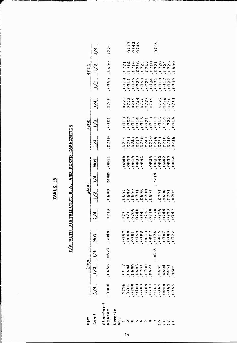
^anpasse .
r
51
s ^ <?
3
3
-I
i
N ill N
* h
c
c
c o
r» c
11! 5 a
i *i
N
i
r» (N i." *r — i? -r r^ r^ r^ r~ O W w O
r>. — ^- — n ^ « f\ r« (x ,->i s>
r — t-cc\t^^S!-r^c .« — r^ r\ »." f\ rs r- — »« r* —«
— f« r « c ? r r« -fie « f% ** — ^i \ *«-. M r>«f" r
«*> f» »*; ^ t* — c *•* »" ^ ^ i» — C — — — r* -• — — — Ot «—
«.««».» f^ a — p«ncc« »*^^»^ni^^ *■* ^ »^
CCCCCCCCCCCC
s ©• c «•» c «.' •■» c -^ r ^ «*." — »".• f<* f« ^ • .•— sssxe- e s s x c a ccccc ccccec
r* r\ r — S a — »-C— *■* rarerer c r c c ^ <C * :^ tf •" C r^tfr»r^ ^ Ä A — ,», «K »-« _._«._ w '- — ^ — W _ — . ^. «»
— — CC — — ^^C♦•--^* — — C » » »* —• — .r"1 ^ «.* ^
r- . «- •■« «^ •■■ ^- ^ **. A « ,» ^.
r» a — e ?<* »~ T~ «»*?»?-« rears — c?* — aa- r^ a ?*■?*• ?* ff 2 ?*• £; r* ?*■ T*
C .* w —
i*- ^ c *■' f c i* .* «e #*. «.- ■ a a a c c ^- r r c a fcCtftf^^C • C C ■£
c — c-'-r--cac4- rarsas^^accc J*. *». *». •*. #•» •». ** *•, **. g*^«fc.
C I t _ 7 • T
I * « « t • - ^ - > ft i — "*«»- c a. .- Et It tt 3
•■%

TA
BL
E
16
BS
FC
W
ITH
D
IST
RIB
UT
OR
S
.A.
AN
D
FIX
ED
C
AR
BU
RET
OR
Rpm
1
00
0
24
00
3
20
0
40
00
Lo
ad
1/4
1
/2
_Uj_
W
OT
__ l.
/'4
:V2
__
__ JL
4 __
W
OT
1/4
1
/2
3/4
1
/4
1/2
H
OT
Sta
nd
ard
S
yst
em
.98
5
.59
3
.53
0
.63
7
.79
5
.57
9
.5!2
<
56
2 .8
73
.6
14
.5
42
1
.00
0
. 71
9
. 62
4
Sam
ple
N
o.
l . 9
54
. .6
07
.5
94
.7
93
.5
66
.6
02
.8
70
.6
11
.5
61
1
.07
0
.69
6
2 .9
03
.5
74
.5
98
-?
66
. 5
62
.5
96
.8
75
.5
83
.5
43
.9
90
.6
80
.6
L:9
'
0y
4 .9
60
.5
82
.5
92
.7
75
.5
63
.5
78
.8
68
.E
08
.5
50
1
. 0
60
• 6
86
• 6
27
I
v,
5 .9
46
.5
83
.5
93
.7
61
.5
62
.5
94
. 8
53
.6
06
. 5
49
.9
74
.6
72
.6
10
6
.92
6
.61
8
.59
6
.76
8
. 56
5
.58
3
.87
4
.61
3
.55
5
1.0
80
.7
12
7
.95
4
.61
5
.61
4
.77
5
. 56
6
.85
5
.62
6
.55
4
1.1
10
.6
85
8
.95
2
.58
6
.60
4
.78
3
.56
0
• 57
8
.85
0
.61
4
.55
6
1.0
60
.7
06
9
.92
6
. 5
16
.5
82
.7
96
.5
21
.5
68
.8
71
.6
09
.9
59
.6
98
.6
14
1
0
.93
0
.59
2
.59
2
.67
8
. 56
8
.59
7
.87
2
.62
2
.55
5
1.1
50
.6
95
1
1
.96
3
.58
5
.57
4
.79
0
.56
8
.60
4
.89
0
.61
1
.55
7
1.1
90
.7
02
1
2
.97
8
.59
6
.59
9
.81
0
.57
1
.59
0
.87
6
.63
0
. 56
4
.98
2
.70
1
13
.9
36
.5
96
.5
86
.7
76
.5
70
• 5
79
. 8
65
.6
31
.5
68
1
.05
0
.71
0
•
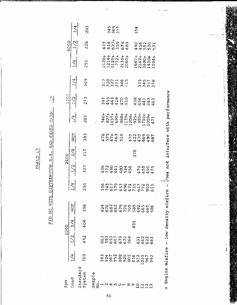
1! 'I
TA
i3L
S 1
7
FID
H
C ~HTH
DIS
TR
IBU
TO
R
S.A
. A
ND
F
IXE
D
C.C....~B: _
-:?
Rpm
1
00
0
24
00
32
CC
4
01
)0
Lo
ad
1/4
1
/2
3/4
W
OT
1/4
l/
2
3/4
H
OT
... /4
.
/~
3/4
l/
4
__
l/2
3/~
1.;
L --
Sta
nd
ard
S
yst
em
7
02
4
52
4
04
5
96
3
95
3
27
3
17
3
83
2
85
2
73
2
69
2
55
2
26
28
3
Sam
ple
N
o.
1 9
93
6
63
6
24
5
56
'
43
6
47
6
74
0+
3
97
3
17
2
12
0+
4
77
U
1 2
92
4
59
3
67
6
74
5
i 7
72
5
79
8
27
+
45
5
33
0
12
14
+
41
4
34
5
(j)
4 9
67
6
53
6
82
6
17
4
90
4
76
1
15
0f-
46
3
32
7
21
20
+
62
7+
36
13
5 9
52
6
07
. 6
62
5
79
4
41
4
69
6
90
+
42
8
33
1
77
2+
3
59
3
17
G
8
88
6
79
6
79
6
53
4
83
5
10
8
68
+
47
0
36
6
24
30
+
67
9
7 9
26
6
70
7
26
6
96
5
24
1
13
0+
5
10
~·l5
20
60
+
48
3
8 8
05
5
64
7
05
6
71
4
56
4
70
1
20
8+
9
85
6
43
5
58
5
73
5
32
6
42
2
92
5+
4
08
1
68
"i+
4
90
3
54
1
0
91
2
63
1
69
2
61
7
47
0
47
0
99
3+
4
56
3
35
2
14
7+
4
56
1
1
10
35
6
62
Ei
65
77
2
45
5
46
9
17
10
+
44
1
34
5
34
80
+
55
2
12
9
67
6
22
6
65
9
00
4
50
4
90
1
05
9+
4
63
3
'i7
14
30
+
53
0
13
9
93
6
43
5
86
6
15
4
75
6
87
6
71
4
62
3
78
1
59
4+
~31
I +
E
ng
ine m
isfi
re
-lo
w d
en
sit
y m
isfi
re
-~0es
no
t in
terf
ere
w
ith
perf
orm
an
ce

TABLE 18
:OLD START COMPARISON TEST
IGNITION SYSTEM STD. STD. STD. CD CD CD
Start No. 1 2 3 4 5 6
Ambient Temp.Cycle -26°F -25°F -25°F -25°F -26 °F -25°F
Battery Temperature -26°F -28°F -26°F -27 °F -27 >F -26 °F
Crankcase Temperature -29°F -28°F -28°t -28°F -28°F -27 °F
Soak Period (hrs) 20 18 18 16 19 18
Engine Started yes yes yes yes yes yes
Required KV-crank :i 8 11 15 10 13
Required KV-run 4-5 4-5 5 5 5 5
Available KV-crank(1) 18 J8 16 22 22 23
Available KV-run (1) 22 22 22 25 22 24
Battery 0/C Voles 24.2 24.5 24.8 25.0 25.0 24.4
Cranking Voltage range
10.8 22.4
20.6 22.4
20.0 22.4
20.8 22.6
20.8 22.4
20.4 22.4
Cranking Current (2) 30-20 75-20 84-24 82-22 80-24 78-24
Cranking RPM (3) 85 85 82 85 85 87
Start Crank Time (4) 4.6 6.6 6.6 6.1 6.5 9.4
Time to First Fire (4) 4.2 6.3 6.3 5.8 5.7 8.0
Notes: (1) Lead disconnected from spark plug. (2) Amperes (3) Average over first 3 seconds (4) Seconds
57

TABLE 19
DESIGN SPECIFICATIONS FOR DELIVERED SAMPLES
Input Voltage
Current Drain (@ 28V)
Output Voltage
Risetime
Ignition Coil Energy Source
Spark Energy
Spark Plugs
Engine Speed (max.)
Temperature Range
Recommended Tachometer
7 to 40 volts d.c.
.18A @500 rpm increasing linearly to
.70A (14000 rpm
15,000 volts minimum with a load of 150 picofarads and 100,000 ohm shunting resistance.
8 microseconds, 10% to 90% of maximum output voltage with 150 pf and 100 kilohm load.
1 uF charged to 360 volts.
8 millijoules measured at spark plugs on the engine.
Annular gap, 14 mm, 3/8" reach, Champion type MJ-V103.
4000 rpm (4 cylinder, 4 stroke cycle)
-65°F to 250CF2
Sun Electric, ST503 tachometer head and EB-4 or EB-14-A transmitter.
NOTES: (1) Basic design provides for other speeds or number of cylinders by changing converter transformer and switching transistor.
(2) System is designed for this range, but was only tested from 250°F to -25°F.
;-8

Unclassified Security Classification
DOCUMENT CONTROL DATA -R&D (Stcurliy clmtttllvtion of llllm, body of a6»irac( and Indanlnt annotation mult 6« anlarad whan lha cvtfili ttport It clattltladj
1 ORIGINATING * c r i v i T v f Corpora)« author)
The Prestoiite Company, Division of Eltra Corporation, Toledo, Ohio 43601
M. niPOKT SECURITY CL ASSIFIC ATION
Unclassified 26. GROUP
3 REPORT TITLE
MAINTENANCE FREE IGNITION SYSTEM FOR THE M151 VEHICLE
4. DESCRIPTIVE NOTES (Typ* of report and (ncfuafv. dafat)
Final report Sept.69 - Oct.70 ». »uTMOHUifr'/MiiuiM, oiiddfa Initial. Ian naitiij
Norman F. Sieja
«. REPORT OATE
Nov. 70 7a. TOTAL NO. OP PAGES
58 76. NO. OP REPS
Sa. CONTRACT OR GRANT MO.
DAAE07-70-C-0111. >i 6. PROJECT NO.
M. ORIGINATOR'S REPORT NUMBERIS)
11146
id. OTHER REPORT NOIS1 (Any other number« (hat may 6a aaatayxad tkli report;
TRIBU TION STATEMENT
Each transmittal of this document outside the agencies of the U.S. Government must have prior approval of U0S<, Army Tank- Automotive Command, AMSTA-BSL»
II. SUPPLEMENTARY NOTES
Contactless, solid state capacitor discharge ignition system.
12. SPONSORING MILITARY ACTIVITY
Vehicular Components and Materials Lab. U.S. Army Tank Automotive Command Warren, Michigan 48090
IS. ABSTRACT
^•Optimum ignition parameters are determined from dynamometer tests con- ducted on an Ml51 military engine equipped with a programmable capaci- tor discharge ignition system and compared to a standard military ignition system. A capacitive discharge ignition system is then designed to meet the selected ignition parameters with the purpose of producing an ignition system which is maintenance-free for the life of the vehicle. Vehicle life is defined as 50,000 miles or 3500 hours of engine operation. Data collected during testing are used to show the difference in performance of the two types of ignition systems. The effects of spark 2nergy, spark duration, voltage rise-time and peak power are discussed. Twelve sample ignition systems with optimized ignition characteristics are constructed, functionally tested and delivered to USATACOM for further life tests.
fRkfV PORM € A ™I*> ««PLACE» OO POMM I47S. I JAN «4. WHICH I* DD . NOV.. I 473 »••OL.T. PON ARMY U.E. Unclassified
Security Cl«..lflc«tlon