Embed Size (px)
Citation preview

UNCLASSIFIED
AD NUMBER
AD000587
NEW LIMITATION CHANGE
TOApproved for public release, distributionunlimited
FROMNo foreign distribution
AUTHORITY
ONR ltr., 9 Nov 1977
THIS PAGE IS UNCLASSIFIED

A A
It L Al I4ii rr

1MA0 ACHUSETTS INSTIUTE OF TECHNOL'OGY
Department of Aeronauticall E-ngineering
7rOTRACT NO- N5 oi- 07833
On~ !'XTC T n- c64 -259 2
MM~ODS OF DSTRMINING NATUR1AL MODMS AN~D MRq~UENCIBS MR
ThA1SVERE VIBR.ATIONS OF B7AXS
RMET 7011 TEM
OFFICE 07 NAVAL E.ZSMARCEUnder Contract No. N5 ori - 07833
by the
XASkSZCSTTS INSTITUTE OF TECENOLOGY
May 15, 1952
Raport by: _ _ _ _ _
f--1 Vward. A. Muellor
Approved. by:-
A AR OU- ELLASITI11C AANrD S*3T1RKUUCIT U R ES IR EL3ELAAR',CC

VIALASACHUSETTS INSTITUTE OF TECHNOLOGYDepartmnent of Aeronautical Engineering
CON'rrRAC" 140 N5 ori - 07833 PAGE iii
TABLE OF CONTENTS
PAG2
CHAPTER I - Introduction ................. I
CRA1ER 1I - Mathematical Prerequisites
1. Notations, Matrix Calculus ........ .................. 4
2. Series Zxpansions of Arbitrary' Functions ... ......... .. 11
CRAP=Th III - Transverse Vibrations of Straight Bars.
The Mechanical Problem
1. The Differential Equation of Vibration .......... ..... 18
2. Variational Methods
a. General Comments.................. 28
b. Formulation of the Zigen value Problem ..... ........ 30
c. The Ritz Procedure ............... .................. 341
d, The Choice of Coordinate Functions for the RitzProcedure ...................... . 37
3- Integral 'Equation Methods
a. Influence Coefficients...............0
'b. Influence Functions ........ ................. L1
c. Formulation of the Integral Equation .... ......... 45
d. Approximate 9olutions of the Integral Equation .. 1. 31
e. Approximate Solutions of the non-linear :ntegro-rifferential Equation ................. 59
f. On the Convergence of the Collocation Method .... 66
g. The >{1thod of Station Yunctions. ........... 68
4. Limitation cf thrx Analytical Methods .... . .... . ?2
AFR"O.PJIASTLW AND STRUCTURF_£ RESEARCH

MIASSACHUSETTS INMTT•TE"E OF TECHNOLOGYDepnartment of Aeronautical Engineering
CONTRACT NO. N5 or - 02833 PAGCE
METHODS OF DMTERMIN•IG NATURAL MODES AND FE~IM CIZS 01F
TPA1SVERSE VIBBATIONS OF B3ZAMS
CRAPTER I
LNTRODUCT I ON
Much effort has been spent in finding exact solutions of the
differential equations of vibration problems. In only the simplest of struc-
tures, viz, the uniform beam, is it possible to determine rigorous solutions
that include the effects of rotary inertia and shear resistance of the beam.
For beams whose cross section varies in a simple manner along the axis of the
beam it is possible, thouagh somewhat difficult to obtain exact solutions that
include the effects of rotary inertia. For arbitrary variation of the mass-
density distribution and arbitrarily changing elastic properties along the
axis, even if they are expressible in analytical form, it has not been found
possible to obtain exact solutions. Consequently the emphasis of this report
lies in obtaining approximate analytical methods rather than in working out
the solutions of the differential equations of a class of beams with, say,
cross sections that vary according to sirmle analytical functions along the
axis of the beam. The differential eq'ation of the problem will be developed
and it will be seen that it does not lend itself readily to the determination
g of approximate numerical solutiones It is =,ch more advantageous to set up
the problem in its integral equation representation, because integral ecpua-
tions can easily be solved by approxLate methods. The reason lies in the
entirely different approach that leads to the integral equations in contrast
with the differential equation zethods. The differential equation ;ccnsiders
AZRO.ELASTIC AND STRUCTURES RESEARCH

MASSACMUSE'IIYS !NSTiTUTE OF TECHNOLOGY
Department of Aeronautica-l Engineering
~PACE 2 CONTRACT NO. N15 on - 07833 1
Sthe elastic structure in its elements! it studies the motions of a particle
of the aggregate that makes up the structure and builds up - by Integration -
the motions of the stracture as a whole. These must be comnatible with the
conditions of support, and it is here that the real difficulty arii laborious-
ness of the differential equation procedure enters: the solution of the bounda=
ry-value problem, or the evaluation of the constants of Integration. The
integral equation considers the elastic body as a whole and it has, so to
speak, all the boundary conditions of the problem written into it. It is true,
that it builds up the motions of the body from "elements", but these are not
those of isolated particles but simple motions of the whole structure. The
integral eqpations are not the only ones that consider the body as a whole,
for the variational methods, better known to the engineer as energy methods,
also formulate the problem for the body as an entity, and it is convenient to
say that mechanical problems of vibrations can be stated in either differen-
tial form or in integral form. Here, attention is focused on the integral
formulat ions.
A few comments have to be made about the term "exact solution" that
has been mentioned above, i.e. it has to be stated ucnder what set of condi-
tions an analytical solution shall be called exact. The ecuations of the
problem shall be linear. This limits the magnitude of vibrations to so-called
small vibrations and. it requires linear stress-strain relationship. ParthSr-I ore the sL-plified beam theory shall be valid. This means that zhe Bernoulli-
Navier hwpothesis - plane sections which are normal to the undeformed elastic
axis remain plame and norral to the deformed elastic axis - is valid, and thýs
any exact solution is not rigorous in the sense of the mathematIcal theory of
S ARO-FLASTIC AND STRUCTURES RESEARCI-H

MASSACHUSETTS INSTITUTE OF TECHNOLOGYDepartment of Aeronautical Enneering
CONTRACT NO.N5 or - 07833 PAGE 3
elaaticity, as the wraiplag of the cross sections has been neglected. (SecChapter III also.)
The following section demonstrates a few mathematical principles
that will frequently be drawn upon in the ensuing analysis.
AI
SAERO.EI ASTIC AND) STRUCTURES RESEARCH

kAAS A CHUS E S INST1ITFUT'!_E OF TEC HNOO -0GYDepartment of Aeronautic-' -F rqeeiring
PAGUE 4 CONRj~ACT NOJTN5 oni 07833
MATHMýAT1C&L ?B&BX4JWI.SI
1. Notations, Matrix Calcul.s
Matrix calculus will be used extensively in the following sections.
Thus it is necessary to list the notations that are used in this paper. They
are in accord. with continental practice, offer the advantage of sinplicity and
economy of print, and are closely related with indicial notation.
In inzdicial notation - as it is used hereafter - the convention is
established that, if an index occurs more than once in a product, a snmmation
over the index is to be carried out over a number of integers ranging from one
to n, unless otherwise specified.
For example:
=~ ~ LZbZ a > &~t~~4
-- ,a,( ,,4 ... - 4A., ... + -,,Q,<~~~'¼ ~~ e,/Lj, /r) U
S(il
The ranges of the indices ,J, k,J1 shall be n1 , n2 , n3 , n 4 , respectively.
Matrices are designated by arabic capitaIs; vectors, that is,
matrices with either one row or one colun only, by lower case arabic letters.
Row-vectors have superscrints, column-vectors have subscripts. Bold face
letters (or unaerlined letters) shall be used where confusion of matrices
S wish their elements Is i ossible. The following are equlvaleat notations of
AE .RO-.LA , .,, A.aNv STenRUC-Ojl..-,- rn. .IED RCH

AMASSACHUSETTS INSTITUTE OF TECHNOLOGYDep•rtment of Aerona~ltical Engineering
CONTRACT NO. N5 ori - 07833 PAGE 5
an m-row ncoltumn matrix, or an m by n matrix:
Y 0L, ae: .. ,A, ,
Salso: 2r , r,, , (s, a (
Multiplication of a matrix by a scalar, - as multiplication of every element
of the matrix by the scalar;
x- A (3)
Addition and. subtraction of matrices, - as algebraic addition of corresponding
elements of the matrices. (Corresponding means situated at equal places,
havving the same address or coordinates)
A -I +C= D -(d-4) where d<~j a~j-h 6 *
(4)
Addition and subtraction are associative and. distributive but are, of course,
restricted to aggregates of matrices which have all the same number of rows
and the same nu.mber of columrs.
Multiplication of a vector ýy another vector - the familiar scalar prodauct
of vector algebra is written as;
_ARO-ELASTIC_ ANXD1? STRUCTURES R-SE-AIRCH

MASSACHUSETTS INSTITUTE OF T•ECHN•LOGYDepartment of Aeronautical Engineering
PAGE 6 CONTRACT NO, 'N5 orio7833
and with it, the ralti-olication of matrices by vectors and matrices are easily
defined. The I indicates transpositions of rows and columns. (The dyadic
product of vectors is not needed here.)
.ultiolication of a matrix by a column-ve - is a new column vector whose
i-th component is the scalar product of the i-th roa vector of the matrix with
the column vector:
A(Tjb/ •(6)
Multiplication of two matrices, - is a new matrix whose ij-th element (that
is, the i-th component of the J-th column vector) is defined as the scalar
product of the i-th row vector of the first factor-matrix into the J-th column
vector of the second factor-matrix. The two matrices must be compatible, i.e.
the number of the elements in the rows of the first matrix must be equal to
that of the elements in the columna of the second. Symbolically the product
is defined as;
I1- 1 Ua b "-: -I (b
*~ ~ L Kf,
The matrix product is associative, distributive but not, in general, coz2uta-
tive. The following relations are true;
o!~ a A (8 C))(A -t- ACT. +AB#A
9 AFPrn.F[_AAT~i AND S;TRIfCTIHRFA RF'SFARCH-

MASACHUSETITS INSTITUTE OF TECHNOLOGYDepaurtment of Aeronautical E-gineering
• CONTRACT NO. 15 ori - 07833 PACIE 7
Slica in of a matrix w:ith B eil•rc•v ul-ar•z n
ijapon&l matrices. The leading (or main) diagonal of a square matrix is the
Sline which contains the elements with tvo equal subscripts, (ail). It is
only defined for equaee matrices. A matrix whose elementg are all zero is
called the zero-matrix. If at least one of the elements of the leading diago-
nal of a square matrix does not vanish, while all others are zero, then it is
a dponal-matr~ix A diagonal matrix with elements all ecual to unity is
called jnit-matrix. A diagonal matrix with elements all equal to a scalar
is ealled a ecalar-matrix.
Th~e unit matriz,
ha5 the property, AE= EA==A . 9
The diagonal matrix, 0) 0 C "
can either premultiply or postmultiply a matrix A yielding LA and
respectively. Premultiplication by a diagonal matrix multiplies the rows of
the second factor -, poetmultiplication by a diagonal matrix multiplies the
rows of the first factor - by the corresponding diagonal element, viz.:
It~ 31 -d -~* Q, V (10) I'Repeated products of matrices with the same factor are written as
powers of that matrix. The zero-th power of a matnrx is defined to be the
uXnit matrix:
AERO-EIAST1C AND S[tJ.ICTUU RESEAR-ICH

MASSACHUSETT"S INSTITUTE OF TECHNOLOGYDepartrment of Aeronautical Engineering
PAGE 8 CONTRACT NO.N5 orl 07833
Operations on matrices that are frequently used are defined next.
TMasposition, - is an interchange of rows and columns and designated by a
prime K Thus The transpose of a product is equal to the product
of the transposed factors, in reversed order,
(AB8) e M A' (12)
f or, if C -- AB1 0, bý YCcj') +-henC I
I (c< '-(c (; Q b,. K . , = S'A'.The inverse (or reciprocal) of a matrix, - is defined as that matrix
whose premultiplication, or poetmultiplication, with A gives the unit
matrix E . viz.:
A=AA" E.
The theory of determinanrts shows that the ij-th element of the inverse matrix
is equal to
IA (14)
where c. f, ai is the cofacto of the element -;. , and det A - IAI -
determinant of the matrix A .
Yore details may be found In any toxt-book on linear algebra. An easy oxpoei=
tion is W. L, Fern-ar t s, Alebra, Claredon Press 1941, and a very clear and
m A rnr§r ri A c'ri-' & 2!rN e-ym'Tý i r ý.r re nr'- ,-.

VLASSACHUS=TT1S INSTITUTE OF TECHNOLOGYDepartment of Aeronautical Enqineering
ScoTrA.-CT NO. X5 ori - 07833 PAGE 9
more advanced treatise is R. Larm-ahl ts, M-atrizen, Springer 1950, (in German)
The inverse of a product is equaal to the produc'.. of the nzvorse of
of the factors in reversed order:
(A B)~'= A(5
for then-orly: ABAB) ABA AEANe AA~t E.-
Frequently multiple matrix products will be encooutered which
originate from multiple summations, and the problem of writing such sumnations
as matrix products arises. Thus a few typical matrix products will be written
in summation form. Only the iJ-th element is listed. The ranges of i and J
are one to a antl one to n, respectively.
1. E.M~le: the simple sutmmation s .j r - ~ I a2w 1>ý a Eo ' 6 sr z V4,
If the order of the indzices in the second factor were to be reversed this
summation would coincide with the definition of the matrix product AS .
As a aim-ultaneoue reversal of the indices and transposition leave the second
matrix ~unchan~ged, = lb,) , the following is true:
If the individual products ac,-Kfb, in the sumat ion I &- b 16)
are multiplied, or weighted, by factors, , that is, if the summation
" 5 ib•• -a/ 1e given, observe that the weighting factor (or numerical
intagration factor) carries the column index k of the factor cZaW This
means tnat every colu=n of the matrix A is maltiplied by a certain factor
A17rO-F1 AC71( ANn. TUCT U~rTES4 P!ZPAI)C

MASSACHUSZFTS INSTITUTE OF TECHNOLODGYDena_•t-nent n,• Aeronautical Engineering
PAGE lo CONTRACT NO.r5 or - 07833
c4. The second of the equations (10) on page 7 shows that such a matrix
is the product of a matrix A , postmultiplied by the diagonal matrix
Thus one obtains:
(tA&~):((,K4),) AD3'()
which is also equal to, A(BD)' ;i
2. E ýlmve: given the matrix 5 whose iJ-th element is defined by the double
sum: -= b, C• . The object is to write S as a matrix product.
If one sets p e, . a,,, , the problem is reduced to that of the first ex-
ample, for than, =j - b- C,,.1 z ,c 4
This is the i}-th element of the product PC , where P=AB , and, since the
matrix product is associative, there follows:
5 = (o-a-6, ,)-(a,,) (bA4)(c,,..,) =AB8C
If the two summations, over h and k, are weighted with two sets of
factors, say, V=fk) and /zMy) , a double sunnation of the following type
is obtained, -S ý'ýK CQ.• ný M , and it can (using the result of the pre-
vious example) be written as the iJ=th element of the matrix product listed
below:
S W(sB) ANBMC N, ( 0(F. h,
If tne order of the indices does not agree with the one lsted
Sabove, transpositions must be made. Not all sunmations can, of course, be
written as tvnicaal elments of matrix products: the indiceas of the factors
A rO-E-LZ11%'AStC AN41D S-T1RUCU IRESEAC

MASSACHUSETTS INSTIRTUTE OF TECHNOLOGYDepartment of Aeronautical Fnginee-ing
SCONTRACT NO, N5 ori - 07833 PAGE 11
must be such that they can be arranged so that the first index of a factor
is the same as the last index of the preceeding factor. The nu=ber of pcssi-
ble weighting factors is the same as the number of summations. So, for in-
stance, the quintuple sum: S,,,C - 0 f C e f M ,whereor- CK K r h rv e M U
mkt hl' omV Pn, qr are weighting factors, can be written as the ij-th ele-
ment of the matrix product: S - (Sj) - AMBNCC) DELF.
Summations, as they have been illustrated in the two examples, will be
encountered wheLh certain integrals are evaluated numerically.
2. Series gaons of Arbitrary ,Fanctione
Another concept of greatest importance and frequent application is
the problem of the series expansion of arbitrary functions. It will be re-
viewed briefly, in somewhat more general form than it is found in the usual
texts of methematical physics, such as H. & B.S. Jeffreys, Mathematical
Ph__sics, Cambridge University Press 1950, or R. Courant & Hilbert, Methodez
der mathematischAn Physik, Interscience, New York.
Formulation of the problem:
Given P. set of no•l-overlapping subintervals of the line, i.e.
intervals of the form: ai L- x d bi. In this are defined a piecewise contin-
uous function f(x) and a set of functions, designated by All the
Sfunctions are subject to the following restrictions:
() '_'ey must be Integrable square, i.ti. their squares must be integr-
able in the interval.
(2) All inner products of the functions must exist in the interval.
R~ecall that the o of two functions g(x) and h(x) overx
the interval a x. x b is defined as!
Arr CV :'i17 A c-r14' A ArrN c -n~t "rT 10VC nE7Qzr' D'(LI

MASSACHUS-TI'S INSTITUTE OF TECHiNOLOGYDepartnent of Aeronautical "_ e-ering
PAGE U CONTRACT NC. N5 ol - 07833
A
The in-er product of a function with itself is called the aorm of the function
arAl written as:"
!Rtroduce the following abbreviations:
(f, ") % the ,m -component of f in the r,,s.
It is desired to approximate f(x) by a linear sf.aeggte of the 'Is,
f ['X s 'Q cf, CX7 (19)
in such a way that the approximation is best in the least squared error sense,
i.e. that the integral over the square of the error is a minimum, viz.
Nt J('C-~d /I~-l~ff) Mi~nimnum- (20)
The problem consists now in determining the exanasi~n coefficients
a'Uin such a way that M(x) takes on its minium. value. This implies that all
the partial derivatives of M with respect to all a, must be zero:
<1/, for all/,o a, 1,2, ... n. (201)
This set of n linear non-homogeneous equations determines the av.
Carrying out the partiAl differentiation:
and noticing that ~ ,there follows.
A DCn ri A (YT'1C A MnT' cT'rn Tor'm tT-0 ryTc-0 L r',rlr~ A ~'1*~h LJ ,JTX-D

M-ASSACHUSE'TTS IINSTIT67E OF TECID"HNOLOGY
Dc-p~utment of Aeronautical Emgineel ing
1 CO:NTRýACT NO. N5 ori 07833 PACE 13
2 dx Cvancelling the factor -2 and perfoz'mingv-
the mnultiplication ir, the integ-rand., one obtains:
I. (P-0 ao is a constan~t faotor)
which can also be written more conveniently as an equality of inner products:
With the abbreviations (18) this equation can be written as:
c % S a(21)
where 16 is the matrix of the band. C an~d.a are the column vectors:
Equation (21) has tha solution: a(2-2)
The ij-th element of the laverse matrix is given by: (b ~C f. bi./\\BI'
By virtue of the imposed restrictions, C exists (i.e. is finite),
and thus a exists if,and. only if, f3- exists. This implies that the
determinant of the matrix must not v-anish, viz.
ýý* 0 , (23)
If one writes this in expanded form, and introduces the definition of bi,
oearrives at the Ifundamental equation, the so-Qalle~. jam ýian,:
~~ (23')
wh iihte functions must satisf'y, in order that the exumanson (19) is
A~~~~ Tf, I i1f Tr% C-T'!71/- ?,-rlC Tn ~r i A RCHL1

•/ASSACHUSETTS INSTITETE OF TECHNOLOGYDepa&_-ment of Aeronautical EWgineering
S PAGE 14 CONTRACT NO.N5 or 07833
The aon-vanishirg of the 'ramian implies that the £*unctions
are linearly independent, for, if this were not so, a relation
d= o (24)
with not all coefficients di zero would be true. To prove this, note that
from equation (24) &V of the c a can be expressed as a linear combination
of all others. After introducing this into the equation (231) one obtains
a determinant with a column that is a linear combination of the other columns.
But fuch a determinant is always zero, hence equation (24) cannot be satisfied.
Returning to the expansion problem, the approximation f(x) (eq. 19)
becomes with eq. (22)
Obviously M(x), as a definite integral with non-negative integrand,
is never less than zero. From this remark a generalized form of the Bessel
inequality and the Parseval ecuality can easily be derived.
M was given as:
Expanding aneL carrying out the integrations, with the abbreviations (18),
this becomes: iv7- 2a4o~) j r : }af -Q c., a,, a-A.
and. introducing aL, from (22) as C ,one obtains:
S 2 Y' -
[ AERO-ELASTiC AND STRUCUTURiE RLESARCH -

MASSACHUSEI-1-TS INSTITUTE OF TECHNOLOGY
Department of Aeronautical Engineering
CODNTRACT NO. X5 ori - 07833 PAGE 1
Since k I is the product of a matrix and its inverse and thus equal
to the unit matrix, one obtains fimna~ly
the generalized Bessel ine~qalityc tcAF (25) II
As the right-hand side of (25) is independent of the range of the summations
of L.- and A4 from one to n, the summations on the left-hand side can be ex-
tended from one to infinity.
Now, there always exists a number n>-NN such that the squared
error M is less than ar arbitrarily small 6 , i.e.
rL f- -< e& if n ) N.
In the limit n-4- M becomes zero and the Bessel inequality reduces to an
equality,
the generalized Parseval equality: bK C j, C . (26)
The equation (26) can also be called a generalized completeness relation.
An infinite set of lineraly independent functions is complete if it permits
the approximation in the mean (least squared error sense) of any piecewise
continuous function to any desired degree of accuracy.
"It should be noted that the equation:
A. jf- a, v< ,or l.i.rM. ( f aCu, -- 0 (27)
(1.i.m. means limit in the mean)
does not imply the equality:
SAFRO-ELASTIC AND STRUCTURES RESEAIRCH

MASSACHUSETTS INSTIT- UTE OF TECHNOLOGYDepartment of Ackronautical Engneerun
AGE 16 CONITIRACT NO. N5 ori -O0833
The latri rl assursad, ifthe sequence of the (0,92,j converges uniformly
in the subset of the line, because only then is it permissible to move the
integral sign past the summation sign.
Ve•ry important for later applications are the statements:
1 : A piecewise continuous fumction is uniquely determined by its ex-
pansion coefficients in a complete system of functions; or also,
Lemma 2: Two piecewise continuous functions are identical if they possess the
same expansion coefficients.
The proofs follow from the fact that the difference of two such
functions with the same expansion coefficients has an expansion with all
coefficients equal to zero. And thus, by virtue of the generalized Parseval
equality, its norm vanishes. But this implies that the difference itself is
zero, hence the two functions must be identical. The expansion coefficients
in a complete set describe a certain function uniquely, even if the series
expansion converges only in the mean and not in the usual sense.
It has been shown so far that any set of linearly independent
functions is a complete set. Among these the orthogonal (and normalized)
sets occupy a preferred position, because the determination of the expansion
coefficients of a function in an orthogonal system is greatly simplified, as
will be shown presently.
Two functions are said to be orthogonal if their inner product
vanishes, and they are normalized if their norm equals unity. Thus the set
(rl is orthogonal and normalized if it obeys the two equations:
orthogonality relation: Af = , f ,4t(29)
rnormalizing equation: / /or all w.. (30)
AFRO- VT ACT1C APir' TCD1 Te- DCC Orcr A DC!-

MASSACHUSETTS INSTITUTE OF TECHNOLOGYDepartment of Aeronautic. Lajineering
[ CONTRACT NO. N5 ero 07833 PAC, G 17
"The equat ions (29) and (30) can also be united as
in whiich c•e the set (I* is sail to be ortho-normal.
With equaation (31) the matrix becomes a unit matrix and thus
equation (22) reduces to:
C L (32)
which determines the expansion coefficients. They are the components of f
in the set of the Y's.
The Gramian (23 t) is now equal to unity, and thus, orthogonal and
normalized eets of functions are certainly linearly independent. (This re-
mains valid if the orthogonal set is not normalized, for the Gramian is then
equal to the product of the norms of the members of the set.) With B a
unit matrix B-I is also a unit matrix, and the double sums in the generalized
forms of the Bessel inequality and ParsevaI equality become simple sums over
the c's with equal subscripts:
Besse! inequality Ae 4/ ' (33)e efor orthogonal functions.
With equation (32) the appromimation £(x) is given by:
c~y~ (35)
which converges in the mean.
AER 0-ELA•,TiC AND STRUCTURES RESEARCH

MAIASSACHUSET1TS INSTITT OF TECHNOLOCGXYDepmp~ent of Aeronauticall Fngineeri.ng
FPAGE 18 CONTRACTI NO. N? oi- 07833?
g-EAF= II I
TRM.NV3E2 VIBIATIONY OF STMAIGET BALS.
TE3 U•0HINIC4L PROL Mý
1. Tbh Differential Eqation of Vibration (The Differential Alroach)
Let a bean with variable cross section be defined as follows;
x-x is a straight line and N is a plane normal to it. 01 is the intersection
of x-x with R. The boun&ary curve f1 (z) fl(yz 1 ;X) is subJect to _f1ve
restrictions:
(1) 0' is the centroid of the area encloeed by fl;
(2) Y, and z, are the centroidal principal axes of the area-
moment of inertia of the cross section;
A:n ' A4ZnC' ANMl qTDIrrTiIDrQ DCAI~L-J

MASSACHUSETTTS INST-ITUTE OF TE'-HNOLO-,,CYDepartnent of Aeronauticazrd ginee.ring
S CONTRACT NO. N5 ori - 07833 PAGE 19
(3) the y1 and za axes are always parallel to the y an. z axco
resnectivel-y;
(4). fi~x) is a functlio~n of x only and not of t~ime, i.e. the cross
:section does nuot chane its shape during vibration. (If the
crosa section is hollow, rigid stiffeners must be provided to
prevent change of shape.)
The fifth restriction will be formulated presently.
C"upposee that some forces p~x,t.) are acting on the beam in such a
way that thsyare in the x-y plane an normal to the x-axis. If the beam
was initially.at rest it will then vibrate in the x-y plane only when the
time dependent forces p are acting.
In order to study the motion of the beam, isolate a small slice
which is cut out 'by two negghborig normal planes R and V, apply the inner
forces between it and the remainder of the beam as, exterior forces and for-
mlate the equilibrium equations. These state that the a= total of all
forces and moments, including the inertia forces and moments, of course, must
vanish. Due to the simplifying assumptions, only two of the six equilibrium
equations (in Cartesian coordinates.) are not trivial, namely, that the sum
of thie vertical forces have a zero-resultant and that the s=m of the moments
about the z-axis have a ýzero resultant moment vector. 'The following figure
shows the isolated slice of length 4 x. The inner forces have been combined
into a shear force Q and a bending moment M. The indices 1 1 and &
refer to left and right. 1f the be~aste oscillation is in the x-y plane only,
then the i-•s'ltant of the ehear'-stress intensities olf the e.ross section must
be Parallel to the y--axis. It is known, however, that this requlirement can
AERO-E.LSTiC AND STRUCTURES RESEARCHi

MA&SAI " I I S INSTITU 7TE OF TECHINOLGGYDepartennt of Aeronautical £ngineering
PAGE 20 CONTRACT NO.X5 or - 07833
only then be fulfilled if the exterior force acts through the shear-center
of the cross section. As the forces D have been prescribed as passing through
the centroid of the cross-section, it is thus necessar7 to specify that the
shear center be in the xzy planeý It is also know-n that a&n axis of syvmmetry
of a cross section is a locus line of the shear center. Hence the restriction
which must be added is:
(5) the locus line of the shear centers of all cross sections
must be in the x-y plane, i.e. in the plane of action of
the exterior forces which is also the plane of vibration.
The cross section must vary gradually, otherwise the simple beam theory and
the theory of the shear center are no longer applicable.
(Detailed discussion of shear centers of solid cross aectiona can be found
in A. & L. Fdppl, DranK und. ZNang, vol. 2, paragrph 78, Oldenburg 1944,
Munich.) Some other dynamic restrictions will be discussed in latter sections.
M•e• MIe The figure shows the slice A x andthe resultants of the noraal - and
f/ shearing stresses on the left and.
right faces. The resultants of the
exterior and inertia forces are
designated by ,".X, and /'4.X
r C is the center of gravity of thei I•,5 i
slice.
Neglecting the dead weight whic4 is an effect of higher order, the sun of the
vertical forces must be zero;
ApiCVFi A&TICm AhJN TTDTTrT1ITPPV PFARrCP

MASSACHUSETTS INSTITUTE OF TECHNOLOGYDepartment of Aeronautical Enneering
CONTRACT NO. N5 ori - 07833 PAGE 21
v0
and the sum of the moments must be zero:
Dividing both equations by 4 x and letting 4 x approach zero, one obtains;
where the definitions:
Ai AX'c /ir e
have been introduced.
If only the free vibrations of the beam are of interest, the fore-
ing function p(x,t) is zero, and P and M become the dI'Alembert inertia forces
acting per unit length of beam axis.
Due to the postulated linearity of the problem it is permissible to
consider bending and shearing distortions separately. The total deflection of
the beam is designated by y(x,t), the deflection due to pure bending by a(x,t)
the deflection due to pure shear by A (x,t).
Thus y= ý tf ce -)
The following two differential equations e.rpress aý in teonn of the bendi-lng
moment M and bending stiffness El, and R in terms of the shear force Q and
the shear stiffness GAr. E is Young's modulus, G the shear modulus,
- • s/ 2 (v÷d), = Poisscns's ratio for lateral contraction, I = Iz the
moment of inertia of the cross section about the zI axis, Ar = A/k the reduced
cross section. The valse of the reduction factor k will be derived
AERO-E•F 5TIC' AND STRUCTURES RESEAIRCH

MASSACHUSE'FI'S INSTIT UTE OF TECHNOL-GYDep_,rtment of Aeronautical E•ngLnee.riig
SPAGE 22 CORTNPACT NO0.5 orl - 07833 i
later. 1
(2)
The inertia force due to the transverse motion of the beam is equal
to the negative -product of mass density per unit length of bean axis, IA4 ,
mu2.tiplied by the vertical acceleration A .P..- . Before writing down
the rotary acceleration term, which is equal to the negative product of the
mass moment of Inertia per unit length of beam axis (about the z1 -axis) times
the ang-ular acceleration, it should be noted that the bendUn distortion
2 rotates the beam slices. The shear deformation j3 merely causes adja-
cent slices to slide with respect to each other. (This is the simplified
concept of the Asimple" beam theoryl) For small deflections, the angle of
rotation is equal to the angle of the tangent to the beam axis, which is in
turn approximately equal to the slope a() . Consequently the rotary inertia
forces Der unit length of beam axis are given by H =-, (.p • as"de•7]
With these, the two equilibrium equations of the slice become:
- •, (a)
• " " /•4, •,,,'.' (,o•)a
With l '.-Iih = 0<- /( from (a)
G~~1-1 iI76 r0 ,(c)
Differentiate (c) with respect to x:
S-i''- >(,i~)' 9(I/'J[A,.,)'d , (T/A,) - o, (0)
Avo"an I ARTIC ANnC. TRIITT1RFP R1q.FVARrI-H

MASSACHUSETTS INSTIT1UTE OF TECHNOLOGiY
Department of Aeronautical Engeering
CONTRACT NO. N5 ori - 07833 PAGE 23
a&n Subatitute (b) into (d):
-(e)
E xpress M by y as follows:
IE
Elg+El WaAr)'ISI
S•) If (1IA.) 'a0 "'11-4/;
4,'ffeten ate w/ice w,11 respect to -
A( r
and4 introcluce (f) into (e):
+ /A(X7Ar)'Q " , x; iA,- /S C . (/)
Rearranging (g), integrating (b) and introducing it into (g), the following
I integ~o-4ifferential equation is obtained:
(E',"- - ( z)'+,AI.-,-,'<Ij/') +V-•l•,)f i -
Ij (3)Fro= (3) all of the simplified equations 2A1sted. in the literatu.re can easily
be obtainel, for instance:
DAERQ-oE•.-T.,.. AND ST!RUCT1U-,.R.ES IR..E51E,,,RC

MASSACHUSETTS INSTiTUTE OF ITECHNOLOýY
Deparrtent of Aeronautical Engineering
ý AGE 24 CONh•,TACT NCO25 ori - 07833
Fee transverse oscillations of a bean, n inertia effects;
but e distortion. The shear resistance is theL infinite, i.e.
Poisson's ratio p ý -1, G = a and equation (3) becomes:
A4 ~ (4)
This equatioa is listed in K. Hohenemser & W. Prager, Zýh_ ik der Stabwerk,
Springer, Berlin 1933.
Free oscillation of a Drismatic bar, inciudinL rotary inertia and she~az
effects. Setting El, , Ar constant and carrying out the differentiations
in (3), Yields:
This equation is listed in St. Timoshenko, Vibration Problems in ?n ineerg,
van Nostrand, New York, 1948; where it is integrated for some simple types of
bouadary conditions.
Assning harmonic motion:
AjLK (6)
and introducing (6) into the equation (3) yields the ordinary differential
equation for the eigenvalue problem. YX is the characteristic circular
frequency of the vibration. The equations (3), (4), and. (5) become respec-
tively:
This is the differential equatioLý of the natural mod, including rotary
inertia and shear terms.
ArRO-Ei__LqjC ANDf STRIICTURS IR1EEARCH

P ACHUSETTS INSTIUTE OF TECHNOLOGY
Department -of Aeronautical Engineering
W COC'TRACT NO. S5 ori - 07833 PAGE 25
This is the differential equation of the natural modes, neglecting shearIeffects, but with rotary inertia effects included.
ET Ic * q1' (1IIM4e/AI /,r6 - (5')
This, t the .differential equation of the iatural modes for a prismatic bar,
Including shear and rotary inertia terms.
Iquations (4') vad (53) have been aolved iL Hohenemaei-P-rager'a
and Tinoahenkos texts for the case of uniform beams withrectangular cross
section. They show that rotary inertia effects become great at higher fre-
quencies, becaus, then the nodal points are close together and the contribu-
tion of the angular accelerations is of the same order of magnitude as that
of the transverse accelerations. It seems possible to solve equation (41')
also for non-uniform beams, say, for an exponential variation rf the height
of the beam. The method of variation of parameters will give an analytical
solution for the equation under the assumption that X is known. The real
difficulty arises when the boundary conditions have to be satisfied in order
to obtain the characteristic equation for the eigenvalues. An an.lytical
solution of equation (3'), followed by the boundary value problem, appears
to be much too difficult ezid tedious to be attempted here. Purthermore,
beams encountered in engineering practico have elastic properties and mass
distributions that can not readily be expressed by exponential series ard
po'ecr series aad It is co-cluied that the differential equation approacL i1
- APR(YP1 AQT-rJ AN) qTRIIM1ILF9 RrSFARfl- -

AMAS'SCHUSMTrS 1NS1.JUTE OF TECHNOLOCY
Depu•t•nent of Aeronautical Engineer'ng
PAGE 26 CONTRACT NO.N5 ori - 07833
not the appropriate ine for the problem. The integral equation methods an2.
variational methods will yleld practical solutions. Before these are treated
the derivation of the formula of the reduction factor "kO in A, = A/k is
given.
The picture below shows the side - and front view of a slice
of the 'bea~m acted upon 'by sheariag forces (ý only. Let it be assumed. that all
longitudinal fibres undergo the same angular deformation, i.e. the cross sec-
tion does aot change its shape. Denote by d8 the shear deflection of an
element of length dx. One obtains an
- equpation for d, from the fact that the
I [ exterior work done by k dtring deformation
Il is equal to the strain-energy (interior
work) of the shearing stresses produced
by Q. Q undergoes a displacement d and
Increases slowly from zero to its final
value Q. Ths the potential energy of Q,
1- is equal to:
i~e~~8/ ~(a)
The stra-L energy of the shearing forces is given by:
TA =o~n -f teg0Tal (b)
The volume 4ýates-ral ý-'V]/ is equal to dxfr5da'A since dV is infinitely thin
and r does not chAnge over the distance dx . The shearing stress inten-
sity is given by:
AI:Pn-71 Aq-nd- ANnf QTYTTD-iL~ocVQ;ý5A~Ci.

MASSACHUSETTS 1NSTITUTE OF TE"CHNOLOGY
Department of Aeronautical Engineering
SCONTRACT NO. N5 or. - 07833 PAGE 27
where Sz is the static moment of the shaded area about the zI-axis.
Thus, one obtains:
(~alx1 / f-c'/V4 (/& (&7xb / d12<
and since Q. and I are constant for a given x (integration over y and z):
z4
Equating (a) and (c): Ae = A , there follows:
A
and solving for d&/ I
One now sets:
/~(A/l)f_(? 6ý)V2A
The factor k depends on the cross section only. With it the differential
shear deflection is given as:
which verifies the equation (2) on page 22.
Values of k for some frequent cross sections:
Rectangle: k = 6/5; solid circle: k = 10/9; thin-walled circle: k = 2.0.
For structural I beams one may take with sufficient accuracy the factor kI
IC Ind t e cross section of the web only: A/k an t'web * If one tak~es the
total area, k varies from 2.0 to 2.4 for very small and very large sections.
APFRn.FI A;T1C AND .R'rRIICTIJRF_. RFSKARCH

MASSACHUSETTS INST-11FLVE OF TECIFUNOLOGYDepartnent of Aeronautical Engineering
PAGE 28 CONTRACT NO. N5 on - 07833
2. Variational Methods. jnt lA ýroach
a) General Comment
In the first section of this chapter the eigenvalue problem has
been formulated, by means of a differential equation and a set of boundary
conditions. This diffet ential equation expresses an equilibrium equation
that must hold for any infinitesimal slice of the beam. But this is not the
only way of deriving the differential equations. One could have utilized,
more elegantly, Hpailton's principle. For the development of the energy
methods this principle of least action (as it is called) is the unaturaln
approach to the eigenvalue problem. A very short and neat development will be
given which is taken from G. Hamel, Thporetische Mechanik, Springer, Berlin
1949, and which does not presuppose a knowledge of Lan~zange's equations.
The derivation of the eigenvalue problem follows an article by R. J. M&hly,
Die geniAherto Berechmang von Eigenwerten elastischer Schwingungen anisotroper
KVrper, that appeared in vol. 24 of Zr.ebnisfe d er exakten Naturwijsenschaften,
Springer, Berlin 1951, wherein that author investigated the characteristic
frequencies of crystals.
The PEinoinle of Hwilton (of least action):
Let dm be an infinitesimal mass element of a system, w its vectorial
acceleration, &Z0 an exterior (impressed) force acting on it, and S a
virtual displacement of the particle. r is the radius vector describing
the position of the particle, V is its velocity which is equal to the rate
of change of 7, ý = l/d.t.
Then, % els principle states that the virtual work of the
E A 11C- A ND S TR I U R S R SE 1%

£AkSSACHUSEITTS INSTIUTE OF" TECHNOLOGY
Deoartment of Aronautical Engineering
t CONTRACT NO. N5 or l - 07833 PAGE 29
inertia foroes is equal to the virtual work, 9Ae, of the impressed farces or
From it one obtains Lag-angels central equation (as named by Heran) by Writing
dm wý in a different way, i.e.:
But if the virtual displacements are possible d Y = S&dP, and
•4¶ Z iwhich is equal to the variation of
the kinetic energy.: .T Thus there follows the central equation:
Introducing the central equation (b) into Lagrange's principle (a), one
obtains:r
An integration between ti and t 2 yields Hamilt•ons principle in its general
form:
(ST - 1re) '
If the impressed forces possess a potential, i.e. if iAe is a
total dlifferential SAe. V- SU, then Hamiltonl:s principle appears in a
convenient form. ýSince the S- process is independent of the time variation,
may be taken -outtside the Integral sign::
AERO-ELASTIC " ANDE STRU" CT ' U "".. R""ESENRU-R H

MASSACHUSETTS !NSTTITUTE OF TECHNOLOGYDepartment of Aeronautical Enggneeing
PAGE 3o CONTRACT NOX5 ori 07331
L ie the 7Ar-raagian function: L T ' U The: integral over L is called the
action, whence the name of the principle. The variation ,' can be pre-
scribed to be zero at ti and t 2 . Then one obtains the usual form of Hamilton's
p rinciple,tz
and one says that the integral W f L dt is stationary in the actual
motion of the system.
If the system is an elastic continuum which vibrates freely (un-
influenced by exterior forces) then the potential U is equal to the strain
energy of the body. Thus one must express the kinetic energ T and the strain
energy U in terms of the deformations (displacements) of the elastic system,
introduce these into Hamilton's principle, and thereby obtain an expression
which determines the displacements.
b) Formulation of the Ei genvalue Problem
The free vibrations of a body are defined as the simple periodic
oscillations which are not inifluenced by exterior forces. Thus, the deflec-
tion of the centroldýl axis, which is representative of the deflections of all
the particles of the bar (as has been postulated), can be expressed as:
Y(xt) =y(X) sin (Lt -V) sin (,,A4-), (4)
where y(x) was again divided into two parts, CY, (x) and ý3(x), which re-pre-
sent the bending deflection and shear deflection respectivelýy, viz.
GA. " (5)
AE.RO-LLASTIC AND STRUCTURES RESEARCH

ASSACH'!JSEITS iNSTITUT• OF TECHNOLOGYDepartment of Aeronautical Engineering
CONT1RACT NO. N5 ovi 07833 PAGE 31
The kinetic energy cf the beam is obtained. in the following way.
Consider a differential slice of the beam. Its length is dx. The mass-lensityl
per unit length of beam axis in ?= J(x), the mass moment of inertia of the
beam about the 7i-axis ýsee figure on page 18) per unit length of beam axis
is given by '= '•(z). The translatory kinetic energy of the slice is equal
to 'Lx/2; and the rotary kinetic energy is equal to %dx/2. ( i !s
given by . T L.). Thus the total kinetic energy of the beam is expressible
as:
(6)
The strain energy, in term8 of bending moment M and shear force Q,
is given as U(j S-zdEI # d2 GA . With equation (5) this can
be rewritten in terms of the deflections as follows:
S= -• EI(o("), t-. ,•'2a (7)
The expressions for kinetic and strain-energy can be put into a form that
shows better that they are quAdratic forms in the displacements, viz.:
V[ tL " a It t LR 3 ýa
where the letters V and R are used to iesignate the kinetic energy due to
vertical and rotary motion, and the letters B and S designate the strain-
energy due to bending and shear. Furthermore the rotation is similar to that
used for the inner product of two functions (see page 12). Comparing (8)
and (9) with (6) and (7) one finds tbe definitions:
AERO-ELASTIC AND STRUCTURES RESEARCH !

MASSACHUSEEq1S INSTTUTE OF TECHNiOLOGYC.
Department of Aeronautical •n•ineering
IPAGE 32 CONTRACT NO.1N5 o- 078O33
1(12)
where )Z()
Hmilton's principle states that the variation of W must vani•h for
ay time interal t2 - tl* If one chooses this interval to be an integer
multiple of oscillation periods, then the integrals over co8 2 (4Wt +_r) and
su2( t + V) are equal, and one is left with the variational equyation:
9 ,B[(."-, " --S '~IIt/ ) - ýk(Vc~~ [ý )+REP /I 0 . (14)
This problem is equivalent to that of finding the extrema of the
so-called Rayleigh coefficient K(y) which is defined as:
K (ý =- * S(15)
and these are, by virtue of (13), identical with the characteristic values
i i2. For, if one sets out to find the extrema of a quotient. (u/v) and
designates any such extremnm by (u/v)extr", one knows that the variation
of (u/v) must be zero at every extremum, i.e.
S(u/V) = 0;
and carrying out the variation, one obtains:
(LA-/Lr) (Lr & LL V u
Since v # 0,
( .o ,,-
Thus SCLL-1-1)= is equivalent to f2nding the extroa of K(Y).
AEOELAST.C AND S NLJ.IUCT~ RM J'fl~-

M.A-SSACHUSETrS INSTITUTE OF TECHNOLOGYD epartnent of Aeronautilcal Engineering
ICONTRACT NG.N15 ori 07833 AG 3
There exist two methods by which the quotient K(y) can be minimized:
(i) One makes K depena on a series of arbitrary parameters &., a,
. .ar, and determines these parameters in such a way that the
function K(y; al. .an) is a minirram. :his leads to the re-
quiremernt that n equations:
--- - O (16)
be satisfied. The equations (16) are a necessary but not
sufficient requirement for the existence of a minimum, and it
can be demonstrated that they give an upper bound for the high-
er eigenvalues. (See for instance L. Collatz, Eigenwertproblem,
2. edition, pg. 274 etc.) This method is usually associated
with the name of RITZ.
(ii) One tries to make the coefficients of the higher eigen-fre-
quencie_ (c 2 9 c3 .... ) small with respect to that of the funda-
mental frequency c1. This leads to the method of successive
approximations (Iteration). After having found the first
eigenfrequency one will eliminate its component from the
Ray•ieigh coefficient and then again try to make cjo .1.
small in comparison to c2. Thus one obtains in succession the
first, -econd,.... modes. The great disadvantage of this pro-
cedure is the fact that it is very cumbersome to '1sweepm (or
to free) the Rayleigh coefficient of the components of the
modes that have already been iterated. As the nuecrical labor
increases rapidly for the higher modes successive iteration
=ethod.s will not be treated here.
AFRO-ELASTIC AND STRUCTURES RESEARCH

MAtSSACHUSEYVS INSTITUTE OF TECHNOLOGY
Depnartment of Aeronautical Engneering
PAGE 34 CONTRACT NO.N5 on - 07833
c) The Ritz Proce&ure
Let y(K) c<(x)t 3(x) be expressed in the form of a series
2;"" n
with Yj(x) =+ XL (%) +
ThA functions yi(X) have to be linearly independent and they must
satisfy the conditions of constraint (boundary conditions). Then B,S,V,R
become positive definite quadratic forms in the coefficients ai, (see also jCollatz, Eigenwertiorobleme) and are given by:
V8y'l R-a'o-]-ro.]a.a- ; with V% (B8)
,, S[a,a] sj, th aS.
From (10) it is obvious what vj, ] means: it is the value
of the following definite integral (to be extended over the beam),
The matrices (viJ),(rni) (bij),i(iJ) are all symmetric. Thus the
characteristic values are all real. The Rayleigh coefficient K( , is an
extremum if the equations: MK/ = are satisfied, or multiplying both
sides with (V -t R), one obtains the more convenient form:
S AERO-ELASTIC AND STRUCTURES RESEARCH

MASSAC..USETTS INSTITUTE OF TECHNOLOGYDcparinent of Aeronautical Eng-inee-'ng
CONTRACT NO. N5 ori - 07833 PAGE35
=VR3 b{BS~(1R jj
5ýý (19)
For, if one calls B S = D and V -- R = H, one has K = D/H which is the
furction whose extrema have to be determined, and it is a function of the
a Is,
The system of linear homogeneous equations (19) can have a non-
trivial solution only i the determinant of the coefficient matrix is zero.
This gives the so-called secular eguation (frequency equation):
det [ uij ti] 0
I (20)where uij = (b -s)ij and tij - (v + r)- j
It should be observed that the coefficients of RITZ's determinant
(20) can be obtained directlZ from the coordinate functions Yi(x), as is
evident from equation (18), and it is not necessary to carry out the differen-
tiations with respect to the ai's. As the matrices (ujj) and (tjj) are sym-
metric and (tij) is positive definite, all roots are real and they can
'be ordered according to size:
ý':!- , .! 'Z ý6 . . . ý ý .I
By a known theorem of algebra, the ratios between the coefficients
a., that belong to a Ritz value •r are equal to the ratios of the cofactors
of ary row or column of ui - tjj
.,.-.-•,--.•-,EAS . A ND UT RUCT R, ., J . .SE

MASSACHUSETITS INSTITUTE OF TECHNOLOGY
Department of Aeronautical Engineerirtg
PACGE 36 CONTRACT NOC.5 or - 07833
The corresponding solution functions Y r(z) (or approximations to
the natural mode shapes, as they are usually called) are given by;
Yr (x) ai yi(j) (21)
The determination of the ari is equivalent to the simultaneous transformation
of the matrices (ulj) and (tij) into diagonal form.
The following lemma is added without proof. (It can be verified in
a way siilar to that used by H. J. Mahly in vol. 24 of Eebaieze der z-k'ten
Natlurw is s ensc _aft en).
TIhe Ritz values ýj are greater than the corresponding exact eigen-
values \ but they are not greater than the next higher eigenvalue i÷
If one adds another function y+ 1 to the Ritz expansion, which is linearly
independent of all yl ... ,yn' then the Ritz values P of this augmented
system can only be smaller than the corresponding_ ones of the initial system
2.. but they cannot be less than he next lower value ) of the initial
system. I .
It Is also possible to prove here that the characteristic vibrations
are no longer orthogonal, i.e. that the inner product of ani two different
ones, multiplied by the sqcuare root of the mss density distribution function,
does not vanish an:-- more. This proof will be given in the next section, how-
ever, where it will be less abstract. The reader can find criterla for the
convergenc, -f the procedure in the paper by H. J. Miihly which has already
been ....
SAERO-ELASTIC AND STRUCTURES RESEARCH
PA._SACH US• E `! f• INSTITLrTE OF TECHNOLOGYDepaxrtment of Aeronautical Engineering
CONTRACT NW. N5 ori - 07833 PAGE 37
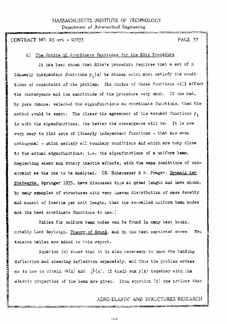
d) h Coordinate ?unctions for the Ritz Procedure
It has been shown that Ritzts nroceduro requires that a set of n
linearly independezt functions y'%;(x) be chosen which nast satisfy the conai-
tio~ne of constraint of the problem. The choice of these functions will affect
the convergence and the exctitude of the procedure very much. If one had,
by pure chance, selected the eigenfunctions as, coordinate functions, then the
method would be exact. The closer the agreement of' the assumed functions Yj
is with the eigenfurctlions, the better the convergence will be. It is now
very easy to find, sets of linearly independent functions - that aSe even
orthogonal - which satisf~y all boundary conditions and which are very close
to the actual eigenfunctions, i.e. the eigenfunctiona of a uniform beam,
neglecting shear and rotary inertia effects, with the same conditions of con-
straint as the one to be analyzed. (K. Hohenemser & W. Prager:, 2Xgimik der
Stabwerke, Springer 1933, have discussed this at great length and have showm,
by m e==ples of structures with very uneven disnribution of' mass density
and moment, of inertia per unit length, that the so-called. uniform beam modes
are the best coordinate functions to use.)
Tables for uniform beam modes can be found in many text books,
notablv Lord Raylei-h. Theory of Sound. and. Ln the text mentionad abnva. V-
tenBsive tables are added. to this report.
Equation (4) shows that it is also necersaz7 to kmow the bending
deflection and shearing deflection separately, and thus the problem arises
as to how to obtain 'V(x) and. ý3 (,x), if their sum y(x) together with the
elastic properties o~f the beam are given. From equation (5) one notices that
A~~OELSTCAND STUTRSRSAC

MLASSACHUSETTS MITSTIUTEE OFTEC•-1NOOGV•
Department of Aeronautical Engineering
PAGE 38 CONTRACT NO. W5 orl - 07833
both M and Q have to be obtained, in order that C:/ and can be obtained
by iategrations. In terms of a loading intensity p(x) per unit length of boam
axis, q and M are given as first and second integrals of p:
~. -S ~ M ~~ -f'~7 (2,2)
Differentiating (4) twice with respect to x, together with (5) and (22). one
obtains the folloving general relation between deflection y(x) and load inten-
sity p(m):
jY N) %1~6 A,.) f P'dx (23)
which reduces, for prismatic bars, to
! --- (M~>+ 2(t+1)-L P j rSSPd (23')d1 ErLA GAr
(See for instance S. Timoshenko, Strength of Materials, vol. 1, pgo 171)
The solution of (23) for p(x) with a given y(x) would be a very
cumbersome undertaking and could, in general, not be carried out analytically.
But remembering that the Rit2 procedure requires only functions that satisfy
the boundary conditions, and that the uniform beam modes are utilized because
they insure rapid convergence, one can modify the problem slightly and obtain
ci0. (x) and (3 (x) by the two following procedures:
(i) Take the mode-loads of the uniform beam. These are the static
loads that produce the mode deflections. From these one
obtains the bending deflection Cý and shear deflectlon "3
(The first eight mode-loads for uniform beams with various
boundary conditions are tabulated -I this report.
! AERO-ELAST!.C AND STRUCTURES RESEARCH

MASSACHUSETTS INSTITMTE OF TECHNOLOGY
Department oi Aeronautical Engineering
CONTRACT No. 95 or' - 07833 PAC.E 39~
~t)If uniform~ be= modle-load~s aro riot available, estimate the
lonation of the nodal points an. app•_y alte-nate uniform loads
between these nodes. Then, calcalate the bonding - and ahear-
ing deflections under these loads and use them in the Ritz
exnana ion.
The following picture illustrates how the third of the linearly
independent functions, Y3 (X) 0O3(X) -t •(x) can be obta~tned.
(The load-intensities pVP 2 ,P 3 can be equal, or can be determined such that
the points N. and N 3 do not undergo any static deflection.)
The underlying idea of this procedure is that these deflection lines
will roughly represent the natural modes and thus one is assured that the RITZ
values i are close to the actual A i and that the procedure convergesvalues
rapidly. The expansion coefficients (or 2Etiaipation feactors) of the r-th
linearly independent function yr(m) in the r-th natural mode:
Tr(x) = ar Yi (X)
will then be such that the factor arr is much larger than the other a rj3
(where J kA r). This means that the matrix (aij) is almost a diagonal matrix.
It is, however, not necessary to choose the n linearly independent functions
in this way, and one could, for instan.ce, also select the deflection lines
_ARO FiAST1( AND -TSTRC ES RFSARCH

MASSACHUSETT S INSTITUTE OF TECHANOLOGYDepartment of Aeronautical Engineering
PAGE 4 CONT-ACT NO. i;5 ori - 07833
due to a point load that is stationed successively in n different points.
(It is interesting to know that the :-th natural frequency of vibrating beams
is completely characterized by the location of the nodal points. In beams with
tboth ends supported one must not count one of these. The proof is given by
K. Hohenemser & W. Prager in ZAM't 1931, vol. 11, #2) jThe RITZ procedure offers the advantage that it provides the analyst
with relatively godo approximations to the frequencies and the mode shapes. It
has the disadvantage that the error in the approximation cannot be estimated,
and also that, if one adds another function yn + 1 to the set of linearly in-
dependent function {Ynl ' all the labor of solving the frequency equation (20)
has to be repeated. It has been mentioned that this addition of another coordi
nate function can only improve the results.
3. Itegral Equation Methods
a) Influence Coefficients
Consider a beam as defined in section 1 of this chapter. If this
beam is acted upon by a concentrated load P which is perpendicular to the beam
axis and located at a point designated by "Ji, then it produces at a point ij"
a deflection 8ij and an angular rotation 0 lj. Similarly, a couple at "J"
causes a deflection anij and an angular rotation qij at "i". The concen-
trated load and the couple shall both have the magnitude one.
Formulas for these influence coefficients can easily be derived
from the equations of virtual work. Let %. Qk (and M1k, k) be the bending
moment and shear force in the beam due to a unit force (and a unit couple) at
"k". Then the above listed influence coefficients are given by the following
integrals to be extended over the beam:
AFRO-ELAST!IC AND STRUCTURES RESEARCH

MASSACHUSET'S INSPITUTE OF TECHNOLOGYDepartment of AeronautieJ LEngineering
CONTRACT NO. N5 ori - 07833 PAGE 41
+
/E 1) x+ 16(A,
They obey Maxwell' s reciprocal laws:
as is evident from (1). If the point tiO has the coordinate xi x and UP
t&e coordinate xi C ý , and if both x and • are considered to be inde-
pendent variables, then the four influence coefficients become influence
functions.
b) Influence Functions (Gzeen.s, Functions)
Let the influence function corresponding to the coefficient •j be
designated by g. It is clearly a function of x and ý , g . g(x; ), and in
view of Maxwell's law it is symmetric in the variables, hence:
g~; ) =g(i ; X)
The determination of g(x; J) is sufficient, for, the remaining influence
functions can be obtained by partial differentiations.
aaI. The influence faction of angular rotation due to a point load is
equal to the partial derivative of g(x; ') with respect to x.
SAERO-ELASTiC AND STRUCTURES RESEARC ii

A-SSACHUS.U IS INSTITU7TE OF TECIHNOLOCY
Department of Aeronautical TnEginering
?AGE 42 CONTI, ACT NO,. 35 ori - 07833
The following aketch illustra-es this.
In order to obtain the defj.ecti'n in-
-- !P= 1 fluence due to a unit moment, obsexve
: I that a unit moment can be considered
"_ 7 as the limiting case of a ,couple,
Sg•x;~) - , which is subjected to the
/ ~x restriction: ,IMi, (Pa) =
The deflection at x due to a load P at
Sis giv~en'by g(x; .6~ P,
•---- 4a¶P and thus the d eflection at x due to the
couple P a is equal to P{g(x, +
- g (x; q - With P this
takes the form: %Wt{( .+U-g(:i,)} •
In the limit L6-•O the deflection at
x due to a moment h at
•21 (x(,
consequently:
Lemma 2: The deflection influence function due to a unit moment at • is
equal to the partial derivative with reppect to • of the defleo-
tion influence function for a unit force at .
Lemak 3: The influenoe function for the angrular deflection due: to a Uzit
moment, is equal to the partial derivative with respect to X and
S AERO-ELASTIC AND STRUCTURES RESEARCH
MASSACHUSEETTS iNSTEFUTEE OF TrECHNOLO0GY
Department of Aeronauticall Eng4 - ing
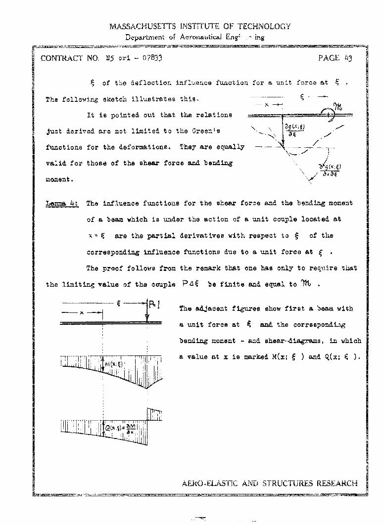
CONTRACT NO. 215 ori - 07833 PAGE 43
Sof th~e deflection in-fluence function for a unit Iforce at
The following sketch illustrates this.___
It is pointed out that the relations
just icri7ed are not limited to the Green's \'-.-\
functions for the &eformations. They are equally _ /
valid for those of the shear force and bending
moment. ' a
Lemma 4: The influence functions for the shear force and the bending moment
of a beam which is under the action of a unit couple located at
x g are the partial derivatives with respect to ý of the
corresponding influence functions due to a unit force at f .
The proof follows from the remark that one has only to require tuhat
the limiting value of the couple P b• be finite and equal to Th
-- l The adjacent figures show first a beam with
a unit force at 4 and the correspondiag
bending moment - and sheard!iagrams, In which
,i i" ,"FF7 a value at x is marked M(z; and Q(z;
SI , i I.
pIAE-RO-ELASTIC AND STRUCTURES5 RESEARCH
~ __________ - rv~. - -. - *~*

MSSACHUSMTTS INSTTITTE OF TECHNOLOGYDepart-tenit of Aeronautik.al E~nineermng
SPAGE 44 CONTRACT NO. N5 ori 07833
"Ne7t is the tame beam with a un it couple at
anud with the corresponding dilgruams for
Sthe boening moment band the shear force
_ _ _ _ [ote that the shear force is always the
';. ;. Ix-derivative of the banding moment, it isM(I XHt
I eths onl necessary to obtain the Green's
function of the bending moment due to a unit
force. The others are then partial deriva-
I i __ tives of it.
I HI[L'! , Sometimes the evaluation of the Green's
function due to a unit couple is easier than
the calculation of the Green's futetion due
to a unit force, followed by partial differ-
entiatione. Then one will, of course, d-e-
termine it directly.
Formulas for the Greents functions of uniform bewm are compile& in R. •oark,Formulas for Stress Eand $train, McGraw sill, New York 1943. The following
example was taken from this book.
Illustration: uniform bea=, simply supported, acted upon
-by a unit force, andr also by a unit couple.
M,,y . x The Green's functions, in the interval from
zero to • , are given by:
SAERO--IASTIC AND STRUCTURES RESEARCH

MASSACHUJSETrS INS;TMIMT OF TF.'NOLDGYDepa.rt-nent of AeronaubczI Engineeiing
CONTRACT NO. N5 ori - 07833 PAGE 45
One verifies here readily that the quantities indicated by a bar are the
derivatives of those without a bar.
c) Fox-_MLO~tion _Of .the Inteall Equation
Suppose that the beam oscillates freely. As shown in section 1,
every slice located at x a j is acted upon by inertia loadings which are
composed of the inertia force -FLAdf due to the transverse acceleration
Sand ths inertia moment - due to the rotary acceleration cC .
Let the deflection influence function due to a unit load at ý be g(x; • )
as has just been established in section b). Then the load at d
produces at x a differential deflection: -3(,9)t .
The deflection influence function g(x; ý ) is made up of two parts,
the deflection due to bending distortion only; c4 (x; ) and the deflection
due to shearing distortion only: (x; • ). Tms,
9%;f)= 0C(x (f3(:K;
According to Lemma 42 of the previous section; the deflection at
x due to a unit moment at 9 is equal to: ?3(-; )/a , and consequently,
the inertia moment -Z.'dg at 9 produces a differential deflection:
- _ d" at x. The sum of these two differential effects is equal to:*
AERO-F..ASTMC AND STRUCTUIRFS R.ESEARCH-

MASSACHUSETTS LNSTFUT OF TECHNOUCLOGYDepasriment of Aeronautical gine~efing
FPAGE 46 CONTIACTJ NO.5 or - 07833
One obtains the total deflection y(x) integrating over all the diffeientiatl
effects:
b
at
The natural modes are the free harmonic vibrations of the beam:
) (1)sia(wt+V) and, with W1 one arrives at the integral equa-
tion for the natural modes of the beam:
y+x aq TM* (2)
Equation (2) is a homogeneous, non-linear integro-differential equation of the
Fredholm type. The function Cv (x) &epends, as has been shown, in a compli-
cated way on Y(Z).
The equation can be simplified considerably if one sets: y(Xll
i.e. if one neglects the shear effects in the rotary inertia terms. This is
Justifiable, since for small vibrations and lower modes the function.s y(x)
and M(x) differ only very little and their respective first derivatives are
practically alike. Furthermore the approximation occurs in a term which is
only a correction term and much smaller than the first e~xpiesaion in the inte-
grand which represents the deflection due to transverse motion of the beam
only. (This question will be discussead in more detail in chapter IV.) With
AERO-ELASTIC AND STRUCTURES RESEARCH

MASSACHUSETTS iNNTITUTE OF TECHNOLOGYDepatrtment of Aeronautical Enginee._nmg
CON•TIRACT NO. L5 orl - 07833 PAGE 47
the slfpDliCmtion jL/'dxz dy/dx , equation (2) appears as
One can eliminate the derivative dyl/d in the integran by partiali
gration of the second term on the right and obtains then:
or also:;
Introduce the abbrevia.tions:
-b (4)
and recall the notation of the inner product of two functions, ther. (31) can
be written In the compact form:
gjo
Note w'ell that G is a function of x and a Green's function which is
.;ot symmetric, and y is a function of also, If it is in a round. bracket.
This bracket is a short notation for the definitf integral of the product of
the factors Inside, and, since G is also a function of x, which is not a-ffect-
ed by the Integration process, (G,y) must be a function of x. Similarly H
is a function of x and 9 , an y is again a function of E- , whenever It
is multiplied with another function. The vertical bar im-dicates that the
dif~ference of the values of the function ERy for b, and =a Is
CAWN CTDrT1 I'¢ RESEARCH

MAS.ACHUSET-TS INSTITUTE OF TECHNOLbGY
Devtm'eni of Aeronauticz1 Engin" ring
PAGE 48 CONTRACT NO. X5 ort - 078335
to be taken. Sttce x is not involved in this process of sTbtracting the lower
limit from the upper one, HyI is indeed a function of x. Consequentiy,
both sides of equAtion (5) are functions of x alone. If the simplification
o re~y is not made, equation (5) reads.
y(X) J'ý 9(.f C fa j=
From equation (5) one proves now without difficmilty that the charac-
teristic functions are not orthogonal, for, let yi and yj be two eigenfunctions
and Ai and ' tAhe corresponding eigenvalues, then the two following equa-
tions must be satisfied:
S= (+,-yz) +
(~y,)+ Hydj
Take now the inner product of the first equation with respect to y , also
the inner product of the second one with respect to yi, subtract the second
one from the first one, and note that (yi,Yj) = (Vi,7i) then one obtains:
-A-Lj -,A((Gy;))yj) + (Hyj),yy) - (r~y~),j) - (syj.y~)
If one writes this out in detail, it becomes:
-
bb
+ bt•fj( ,xd - Ixfy()3t•d
Inverting the dummy variables ±n the second term, and combining then these
- o~E-LA.STIC- AND STRUCCTURES RES•.•RCH

MASSACHUSETTS INSTITUTE OF TECHNOLOGY
Department of Aeronautical Enigineeving
CONTRACT NO.F5 orl 07833 PAGE 49
two intograle by factoring out yi( 9)yj(x), one gets:
bb
i =a
If the beam were supported at both ends, then y would be zero at the ends and
consequently the second integral of the right hand side of (6) would vanish.
Since G(x; g ) * G( 4 ;z), one concludes that for th'• case the orthogonality
cannot exist. If the beam is clamped at one end, then the second integral of
the right band side of (6) will not vanish, and, in general, orthogonality
cannot exist. In a similar way one verifies from (5') that the eigenfunctions
are not orthogonal.
Only if rotary inertia effects are neglected, can one obtain ortho-
gonality with respect to a weighting function /iAI) for in this oase,
equation (2) reduces to:
b
Y 3 (7)
W ith the new function ý F • y this becomies:
and if yi, Yj and ) , are two differnt eigenfunctions and their
corresponding eigenralues of the problem, there follows:
AERO.EIASTIC AND STRUCTURES RESEARCH

MASSACHUSETTS INSTITUTL OF TECFNOLOGY
Deporbnent of Aeronauvici ca ierin
SPAGE 50 CIONR'Arc NO.195 ori 078~33
j ltiplylng the first equation by y (x), the second by yj(x), integrating
over x between the limits a and b, and subtraecting now the Becond fr.m tihe
first one of the altered equations, yields:bb
j '
Interchanging the dummy variables x and • in the second product and coz-
bining it with the first one, there follows:
In section b) it has been shown that g(x; g ) = ( ;x); consequently the
right-hand side of (8) is zero, and one finds, that for i # J
b -
With and. Yj-ý this equation yielis the generalized orthogo-
nality relation (orthogonality with respect to the weighting function A )
S= ( (9)
or one may also state that the functions r and V, yj are orthogonal
in the conventional sense. With the terminology of chapter I1, section 2, it
is concluded that the eigenfunctions of the vibrating beam, neglecting rotary
inertia affoct-, multiplied by the square root of the mass density distribu-
tion function form an orthogonal set, which can readily be normalized. For,
j f) then:
/ A TR)
S AER.O.ELAS•iC AND STRUCTURES RF.SEARCH

MASSACHUSETTS INSTITUTE OF TECHNOLJJGY
Department of Aet'onautical ngineering
CONrTRACT NO. 95 ori - 07833 PAGE 51 U
which is the statement that the set Is ortho-normal.
d.) ~ oS~ o tha h.ier
The integral equation (5), or (5'), can in general not be solved
exactly, and the problem arises as to how to find approximate oolutions of
it. Ass•me that the exact solution can be approximated by a line aggregate
of linearly independent solutions y j(x) - or U i(x) - which satisfy indivi-
dually the boundary conditions of the problem.
!his is again a RITZ procedure. So let:
y(.X) -_ j (-X) _ Qj yj(1) = a awt o (11)
and introduce it into equation (5), which was:
y M A [ (GY) + H yj} (5)
This yields: aj Rc-%yA a j +Hajý i11, +H (12)
and one requires now that the loft hand side coincide with the right hand
side at as many points xj as there are unknown coefficients aj, i.e. at n
points. (See section f) for motivation.) This gives a sot of n linear homo-
geneous equations for the coefficients aj :
+l
with the abbreviations:
AFRO-QFILA.STC AND STRUCTURES RESEkRCH

IMAS SACMUST-fS IN STIT UTE OF T7-U'.-1OLOGY
Department of Aeronautical Engineering
PAGE 2 CONTRACT NO.5 ori- 07833 E
1 H
vectorL=G~H(13)
one obtains the following generalized matrix eigenvalue equation for the
vector a
ya= La ('4)
This equation can be reduced to an ordinary eigenvalue equation by premulti-
plying both si46e with the inverse of the matrix L- L , which exists,
since ii is not singular; thus with LL = E. Ea-- a
Lya= Aaand with L'y = , where D is the solution of the equation:
I Lx B=X (15)
one obtains the ordLnary matrix eigenvalue equation:
Ba -Aa • (6)
This homogeneous equation has a solution only if the determinant of the
coefficient matrix vanishes:
AErO-ELAS'IC AND STRUCTJPýES RESEARCH

MAS5SAC.HUSE'TTS INS"1iTJJTE OF TECHNOLGGYDepartment of Aeronauticad Engineering
CONT-ACT NO.15 ofi 0823 PAGE 53
WIS Xquation (17) is the gneralized chairateristic equation, or the lam-bdA aqua-tion, an&, rritten out in detail, reads:,
00
):,
It is an algebraic equation in w ,ihose coefficient of ,is equa.l. to
and whose absolute term is Thas it is an eqlatioz of the n-th &egree
in A if the matrix L is not singular. With this condition equation (16)
exists and one can obtain the characteristio frequencies from the secular
equation:
which is tne necessary condition that (16) possesses non-trivial solutions.
The matrix 8 is best obtained by solving the set of linear equations (15).
It is now necessary to examine hov the matrix L eq.(23), is con-
structed. Fwom esq. (4) one finds:
(-X;~~~ OIu 9)- (X; 0)
whara g(x; is) i the deflection influence function due to a unit load at
Zquation (3') states what integration has to be carried out. The i-th ele-
m-ant of G, Gij, is the value of the following integral at a point with the
coordinate x i and wiith the J-th coordinate function y j(x):
AERO-ELASTIC AND STRUCTURES RESEARCH

MASSACHUSIETTS INSTTITUTE OF TECHNOLOGYDepartment of Aeronautical Engineering
PAGE 51 CONTRACT NO.•5 on - 07833
C" __ (19)
The poimts xi are taken at regularly spaced intervals over the beam axis. Let
the point x u a correspond to i = 1, and x b to i u n; i.e., let the length
(b - t) be dlviden into Hn-l" equal intervals. From (19) it is appaxent that
every Gij is the difference of two values, namely the value of the integral at
the upper Limit miuus the value of the integral ab the lower limit. But Hij
is a similar difference, viz.
?9• •3X g (20)
and consequently Gij aznd Hij can be combined to yield ii which appears,
written out in full, as:
L), (i)a
The procedure, outlined so far, is known as collocation usin.M assumed
futnotions. It is, of course, not the only possible method for determining the
coefficients aj as well as possible.
Other Methods for DeterminixA the Coefficients a
A more accurate result is obtained - but with more work - if one
requires that not the ordinates of the approximating function be equal to the
values calculated from equation (12) at n discrete points (usually equally
spaced), but that the integrals over the n subintervals (usually of equal
length) be equal, i.e. the integral over the k-th subinterval ol: the left-hand
side of equation (12) shall be equal to the corresponding one of the right-hand
side of this equation. The integration process has the effect of making, the
mean values of the two fu•nctions of the left-and right-hand side equal in n
AERO-ELASTIC AND STRUCTURE5 RESEARCH

MASSA"CHUSETTS iNSTT-1 UTE OF TECHNOLOGYDepartrnert of Aeronautical Eagirnering
CONTRACT NO. H5 or! 07833 PAGE 55
subintervals. FormJlly this yields the following set of n linear homogeneous
equations:
ajY j (1y)+ H yj1dx (- )n(22)
where: IX, - 5-_ a and usually x - xI ~i - i-I
One can, of course, write the values of the Integrals over the n
subintervals as elements of matrices,
Cydx dj [(, ) - Hyjjdx (23)
and put (22) into the form: C a= ), Da
or, Fa =A a with F= D C (24)
The frequency equation associated with (22) or (24) is given by:
JC-A DH=o or ýJ -ýE ý=0 -(2-5)
Still another method for determining the factore a is one based
upon le-a 2 of chapter I1. It was shown there that a function is uniquely
determined by its expansion coefficients, particularly that the difference
of two equal tfunctions (called the zero-function) augt haie vauuihing expan-
sion coefficients. From equation (11-22) it follows that these are zero, if
the components of the zero-function with respect to all the members of a com-
plete set of fumctions vcaish.
(For, or a,, OL /
AERO-EL-AST1C AND STRUCTURES RESEARCH

MASSACHUSETTS INSTHLUTE OF TECHNOLOGYDepartment of Aeronautical Engineering
PACE 56 CONTRACT NO.Y5 ori 07833
In the present caue, it DiItomaze eu to Ac~ yj) ~Hyj}
or, w•inch is the same, their difference equal to zero:
%Yj - a7(,y) }Hyl
Thus, if [ is a set of linearly independent functions,
(ayl -a QCf ,y)+ HyI • I , % o ) = ,2,...,=,... (26)
must be satisfied for every i, and the aj have to be determined accordingly.
This equation can also be written as
c~aj (G~y) + uys~ 9 (2?)
where i and J must have the same range in order that the aj Is can be deter-
mined. If both (yJI and. f M) were complete sets (with infinitely many mem-
bers), this procedure would give the exact solution, provided the series aj 7,O
were absolutely convergent. If only the first n terms of the sets are taken,
one obtains an approximation to the exact value.
Setting:
(6G y1) t H 7% 28
equation (27) can be written as:
Ha=•Ka . (29)
The particular choice of the complete set has a decisive influence
upon the quality of the approximation. The process Just described is usually
called the method of wei tin& fusictions, and it is said that in eq. (27) the
inner products of both sides with the weighting functions must be equal,
L ALRO-EI-SASS-l9C AND S-~ThuTunRL D [507 A Dt -

MIASSACHUSEITS INSTITUTE OF TECHNOLOGY
Depa•,ment of Aeronautical Engineer-ing
COPTRACT NO. 15 oxni - 07833 PAGEE 57I __plea of sete of hi!ntjons:
An easy set to work with are the fuictions,
XO , 2, . ... z-;(30)
which requires that the a-reas of the curves represented by ajyj •an
areas about the y-azis are equal.
Another convenient set is that of the coordinate functions used in
the RITZ expansion,
y1 y2 y3 ..... , yn (31)
and, if they are orthogonal, i of equation (29) reduces to a diagonal matrix
whose elements are the norms of the y ls
Da= ;ýKa W4tin D= ~ ~I,;d=~y>~*(2 Y 9 Y-(,): V-X (32)
Premultiplying both sides by the inverse of the diagonal matrix: Dand setting •= there follows:
D1Ka- a a= or a ak (33)
where M -D- r The inverse of a diagonal matrix is simply the matrix
obtained by replacing the diagonal terms by their reciprocals, and is there-
fore again a diagonal =atrix:
Recalling the multiplication rule of diagonal matrices with matrices (eqol0,
page 6), it is seen that the matrix M is obtained from the matrix K by
dividing every row vector of by the corresponding element of the matrix
A-ERO.EJ.A-STIC AND STRUCTURES RESEARCH

MASACHUSE117oS iNS TZ OF TECHNOLOGYDepartmient of Aeronautical Engineering
r PAGE 358 CONTRACT7 NOX5 orl 07833
D WriTten out Lu detall-
i 0
The ord~er of the characteristic values, ( = )Is now reversed..
One could, of course, also have used an ortho-normal set,
( yi Yj) =e -iin the RITZ expansion and would then have arrived directly at eq. 33-
These last methods are sometimes called. methods of weightiM
functions.
The methods presented so far are based upon the -ssmption that the
integral equation (2), page 46, (which is to be solved) can be put into the
form (5) in which the first derivative of the unkao•in functtion does not appear
(see eq. 3 t), and. where the linearization . FEY has been performed. The
elimination of Y wa acLieved by a partial Integration, and in carrying this
out it was, necessary to calculate the partial derivative with respect to ý
of the Green's function R(x; j),, as defined in eq. 4, pg. 47: In applications
it is often diffie-ilt to perform this differentiatton, and in cases where it is
,ssier to obtain the influence functions nuimerically in the form of a matrix
(which is merely a funUctlon-table listing the deflectlons at a certaln point
due to a ruit load at various other points or the same point) one would have
to perform the dciffereatiatIons numerkcaly als•i. These are relatively cum-
bersome and, as with all dtfferentiations, represent rý loses of accuracy. Thus
SAERO-ELAS~IDC d I S

KASSACHUSEITMS INSTITUTE OF TECHNOLOGY
Department of Aeronautical Eng-aer-ing
ri CON-pACT NO. N5 ori - 07833 PAGE 59
it is dosirable to treat equation (2) direct4y without iinearizing it and
without transforming it into the form (51), page 47. This requires a modi-
fication of the nethods that have been outllned, as is shown i-a the section
below.
e) A rozimate Solution of the non-Umear Latejo-Differentia
The equation (2) of section c) (pg. 46):
b•(X) Y • f( ) (9),( + 2ILLU•()• • 2
where g(x;C 3)g(x; '13 , ,/g(j) , T($1 are known fuinctions, has to
be solved.
Let the unknown function y(x) ci,(x)+ P (x) be approximated by
a RITZ expansion:
y aj TjajL 3 o (X)] 11
where the coordinate functions yj(x) individually satisfy the boundary condi-
tions, are lLnearly independent, and are preferably rouxgh approximations to
the natura, modes. Take them, for instance, as equal to the deflections of
the beam dne to the aode-loads of a uniform beam with the same bo.L-drz condi-
tions.
The static mode-loads of non-uniform beams, neglecting the influences
of shear and rotary iAertia, satisfy the equation (see eq. 41, ahpt. III):
AFRO-) - ,%Tik 1,2 ..... ,n ....
S~AFRO.J1_ASVi ANr• STPITC'TIIRFS; RF-SF.ARc1-

MASSACHUSETTS WSTITUT- OF TECP.NOL=Y
Departinent of Aeronuaufica Wnxe-erir
S PA C.• E 60 CO NT RA CT NO . X5 or i - 078331
S The static daeflection of the same beam dus to a load p(x) is given by:
Comaing this equation with the preceding one, it is apparent that tha
natural modes are identical with the static defloctions due to the loads
for, the equxality of the right hand sides of bcth equations necessitates the
equality of their left-hand sides. The loads pk are the so-called ptatic
ao42 loads.
It has been shown that the function {{l' ykj are orthogonal.
From the last relation it follows therefore that the function ar
orthogonal. They can readily be normalised.
For a uniform beam with both ends supported the modes are trigono-
metric functions (sine waves); other support oonditions yield products of
trigonometric and hyperbolic functions. It the uniform beam is gradually
transformed into a non-uniform beam, the =odes transform (as do the natural
frequencies) continuoutly into those of the non-uniform beam. Their shape
still resembles the sine curves (or modified sine curves) of the uniform
beam. The mode loads of the non-uniform beam, howv-er, being products of
the normal modes (or _noral functions as they are also called) and the mlss
density distribution f)Aiction pL , will lock very much different from the
smooth mode-loads of the uniform beam. The following picture shows on the
left the (second) mode and the corresponding mode-lo.d of a uniform beam.
On the right is the correspoading mode an& mod6-load of a non-uniform beam
with the same conditions of support.
9L AELRO-E•U$1C AND STRUCTURES RESEARCH
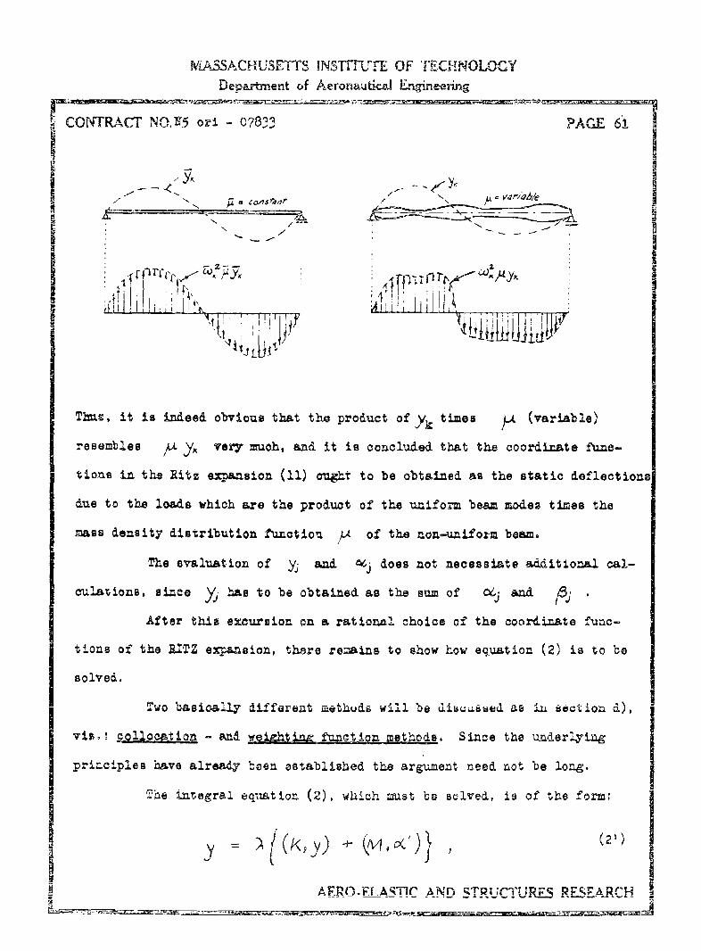
I-A3SACIAUSE-TTS INSTrfTE OF TECHNOLOGY
Department of Aeronautical _Eineerirn
CONT RACT NO.'5 on - 07833 PAC.E 61
:~PI 0 .i "
Thus, it is indeed obvious that thel product of Y,, times ýA (variable)
resembles /" Y. very =uoh, and it is concluded that the coordinate func-
tions In the Ritz expansion (11) ought to be obtained as the static deflections
due to the loads which are the product of the uniform beam modaes times the
mass density distribution function ýA of the non-uniform beam.
The evaluation of yj and 04j does not neoessiate additional cal-
culaltions, since Ya' has to be obtained as the sum of 06j and Pj .
After this excursion on a rational choice of the coordinate fumc-
tions of the RITZ expansion, there remains. to show how equation (2) is to be
solved.
Iw•o basicoslly different, aethods will be dirsused as iLl sect'ou d.),
viz.: R2ollo0alio• - an wegztLng funotiona methods. Since the underlyingg
principles have already beea established the argument need Lot be long.
The integral equaation (2), which must be solved, is of the form:
SAFRO.FF.A•_TC ANn qTRUCrTU.•E5 .RESIApr."•
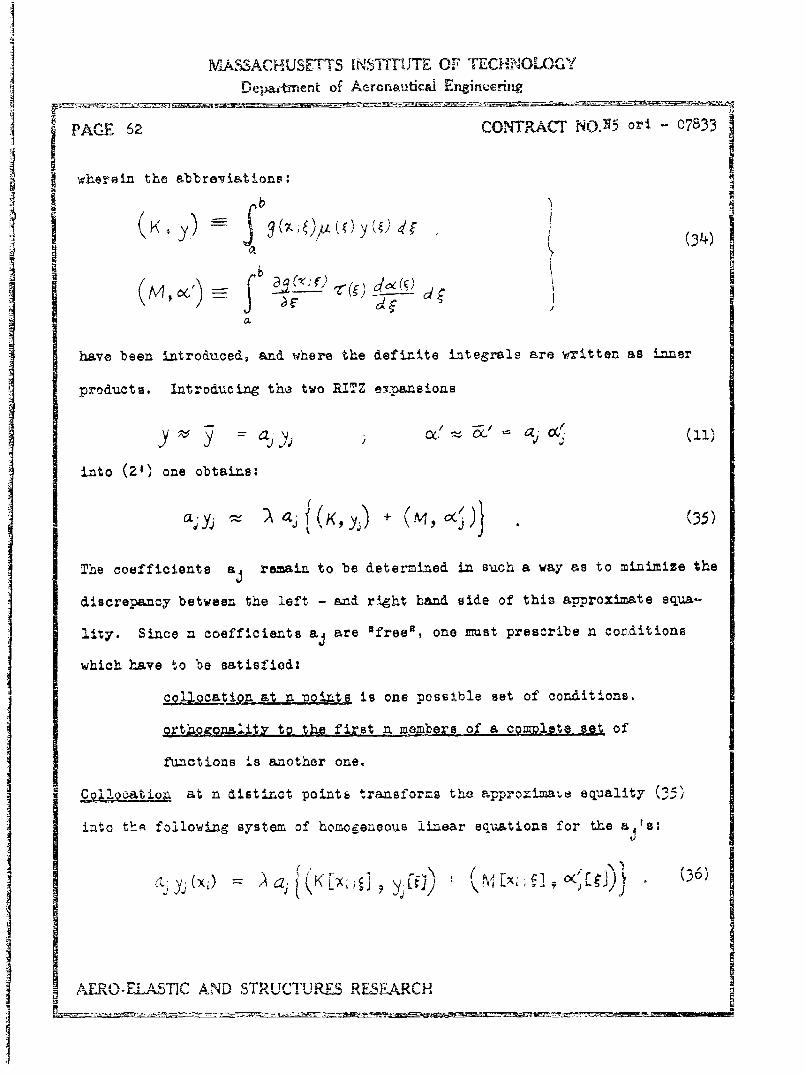
M -63ACHUSETTS INS=TUTE OF TECH-NOLOGY oDeparitment of Aeronautical Engfineeruig
PACE 62 CONTRACT No.N5) ori -07833
wherein the abbre-viations:
S_ YK ) (34)
have been introduced, and where the definite integrals are written as inner
products. Introducing the two RITZ eirpansions
y y aj j',4 aý (((
into (2') one obtains:
aý yj (35)
The coefficients aj remain to be determined in such a way as to minimize the
discrepancy between the left - and right hand side of this approximate equa-
lity,. Since n coefficients aj are "free", one must prescribe n conditions
which have to be satisfied:
cloti•n at n •p•oiAts is one possible set of conditions.
.rtho)oqAlity to the first n members of a cgmolete set of
functions is another one.
Sqllocatio& at n distinct pointE transforms the --pproxima:e equality(35)
into thE following system of homogeneous linear equations for the aF'a:
ELA STCALM' STR/TrT g'r,'E RESEARCH

MIA&SACHUSEI IS iNSTITLUTE OF TIECHNOLOGY
Dep.&rtment of Aeronautic-Ed EWir~ring
CONTRACT NO. 5 ori - 07833 PAGE 63
With the matricea and vector defined by:
witi (37)
the system (36) takes the form:
Ya= AMa (38)
where the mtri•x
N = K+ M (39)
has been introduced. The condition that (38) possesees other than the
trivial solution, a = O , ytelds the lbabda equation:
)[)y- 0 I!0 (40)
for the characteristic frequencies.
As the coordinate functions yj and OC are not linearly dependent,
the matrix Y is not singular and one can premultiply both sides of (38)
by Y- With:
equation (38) appears as:
P& \ whare P~ N(42)The associated characteristic equation ise
I'.IS.AERO-ELASTIC AND STRUCTURES RFESEARCH

MASSACHUSETTS INSTITUTr E OF TECHNOLOGYDepartneent of Aeronaudical .Engeering
gPAGE 64 CONTRACT17 NO. N5 onl - 078133
The matriLx Pis best obtainae, as solut ion PXof the matrix equation:
Y -X N x Y(44)
I where the n right nand sides are the n column vectors 9 •
'Wei7htin funotton method requires that both sides of eq. (35) be orthogonal
to n members of a complete set of functions L g5 , viz.
a.4( a,9j a 1 {K,yj) , +(M~) )}(45)
With:
= (S'i 4 KL = = K1 y K = Kg) ,(4,6)
rvxjrQt) 9 M ;N (m53 N = KNI L (K;j + 10iLj)
this reduces to the familiar generalized sigenvalue equ-ation:
ya =' &NA (47)
with the associated frequency equation (lambda equation):
ty- \aN aJý=o . (46)
IZgatn, N is not sangular, hlice one Lay also write:
PaNT U (aAH
where o ~
SAEIROS.LAWI1C AND STRUCTURES RESEARCrH

MASSACHUSETTS INST{TUTE OF TECHNOLOGlYDepartment of Aeronautical Engineering
CONTRA.CT NO. N5 ori 07813 PAGE 65
with the frequency equation;
(50)
Xf the first n members of the complete set are the functions:
0 1 2 n-1xO I, , 2, .. , x ,
it is said that one requires equality between the areas under the curves
representing the left - and right hand side of (35) and between their first
(n-2) moments about the y-axis.
Other suitable sets are the coordinate functions of the Ritz expan-
sion. If these are orthogonal a reduction of labor is effected. The expansion
functions which are reoommended for use are orthogonal with respect to the mass
distribution function 4 as a weighting function. Their construction has
been described in full detail on pg. 60.
Related to the weighting fvnction method is the modified collocation
method - outlLned on pg. 54,55 - where it is required that the integrals over
n adjacent subintervals of both sides of eq. (35) be equal. This method is,
of course, less cumbersome than the weighting function method itself, as the
integrations need not be carried out over the whole length of the bean, 'out
only over n amall portions of it. Numerical integration will have to be used
in pratt~Ale~lv all cases, and thus one integration process will yield the
eigenvalue equations, if onlv the ci.nulztive results of this numerical inte-
gration are registered at the n points. For, truly, the difference between
the partial sums at xi and xil1 is equal to the integre-l of the function over
the interval x,_, to X
9 AERO-.ELASTIC AND STRUCTURES RESEARCH

MASSACHUSET1S LNSTITUTE OF TECHNOLOGY
Departrent of Aerorulical Eneineering
A PAGE 66 CONTRACT NO. N5 ori - 07833
f) O-n the Convergence of the Collocation Method
Collocation methods have been ased& in the preceding sections with-
out. however, demonstrating that they lead to results that approximate indeed
the exact solution. R.3aders who are familiar with the Fredholm theory of in-
tegral equations will know that collocation methods are identical with the
classical treatments of linear integral equations by Volterra and Fred.holm.
(A complete presentation of these methods, and in the author's opinion - theclearest one, is given in Or. lowalewski, lnteAagleich en Berlin 1930.)
It is instructive to outline the methods once more and to state the most im-
portant findings of the theory with respect to application.
Consider that the following (non-hoaogeneous) linear integral equa-
tion has to be solved:b
f (-A'x(;y)= (yK)
in the interval a :- x - b. Let x be a point In the interval ja,b]
Then at x - i the equation:
is certainly satisfied. Replace the integral by an approximating slun:
b n
AERO-EJ_.STIC AND 3TRUCTURES RES-E.A5RCH

MASSACHUSETTS INSTITUTE OF TECHNOLOGYDepa-otmnent of Aeronautical Enineering
ICONITRlACT NO. V5 or - 07833 PAGE 67
and. let the interval [ab] be subdtvided into n equal intervals, then one
obtains the following n einultaneoixa eqationa.
flx,) K2X2 y~j fj) n~ =ý 0
which are satisfied only approximately by the exact solutions of the integral
equation. xi and yj take on all values a+k(b-a)/n; (k = 1,2,..,n):
independently. With = .=;Kij =-K(Xý;yj)1FG,7IyJ
one arrives at the equations: + 2- Kzj f3 = or written out in full3
KLI + (1+ K2.1 ,
KK m2.fj2 + + qn
Cramer's rule gives the solutions of this system as:
r D (r n)....., n)
where D is the determinant of the coefficients of the unknowne, and Dr is
obtained from D by replacing the r-th column infl) by gt2-'9
(1.+ K,) K,1 ' K,, I(I+K ". Kr,., g, K,.r+i .. K,,,
K2 (t 4) K Kn KI1 -I5.. Kzrt4 Km
km = -I..f') j'~. n .II]) = ... ... . .. ......... .r.
KMI K 7,X+ " •")l K•"r~f I "~~-,"i~ •• Kr I- ST% r" r , n n"
AER.ELASICAND STRZUCT--URES RESEACH.~

MASSACHUSETrS INSTITUTE OF TECHNOLOGYDepanment of Aeronautical Engineering
PAGE 68 CONTRACT NON5 ori =07833
Suppose ths f£have been calczulated, based on a subdivision of the
interval ia , bj into n equal parts, and the values of the ordinates are connect]
ed by straight lines, as the following sketch illustrates.
-- he question arises now as to what
happens if the subdivision is madebL [ smaller and smaller.
This necessitates the investigation of the so-called Fredholm determinant of
the Kernel K(x,y) which is the limit of D as the number n of subdivisions of
r"La,bh tends to infinity.
The Fredholm theory ascertains the uniform convergence of the
anproximative solutions towards the exact solution as the subdivisions of the
interval [a,bl become smaller and smaller.
This important result justifies the collocation method-
g) The Method. of Station Functioans (another method of constructing
coordinate functions for the RITZ expansion)
Q.tite frequentlv one finds the suggestion that the so-called station
function method yields suitable coordinate functions for the RITZ expansion.
This recommendation will now be examined critically.
Recall that the convergence of the RITZ expansion is best, if the
assumed functions are as close as possible to the actual eigenfunctions of the
problem under investigation. In section e) it was suggested that the eigen=
iunctions of a Hneighboring5 problem be used to construct an approximation to
the node-loads of the actual problem, and thcn to calculate the coordinate
:Lactions as t'e static deflections under th.ese loads. These offer the great
ACCn1 . 1 AT• •N STRUCTUR ES .EAFDRCH

MIASSACHUSE'J-S iNbI fUT E OF TECHNOLOGYDepartment of AeronauticM Engineering
I COWtRACT NON5 o o -783 PAGE 69O
advantage of being orthogonal fýxnctiorn, thereby reducing the numerical ca!
culations to solve the matrix eigenvalue equation. But furthermore they are
already close to the actual modes. The station function method is now dove=-
loped.
Suppose the linear homogeneous integral equation (Fredholm equation
of the second kind) has to be solved,
i(N) f Y y(51)
where the kernel K(x,y) is given. As in the Fredholm theory, replace the in-
tegral equation by a set of n linear homogeneous equations. The solution to
this set does not satisfy the integral equation exactly. Through the n points
son interpolation function can be fitted which permits the determination of
functional values at all points between a and b. Since n homogeneous linear
equations admit, in general, n solutions which correspond to the n zootg of
the characteristic equation, one provides for this fact by writing the solu-
tion as a linear aggregate of n interpolation functions:
ý (X) -ý(ý ;() (52)
Because f(x) mut take on the value f(xi) for x xi, it is apparent that the
functions gex) are sabject to the requirement:
jJ .00 eJ (53)
The functions g4 have to satisfy the boundary conditions and should, if
possible, be identical with the nor.al functions of the problem. It ia re-
called that the kernel functioL is an "elementary solution' of the problem
F.RO-A_.A•TC AND STRUCTURRS DLr- ARCHru

MASSACHUSETTS INSTTFIUE OF TECH-1OLOGY
Deparbnent of Aeronauticai EngineeringSPAGE 70• - .... C•• • •ONTACT N•O,5 or - 0783/3
from which all solutione can be built up by means of the superpositioA prin -
ciple. If h j(z) is a load-funatiou, then
j jKx.y hi (j)dyis a solution of the problem which satisfies all boundary conditions. As a
matter of fact, this integral represents the effect due to the cause hi X).
Since every gi(x) has to satisfy n conditions, viz.
and. a total of n functions gi(x) have to be constructed, n2 free parameters
must be chosen such that all these conditions can be fulfilled. Consequently
the gi's must have the form:b
04JK (X J) hj (y) dy ,(54f)a
where the load functions hj(x) are given functions. They ought to be approxi-
mations to the mode-loads, under which condition the diagonal elements aii of
the matrix A a (a ) will be much larger than the other ones.
One is now left with the task of evaluating the matrix A so as to
Imake gj(Xj = ei* Let 3 be the vector: t he
vector {~M,..,~ with an element Z X/ y j()d then theN a
equations (54) appear as:
If x takes on the values xl, x2,...,xn this becomes a set of n sizultaneous
equations. With the definitions: L9 4 = (') g1 j ) L ,they are coa-
veniently written as Ai (55)
SAERO-ELASTMC AND STRUCTURES RESEARCH

MASSA,,U , ,hY 'eINSTITILE OF TECHNOLOGYDepairtment of Aeron-au. "a- Engineering
CONTRACT NO. N5 orl - 07833 PAGE 71
I-V ew f qaion G5) is the unit Matniz % axr.d tbýs 1
is the reciprocal of '
A (56)
Where d fr/and k L K( 1 y Khyu
(Noto the order of the indicesl) Once the al,'s are knowu, one may substi-
tute eq. (54) into eq. (51) to obtain:
b
or also:i b
-KXNgL()d (57')a.
This equation has to be satisfied for all x, especially for x = xj (J =,
... ,'n) and It possesses a non-trival solution only if
,etL-et. -4-2I = 0 -(wh~ere! f(xj) = f4) (58)
is satisfied, The roots of the frequency equation detormine n sets of solu-
t lonB f whieh, when substituted. Into (.52)~ give a continuous approxima-
tion to the solutiions of the integral equation.
Thb inteorations occuring in (58) will, ix general, have to be
carried. out numerically. Gaussi&n qtyadrature yields the highest degree of
accuracF for a given number of integration stations. it wil, however, sel-
dom be applied, because the values of the function will be given at equal
intervals. In ay case, the number of integration stations hap to be large
AERO.ELASTIC AND STRUCTURES R.ESEARCH!

MASSACHUSETTS INSTITUTE OF TECHNOLOGY
Department of Aeronautical Engineering
PAGE 72 - CO NTRACT NO.N5 o - 07833
enough wo render the error of the numerical integration insignificant compared
with the approximation introduced with (52).
It is apparent that the station function method is very laborious.
In the present problem its application is not justified, because exact solu-
tions of neighboring problems can be found readily and be used in a RITZ expan-
sion. The merits of the station function method lie in flutter analysis of
aircraft wings and not in the vibration analysis of beams. There the method,
extended to two independent variables (planar problems) is really useful, for
usually only the lowest frequency is of interest and coordinate functions to
be utilized in a RITZ expansion are not easy to find.
4. Limitation of the Analytical Methods
In section 1) of this chapter five restrictions have been found that
must be imposed upon the vibrating beam in order that the present analysis be
applicable and it had been stated that other restrictions, of dynamical nature,
would be formulated later. To these attention is now turned. Recall briefly
the "integral methods" that have been outlined, viz. the variational method
and the integral equation method. The-first of these states that the total
energy of the vibrating body must be a minirz for every natural mode. The
second states that the natural modes are the characteristic solutions of an
Integral equation which represents al! possible vibrations of the body. The
unknown solutions are wrIttsn as linear aggregates of known vibrations and
the problem immediately arises of determining the degree of participation of
theee known vibrations in order to build up the desired solutions. This leads
then to an algebraic problem of solving a matrix eigenvalue equation. Every
solution vector corresponds to characteristic solution of the problam. 0ne
AERO.-ELASTI'C- Ai-ND STRUCTUERLJ'ý RRESLIC11

MASSACHUSE7T INS =11TUTE OF TPECHNOLOG,
Departynent of Aeronautical Engineering
CONTRACT NO. N5 art - 07833 PAGE7 7_
wov3& be tampted to believe that any desired degree of accuracy can be obtalned.i
if only the Ritz expansion (i.s. the 1Lnear aggregate) comprised a sufficientlyr
la'ge number of linearly independent functions and corresponding particiDation
factors. But this is not sol Suppose that a Ritz expansion contains twenty
members and. that the eigenvalue problem has been solved. Then one may write
down the expansion of the, say, tenth natural mode of the beam and one knows
from mathematical reasoning that this ought to be a very good approximationI
to this mode, if the linear aggregate represents the solutions of a neighbor-
ing problem. Let the beam under investigation have a length of ten times iLb
average height. Under these assumptions a half-wave of the tenth mode has a
length of about one tenth of the span of the beam. Therefore, the nodal
points subdivide the beam into sections with a length to height ratio of
approximately one to one. Between two adjacent nodal points the beam deflects
as if it were a portion of a continuous beam simply supported at the nodal
points. The simplified beam theory is, however, not applicable to such stubby Ibeams, since the stress-str-sin distribution across the beam is no longer
linear. Shear deformation becomes so great that the warping of the cross
sections can no longer be neglected. Furthermore the normal stresses perpen-
dicula., to the beam axis must be considered. This means that a solution satis-
fying •he rigor of the mathematical theory of elasticity is called for. Un-
fortunately no such vibration solutions havz been found and it is not possible
to compare the engineering solution with the elasticity solution directl4.
Bending problems, however, have bwen solved in great number and there it was
found that as long as the beam haB a length of more than three times its aver-
age depths, the engineerimg form- 1.s give a reasonable approximation to the
ARO-ELASTI1_, C AND STRUCTUPE5 RFSEFL.CH
MASSACHUSE17TTS INSTIUJTE OF TECHNOLOGYDepartment of AeronauticCl En4ineerins
PAGE 74 CONTRACT NOS5 ori - 07533
behavior of the beez. The factor three cannot be taken religiously, for it
depends on the boundary conditions, the geometry of the beam; and. the degree
Sof accu-racy required. It is reasonable to assume that the vibration analysis
S obeys the same general restrictions as the static deflection analysis and,
S until more constraining requirements can be derived from exact analysis, it is
recommended that only those modes should be calcuilated by the methods developed
in thui report which yield half-wave lengths that are long in comparison to the
average depth of the beam (i.e. at least three to five times the &epts4.
The restriction just voiced should Lot mislead th3 an lyst to the
conclusion that is is useless to carry man terms in a RITZ expansion, believ-
ing that the higher terms represent the higher modes of the beam. This is not
true, for, if one had an analytical expression in closed form, say of the first
mode, and expanded this into a uniformly converging series and used the expan-
sion instead of the closed form in the calculations, then certainly all terms
of the expansion are needed to represent the mode properly. The limitation of
the method is of a different nature. It states only that the lower modes can
be calculated by the formulas given, because the equations are valid only in
a domain of low frequencies. Higher frequencies and modes do exist but they
cannot be calculated with a vibration theory thAt is based upon a simplified
boam analysts.
Furthermore, it must be emphasized that the beams to be Investigated
have to possess a symmetric cross section and the vibrating has to occur in
"the plane of symmetry. Zccemtric, fixed loads on the be*. ares thus to be
excluded, as no coupling of bending - and torsional vibrations Ie permissible.
AERO.ELA-STIC AND STRUCTURES RESEARCH

MASSACHUSETTS INST7TUTE OF TECHNOLOGYDepartment of Aeronavutical Enigineering
r ONTRACT NO.N5 oni 07C833 PAGE ?5
Only recently R. Heilig, Ingenieur- Archiv, vol. 19, pg. 231-254, (1951), has
&evelope! a rigorous solution for the coupled torsion-bending vibration of
prismatic, thin-walled, open-profile beams, taking proper account of the
warping stresses. An extension of this theory to prismatic bars of arbitrary
cross section encounters great difficulties which arise from the fact that,
at present, it is not possible to calculate the stress distribution in a pris-
matic bar of arbitrary cross section, with arbitrary boundary conditions, due
to bending and torsion. Efforts ought to be made in this direction, and the
above mentioned paper gives a good starti-.g ground.
The findings of this report are summarized in the following:
Lemm: The methods presented. in this report are applicable to straight beams
with symmetric cross section which vibrate in the plane of symmetry. They
yield satisfactory results for modes whose half-"ave length is long in compari-
son to the average height of the beam.
AERO-ELASTIC AND STRUCTURES RESEARCH

PLA(iU Cm1-3 INTITUT E OF Ti,-CPJ4OLOSYDorL-'N-ent of Ae~onautiica Lgrainecrnw
COPTA tj, Z5ori 07833
3 i A, M. Tftelkg.
4- + +
cc - . N i
0%~V V;6&o
co rcc
*N~Q I NN -
+11111 +11 7
qd0U
gat 0, - .T;
IV cc Wl e, 40 OD S
V-9:
IL414 ItM 4 4-1N m C
N&M A W~N p' N tx #A
0a0000---- - - 1 -I
N~ ~ 4 4.N- 594n'CIA
0 H- 0
tit It A t~ ;i t O O
AE- G4&AMWC AM 3 ~T UWChht'! -IUMIE A%ýP

K R CEYOp
I r07 7