Embed Size (px)
Citation preview
UML Notation Guide
Chapter 4
4. STATIC STRUCTURE DIAGRAMS
4.1 Class diagram4.2 Object diagram4.3 Class4.4 Name Compartment4.5 List Compartment4.6 Type4.7 Interfaces4.8 Parameterized Class (Template)4.9 Bound Element4.10 Utility4.11 Metaclass4.12 Class Pathnames4.13 Importing a package4.14 Attribute4.15 Operation4.16 Association4.17 Binary Association4.18 Association Role4.19 Multiplicity4.20 Qualifier4.21 Association Class4.22 N-ary association4.23 Composition4.24 Generalization4.25 Dependency 554.26 Refinement Relationship4.27 Derived Element4.28 Navigation Expression
UML Notation Guide v1.0 Chapter 4
http://www.essaim.univ-mulhouse.fr/uml/documentation/version1.0/notation/notation_guide_ch4.html (1 of 35) [09/09/2000 12:58:31 PM]
4. STATIC STRUCTURE DIAGRAMSClass diagrams show the static structure of the model, in particular, the things that exist (such asclasses and types), their internal structure, and their relationships to other things. Class diagrams donot show temporal information, although they may contain reified occurrences of things that have orthings that describe temporal behavior. An object diagram shows instances compatible with aparticular class diagram.
This chapter includes classes and their variations, including templates and instantiated classes, and therelationships between classes: association and generalization. It includes the contents of classes:attributes and operations. It also includes the organizational unit of class diagrams: packages.
4.1 Class diagram
A class diagram is a graph of modeling elements shown on a two-dimensional surface. (Note that a''class'' diagram may also contain types, packages, relationships, and even instances, such as objectsand links. Perhaps a better name would be ''static structural diagram'' but ''class diagram'' soundsbetter.)
4.1.1 Notation
A class diagram is a collection of (static) declarative model elements, such as classes, types, and theirrelationships, connected as a graph to each other and to their contents. Class diagrams may beorganized into packages either with their underlying models or as separate packages that build uponthe underlying model packages.
4.2 Object diagram
An object diagram is a graph of instances. A static object diagram is an instance of a class diagram; itshows a snapshot of the detailed state of a system at a point in time. A dynamic object diagram showsthe detailed state of a system over some period of time, including the changes that occur over time;dynamic object diagrams are manifested as collaboration diagrams.
There is no need for tools to support a separate format for object diagrams. Class diagrams can containobjects, so a class diagram with objects and no classes is an ''object diagram.'' Collaboration diagramscontain objects, so a collaboration diagram with no messages is an ''object diagram.'' The phrase isuseful, however, to characterize a particular usage achievable in various ways.
4.3 Class
A class is the descriptor for a set of objects with similar structure, behavior, and relationships. UMLprovides notation for declaring classes and specifying their properties, as well as using classes invarious ways. Some modeling elements that are similar in form to classes (such as types, signals, orutilities) are notated as stereotypes of classes. Classes are declared in class diagrams and used in mostother diagrams. UML provides a graphical notation for declaring and using classes, as well as a textualnotation for referencing classes within the descriptions of other model elements.
UML Notation Guide v1.0 Chapter 4
http://www.essaim.univ-mulhouse.fr/uml/documentation/version1.0/notation/notation_guide_ch4.html (2 of 35) [09/09/2000 12:58:31 PM]
4.3.1 Semantics
The name of a class has scope within the package in which it is declared and the name must be unique(among class names) within its package.
4.3.2 Basic notation
A class is drawn as a solid-outline rectangle with 3 compartments separated by horizontal lines. Thetop name compartment holds the class name and other general properties of the class (includingstereotype); the middle list compartment holds a list of attributes; the bottom list compartment holds alist of operations.
References. By default a class shown within a package is assumed to be defined within that package.To show a reference to a class defined in another package, use the syntax
Package-name::Class-name
as the name string in the name compartment. A full pathname can be specified by chaining togetherpackage names separated by double colons (::).
4.3.3 Presentation options
Either or both of the attribute and operation compartments may be suppressed. A separator line is notdrawn for a missing compartment. If a compartment is suppressed, no inference can be drawn aboutthe presence or absence of elements in it.
Additional compartments may be supplied as a tool extension to show other predefined or user-definedmodel properties, for example, to show business rules, responsibilities, variations, events handled, andso on. Most compartments are simply lists of strings. More complicated formats are possible, but UMLdoes not specify such formats; they are a tool responsibility. Appearance of each compartment shouldpreferably be implicit based on its contents. Tools may provide explicit markers if needed.
Tools may provide other ways to show class references and to distinguish them from classdeclarations.
A class symbol with a stereotype icon may be ''collapsed'' to show just the stereotype icon, with thename of the class either inside the class or below the icon. Other contents of the class are suppressed.
4.3.4 Style guidelines
Class name in boldface, centered.
Stereotype name in plain face, within guillemets, centered.
Typically class names begin with an uppercase letter.
Attributes and operations in plain face, left justified.
Typically attribute and operation names begin with a lowercase letter.
UML Notation Guide v1.0 Chapter 4
http://www.essaim.univ-mulhouse.fr/uml/documentation/version1.0/notation/notation_guide_ch4.html (3 of 35) [09/09/2000 12:58:31 PM]
As a tool extension, boldface may be used for marking special list elements, for example, to designatecandidate keys in a database design. This might encode some design property modeled as a taggedvalue, for example.
Strings for the names of abstract classes or the signatures of abstract operations in italics.
Show full attributes and operations when needed and suppress them in other contexts or references.
4.3.5 Example
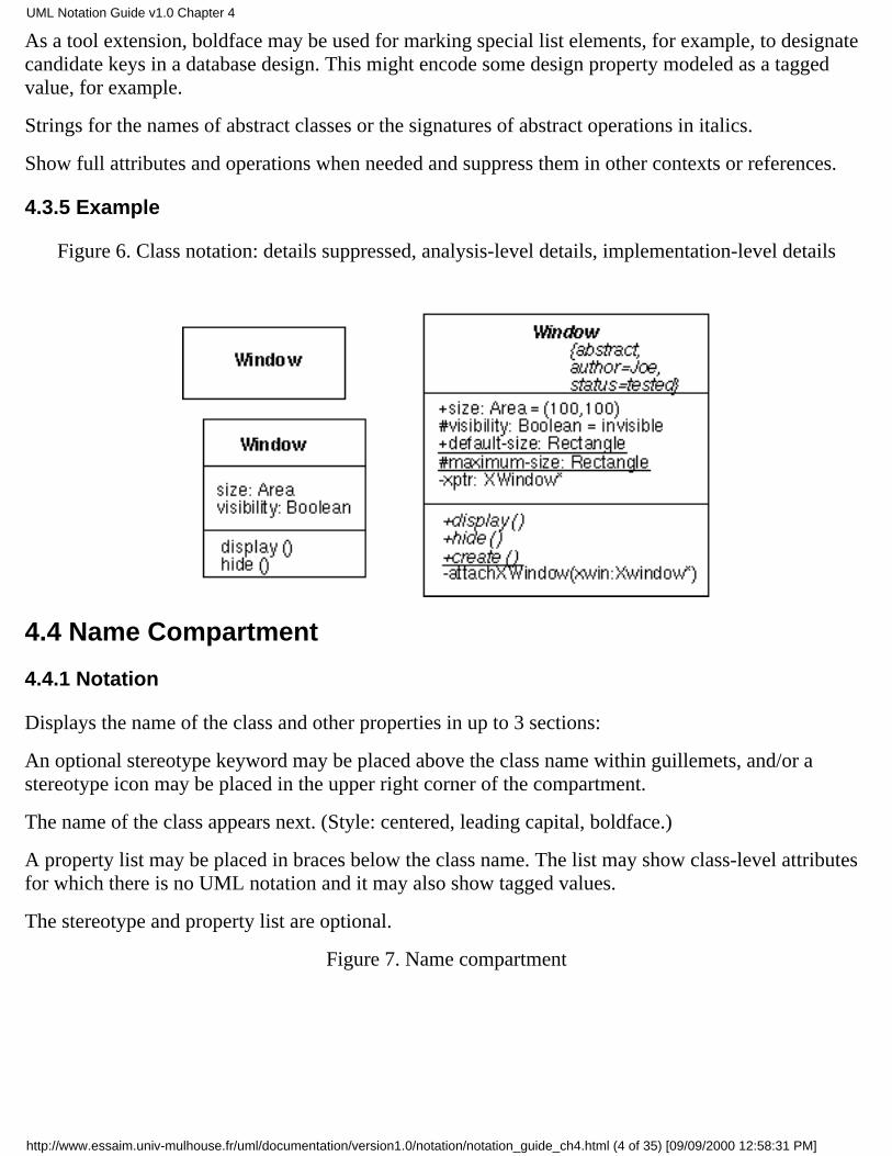
Figure 6. Class notation: details suppressed, analysis-level details, implementation-level details
4.4 Name Compartment
4.4.1 Notation
Displays the name of the class and other properties in up to 3 sections:
An optional stereotype keyword may be placed above the class name within guillemets, and/or astereotype icon may be placed in the upper right corner of the compartment.
The name of the class appears next. (Style: centered, leading capital, boldface.)
A property list may be placed in braces below the class name. The list may show class-level attributesfor which there is no UML notation and it may also show tagged values.
The stereotype and property list are optional.
Figure 7. Name compartment
UML Notation Guide v1.0 Chapter 4
http://www.essaim.univ-mulhouse.fr/uml/documentation/version1.0/notation/notation_guide_ch4.html (4 of 35) [09/09/2000 12:58:31 PM]

4.5 List Compartment
4.5.1 Notation
Holds a list of strings, each of which is the encoded representation of an element, such as an attributeor operation. The strings are presented one to a line with overflow to be handled in a tool-dependentmanner. In addition to lists of attributes or operations, lists can show other kinds of predefined oruser-defined values, such as responsibilities, rules, or modification histories. The manipulation ofuser-defined lists is tool-dependent.
The items in the list are ordered and the order may be modified by the user. The order of the elementsis meaningful information and must be accessible within tools. For example, it may be used by a codegenerator in generating a list of declarations. The list elements may be presented in a different order,however, to achieve some other purpose. For example, they may be sorted in some way. Even if thelist is sorted, however, the items maintain their original order in the underlying model; the orderinginformation is merely suppressed in the view.
An ellipsis ( . . . ) as the final element of a list or the final element of a delimited section of a listindicates that there exist additional elements in the model that meet the selection condition but that arenot shown in that list. Such elements may appear in a different view of the list.
Group properties: A property string may be shown as a element of the list, in which case it applies toall of the succeeding list elements until another property string appears as a list element. This isequivalent to attaching the property string to each of the list elements individually. The property stringdoes not designate a model element. Examples of this usage include indicating a stereotype andspecifying visibility. Stereotype strings may also be used in a similar way to qualify subsequent listelements.
4.5.2 Presentation options
A tool may present the list elements in a sorted order, in which case the inherent ordering of theelements is not visible. A sort is based on some internal property and does not indicate additionalmodel information. Example sort rules include alphabetical order, ordering by stereotype (such asconstructors, destructors, then ordinary methods), ordering by visibility (public, then protected, thenprivate), etc.
The elements in the list may be filtered according to some selection rule. The specification of selectionrules is a tool responsibility. The absence of items from a filtered list indicates that no elements meetthe filter criterion, but no inference can be drawn about the presence or absence of elements that do notmeet the criterion (however, the ellipsis notation is available to show that invisible elements exist). Itis a tool responsibility whether and how to indicate the presence of either local or global filtering,
UML Notation Guide v1.0 Chapter 4
http://www.essaim.univ-mulhouse.fr/uml/documentation/version1.0/notation/notation_guide_ch4.html (5 of 35) [09/09/2000 12:58:31 PM]
although a stand-alone diagram should have some indication of such filtering if it is to beunderstandable.
If a compartment is suppressed, no inference can be drawn about the presence or absence of itselements. An empty compartment indicates that no elements meet the selection filter (if any).
Note that attributes may also be shown by composition (see Figure 20).
4.5.3 Example
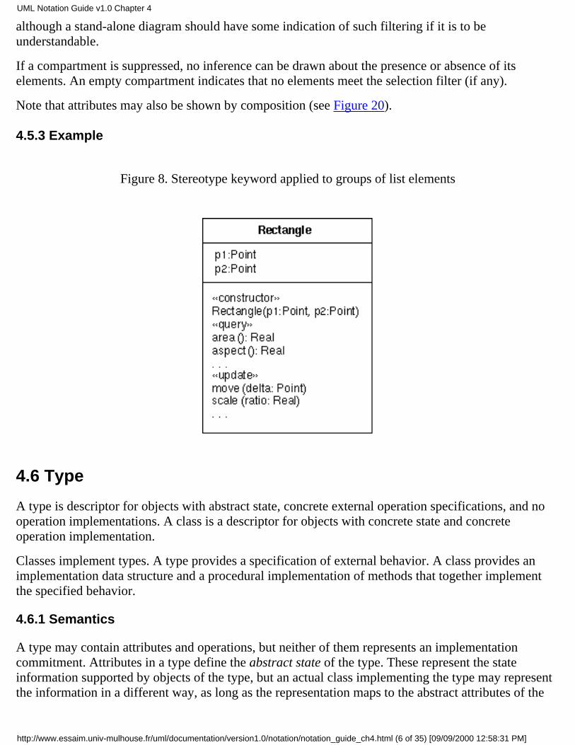
Figure 8. Stereotype keyword applied to groups of list elements
4.6 Type
A type is descriptor for objects with abstract state, concrete external operation specifications, and nooperation implementations. A class is a descriptor for objects with concrete state and concreteoperation implementation.
Classes implement types. A type provides a specification of external behavior. A class provides animplementation data structure and a procedural implementation of methods that together implementthe specified behavior.
4.6.1 Semantics
A type may contain attributes and operations, but neither of them represents an implementationcommitment. Attributes in a type define the abstract state of the type. These represent the stateinformation supported by objects of the type, but an actual class implementing the type may representthe information in a different way, as long as the representation maps to the abstract attributes of the
UML Notation Guide v1.0 Chapter 4
http://www.essaim.univ-mulhouse.fr/uml/documentation/version1.0/notation/notation_guide_ch4.html (6 of 35) [09/09/2000 12:58:31 PM]
type. Type attributes can be used to define the effects of type operations. A type may containspecifications for operations, including their signatures and a description of their effects, but theoperations do not contain implementations. The effect of an operation is defined in terms of thechanges it makes to the abstract attributes of the type.
It is sometimes helpful to describe abstract properties that represent structured information. Forexample, a type might contain a PriceList attribute that maps product names to money. The types ofthese attributes can be treated as mathematical functional mappings, such as ProductName-->Money.
A type establishes a behavioral specification for classes. A class that supports the operations definedby a type is said to implement the type; this relationship can be shown as a form of refinementrelationship from the class to the type that it implements.
4.6.2 Notation
A type shown as a stereotype of a class symbol with the stereotype «type».
A type may contain lists of abstract attributes and of operations.
A type may contain a context and specifications of its operations accordingly.
4.7 Interfaces
An interface is the use of a type to describe the externally-visible behavior of a class, component, orother entity (including summarization units such as packages).
4.7.1 Notation
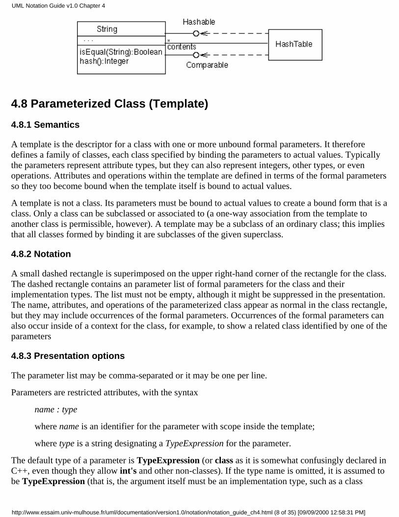
An interface may be displayed using a small circle with the name of the type. This notation stresses theoperations provided by the type. An interface may supply one or more operations. The circle may beattached to classes (or higher-level containers, such as packages that contain the classes) that support itby a solid line. This indicates that the class provides all of the operations in the interface type (andpossibly more). The operations provided are not shown on the circle notation; use the full rectanglesymbol to show the list of operations. A class that requires the operations in the interface may beattached to the circle by a dashed arrow. The dashed arrow indicates a sufficiency test: if the typeprovides at least these operations then a class that realizes it will work. The dependent class is notrequired to actually use all of the operations.
An interface is a type and may also be shown using the full rectangle symbol with compartments. Thecircle form may be regarded as a shorthand notation.
4.7.2 Example
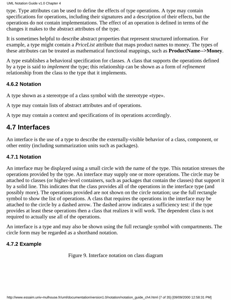
Figure 9. Interface notation on class diagram
UML Notation Guide v1.0 Chapter 4
http://www.essaim.univ-mulhouse.fr/uml/documentation/version1.0/notation/notation_guide_ch4.html (7 of 35) [09/09/2000 12:58:31 PM]
4.8 Parameterized Class (Template)
4.8.1 Semantics
A template is the descriptor for a class with one or more unbound formal parameters. It thereforedefines a family of classes, each class specified by binding the parameters to actual values. Typicallythe parameters represent attribute types, but they can also represent integers, other types, or evenoperations. Attributes and operations within the template are defined in terms of the formal parametersso they too become bound when the template itself is bound to actual values.
A template is not a class. Its parameters must be bound to actual values to create a bound form that is aclass. Only a class can be subclassed or associated to (a one-way association from the template toanother class is permissible, however). A template may be a subclass of an ordinary class; this impliesthat all classes formed by binding it are subclasses of the given superclass.
4.8.2 Notation
A small dashed rectangle is superimposed on the upper right-hand corner of the rectangle for the class.The dashed rectangle contains an parameter list of formal parameters for the class and theirimplementation types. The list must not be empty, although it might be suppressed in the presentation.The name, attributes, and operations of the parameterized class appear as normal in the class rectangle,but they may include occurrences of the formal parameters. Occurrences of the formal parameters canalso occur inside of a context for the class, for example, to show a related class identified by one of theparameters
4.8.3 Presentation options
The parameter list may be comma-separated or it may be one per line.
Parameters are restricted attributes, with the syntax
name : type
where name is an identifier for the parameter with scope inside the template;
where type is a string designating a TypeExpression for the parameter.
The default type of a parameter is TypeExpression (or class as it is somewhat confusingly declared inC++, even though they allow int's and other non-classes). If the type name is omitted, it is assumed tobe TypeExpression (that is, the argument itself must be an implementation type, such as a class
UML Notation Guide v1.0 Chapter 4
http://www.essaim.univ-mulhouse.fr/uml/documentation/version1.0/notation/notation_guide_ch4.html (8 of 35) [09/09/2000 12:58:31 PM]
name). Other parameter types (such as Integer) should be explicitly shown.
4.8.4 Example
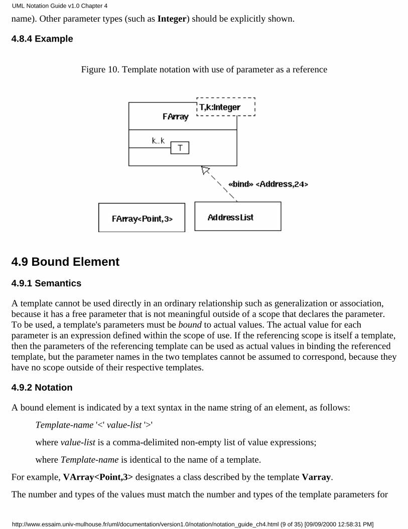
Figure 10. Template notation with use of parameter as a reference
4.9 Bound Element
4.9.1 Semantics
A template cannot be used directly in an ordinary relationship such as generalization or association,because it has a free parameter that is not meaningful outside of a scope that declares the parameter.To be used, a template's parameters must be bound to actual values. The actual value for eachparameter is an expression defined within the scope of use. If the referencing scope is itself a template,then the parameters of the referencing template can be used as actual values in binding the referencedtemplate, but the parameter names in the two templates cannot be assumed to correspond, because theyhave no scope outside of their respective templates.
4.9.2 Notation
A bound element is indicated by a text syntax in the name string of an element, as follows:
Template-name '<' value-list '>'
where value-list is a comma-delimited non-empty list of value expressions;
where Template-name is identical to the name of a template.
For example, VArray<Point,3> designates a class described by the template Varray.
The number and types of the values must match the number and types of the template parameters for
UML Notation Guide v1.0 Chapter 4
http://www.essaim.univ-mulhouse.fr/uml/documentation/version1.0/notation/notation_guide_ch4.html (9 of 35) [09/09/2000 12:58:31 PM]
the template of the given name.
The bound element name may be used anywhere that an element name of the parameterized kind couldbe used. For example, a bound class name could be used within a class symbol on a class diagram, asan attribute type, or as part of an operation signature.
Note that a bound element is fully specified by its template, therefore its content may not be extended;declaration of new attributes or operations for classes is not permitted, for example, but a bound classcould be subclassed and the subclass extended in the usual way.
The relationship between the bound element and its template may alternatively be shown by arefinement relationship with the stereotype «bind». The arguments are shown on the relationship. Inthis case the bound form may be given a name distinct from the template.
4.9.3 Style guidelines
The attribute and operation compartments are normally suppressed within a bound class, because theymust not be modified in a bound template.
4.9.4 Example
See Figure 10.
4.10 Utility
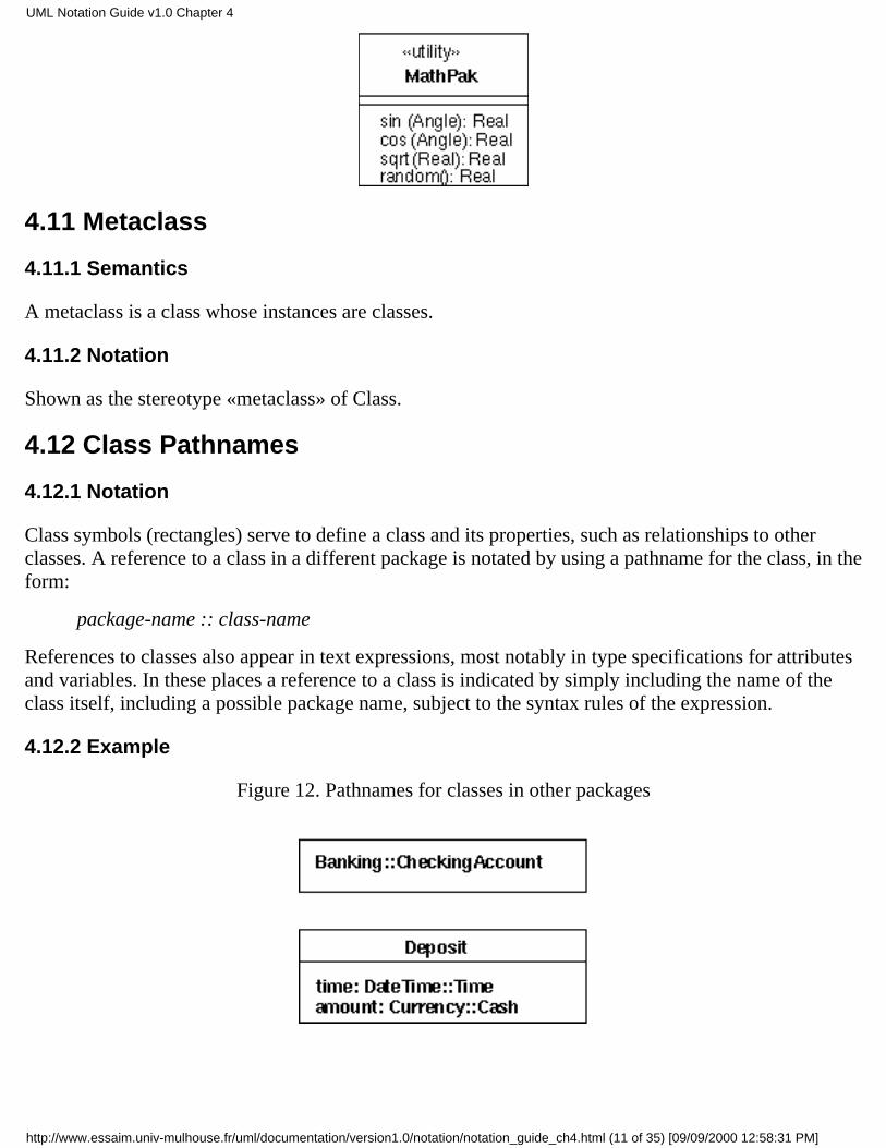
A utility is a grouping of global variables and procedures in the form of a class declaration. This is nota fundamental construct but a programming convenience. The attributes and operations of the utilitybecome global variables and procedures. A utility is modeled as a stereotype of a class.
4.10.1 Semantics
The instance-scope attributes and operations of a utility are interpreted as global attributes andoperations. It is inappropriate for a utility to declare class-scope attributes and operations because theinstance-scope members are already interpreted as being at class scope.
4.10.2 Notation
Shown as the stereotype «utility» of Class. It may have both attributes and operations, all of which aretreated as global attributes and operations.
4.10.3 Example
Figure 11. Notation for utility
UML Notation Guide v1.0 Chapter 4
http://www.essaim.univ-mulhouse.fr/uml/documentation/version1.0/notation/notation_guide_ch4.html (10 of 35) [09/09/2000 12:58:31 PM]
4.11 Metaclass
4.11.1 Semantics
A metaclass is a class whose instances are classes.
4.11.2 Notation
Shown as the stereotype «metaclass» of Class.
4.12 Class Pathnames
4.12.1 Notation
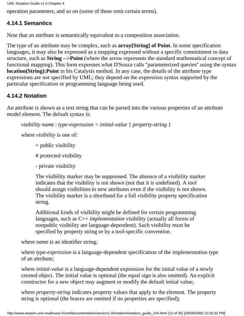
Class symbols (rectangles) serve to define a class and its properties, such as relationships to otherclasses. A reference to a class in a different package is notated by using a pathname for the class, in theform:
package-name :: class-name
References to classes also appear in text expressions, most notably in type specifications for attributesand variables. In these places a reference to a class is indicated by simply including the name of theclass itself, including a possible package name, subject to the syntax rules of the expression.
4.12.2 Example
Figure 12. Pathnames for classes in other packages
UML Notation Guide v1.0 Chapter 4
http://www.essaim.univ-mulhouse.fr/uml/documentation/version1.0/notation/notation_guide_ch4.html (11 of 35) [09/09/2000 12:58:31 PM]

4.13 Importing a package
4.13.1 Semantics
A class in another package may be referenced. On the package level, the \xc7 imports\xc8 dependencyshows the packages whose classes may be referenced within a given package or packages recursivelyembedded within it. The target references must be exported by the target package. Note that exportsare not recursive; they must be propagated up across each level of containment. Imports are recursivewithin inner levels of containment. (See the semantics document for full details.)
4.13.2 Notation
The imports dependency is displayed as a dependency arrow from the referencing package to thepackage containing the target of the references. The arrow has the stereotype «imports».
A package controls the external visibility of its contents. An item can be imported into package if it ismade visible (''exported'') by its declaring package. There is no special UML notation for the visibilityof items within a package. Rather a view can be constructed showing the publicly available items froma package.
4.13.3 Example
Figure 13. Imports dependency among packages
4.14 Attribute
Used to show attributes in classes. A similar syntax is used to specify qualifiers, template parameters,
UML Notation Guide v1.0 Chapter 4
http://www.essaim.univ-mulhouse.fr/uml/documentation/version1.0/notation/notation_guide_ch4.html (12 of 35) [09/09/2000 12:58:32 PM]
operation parameters, and so on (some of these omit certain terms).
4.14.1 Semantics
Note that an attribute is semantically equivalent to a composition association.
The type of an attribute may be complex, such as array[String] of Point. In some specificationlanguages, it may also be expressed as a mapping expressed without a specific commitment to datastructure, such as String -->Point (where the arrow represents the standard mathematical concept offunctional mapping). This form expresses what D'Souza calls ''parameterized queries'' using the syntaxlocation(String):Point in his Catalysis method. In any case, the details of the attribute typeexpressions are not specified by UML; they depend on the expression syntax supported by theparticular specification or programming language being used.
4.14.2 Notation
An attribute is shown as a text string that can be parsed into the various properties of an attributemodel element. The default syntax is:
visibility name : type-expression = initial-value { property-string }
where visibility is one of:
+ public visibility
# protected visibility
- private visibility
The visibility marker may be suppressed. The absence of a visibility markerindicates that the visibility is not shown (not that it is undefined). A toolshould assign visibilities to new attributes even if the visibility is not shown.The visibility marker is a shorthand for a full visibility property specificationstring.
Additional kinds of visibility might be defined for certain programminglanguages, such as C++ implementation visibility (actually all forms ofnonpublic visibility are language-dependent). Such visibility must bespecified by property string or by a tool-specific convention.
where name is an identifier string;
where type-expression is a language-dependent specification of the implementation typeof an attribute;
where initial-value is a language-dependent expression for the initial value of a newlycreated object. The initial value is optional (the equal sign is also omitted). An explicitconstructor for a new object may augment or modify the default initial value;
where property-string indicates property values that apply to the element. The propertystring is optional (the braces are omitted if no properties are specified);
UML Notation Guide v1.0 Chapter 4
http://www.essaim.univ-mulhouse.fr/uml/documentation/version1.0/notation/notation_guide_ch4.html (13 of 35) [09/09/2000 12:58:32 PM]
A class-scope attribute is shown by underlining the entire string. The notation justification is that aclass-scope attribute is an instance value in the executing system, just as an object is an instance value,so both may be designated by underlining. An instance-scope attribute is not underlined; that is thedefault.
class-scope-attribute
4.14.3 Presentation options
The type expression may be suppressed (but it has a value in the model).
The initial value may be suppressed, and it may be absent from the model. It is a tool responsibilitywhether and how to show this distinction.
A tool may show the visibility indication in a different way, such as by using a special icon or bysorting the elements by group.
A tool may show the individual fields of an attribute as columns rather than a continuous string.
The syntax of the attribute string can be that of a particular programming language, such as C++ orSmalltalk. Specific tagged properties may be included in the string.
Particular attributes within a list may be suppressed (see List Compartment).
4.14.4 Style guidelines
Attribute names typically begin with a lowercase letter.
Attribute names in plain face.
4.14.5 Example
+size: Area = (100,100)#visibility: Boolean = invisible+default-size: Rectangle#maximum-size: Rectangle-xptr: XWindow*
4.15 Operation
Used to show operations in classes.
4.15.1 Notation
An operation is shown as a text string that can be parsed into the various properties of an operationmodel element. The default syntax is:
visibility name ( parameter-list ) : return-type-expression { property-string }
where visibility is one of:
UML Notation Guide v1.0 Chapter 4
http://www.essaim.univ-mulhouse.fr/uml/documentation/version1.0/notation/notation_guide_ch4.html (14 of 35) [09/09/2000 12:58:32 PM]
+ public visibility
# protected visibility
- private visibility
The visibility marker may be suppressed. The absence of a visibility markerindicates that the visibility is not shown (not that it is undefined). A toolshould assign visibilities to new attributes even if the visibility is not shown.The visibility marker is a shorthand for a full visibility property specificationstring.
Additional kinds of visibility might be defined for certain programminglanguages, such as C++ implementation visibility (actually all forms ofnonpublic visibility are language-dependent). Such visibility must bespecified by property string or by a tool-specific convention.
where name is an identifier string;
where return-type-expression is a language-dependent specification of theimplementation type of the value returned by the operation. If the return-type is omitted ifthe operation does not return a value (C++ void);
where parameter-list is a comma-separated list of formal parameters, each specified usingthe syntax:
name : type-expression = default-value
where name is the name of a formal parameter;
where type-expression is the (language-dependent) specification of animplementation type;
where default-value is an optional value expression for the parameter,expressed in and subject to the limitations of the eventual target language;
where property-string indicates property values that apply to the element. The propertystring is optional (the braces are omitted if no properties are specified);
A class-scope operation is shown by underlining the entire string. An instance-scope operation is thedefault and is not marked.
4.15.2 Presentation options
The type expression may be suppressed (but it has a value in the model).
The initial value may be suppressed, and it may be absent from the model. It is a tool responsibilitywhether and how to show this distinction.
A tool may show the visibility indication in a different way, such as by using a special icon or bysorting the elements by group.
UML Notation Guide v1.0 Chapter 4
http://www.essaim.univ-mulhouse.fr/uml/documentation/version1.0/notation/notation_guide_ch4.html (15 of 35) [09/09/2000 12:58:32 PM]
A tool may show the individual fields of an attribute as columns rather than a continuous string.
The syntax of the attribute string can be that of a particular programming language, such as C++ orSmalltalk. Specific tagged properties may be included in the string.
4.15.3 Style guidelines
Attribute names typically begin with a lowercase letter.
Attribute names in plain face.
An abstract operation may be shown in italics.
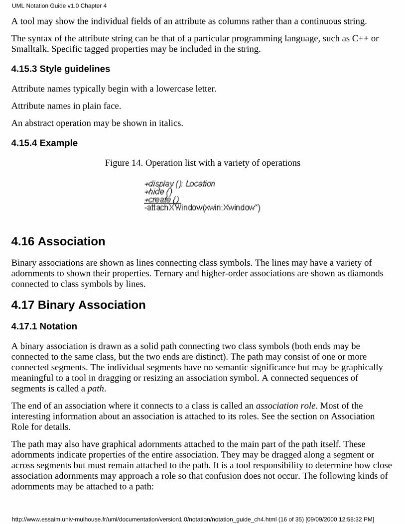
4.15.4 Example
Figure 14. Operation list with a variety of operations
4.16 Association
Binary associations are shown as lines connecting class symbols. The lines may have a variety ofadornments to shown their properties. Ternary and higher-order associations are shown as diamondsconnected to class symbols by lines.
4.17 Binary Association
4.17.1 Notation
A binary association is drawn as a solid path connecting two class symbols (both ends may beconnected to the same class, but the two ends are distinct). The path may consist of one or moreconnected segments. The individual segments have no semantic significance but may be graphicallymeaningful to a tool in dragging or resizing an association symbol. A connected sequences ofsegments is called a path.
The end of an association where it connects to a class is called an association role. Most of theinteresting information about an association is attached to its roles. See the section on AssociationRole for details.
The path may also have graphical adornments attached to the main part of the path itself. Theseadornments indicate properties of the entire association. They may be dragged along a segment oracross segments but must remain attached to the path. It is a tool responsibility to determine how closeassociation adornments may approach a role so that confusion does not occur. The following kinds ofadornments may be attached to a path:
UML Notation Guide v1.0 Chapter 4
http://www.essaim.univ-mulhouse.fr/uml/documentation/version1.0/notation/notation_guide_ch4.html (16 of 35) [09/09/2000 12:58:32 PM]
association name
Designates the (optional) name of the association.
Shown as a name string near the path. The string may have an optional smallblack solid triangle in it; the point of the triangle indicates the direction inwhich to read the name. The name-direction arrow has no semanticssignificance; it is purely descriptive. The classes in the association areordered as indicated by the name-direction arrow. (Note that there is no needfor a name direction property on the association model; the ordering of theclasses within the association is the name direction. This convention workseven with n-ary associations.) A stereotype keyword within guillemets maybe placed above or in front of the association name. A property string may beplaced after or below the association name.
association class symbol
Designates an association that has class-like properties, such as attributes,operations, and other associations. This is present if and only if theassociation is an association class.
Shown as a class symbol attached to the association path by a dashed line.
The association path and the association class symbol represent the sameunderlying model element which has a single name. The name may beplaced on the path, in the class symbol, or on both (but they must be thesame name).
Logically the association class and the association are the same semanticentity, but they are graphically distinct. The association class symbol can bedragged away from the line but the dotted line must remain attached to boththe path and the class symbol.
4.17.2 Presentation options
When two paths cross, the crossing may optionally be shown with a small semicircular jog to indicatethat the paths do not intersect (as in electrical circuit diagrams).
4.17.3 Style guidelines
Lines may be drawn at any angle. One popular style is to draw straight paths between icons wheneverpossible. Another popular style is to have all lines be horizontal or vertical (orthogonal grid), usingmultiple segments to compose paths when necessary. In any case the user should be consistent.
4.17.4 Options
Or-association. An or-constraint indicates a situation in which only one of several potentialassociations may be instantiated at one time for any single object. This is shown as a dashed lineconnecting two or more associations, all of which must have a class in common, with the constraint
UML Notation Guide v1.0 Chapter 4
http://www.essaim.univ-mulhouse.fr/uml/documentation/version1.0/notation/notation_guide_ch4.html (17 of 35) [09/09/2000 12:58:32 PM]
string ''{or}'' labeling the dashed line. Any instance of the class may only participate in at most one ofthe associations at one time. (This is simply a particular use of the constraint notation.)
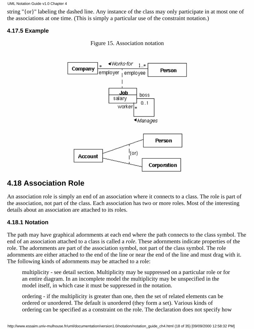
4.17.5 Example
Figure 15. Association notation
4.18 Association Role
An association role is simply an end of an association where it connects to a class. The role is part ofthe association, not part of the class. Each association has two or more roles. Most of the interestingdetails about an association are attached to its roles.
4.18.1 Notation
The path may have graphical adornments at each end where the path connects to the class symbol. Theend of an association attached to a class is called a role. These adornments indicate properties of therole. The adornments are part of the association symbol, not part of the class symbol. The roleadornments are either attached to the end of the line or near the end of the line and must drag with it.The following kinds of adornments may be attached to a role:
multiplicity - see detail section. Multiplicity may be suppressed on a particular role or foran entire diagram. In an incomplete model the multiplicity may be unspecified in themodel itself, in which case it must be suppressed in the notation.
ordering - if the multiplicity is greater than one, then the set of related elements can beordered or unordered. The default is unordered (they form a set). Various kinds ofordering can be specified as a constraint on the role. The declaration does not specify how
UML Notation Guide v1.0 Chapter 4
http://www.essaim.univ-mulhouse.fr/uml/documentation/version1.0/notation/notation_guide_ch4.html (18 of 35) [09/09/2000 12:58:32 PM]
the ordering is established or maintained; operations that insert new elements must makeprovision for specifying their position either implicitly (such as at the end) or explicitly.Possible values include:
unordered -- the elements form an unordered set. This is the default and neednot be shown explicitly.
ordered -- the elements are ordered into a list. This generic specificationincludes all kinds of ordering. This may be specified by a keywordconstraint: ''{ordered}''.
An ordered relationship may be implemented in various ways but this is normallyspecified as a language-specified code generation property to select a particularimplementation.
At implementation level, sorting may also be specified. It does not add new semanticinformation but it expresses a design decision:
sorted -- the elements are sorted based on their internal values. The actualsorting rule is best specified as a separate constraint.
qualifier - see detail section. Qualifier is optional but not suppressible.
navigability
An arrow may be attached to the end of the path to indicate that navigation issupported toward the class attached to the arrow. Arrows may be attached tozero, one, or two ends of the path. In principle arrows could be shownwhenever navigation is supported in a given direction. In practice it issometimes convenient to suppress some of the arrows and just showexceptional situations. Here are some options on showing navigation arrows:
Presentation option 1: Show all arrows. The absence of an arrow indicatesnavigation is not supported.
Presentation option 2: Suppress all arrows. No inference can be drawn aboutnavigation. This is similar to any situation in which information issuppressed from a view.
Presentation options 3: Suppress arrows for associations with navigability inboth directions; show arrows only for associations with one-waynavigability. In this case the two-way navigability cannot be distinguishedfrom no-way navigation, but the latter case is normally rare or nonexistent inpractice. This is yet another example of a situation in which someinformation is suppressed from a view.
aggregation indicator
A hollow diamond is attached to the end of the path to indicate aggregation.The diamond may not be attached to both ends of a line, but it need not be
UML Notation Guide v1.0 Chapter 4
http://www.essaim.univ-mulhouse.fr/uml/documentation/version1.0/notation/notation_guide_ch4.html (19 of 35) [09/09/2000 12:58:32 PM]
present at all. The diamond is attached to the class that is the aggregate. Theaggregation is optional but not suppressible.
If the diamond is filled, then it signifies the strong form of aggregationknown as composition.
rolename
A name string near the end of the path. It indicates the role played by theclass attached to end of the path near the rolename. The rolename is optionalbut not suppressible.
Other properties can be specified for association roles but there is no graphical syntax for them. Tospecify such properties use the constraint syntax near the end of the association path (a text string inbraces). Examples of such other properties include mutability.
4.18.2 Presentation options
If there are two or more aggregations to the same aggregate, they may be drawn as a tree by mergingthe aggregation end into a single segment. This requires that all of the adornments on the aggregationends be consistent. This is purely a presentation option; there are no additional semantics to it.
4.18.3 Style guidelines
If there are multiple adornments on a single role, they are presented in the following order, readingfrom the end of the path attached to the class toward the bulk of the path:
qualifier
aggregation symbol
navigation arrow
Rolenames and multiplicity should be placed near the end of the path so that they are not confusedwith a different association. They may be placed on either side of the line. It is tempting to specify thatthey will always be placed on a given side of the line (clockwise or counterclockwise) but this issometimes overridden by the need for clarity in a crowded layout. A rolename and a multiplicity maybe placed on opposite sides of the same role, or they may be placed together (for example, ''*employee'').
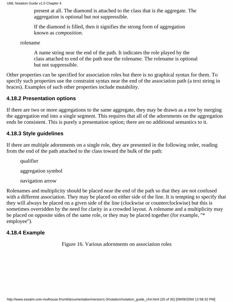
4.18.4 Example
Figure 16. Various adornments on association roles
UML Notation Guide v1.0 Chapter 4
http://www.essaim.univ-mulhouse.fr/uml/documentation/version1.0/notation/notation_guide_ch4.html (20 of 35) [09/09/2000 12:58:32 PM]
4.19 Multiplicity
A multiplicity string specifies the range of allowable cardinalities that a set may assume. Multiplicityspecifications may be given for roles within associations, parts within composites, repetitions, andother purposes. Essentially a multiplicity is a subset of the nonnegative open integers.
4.19.1 Notation
A multiplicity specification is shown as a text string comprising a comma-separated sequence ofinteger intervals, where an interval represents a (possibly infinite) range of integers, in the format:
lower-bound .. upper-bound
where lower-bound and upper-bound are literal integer values, specifying the closed (inclusive) rangeof integers from the lower bound to the upper bound. In addition, the star character (*) may be used forthe upper bound, denoting an unlimited upper bound. In a parameterized context (such as a template)the bounds could be expressions but they must evaluate to literal integer values for any actual use.Unbound expressions that do not evaluate to literal integer values are not permitted.
If a single integer value is specified, then the integer range contains the single integer value.
If the multiplicity specification comprises a single star (*), then it denotes the unlimited nonnegativeinteger range, that is, it is equivalent to *..* = 0..* (zero or more).
4.19.2 Style guidelines
Intervals should preferably be monotonically increasing. For example, ''1..3,7,10'' is preferable to''7,10,1..3''.
Two contiguous intervals should be combined into a single interval. For example, ''0..1'' is preferableto ''0,1''.
4.19.3 Example
0..1
1
UML Notation Guide v1.0 Chapter 4
http://www.essaim.univ-mulhouse.fr/uml/documentation/version1.0/notation/notation_guide_ch4.html (21 of 35) [09/09/2000 12:58:32 PM]
0..*
*
1..*
1..6
1..3,7..10,15,19..*
4.20 Qualifier
A qualifier is an association attribute or tuple of attributes whose values serve to partition the set ofobjects associated with an object across an association.
4.20.1 Notation
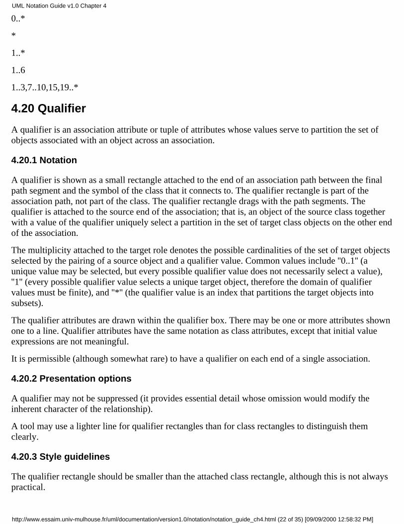
A qualifier is shown as a small rectangle attached to the end of an association path between the finalpath segment and the symbol of the class that it connects to. The qualifier rectangle is part of theassociation path, not part of the class. The qualifier rectangle drags with the path segments. Thequalifier is attached to the source end of the association; that is, an object of the source class togetherwith a value of the qualifier uniquely select a partition in the set of target class objects on the other endof the association.
The multiplicity attached to the target role denotes the possible cardinalities of the set of target objectsselected by the pairing of a source object and a qualifier value. Common values include ''0..1'' (aunique value may be selected, but every possible qualifier value does not necessarily select a value),''1'' (every possible qualifier value selects a unique target object, therefore the domain of qualifiervalues must be finite), and ''*'' (the qualifier value is an index that partitions the target objects intosubsets).
The qualifier attributes are drawn within the qualifier box. There may be one or more attributes shownone to a line. Qualifier attributes have the same notation as class attributes, except that initial valueexpressions are not meaningful.
It is permissible (although somewhat rare) to have a qualifier on each end of a single association.
4.20.2 Presentation options
A qualifier may not be suppressed (it provides essential detail whose omission would modify theinherent character of the relationship).
A tool may use a lighter line for qualifier rectangles than for class rectangles to distinguish themclearly.
4.20.3 Style guidelines
The qualifier rectangle should be smaller than the attached class rectangle, although this is not alwayspractical.
UML Notation Guide v1.0 Chapter 4
http://www.essaim.univ-mulhouse.fr/uml/documentation/version1.0/notation/notation_guide_ch4.html (22 of 35) [09/09/2000 12:58:32 PM]
4.20.4 Example
Figure 17. Qualified associations
4.21 Association Class
An association class is an association that also has class properties (or a class that has associationproperties). Even though it is drawn as an association and a class, it is really just a single modelelement.
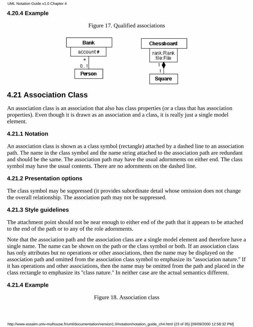
4.21.1 Notation
An association class is shown as a class symbol (rectangle) attached by a dashed line to an associationpath. The name in the class symbol and the name string attached to the association path are redundantand should be the same. The association path may have the usual adornments on either end. The classsymbol may have the usual contents. There are no adornments on the dashed line.
4.21.2 Presentation options
The class symbol may be suppressed (it provides subordinate detail whose omission does not changethe overall relationship. The association path may not be suppressed.
4.21.3 Style guidelines
The attachment point should not be near enough to either end of the path that it appears to be attachedto the end of the path or to any of the role adornments.
Note that the association path and the association class are a single model element and therefore have asingle name. The name can be shown on the path or the class symbol or both. If an association classhas only attributes but no operations or other associations, then the name may be displayed on theassociation path and omitted from the association class symbol to emphasize its ''association nature.'' Ifit has operations and other associations, then the name may be omitted from the path and placed in theclass rectangle to emphasize its ''class nature.'' In neither case are the actual semantics different.
4.21.4 Example
Figure 18. Association class
UML Notation Guide v1.0 Chapter 4
http://www.essaim.univ-mulhouse.fr/uml/documentation/version1.0/notation/notation_guide_ch4.html (23 of 35) [09/09/2000 12:58:32 PM]
4.22 N-ary association
4.22.1 Semantics
An n-ary association is an association among 3 or more classes (a single class may appear more thanonce). Each instance of the association is an n-tuple of values from the respective classes. A binaryassociation is a special case with its own notation.
Multiplicity for n-ary associations may be specified but is less obvious than binary multiplicity. Themultiplicity on a role represents the potential number of instance tuples in the association when theother N-1 values are fixed.
An n-ary association may not contain the aggregation marker on any role.
4.22.2 Notation
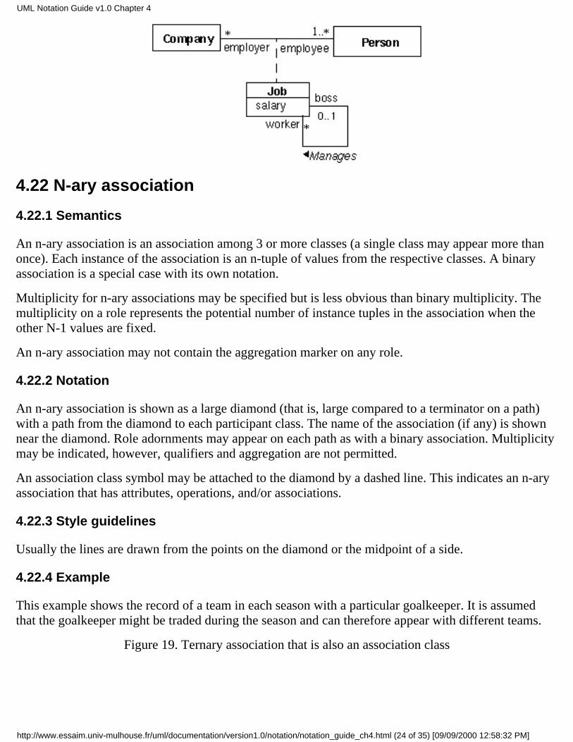
An n-ary association is shown as a large diamond (that is, large compared to a terminator on a path)with a path from the diamond to each participant class. The name of the association (if any) is shownnear the diamond. Role adornments may appear on each path as with a binary association. Multiplicitymay be indicated, however, qualifiers and aggregation are not permitted.
An association class symbol may be attached to the diamond by a dashed line. This indicates an n-aryassociation that has attributes, operations, and/or associations.
4.22.3 Style guidelines
Usually the lines are drawn from the points on the diamond or the midpoint of a side.
4.22.4 Example
This example shows the record of a team in each season with a particular goalkeeper. It is assumedthat the goalkeeper might be traded during the season and can therefore appear with different teams.
Figure 19. Ternary association that is also an association class
UML Notation Guide v1.0 Chapter 4
http://www.essaim.univ-mulhouse.fr/uml/documentation/version1.0/notation/notation_guide_ch4.html (24 of 35) [09/09/2000 12:58:32 PM]
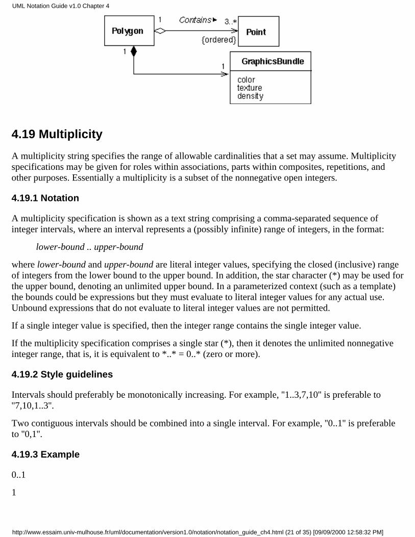
4.23 Composition
Composition is a form of aggregation with strong ownership and coincident lifetime of part with thewhole. The multiplicity of the aggregate end may not exceed one (it is unshared). The aggregation isunchangeable (once established the links may not be changed). Parts with multiplicity > 1 may becreated after the aggregate itself but once created they live and die with it. Such parts can also beexplicitly removed before the death of the aggregate.
Composition may be shown by a solid filled diamond as an association role adornment. AlternatelyUML provides a graphically-nested form that is more convenient for showing composition in manycases.
4.23.1 Semantics
Within a composite additional associations can be defined that are not meaningful within the system ingeneral. These represent patterns of connection that are meaningful only within the context of thecomposite. Such associations can be thought of as generating quasiclasses (or qua-types as Bock andOdell call them) that are specializations of the general classes; the specializations are defined onlyinside the composite. In actual practice it often happens that one of the classes in the association doesnot know about the association or the other class, so that the implementation need not actually use thequa-class.
The entire system may be thought of as an implicit composite, so that any multiplicity specificationswithin top-level classes restrict the cardinality of the classes in a particular execution; Embley'ssingleton classes can be seen in that light.
4.23.2 Notation
UML Notation Guide v1.0 Chapter 4
http://www.essaim.univ-mulhouse.fr/uml/documentation/version1.0/notation/notation_guide_ch4.html (25 of 35) [09/09/2000 12:58:32 PM]
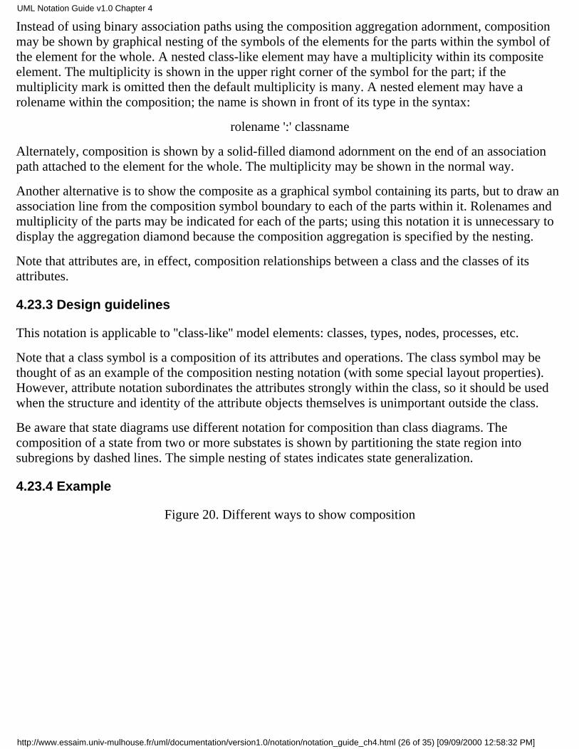
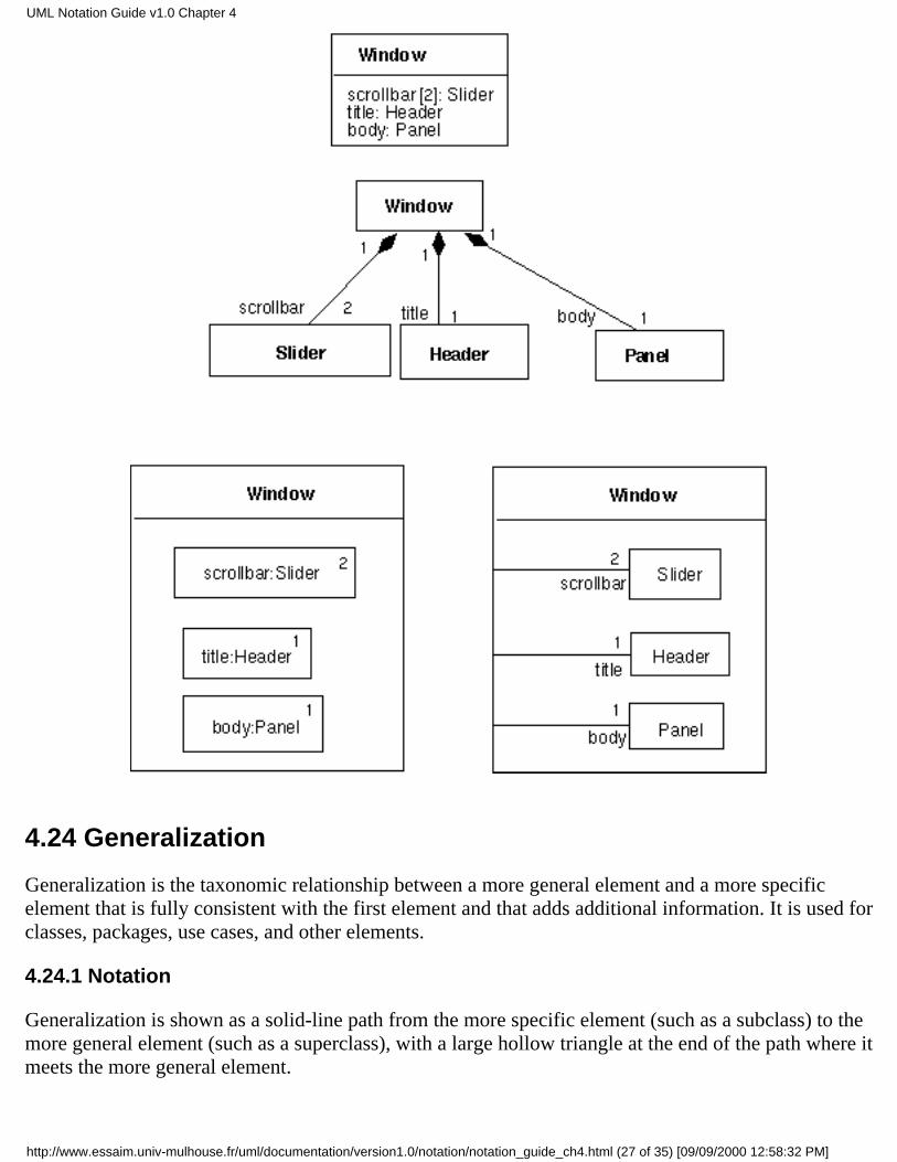
Instead of using binary association paths using the composition aggregation adornment, compositionmay be shown by graphical nesting of the symbols of the elements for the parts within the symbol ofthe element for the whole. A nested class-like element may have a multiplicity within its compositeelement. The multiplicity is shown in the upper right corner of the symbol for the part; if themultiplicity mark is omitted then the default multiplicity is many. A nested element may have arolename within the composition; the name is shown in front of its type in the syntax:
rolename ':' classname
Alternately, composition is shown by a solid-filled diamond adornment on the end of an associationpath attached to the element for the whole. The multiplicity may be shown in the normal way.
Another alternative is to show the composite as a graphical symbol containing its parts, but to draw anassociation line from the composition symbol boundary to each of the parts within it. Rolenames andmultiplicity of the parts may be indicated for each of the parts; using this notation it is unnecessary todisplay the aggregation diamond because the composition aggregation is specified by the nesting.
Note that attributes are, in effect, composition relationships between a class and the classes of itsattributes.
4.23.3 Design guidelines
This notation is applicable to ''class-like'' model elements: classes, types, nodes, processes, etc.
Note that a class symbol is a composition of its attributes and operations. The class symbol may bethought of as an example of the composition nesting notation (with some special layout properties).However, attribute notation subordinates the attributes strongly within the class, so it should be usedwhen the structure and identity of the attribute objects themselves is unimportant outside the class.
Be aware that state diagrams use different notation for composition than class diagrams. Thecomposition of a state from two or more substates is shown by partitioning the state region intosubregions by dashed lines. The simple nesting of states indicates state generalization.
4.23.4 Example
Figure 20. Different ways to show composition
UML Notation Guide v1.0 Chapter 4
http://www.essaim.univ-mulhouse.fr/uml/documentation/version1.0/notation/notation_guide_ch4.html (26 of 35) [09/09/2000 12:58:32 PM]
4.24 Generalization
Generalization is the taxonomic relationship between a more general element and a more specificelement that is fully consistent with the first element and that adds additional information. It is used forclasses, packages, use cases, and other elements.
4.24.1 Notation
Generalization is shown as a solid-line path from the more specific element (such as a subclass) to themore general element (such as a superclass), with a large hollow triangle at the end of the path where itmeets the more general element.
UML Notation Guide v1.0 Chapter 4
http://www.essaim.univ-mulhouse.fr/uml/documentation/version1.0/notation/notation_guide_ch4.html (27 of 35) [09/09/2000 12:58:32 PM]

A generalization path may have a text label in the following format:
discriminator : powertype
where discriminator is the name of a partition of the subtypes of the supertype. Thesubtype is declared to be in the given partition;
where powertype is the name of a type whose instances are subtypes of another type,namely the subtypes whose paths bear the powertype name. If a type symbol with thesame name appears in the model, it designates the same type; it should be shown with thestereotype «powertype». For example, TreeSpecies is a powertype on the Tree type;consequently instances of TreeSpecies (such as Oak or Birch) are also subtypes of Tree.
Either the discriminator, or the colon and powertype, or both may be omitted.
Note that the word type also includes both types and classes.
4.24.2 Presentation options
A group of generalization paths for a given superclass may be shown as a tree with a shared segment(including triangle) to the superclass, branching into multiple paths to each subclass.
If a text label is placed on a generalization triangle shared by several generalization paths tosubclasses, the label applies to all of the paths. In other words, all of the subclasses share the givenproperties.
4.24.3 Details
The existence of additional subclasses in the model that are not shown on a particular diagram may beshown using an ellipsis (. . .) in place of a subclass. (Note: this does not indicate that additional classesmay be added in the future. It indicates that additional classes exist right now but are not being seen.)
Predefined constraints may be used to indicate semantic constraints among the subclasses. Acomma-separated list of keywords is placed in braces either near the shared triangle (if several pathsshare a single triangle) or else near a dotted line that crosses all of the generalization lines involved.The following keywords (among others) may be used:
overlapping
disjoint
complete
incomplete
4.24.4 Semantics
The following constraints are predefined:
overlapping A descendent may be descended from more than one of the subclasses.
UML Notation Guide v1.0 Chapter 4
http://www.essaim.univ-mulhouse.fr/uml/documentation/version1.0/notation/notation_guide_ch4.html (28 of 35) [09/09/2000 12:58:32 PM]
disjoint A descendent may not be descended from more than one of the subclasses.
complete All subclasses have been specified (whether or not shown). No additionalsubclasses are expected.
incomplete Some subclasses have been specified but the list is known to be incomplete.There are additional subclasses that are not yet in the model. The is a statement about themodel itself. Note that this is not the same as the ellipsis, which states that additionalsubclasses exist in the model but are not shown on the current diagram.
The discriminator must be unique among the attributes and association roles of the given superclass.Multiple occurrences of the same discriminator name are permitted and indicate that the subclassesbelong to the same partition.
Semantic variation points
There are different possible ways to interpret the semantics of generalization (as with otherconstructs). Although there is a standard UML interpretation consistent with the operation of the majorobject-oriented languages, there are purposes and languages that require a different interpretation.Different semantics can be permitted by identifying semantic variation points and giving them names,so that different users and tools could understand the variation being used (it is not assumed that alltools will support this concepts). These are some semantic variations applicable to generalization:
Multiple inheritance. Whether a class may have more than one superclass.
Multiple classification. Whether an object may belong directly to more than one class.
Dynamic classification. Whether an object may change class during execution.
The ordinary UML semantics assumes multiple inheritance, no multiple classification, and no dynamicclassification, but most parts of the semantics and notation are not affected if these assumptions arechange.
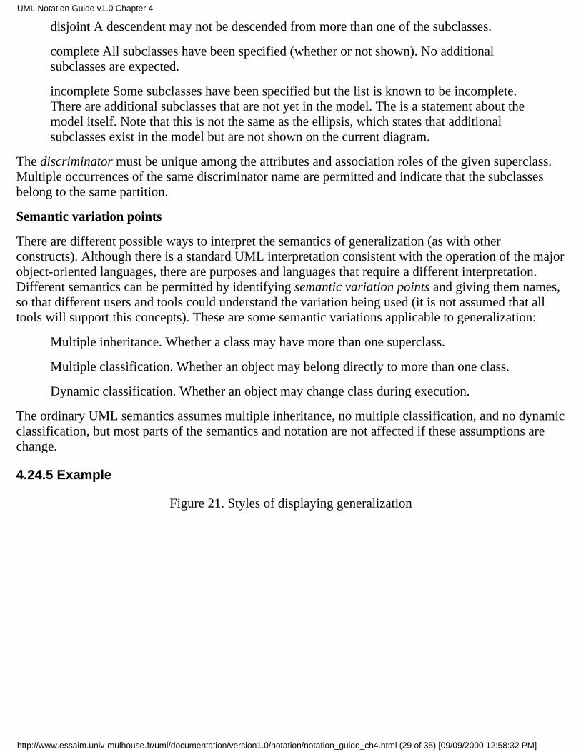
4.24.5 Example
Figure 21. Styles of displaying generalization
UML Notation Guide v1.0 Chapter 4
http://www.essaim.univ-mulhouse.fr/uml/documentation/version1.0/notation/notation_guide_ch4.html (29 of 35) [09/09/2000 12:58:32 PM]
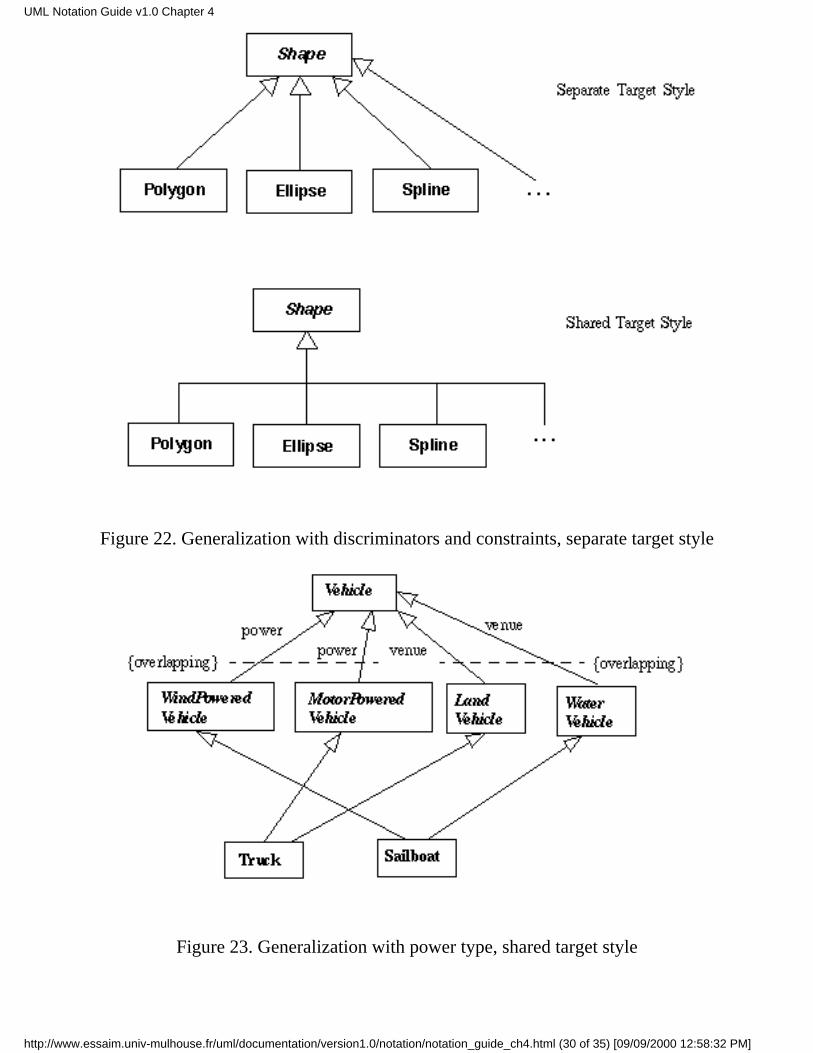
Figure 22. Generalization with discriminators and constraints, separate target style
Figure 23. Generalization with power type, shared target style
UML Notation Guide v1.0 Chapter 4
http://www.essaim.univ-mulhouse.fr/uml/documentation/version1.0/notation/notation_guide_ch4.html (30 of 35) [09/09/2000 12:58:32 PM]
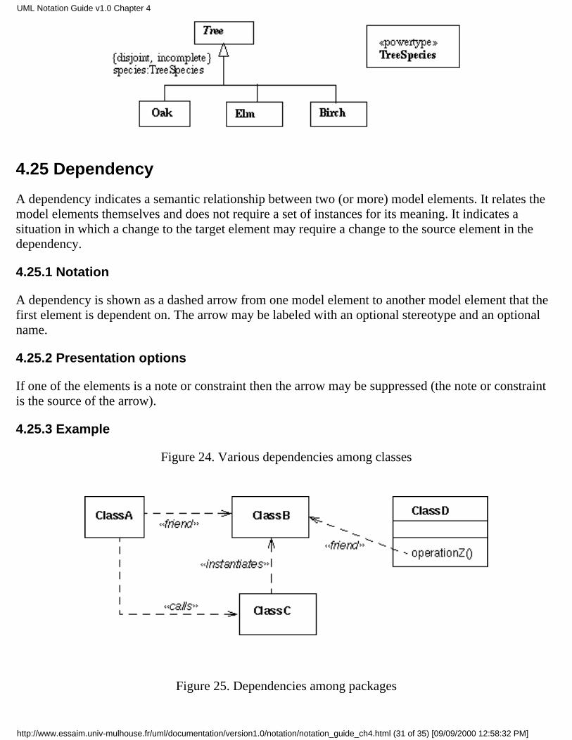
4.25 Dependency
A dependency indicates a semantic relationship between two (or more) model elements. It relates themodel elements themselves and does not require a set of instances for its meaning. It indicates asituation in which a change to the target element may require a change to the source element in thedependency.
4.25.1 Notation
A dependency is shown as a dashed arrow from one model element to another model element that thefirst element is dependent on. The arrow may be labeled with an optional stereotype and an optionalname.
4.25.2 Presentation options
If one of the elements is a note or constraint then the arrow may be suppressed (the note or constraintis the source of the arrow).
4.25.3 Example
Figure 24. Various dependencies among classes
Figure 25. Dependencies among packages
UML Notation Guide v1.0 Chapter 4
http://www.essaim.univ-mulhouse.fr/uml/documentation/version1.0/notation/notation_guide_ch4.html (31 of 35) [09/09/2000 12:58:32 PM]
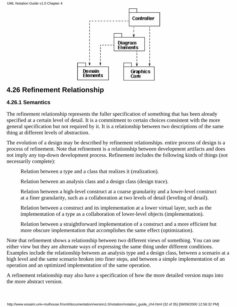
4.26 Refinement Relationship
4.26.1 Semantics
The refinement relationship represents the fuller specification of something that has been alreadyspecified at a certain level of detail. It is a commitment to certain choices consistent with the moregeneral specification but not required by it. It is a relationship between two descriptions of the samething at different levels of abstraction.
The evolution of a design may be described by refinement relationships. entire process of design is aprocess of refinement. Note that refinement is a relationship between development artifacts and doesnot imply any top-down development process. Refinement includes the following kinds of things (notnecessarily complete):
Relation between a type and a class that realizes it (realization).
Relation between an analysis class and a design class (design trace).
Relation between a high-level construct at a coarse granularity and a lower-level constructat a finer granularity, such as a collaboration at two levels of detail (leveling of detail).
Relation between a construct and its implementation at a lower virtual layer, such as theimplementation of a type as a collaboration of lower-level objects (implementation).
Relation between a straightforward implementation of a construct and a more efficient butmore obscure implementation that accomplishes the same effect (optimization).
Note that refinement shows a relationship between two different views of something. You can useeither view but they are alternate ways of expressing the same thing under different conditions.Examples include the relationship between an analysis type and a design class, between a scenario at ahigh level and the same scenario broken into finer steps, and between a simple implementation of anoperation and an optimized implementation of the same operation.
A refinement relationship may also have a specification of how the more detailed version maps intothe more abstract version.
UML Notation Guide v1.0 Chapter 4
http://www.essaim.univ-mulhouse.fr/uml/documentation/version1.0/notation/notation_guide_ch4.html (32 of 35) [09/09/2000 12:58:32 PM]

4.26.2 Notation
Refinement may be shown as a dashed generalization symbol, that is, a dashed line with a closedhollow triangular arrowhead on the end connected to more general element. A stereotype may beattached to specify a particular kind of refinement. A note may be attached to the line stating themapping from the more specific form to the more general form.
Refinement within a given model can be shown as a dependency with the stereotype «refines» or oneof its more specific forms, such as «implements». Refinement between models may be modeled as aninvisible hyperlink supported by a dynamic tool. The refinement relationship may have a mappingattached to it; the mapping will normally be reached via an invisible hyperlink from the relationshippath.
4.26.3 Example
Figure 26. Refinement
4.27 Derived Element
A derived element is one that can be computed from another one, but that is shown for clarity or that isincluded for design purposes even though it adds no semantic information.
4.27.1 Notation
A derived element is shown by placing a slash (/) in front of the name of the derived element, such asan attribute or a rolename.
UML Notation Guide v1.0 Chapter 4
http://www.essaim.univ-mulhouse.fr/uml/documentation/version1.0/notation/notation_guide_ch4.html (33 of 35) [09/09/2000 12:58:32 PM]

4.27.2 Style guidelines
The details of computing a derived element can be specified by a dependency with the stereotype«derived». Usually it is convenient in the notation to suppress the dependency arrow and simply placea constraint string near the derived element, although the arrow can be included when it is helpful.
4.27.3 Example
Figure 27. Derived attribute and derived association
4.28 Navigation Expression
UML notation provides a small language for expressing navigation paths in class models.
4.28.1 Notation
These forms can be chained together. The leftmost element must be an expression for an object or a setof objects. The expressions are meant to work on sets of values when applicable.
set '.' selector
the selector is the name of an attribute in the objects of the set or the name of a role of thetarget end of a link attached to the objects in the set. The result is the value of the attributeor the related object(s). The result is a value or a set of values depending on themultiplicity of the set and the association.
set '.' '~' selector
UML Notation Guide v1.0 Chapter 4
http://www.essaim.univ-mulhouse.fr/uml/documentation/version1.0/notation/notation_guide_ch4.html (34 of 35) [09/09/2000 12:58:32 PM]
the selector is the name of a role on the source end of an association attached to the set ofobjects. The result is the object(s) attached to the other side. This represents an inverserelationships, that is, the use of the rolename in the "wrong way."
set '[' boolean-expression ']'
the boolean-expression is written in terms of objects within the set and values accessiblefrom them. The result is the subset of objects for which the boolean expression is true.
set '.' selector '[' qualifier-value ']'
the selector designates a qualified association that qualifies the set. The qualifier-value isa value for the qualifier attribute. The result is the related object selected by the qualifier.Note that this syntax is applicable to array indexing as a form of qualification.
4.28.2 Example
flight.pilot.training_hours > flight.plane.minimum_hours
company.employee [title = "Manager" and count (employee) > 10]
| Previous | Next | Notation TOC | getRational! |
Copyright © 1997 by Rational Software Corporation. All rights reserved.
UML Notation Guide v1.0 Chapter 4
http://www.essaim.univ-mulhouse.fr/uml/documentation/version1.0/notation/notation_guide_ch4.html (35 of 35) [09/09/2000 12:58:32 PM]