Embed Size (px)
Citation preview

NSF/ANSI 55 – 2002
Ultraviolet microbiological water treatment systems
NSF International Standard/ American National Standard
NSF
/AN
SI 5
5 –
2002

NSF International, an independent, not-for-profit, non-governmental organization, is dedicated to being the leading global supplier of public health and safety-based risk management services serving the in-terests of all stakeholders.
This Standard is subject to revision. Contact NSF to confirm this revision is current.
Users of this Standard may request clarifications and in-
terpretations, or propose revisions by contacting:
Chair, Joint Committee on Drinking Water Treatment Units c/o NSF International
789 North Dixboro Road, P.O. Box 130140 Ann Arbor, Michigan 48113-0140 USA
Phone: (734) 769-8010 Telex: 753215 NSF INTL FAX: (734) 769-0109 E-mail: [email protected]
Web: http://www.nsf.org
NSF/ANSI 55 – 2002
i
NSF International Standard/ American National Standard
for Drinking Water Treatment Units –
Ultraviolet microbiological water treatment systems
Standard Developer NSF International Adopted January 29, 2002 NSF International Designated as an ANSI Standard January 29, 2002 American National Standards Institute

ii
Prepared by The NSF Joint Committee on Drinking Water Treatment Units Recommended for Adoption by The NSF Council of Public Health Consultants Adopted by The NSF Board of Directors May 1991 Revised January 2000 Revised January 2002 Published by NSF International PO Box 130140, Ann Arbor, Michigan 48113-0140, USA For ordering copies or for making inquiries with regard to this Standard, please reference the designation “NSF/ANSI 55 – 2002.” Copyright 2002 NSF International Previous edition © 2000, 1991 Unless otherwise specified, no part of this publication may be reproduced or utilized in any form or by any means, electronic or mechanical, including photocopying and microfilm, without permission in writing from NSF International. Printed in the United States of America.

iii
Disclaimers1 NSF International (NSF), in performing its functions in accordance with its objectives, does not assume or undertake to discharge any responsibility of the manufacturer or any other party. The opinions and find-ings of NSF represent its professional judgment. NSF shall not be responsible to anyone for the use of or reliance upon this Standard by anyone. NSF shall not incur any obligation or liability for damages, includ-ing consequential damages, arising out of or in connection with the use, interpretation of, or reliance upon this Standard. NSF Standards provide basic criteria to promote sanitation and protection of the public health. Provisions for mechanical and electrical safety have not been included in this Standard because governmental agencies or other national standards-setting organizations provide safety requirements. Participation in NSF’s Standards development activities by regulatory agency representatives (federal, local, state) shall not constitute their agency's endorsement of NSF or any of its Standards. Preference is given to the use of performance criteria measurable by examination or testing in NSF Stan-dards development when such performance criteria may reasonably be used in lieu of design, materials, or construction criteria. The illustrations, if provided, are intended to assist in understanding their adjacent standard requirements. However, the illustrations may not include all requirements for a specific product or unit, nor do they show the only method of fabricating such arrangements. Such partial drawings shall not be used to justify im-proper or incomplete design and construction. Unless otherwise referenced, the annexes are not considered an integral part of NSF Standards. The an-nexes are provided as general guidelines to the manufacturer, regulatory agency, user, or certifying or-ganization.
1 The information contained in this Disclaimer is not part of this American National Standard (ANS) and has not been processed in accordance with ANSI’s requirements for an ANS. As such, this Disclaimer may contain material that has not been subjected to public review or a consensus process. In addition, it does not contain requirements neces-sary for conformance to the Standard.

iv
This page is intentionally blank.

v
Contents Foreword ......................................................................................................................................................vii 1 General .................................................................................................................................................... 1
1.1 Purpose............................................................................................................................................ 1 1.2 Scope ............................................................................................................................................... 1 1.3 Variance from minimum requirements ............................................................................................. 1 1.4 Alternate materials ........................................................................................................................... 2
2 Normative references............................................................................................................................... 2 3 Definitions ................................................................................................................................................ 2 4 Materials................................................................................................................................................... 4
4.1 Materials in contact with drinking water ........................................................................................... 4 4.2 Materials evaluation ......................................................................................................................... 5
5 Design and construction .......................................................................................................................... 5
5.1 General............................................................................................................................................. 5 5.2 Working pressure ............................................................................................................................. 6 5.3 Performance indication .................................................................................................................... 6 5.4 Elements .......................................................................................................................................... 6 5.5 Flow control ...................................................................................................................................... 6 5.6 Waste connections........................................................................................................................... 6 5.7 Product water dispensing outlets ..................................................................................................... 6 5.8 Hazards............................................................................................................................................ 6 5.9 Lamp operation indication ................................................................................................................ 6 5.10 Electrical requirements..................................................................................................................... 6 5.11 Lamp replacement ........................................................................................................................... 6 5.12 Maintenance..................................................................................................................................... 6 5.13 Temperature resistance ................................................................................................................... 7 5.14 Corrodible materials ......................................................................................................................... 7 5.15 Gaskets, o-rings, shaft seals, and packing materials ...................................................................... 7 5.16 Dissimilar metals .............................................................................................................................. 7 5.17 Insulating fittings .............................................................................................................................. 7 5.18 Plastics ............................................................................................................................................. 7 5.19 Welding ............................................................................................................................................ 7
6 Performance ............................................................................................................................................ 7
6.1 General............................................................................................................................................. 7 6.2 Structural integrity ............................................................................................................................ 7 6.3 Microbiological performance ............................................................................................................ 9
7 Instruction and information..................................................................................................................... 15
7.1 Installation, operation, and maintenance instruction...................................................................... 15 7.2 Data plate....................................................................................................................................... 16 7.3 Replacement components ............................................................................................................. 17 7.4 Performance data sheet................................................................................................................. 17
Figures Figure 1 – Structural test apparatus....................................................................................................... 20 Figure 2 – Collimated beam apparatus .................................................................................................. 21 Figure 3 – Example test apparatus ....................................................................................................... 22
vi
Tables Table 1 – Extraction testing parameters................................................................................................. 23 Table 2 – Formulation dependent extraction testing parameters ........................................................... 25 Table 3 – Materials listed in U.S. Code of Federal Regulations,............................................................ 27 Table 4 – Non-specific extraction testing parameters ............................................................................ 28 Table 5 – Structural integrity testing requirements ................................................................................. 29 Table 6 – Sampling for disinfection performance ................................................................................... 30
Annexes A Ultraviolet water treatment systems microbial reduction .......................................................................A1
A.1 Summary.....................................................................................................................................A1 A.2 Equipment...................................................................................................................................A1 A.3 Microorganisms...........................................................................................................................A1 A.4 Supplies ......................................................................................................................................A1 A.5 Reagents.....................................................................................................................................A1 A.6 Safety precautions and hazards .................................................................................................A2 A.7 Growth medium...........................................................................................................................A2 A.8 Culture of challenge organisms ..................................................................................................A3 A.9 Drinking water treatment unit challenge organism suspension preparation...............................A5 A.10 Analysis of influent and effluent samples ...................................................................................A5 A.11 Challenge verification .................................................................................................................A6
B Key elements of a certification program for drinking water treatment systems and components .........B1
B.1 Marking the product .......................................................................................................................B1 B.2 Listing certified companies.............................................................................................................B1 B.3 Annual audits .................................................................................................................................B1 B.4 Testing............................................................................................................................................B1 B.5 Toxicological evaluation of materials formulations ........................................................................B1 B.6 Corrective action ............................................................................................................................B2 B.7 Enforcement...................................................................................................................................B2 B.8 Administrative review .....................................................................................................................B2 B.9 Appeals ..........................................................................................................................................B2 B.10 Complaints .....................................................................................................................................B2 B.11 Advertising .....................................................................................................................................B2 B.12 Records..........................................................................................................................................B2 B.13 Public notice...................................................................................................................................B2 B.14 Confidentiality.................................................................................................................................B2

vii
Foreword2 It is the purpose of this Standard to establish minimum requirements for the reduction of microorganisms using ultraviolet radiation (UV). UV water treatment systems covered by this Standard are intended for water that may be either microbiologically safe or microbiologically unsafe. This Standard also specifies the minimum product literature and labeling information that a manufacturer shall supply to authorized representatives and system owners, as well as the minimum service-related obligations that the manufac-turer shall extend to system owners. Systems covered by this Standard are in keeping with the Report of Task Force on Guide Standard and Protocol for Testing Microbiological Water Purifiers, April, 1987.3 It is recognized that the federal, state and local objectives are to provide safe water supplies without user treatment. However, many users are faced with the presence of contaminants of both aesthetic and health concern in their water supplies and need guidance as to the availability of tested and certified point-of-entry and point-of-use ultraviolet water treatment systems. This Standard will help to meet this need but cannot be expected to address claims beyond those covered in this Standard. Since it was not economically feasible to mount a routine testing program using all of the target microor-ganisms, e.g., bacteria, viruses, and protozoan cysts, an equivalent "disinfection" set of tests and re-quirements was developed for point-of-use and point-of-entry ultraviolet disinfection systems. A virus reduction of 4 log against a poliovirus and rotavirus challenge and a bacteriological reduction of 6 logs against a challenge of a coliform bacteria (Klebsiella terrigena) has been recommended by Schaub and an expert task force (1987).4 The technical and health protection problems (laboratory staff) and the inherent cost of establishing and maintaining a live virus test program preclude its routine application in a multipurpose standards testing laboratory. Consequently, an alternate means of assuring virus efficacy was developed. Survival data for poliovirus and rotavirus (Chang, 1985)5 show between a 3- to 4-log reduction in both poliovirus and rotavirus may be accomplished by a UV dosage of 30,000 µW-sec/cm2 while a greater than 6-log reduction of Escherichia coli may be projected. Additional data (Harris, 1986)6 shows a 5-log reduc-tion of poliovirus at 40,000 µw-sec/cm2. In NSF/ANSI 55 2000, a minimum UV dosage of 38,000 µW-sec/cm2 at the failsafe setpoint was set as an equivalent 4-log virus reduction requirement. To be consis-tent with International Standards, the minimum UV dose in NSF/ANSI 55 2002 has been changed to 40 mJ/cm2 (40,000 µw-sec/cm2) at the alarm set point. Prior to the late 1990’s it was thought ultraviolet light had limited cysticidal ability, which required informa-tion for the user as to the need for a prefilter complying with NSF/ANSI 53: Drinking water treatment units – Health effects for cyst reduction. Survival data for Cryptosporidium (Clancy, 2000)7 and Giardia (Craik, 2 The information contained in this Foreword is not part of this American National Standard (ANS) and has not been processed in accordance with ANSI’s requirements for an ANS. As such, this Foreword may contain material that has not been subjected to public review or a consensus process. In addition, it does not contain requirements necessary for conformance to the Standard. 3 Guide Standard and Protocol for Testing Microbiological Water Purifiers, Report of Task Force, submitted by Steven A. Schaub to the USEPA, April 1987. 4 Ibid., p. 7. 5 “UV Inactivation of Pathogenic and Indicator Microorganisms,” Chang, J.C., Johnson, J. Doald, et al. Journal of Applied Environmental Microbiology, Vol. 49, pp. 1361–1365, 1985. 6 “UV Inactivation of Selected Bacteria and Viruses With Photoreactivation of the Bacteria,” Harris, D. George, Ad-ams, Dean, et al., Water Resources, Vol. 21, pp. 687–692, 1986. 7 “Using UV to Inactivate Crypospordium,” Clancy, J. L., et al. Journal of American Water Works, Vol 92, Issue 9, pp. 97-104, 2000.

viii
2000)8 show minimum 3- to 4-log reduction in both Cryptosporidium and Giardia may be accomplished by a UV dosage of 10 mJ/cm2. Where drinking water is considered to be free of disease causing pathogenic organisms and has a turbid-ity level within acceptable drinking water standards, ultraviolet treatment may be useful for the supple-mental treatment of this drinking water. It would be suitable for the reduction of normally occurring micro-biological flora (non-spore forming heterotrophic bacteria) commonly found in drinking water. Survival data (Chang, 1985)9 show a greater than 2-log reduction of non-spore forming heterotrophic bacteria may be accomplished by an ultraviolet dosage of 16,000 µW-sec/cm2. The yeast organism Saccharomyces cerevisiae was chosen as the test challenge to allow for a reasonable influent concentration and an easily measured reduction in the effluent. Most vegetative bacteria including coliform species are too suscepti-ble to UV radiation at the dose range of 16,000 µW-sec/cm2 to allow for measurable testing. Water contact materials in Drinking Water Treatment Units listed under NSF/ANSI 42, 44, 53, 55, 58 and 62 are tested and evaluated under a separate protocol from NSF/ANSI 61 with criteria that were devel-oped specifically for the intended end use. NSF/ANSI 61 listing should not be additionally required for acceptance of these listed units for water contact application. This version of the Standard contains the following revisions:
– NSF/ANSI 55 covers two types of UV treatment systems: Class A systems are intended for the inactivation of pathogenic bacteria and viruses; Class B systems are intended for the reduction of nonpathogenic, nuisance organisms. This edition of the Standard increases the scope of Class A sys-tems claims to include Cryptosporidium and Giardia. In addition, Class A systems may make a gen-eral cyst claim when supplied with a device that has been tested against a NSF/ANSI Standard for cyst reduction/inactivation. – In order to verify systems claims, the Standard historically has used a “surrogate” organism to de-termine the UV dose applied based on log reduction curves. This edition of the Standard continues with that mode of testing, but the Class A challenge organism now is MS-2 Coliphage, not Bacillus subtilis. – A quality assurance/quality control section for the collimated beam and challenge organism (MS-2 Coliphage) was drafted (see 6.3.4.1). The intent of this section is to provide assurance that the propagation, harvest, and preparation of the challenge stock produce a homogenous, monodispersed suspension of the challenge organism prior to the suspension’s introduction to the UV system. – In step H of the challenge organism bioassay – dose response, the sampling requirement has been increased to three data points (see 6.3.1.3.1). – In step G of the microbiological test method for flow through systems, language has been added to clarify that five unit void volumes will pass through the unit before the sample is taken (see 6.3.2.7). – Section 4 has been editorially revised to clarify the intent of the materials evaluation testing pro-cedures. New language has been added to detail the follow-up actions when a contaminant’s advi-sory concentration is exceeded in the extractant water. A new health concern contaminant category, “Maximum Contaminant Concentration” (MCC), has been created. Current MDWL values, which are numbers set by a recognized regulatory agency, have been relocated under the MCC headings in Tables 1 and 2.
8 “Inactivation of Giardia Muris Cysts Using Medium-Pressure Ultraviolet Radiation in Filtered Drinking water,” Craik, S. A., et al. Water Resources, Vol. 34, No. 18, pp 4325-4332, 2000. 9 Ibid., p. 1362.
ix
– Pressure testing requirements and materials testing requirements are now consistent with the methods of other NSF Drinking Water Treatment Unit Standards. – Other revisions to the Standard not detailed above generally aim to further clarify the Standard’s intent or to be consistent with the stable of NSF DWTU Standards.
This Standard and the accompanying testing program will provide assurance to the user and the regula-tory officials that point-of-entry and point-of-use ultraviolet water treatment systems will perform, with proper operation and maintenance, in accordance with the claims made under the Standard. However, final acceptance of systems for any application covered under governmental regulation will be subject to the approval of the appropriate federal, state, and/or local regulatory agency having jurisdiction. This Standard was developed by the NSF Joint Committee on Drinking Water Treatment Units using the consensus process described by the American National Standards Institute. Suggestions for improvement of this Standard are welcome. Comments should be sent to Chair, Joint Committee on Drinking Water Treatment Units, c/o NSF International, Standards Department, PO Box 130140, Ann Arbor, Michigan 48113-0140, USA.

x
This page in intentionally blank.
1
© 2002 NSF NSF/ANSI 55 – 2002 NSF/ANSI Standard for Drinking Water Treatment Units –
Ultraviolet microbiological water treatment units 1 General 1.1 Purpose It is the purpose of this Standard to establish minimum requirements for the reduction of mi-croorganisms using ultraviolet radiation (UV). UV water treatment systems covered by this Standard are intended for water that may be either microbiologically safe or microbiologically unsafe. This Standard also specifies the mini-mum product literature and labeling information that a manufacturer shall supply to authorized representatives and system owners as well as the minimum service-related obligations that the manufacturer shall extend to system owners. 1.2 Scope This Standard covers ultraviolet microbiological water treatment systems and components for point-of-use and point-of-entry applications. Sys-tems are intended to be used under the follow-ing specific conditions. 1.2.1 Class A systems Class A point-of-entry and point-of-use systems covered by this Standard are designed to inacti-vate and/or remove microorganisms, including bacteria, viruses, Cryptosporidium oocysts, and Giardia cysts, from contaminated water. Sys-tems covered by this Standard are not intended for the treatment of water that has an obvious contamination or intentional source, such as raw sewage, nor are systems intended to convert wastewater to drinking water. The systems are intended to be installed on visually clear water (not colored, cloudy, or turbid). Class A systems not installed downstream of a
device tested for cyst reduction/inactivation in conformance with the appropriate NSF/ANSI Standard may claim Cryptosporidium oocysts and Giardia cysts only. Class A systems in-stalled downstream of a device tested for cyst reduction/inactivation in conformance with the appropriate NSF/ANSI standard may make a general cyst claim when used on untreated sur-face waters and/or ground water under the direct influence of surface water.
NOTE – Current data supports that Cryptosporid-ium oocysts and Giardia cysts are inactivated by ultraviolet treatment
1.2.2 Class B systems or components Class B point-of-entry and point-of-use systems covered by this Standard are designed for sup-plemental bactericidal treatment of disinfected public drinking water or other drinking water that has been tested and deemed acceptable for human consumption by the state or local health agency having jurisdiction. The system is de-signed to reduce normally occurring nonpatho-genic nuisance microorganisms only. The Class B system is not intended for the disinfection of microbiologically unsafe water and may not make individual or general cyst claims. Class B systems shall not make microbiological health effects claims. 1.3 Variance from minimum requirements Variations from the minimum requirements specified in 4, 5, 6 and 7 may be permitted pro-vided they give the system or component the same or greater resistance to corrosion, wear, and physical damage, or if they improve the general operation or performance of the system or component. Proposed variations shall be ac-cepted by the testing agency prior to use. Sys-

NSF/ANSI 55 – 2002 © 2002 NSF
2
tems with components or functions covered un-der existing NSF standards or criteria shall com-ply with those applicable requirements. 1.4 Alternate materials If specific materials are mentioned, other mate-rials that provide at least equal performance and sanitation shall be acceptable. 2 Normative references The following reference documents contain pro-visions that constitute requirements of this Stan-dard. At the time of publication, the indicated editions were valid. All documents are subject to revision, and it is the responsibility of the user of this specification to determine the applicability of the most recent editions of these documents. ANSI/NFPA 70, 1999, National Electric Code10
APHA, Standard Methods for the Examination of Water and Wastewater, twentieth edition11 NSF/ANSI 53 – 2001, Drinking water treatment units – Health effects NSF/ANSI 58 – 2001, Reverse osmosis drinking water treatment systems NSF/ANSI 61 – 2001, Drinking water system components – Health effects NSF/ANSI 62 – 1999, Drinking water distillation systems USEPA 600/479020, Methods for the Chemical Analysis of Water and Wastes, March 198312 USEPA 600/R94/111, Methods for the Determi-nation of Metals in Environmental Samples, Supplement 1, May 199412
10 National Fire Protection Association, 1 Battery-march Park, Quincy, MA 02269 11 American Public Health Association (APHA), 800 I Street, NW, Washington, DC 20001 12 U.S. Environmental Protection Agency, Environ-mental Monitoring and Support Laboratory, Cincinnati, OH 45268
USEPA 600/488/039, Methods for the Determi-nation of Organic Compounds in Drinking Water, December 198812 USEPA 600/490/020, Methods for the Determi-nation of Organic Compounds in Drinking Water – Supplement 1, July 199012 USEPA National Primary Drinking Water Regu-lations, 40 CFR Part 14313 USEPA National Secondary Drinking Water Regulations, 40 CFR Part 14313 USFDA Code of Federal Regulations, Title 21, (Food and Drugs) Direct Food Additive Sub-stances Parts 170 through 199, April 1, 199213 3 Definitions 3.1 accessible: Fabricated to be exposed for cleaning and inspection using simple tools (screwdriver, pliers, open-end wrench). 3.1.1 readily accessible: Fabricated to be exposed for cleaning and inspection without us-ing tools. 3.2 advisory concentration: The minimum concentration attainable for a given substance using good manufacturing practices and appro-priate process controls. In some cases the advi-sory concentration is equal to the limit of detec-tion of the preferred analytical method for the substance. 3.3 alarm set point: The conditions under which the UV sensor activates the alarm. 3.4 challenge water: The water used to test the performance of a component, system, or proc-ess. 3.5 Class A system: A system capable of de-livering a UV dose at a wavelength of 254 nm at least equivalent to 40 mJ/cm2 at the alarm set point.
NOTE – 40 mJ/cm2 is equal to 4.0 x 10⁴ µW-sec/cm2.
13 Superintendent of Documents, U.S. Government Printing Office, Washington, DC 20402

© 2002 NSF NSF/ANSI 55 – 2002
3
3.6 Class B system: A system capable of delivering a UV dose at a wavelength of 254 nm at least equiva-lent to 16 mJ/cm2 at 70% of the UV lamp normal out-put or at the alarm set point.
NOTE – 16 mJ/cm2 is equal to 1.6 x 10⁴ µW-sec/cm2.
3.7 corrosion resistant: Capable of maintain-ing original surface characteristics under pro-longed contact with the intended end use envi-ronment and exposure to cleaning or sanitizing procedures according to the manufacturer’s rec-ommendation. 3.8 cyst: The infectious stage in the life cycle of waterborne protozoa when the organism is typi-cally most resistant to disinfection. Cyst includes oocysts of Cryptosporidium and Toxoplasma and cysts of Giardia and Entamoeba. 3.9 disinfection: The act of eliminating disease-causing microorganisms from contaminated wa-ter either by physical removal or by kill-ing/inactivating them. 3.10 drinking water: Water intended for hu-man consumption. 3.11 effluent : The treated water at the outlet of a unit, system, component, or process. 3.12 influent challenge: The mixture of wa-ter and contaminants entering a system. 3.13 irradiance: The measure of light “inten-sity” at a surface. The radiant power arriving at a point on a surface, per unit area (mW/cm2). 3.14 joining material: Any substance used to produce a tight joint, e.g., solvent cements, adhesives, or elastomeric seals. 3.15 maximum contaminant concentration (MCC): The maximum permissible concentration of a contaminant in drinking water as estab-lished by a recognized regulatory agency such as USEPA and Health Canada. 3.16 maximum contaminant level (MCL): The maximum permissible concentration of a contaminant in drinking water as established in the USEPA National Primary Drinking Water Regulations.
3.17 maximum drinking water level (MDWL): The maximum concentration of a con-taminant in drinking water that a system is al-lowed to contribute to the product water as es-tablished in this Standard. 3.18 microbiologically unsafe water: Water that (1) is known to contain disease-causing bacteria, viruses, protozoa, or other disease-causing microbiological agents, (2) shows a positive test for a fecal indicator organism or infectious protozoa, (3) is determined unsafe by an appropriate health or regulatory agency, or (4) has not been shown to meet appropriate health agency microbiological guidelines. 3.19 normal output (Class B system): The UV irradiance delivered by the UV lamp after a 100-hour conditioning period. 3.20 point-of-entry system: A system used to treat all or part of the water for the facility at the point where drinking water comes into the facility. For Class A systems, a single-family dwelling shall be considered a facility. 3.21 point-of-use system: A system used to treat the water at a single tap or multi-taps but not for the entire facility. 3.22 removable: Fabricated to be taken away from the system or component using sim-ple tools (screwdriver, pliers, open-end wrench). 3.23 readily (or easily) removable: Fabri-cated to be taken away from the main system or component without using tools. 3.24 system: A complete water treatment device, including all components needed to con-nect it to a potable water supply. 3.25 turbidity: A condition caused by the presence of suspended and/or colloidal matter, which results in the scattering of light rays. 3.26 UV absorbance: The fraction of irradi-ance at 254 nm that is absorbed or scattered in a solution. UV absorbance is expressed as a fraction per cm. 3.27 UV dose: The product of irradiance at 254 nm and time over a given area expressed as mJ/cm2. 3.28 UV sensitivity: A measurement of or-
NSF/ANSI 55 – 2002 © 2002 NSF
4
ganism inactivation at a specified ultraviolet ra-diation dose. The measurement is expressed as the negative logarithm base 10 (log10) of the fraction of the challenge organism remaining after the UV dose. 3.29 UV sensor: A device used to measure the UV irradiance. 3.30 unit void volume: Total water holding volume with the filter medium or components or both in place. 3.31 watertight: A condition existing in equipment and material of such precision of construction and fit as to be impermeable to wa-ter. 3.32 weepage: The formation of bubbles or droplets of water on the outside of a fiber glass tank during the initial phase of a pressure test due to the expression of water which was trapped between the tank liner and the fiber glass wrap during the tank manufacturer’s test-ing. 3.33 working pressure: Feedwater or inlet water pressure to a system. 3.33.1 maximum working pressure: The maximum operating pressure recommended by the manufacturer. 3.34 wastewater : Blackwaste and greywaste generated from residences, commercial build-ings, industrial plants, and institutions, and the water or medium used to transport it. 3.34.1 blackwaste: Human and/or animal body waste, toilet paper, and any other material in-tended to be deposited in and discharged from a receptacle designed to receive urine and/or fe-ces. 3.34.2 greywaste: Materials, exclusive of urine, feces, or industrial waste, deposited in and discharged from plumbing fixtures found in residences, commercial buildings, industrial plants, and institutions.
4 Materials 4.1 Materials in contact with drinking water Materials in contact with drinking water shall not impart levels of extractable contaminants that exceed the MCC or MDWL values specified in tables 1 and 2 when evaluated and tested in accordance with 4.2. 4.1.1 Complete formulation information on any material not certified as specifically compli-ant with the sections of the U.S. Code of Federal Regulations, Title 21, listed in table 3, shall be reviewed to determine whether the material pre-sents a health effects concern in contact with drinking water and to assess the material's po-tential for contributing contaminants to the drink-ing water.
NOTE – As a minimum for those materials requir-ing submission of formulation information, the complete chemical identity or proportion by weight (in some cases approximate weights or proportions may suffice), ingredient sources of supply, documentation regarding the health ef-fects concern of each ingredient in the material, and documentation regarding the suitability of each ingredient for use in potable-water-contact material shall be provided.
4.1.2 The product shall be tested in accor-dance with 4.2.3. If the product does not impart a concentration of an extractable contaminant at a level that exceeds either the MCC, MDWL, or advisory concentrations in tables 1, 2, or 4, the product shall be deemed to have met the re-quirements of 4. If the product does impart a concentration of an extractable contaminant at a level that exceeds the advisory concentration, but not the MCC or MDWL, the product shall be deemed to have met the requirements of 4, but the manufacturer shall be notified of the concen-tration of the extractable contaminant, and a new product sample shall be immediately re-tested in accordance with 4.2.3.6. For the pa-rameters in table 4, the required follow-up analyses shall also be performed after the prod-uct has been exposed according to 4.2.3.6, if they were not performed as part of the initial ex-posure under 4.2.3.2. 4.1.3 Whole-system extraction testing may be waived if components, when separately tested, meet the requirements of this Standard and are assembled in a manner that does not introduce any new components, increase the surface

© 2002 NSF NSF/ANSI 55 – 2002
5
area-to-volume ratio of previously evaluated components, or present potential concern based on cumulative factors. 4.2 Materials evaluation 4.2.1 Analytical methods All analyses shall be conducted in accordance with the applicable method(s) referenced in 2. 4.2.2 Exposure water Systems and components shall be exposed to locally available tap water that has been ad-justed to contain 50 ± 5 mg/L total dissolved sol-ids, 0.5 ± 0.05 mg/L free available chlorine, and have a pH of 6.75 ± 0.25. Exposure water used to evaluate systems or components shall be 23 ± 2 °C (73 ± 3 °F). Any existing concentrations of extraction testing parameters listed in tables 1, 2, and 4 found to be present in the exposure water shall be subtracted from the values ob-tained in the analysis of the extractant water. 4.2.3 Exposure
NOTE – The lamp shall be on during exposure testing, when appropriate.
4.2.3.1 The system or component(s) of a sys-tem shall be installed, flushed, and conditioned in accordance with the manufacturer's instruc-tions using the exposure water specified in 4.2.2 at an initial inlet static pressure of 340 kPa (50 psig). 4.2.3.2 The system or component(s) shall be refilled with exposure water specified in 4.2.2 and maintained for 24 h at an ambient tempera-ture of 23 ± 2 °C (73 ± 3 °F). A 2-L water sample shall then be collected in accordance with 4.2.3.3. The system or component(s) shall be flushed according to the manufacturer’s instruc-tions, refilled, and maintained for another 24 h at an ambient temperature of 23 ± 2 °C (73 ± 3°F). A second 2-L water sample shall be collected in accordance with 4.2.3.3. The system or compo-nent(s) shall again be flushed according to the manufacturer’s instructions, refilled, and main-tained for a third period of 24 h at an ambient temperature of 23 ± 2 °C (73 ± 3 °F). A third 2-L water sample shall be collected in accordance with 4.2.3.3.
4.2.3.3 A minimum sample volume of 2 L shall be collected at each sample point. If the water holding volume of the product is greater than 2 L, the entire volume shall be collected in a suit-able collection vessel, and a 2-L subsample ob-tained from this volume. If the water holding vol-ume of the product is less than 2 L, sufficient products shall be exposed to provide the re-quired 2-L volume of extractant water 4.2.3.4 All samples collected shall be compo-sited and analyzed in accordance with 4.2.1. 4.2.3.5 Systems with adsorptive or absorptive media shall be tested with and without the me-dia. 4.2.3.6 If the level of an extractable contaminant exceeds an advisory concentration in tables 1, 2, or 4, the 72-h test exposure sequence in 4.2.3.2 shall be repeated three times using a new product sample. The extractant water from the third 24-h exposure of the third 72-h expo-sure sequence shall be analyzed to determine if the concentration of the extractable contaminant has been reduced to a concentration less than or equal to the advisory concentration. 5 Design and construction 5.1 General A system or component evaluated under this standard shall be designed and constructed so that its intended purpose will be accomplished when installed and operated according to the manufacturer's instructions. Systems and com-ponents shall be designed to prevent UV expo-sure to humans when operated and serviced according to manufacturer's recommendation. Materials used in the construction of systems or components shall be capable of withstanding exposure to the intended use environment. Ma-terials exposed to UV irradiation shall not impart hazardous chemicals to the water upon irradia-tion.
NOTE – Materials exposed to UV irradiation should be formulated to resist deterioration over the service life of the unit.
NSF/ANSI 55 – 2002 © 2002 NSF
6
5.2 Working pressure 5.2.1 The pressure vessel(s) and all other components of a water treatment system that are subject to line pressure shall be designed and constructed to maintain structural integrity at a pressure of 690 kPa (100 psig) or the maxi-mum working pressure, whichever is greater. Testing shall be conducted in accordance with 6.2. 5.2.2 Portable systems not designed for direct connection to a pressurized supply line shall be designed and constructed to maintain structural integrity under the maximum pressure of the intended end-use. Testing shall be conducted in accordance with 6.2. 5.3 Performance indication 5.3.1 Class A systems Class A systems shall be equipped with a UV sensor to indicate when the UV irradiance at the sensor is below the minimum required by the Standard. One or more of the following means shall be used to indicate ineffective operation:
– a visual alarm; – an audible alarm; or – a system that terminates discharge of water.
The alarm or shut off system shall be evaluated in accordance with 6.4. 5.3.2 Class B systems Class B systems shall be exempt from perform-ance indication requirements. If a UV sensor is provided on a Class B system to measure the UV transmission, the alarm or shut off system shall be evaluated in accordance with 6.4.
5.4 Elements Cartridges, filters, and similar replacement components shall be removable. 5.5 Flow control An automatic fixed flow rate control shall be pro-vided to prevent flow above the manufacturer's maximum rated flow over the manufacturer's
recommended operating pressure range. 5.6 Waste connections Waste connections or drain outlets, if provided, shall be designed and constructed to provide for connection to the sanitary waste system through an air gap of 2 pipe diameters or 25 mm (1 in), whichever is larger. 5.7 Product water dispensing outlets Product water dispensing outlets, if provided, shall be designed, constructed, and located so the discharge orifice is directed downward and the lower edge of the outlet shall be at an eleva-tion not less than 51 mm (2 in) above the flood rim of the waste receptacle. 5.8 Hazards All component parts shall be free of nonfunc-tional rough or sharp edges or other hazards that may cause injury to persons adjusting, ser-vicing, or using the system. 5.9 Lamp operation indication The UV system or component shall be provided with a visual means to verify electrical operation of all lamps. 5.10 Electrical requirements Electrical systems and components shall comply with the requirements of the National Electrical Code, or equivalent, where appropriate. Certifi-cation of conformance shall be provided by the manufacturer. 5.11 Lamp replacement The recommended lamp replacement intervals for Class B systems shall be verified by submit-tal of irradiance vs. time curves. The irradiance shall be measured at 254 nm at a distance of 1.0 m (3.3 ft) from the lamp. Lamp replacement shall be recommended to occur prior to the time 70% of the initial irradiance is reached. 5.12 Maintenance The system or component shall be designed to be accessible for cleaning and required mainte-nance. The product literature or label shall in-clude instructions for the prevention of UV expo-
© 2002 NSF NSF/ANSI 55 – 2002
7
sure to users during cleaning and maintenance, or the system shall be designed to prevent UV exposure to users while the system is being cleaned and maintained. 5.13 Temperature resistance Systems and/or components should be con-structed of materials suitable to withstand tem-peratures generated during sustained periods of no water use. 5.14 Corrodible materials Corrodible materials should be provided with a corrosion resistant protective coating completely covering all wetted surfaces. 5.15 Gaskets, o-rings, shaft seals, and packing materials Gaskets, o-rings, shaft seals, and packing mate-rials shall conform to the applicable require-ments of 5.1. 5.16 Dissimilar metals Dissimilar metals not normally considered com-patible on the electromotive scale shall not be in direct contact. 5.17 Insulating fittings Insulating fittings should be provided when ma-terials are not compatible with adjoining fittings or parts. 5.18 Plastics The manufacturer shall provide information to substantiate that plastic components exposed to UV will not lose structural integrity after pro-longed exposure to the extent that the perform-ance of the system is adversely affected. 5.19 Welding Welded seams and deposited weld material shall meet the requirements of 5.1 and 5.16.
6 Performance 6.1 General Systems and components covered under this Standard shall be designed to meet the microbi-ological and structural performance require-ments at the manufacturer's recommended op-erating pressures and flow rates. 6.2 Structural integrity 6.2.1 General The purpose for testing structural integrity per-formance is to evaluate the materials, design and fabrication quality of the complete water treatment system. 6.2.2 Acceptance Each test of structural integrity (cyclic pressure, hydrostatic pressure, and burst pressure) shall be performed on a separate system. If the com-plete water treatment system is tested, a sepa-rate test of the system pressure vessel is not required. Complete systems, pressure vessels, and com-ponents shall be tested for structural integrity in accordance with 6.2.3 at the pressures specified in table 5. When more than one pressure is specified in table 5, testing shall be done at the higher pressure. Complete systems, pressure vessels, and com-ponents shall be water tight when tested for structural integrity under 6.2.3.
NOTE – Weepage (see 3.32) shall be considered acceptable at the beginning of a test, but weep-age shall not begin in the middle of a test.
6.2.3 Structural integrity test methods 6.2.3.1 Apparatus An enclosure shall be provided for each system tested to prevent injury to personnel or property damage if the system fails. An apparatus that may be used for the cyclic and hydrostatic test is shown schematically in figure 1. Pressure measuring instruments shall have a precision and accuracy of 2% at the point of measure-ment.
NSF/ANSI 55 – 2002 © 2002 NSF
8
6.2.3.2 Hydrostatic pressure test – complete systems Systems designed to operate only at atmos-pheric pressure shall be exempt from the hydro-static pressure test but shall be watertight in normal use. Components downstream of the system on/off valve that are not subject to pres-sure under the off mode and contain no media subject to plugging or are not designed to con-tain media shall be exempt from the hydrostatic pressure test but shall be watertight in normal use. Components that are downstream of the system on/off valve but upstream of the media subject to clogging shall meet the requirements of this section. The following procedure shall be used for the hydrostatic pressure testing of other complete systems:
a) A water temperature of 13 to 24 °C (55 to 75 °F) shall be used. The test water shall be adjusted to a temperature at which con-densation will not form on the surface of the test unit. b) Connect the inlet of the test system to the apparatus shown in figure 1. The system shall be in conformance with its normal state of use, with the option of plugging drain lines. c) Fill the test system with water. Flush to purge air from the system. Close the system outlet and place the control valve in the ser-vice position. All parts of the unit, including inlet and outlet fittings that may be subject to line pressure in normal operation, shall be pressurized. d) Raise the hydrostatic pressure at a con-stant rate so that the test pressure specified in table 5 is reached within 5 min. The rate of pressure increase shall not be more than 690 kPa (100 psig) per second. e) Maintain the test pressure for 15 min. The system shall be inspected periodically through the end of the test period to check if the system is watertight.
6.2.3.3 Hydrostatic pressure test – metallic pressure vessels The permanent increase in the circumference of the pressure vessel shall not be more than 0.2% of the original circumference when the vessel is
tested in accordance with the procedures below. The circumference shall be measured at the midpoint of the side wall of the vessel and at 30 cm (12 in) intervals. The top or bottom head de-flection of the pressure vessel shall not exhibit a permanent deflection exceeding 0.5% of the vessel diameter. The test rig for metal tanks shall allow the instal-lation of instrumentation required to measure the change in tank circumference and the deflection of the top and bottom heads. This may require elevating the tank. Distance measuring instru-ments or methods shall be accurate to 0.0025 cm (0.001 in). The following procedure shall be used for the hydrostatic pressure testing of metallic pressure vessels:
a) Install the unit on the elevated rack or stand. Prepare and fill the test unit as speci-fied in 6.2.3.2, steps a), b), and c). b) An appropriate measuring device, such as an extensometer or dial micrometer, shall be installed vertically against the tank bot-tom head and either the tank top head, top-mounted control valve, or other component solidly mounted to the tank top. c) An appropriate measuring device, such as an extensometer or periphery tape, shall be installed around the tank perpendicular to its axis and 15 cm (6 in) above its bottom. Additional measurement devices shall be placed, vertically spaced not more than 30 cm (12 in) apart, up the side sheet of the tank. The uppermost device shall be within 30 cm (12 in) of the tank top head. If the tank length is less than 61 cm (24 in), a measuring device should be placed at the midsection. When using extensometers, the flexible wire shall be wrapped once around the tank perpendicular to its axis and 15 cm (6 in) above its bottom. One end of the wire shall be fastened to a solid post at the same elevation. The other end shall be fastened to a second post at the same elevation by means of a spring so as to maintain the wire taut. The blocks shall be fastened to each end of the wire, adjacent to the tank, such that they are spaced 15 to 20 cm (6 to 8 in) apart. For larger tanks, the spacing shall be permitted to be increased to avoid contact between the blocks and the tank. Blocks
© 2002 NSF NSF/ANSI 55 – 2002
9
shall be attached to each wire wrap as pre-viously specified. d) Take initial readings from the measure-ment devices before pressurizing the test unit. When using extensometers, measure the distance between the blocks on each wire with a micrometer caliper. e) Pressurize the test unit as specified in 6.2.3.2, steps d) and e). f) Take final readings from the extensom-eters or measurement devices with no pres-sure on the unit. g) The difference between the readings of each measurement device is the measure of permanent deformation of either the tank bottom or top head. The difference in meas-urement around the tank is the increase in tank circumference.
6.2.3.4 Burst test – nonmetallic pressure vessels The following procedure shall be used for the burst testing of nonmetallic pressure vessels:
a) A water temperature of 13 to 24 °C (55 to 75 °F) shall be used. The test water shall be adjusted to a temperature at which con-densation will not form on the surface of the test unit. b) Assemble a complete unit, as normally installed and operated. c) Connect the pressure vessel to a water supply through a pump system with a pres-sure measurement device that has a method of indicating maximum pressure during a test, a check valve, a shut-off valve, and a drain valve. Threaded fittings are to be used for the system subject to the high pressure. d) Close all remaining pressure vessel openings by using threaded fittings, where possible. Fill the entire system with water and flush to purge air from the unit. e) Raise the hydrostatic pressure until the burst pressure specified in table 5 is reached or the vessel fails at a lower pres-sure. The rate of pressure increase shall be no more than 690 kPa (100 psig) per secon-
dand shall be sufficient to reach the burst pressure within 70 s of the start of the test. Maintain the desired pressure for an instant and release.
6.2.3.5 Cycle test The following procedure shall be used for the cyclic testing:
a) A water temperature of 20 ± 3 °C (68 ± 5 °F) shall be used throughout the test. The test water shall be adjusted to a temperature at which condensation will not form on the surface of the test unit. b) Connect the inlet of the test system to the test apparatus as shown in figure 1. The system shall be in conformance with its normal state of use, with the option of plug-ging drain lines. c) Fill the test system with water. Flush to purge air from the system. Close the system outlet and place the control valve in the ser-vice position. All parts of the unit, including inlet and outlet fittings that may be subject to line pressure in normal operation, shall be pressurized. d) Set the counter to zero, or record its ini-tial reading, and initiate pressure cycling. The pressure rise shall be s and the pressure in the test unit shall return to 14 kPa (2 psig) before the initiation of another cycle. e) The pressure shall be cycled as speci-fied in table 5. The system shall be in-spected periodically through the end of the test period to check if the system is water-tight.
6.3 Microbiological performance 6.3.1 UV sensitivity of challenge organ-isms 6.3.1.1 General Calibration is performed to determine the UV sensitivity of the MS-2 Coliphage ATCC # 15597-BI (Class A) or Saccharomyces cere

NSF/ANSI 55 – 2002 © 2002 NSF
10
visiae ATCC # 18824 challenges (Class B) used in the performance test methods outlined in 6.3.2. Microbiological methods for stock culture prepa-ration, enumeration/analysis, and storage for MS-2 Coliphage and S. cerevisiae shall be per-formed as specified in annex A. 6.3.1.2 Apparatus Assemble an apparatus in which a small stirred sample can be irradiated in a nearly collimated beam. A radiometer meeting specification in 6.3.1.2.1 can then be used to measure the inci-dent irradiance (Eo). A low-pressure mercury vapor UV lamp shall be wired to a ballast and a voltage regulator (figure 2). Use a solution contained in a small dish equal to or smaller in diameter than that of the collimated tube. The solution shall be 1 cm deep. Measure Eo at the surface of the liquid by removing the dish and stirrer and placing the radiometer at the corresponding position from which the dish was removed. The UV irradiance at each point of the surface shall be within ± 5% of the average irradiance across the solution surface. 6.3.1.2.1 Radiometer specifications A radiometer with the following specification shall be used:
– linearity: ± 0.5%; – spectral response: visible-blind detector with narrow band-pass filter centered at 254 nm, full width at half maximum = 20 nm or less; – spatial response: cosine response ± 5%;
– calibration: Radiometer calibration (in-cluding optics, transducer and electronics) shall be traceable to NIST or other national standards laboratory. Calibration shall be performed annually or at interval specified by manufacturer, whichever is more fre-quent; – uncertainty: The calibration documenta-tion provided with each radiometer (includ-ing optics, transducer and electronics) shall include both calibration uncertainties (trans-
fer uncertainty to customer) and the uncer-tainty associated with the calibration stan-dard. The NIST (or other national laboratory) uncertainty is added the transfer uncertainty to customer to yield total uncertainty; and – maximum total uncertainty: ± 9 % at 254 nm.
6.3.1.3 Challenge organism bioassay – dose response method
a) Prior to the bioassay – dose response of the appropriate challenge organism, prepare the challenge suspension (see annex A). b) On the day of the bioassay – dose re-sponse, properly prepare the agar plates. Turn on UV source for 30 min to equilibrate the UV output. Multiple measurements of the UV output shall be taken over the 30-min time period of the equilibration to verify non-fluctuation of the UV source to ± 5% of the UV output. c) Dilute aliquots of the harvested chal-lenge organism suspension using appropri-ate dilution solution to yield a concentration of 5 x10⁴ to 5 x 10⁵ organisms per milliliter. d) Determine the UV absorbance of the suspension at 254 nm with 1 cm path length using Standard Methods for the Examination of Water and Wastewater, method 5910 UV-Absorbing Organic Constituents. e) Measure the UV lamp irradiance of the collimating beam at the level of the top of suspension (Eo). f) Calculate the average irradiance in the stirred solutions from 6.3.1.3 c) by using the radiometer Eo measurement and the follow-ing equation. The calculation requires use of the UV absorbance of the suspension that is irradiated at 254 nm (as determined in 6.3.1.3 d).
where:
T = 1 – A;
[ ] ⎥⎥⎦
⎤
⎢⎢⎣
⎡
⎟⎟⎠
⎞⎜⎜⎝
⎛ −=
TIn1)T(
LE98.0E
L0
ave

© 2002 NSF NSF/ANSI 55 – 2002
11
A = UV absorbance for a pathlength of 1 cm; L = depth of solution irradiated in a col-limated beam (cm);
Eo = incident irradiance (mW/cm2); and
Eave = average irradiance in water (mW/cm2).
NOTE – Calculation of the doses is made by assuming the 2% of the meas-ured Eo is reflected from the water sur-face. The average intensity multiplied by exposure time is used as the dose. The concentration of the challenge organism is such that the UV absorbance of the solution is very small and hence any er-ror in calculation of UV absorbance is almost negligible.
g) Determine the dose at the following per-centage(s) of the minimum dose require-ment: 0, 15%, 30%, 45%, 60%, 75%, 90%, 105%, 120%, 135% and 150%. The expo-sure time at each dose shall be determined using the following formula:
exposure time = dose/Eave h) Prepare 33 sterile 60 x 20 mm petri dishes with 10 x 3 mm sterile stir bars. Add sufficient diluted challenge suspension (to a depth of 1 cm) to each sterile 60 x 20 mm petri dish. Irradiate three petri dishes per dose as determined in 6.3.1.3 g). i) Handle irradiated samples aseptically. Analysis shall be initiated within 1 h of expo-sure. Prior to analysis, store samples in the dark. Make serial dilutions of exposed sam-ples (100-10-5) using sterile dilution solution. Plate dilutions on agar plates in triplicate. Rock the plates to spread inoculum evenly. After the agar has solidified, invert and incu-bate at appropriate temperature and time. j) Select plates containing 25 to 250 dis-tinct colony forming units (CFU)/plaque forming units (PFU) using a colony counter. Calculate the concentration of the challenge organism suspension by multiplying the number of CFU/PFU obtained by the inverse of the dilution factor. Express results as the number of CFU/mL or PFU/mL.
NOTE – All log reductions shall be estab-lished using only plates containing 25 to 250 CFU/PFU.
k) The final dose used at each point of ex-posure shall be adjusted based upon the Eave using the following formula:
final dose = Eave x exposure time l) Calculate the log survival of organisms by using the following equation for log sur-vival:
Log survival of organisms = Log(Ns/No)
where
No = geometric mean of non-irradiated sample concentrations at dose zero; and
Ns = geometric mean value of irradiated sample concentrations at each dose.
m) The bioassay – dose response curve is produced by plotting the log survival values for the exposed organism suspension on the y-axis and the final UV dose mJ/cm2 (µW-sec/cm2) values on the x-axis. n) Perform a linear regression on the data to obtain an equation for the dose response relationship. Calculate the log reduction at the required minimum UV dose.
6.3.1.4 Quality assurance/quality control (QA/QC)14 6.3.1.4.1 General The QA/QC for the collimated beam and chal-lenge organism shall be performed to provide assurance that the propagation, harvest and preparation of the challenge stock produce a homogenous, monodispersed suspension of the challenge organisms prior to the suspensions introduction to the UV system.
14 American Water Works Association Research Foundation, National Water Research Institute. De-cember 2000. Ultraviolet Disinfection Guidelines for Drinking Water and Water Reuse

NSF/ANSI 55 – 2002 © 2002 NSF
12
6.3.1.4.2 QA/QC Plot the following lines on the graph produced in 6.3.1.3 m).
-log10(Ns/No) = 0.040*[UV dose, mJ/cm2] + 0.64 -log10(Ns/No) = 0.033*[UV dose, mJ/cm2] + 0.20
6.3.1.4.3 Specifications All data points in the specified UV dose ranges shall be included in the regression analysis. The final regression and 80% of the data points shall lie inside the defined area in 6.3.1.4.2 in the ap-propriate UV dose range.
NOTE – The results that are outside of the limits specified in 6.3.1.4.3 shall be reported but shall not be used to determine the bioassay – dose re-sponse curve or verify the UV system.
6.3.2 Microbial performance testing Component filters or other media that may inter-fere with the testing of a system shall be re-moved or bypassed during the test. Microbiological methods for stock culture prepa-ration, enumerations/analysis, storage and stock challenge concentration for challenge test for MS-2 Coliphage and S. cerevisiae shall be per-formed as specified in annex A. 6.3.2.1 Class A systems A Class A system shall deliver a UV dose at least equivalent to 40 mJ/cm2 [4.0 x 10⁴ µW-sec/cm2] at the alarm set point when the system is tested in accordance with 6.3.2.7 or 6.3.2.8 as applicable. The equivalence of the UV dose shall be determined by comparing the system’s inactivation of MS-2 Coliphage to the inactiva-tion obtained in accordance with 6.3.1.3. 6.3.2.2 Class B systems A Class B system shall deliver a UV dose at least equivalent to 16 mJ/cm2 [1.6 x 10⁴ µW-sec/cm2] at a UV lamp output that is 70% of normal or at the alarm set point when the sys-tem is tested in accordance with 6.3.2.7 or 6.3.2.8 as applicable. The equivalence of the UV dose shall be determined by comparing the sys-
tem’s inactivation of S. cerevisiae cells to the inactivation obtained in accordance with 6.3.1.3. 6.3.2.3 Apparatus The test units shall be installed and operated using the test apparatus shown in figure 3. The test systems shall be plumbed in parallel to simulate normal installation. Manifolds shall be representative of household plumbing (2.0 to 6.5 cm [0.75 to 2.5 in] pipe sizes). 6.3.2.4 Test water 6.3.2.4.1 General test water A chlorine free water with the following charac-teristics shall be used:
pH 7.5 ± 0.5 UV transmittance
98 ± 2% (prior to adding PHBA)
turbidity < 1.0 NTU temperature 20 ± 2.5 °C (68 ± 5 °F) TDS 200 – 500 mg/L
6.3.2.4.2 Challenge organism The appropriate organism shall be added to the above water:
MS-2 Coliphage ATCC # 15597-B
5 x 10⁴ to 5 x 10⁵ PFU/mL
S. cerevisiae ATCC # 18824
5 x 10⁴ to 5 x 10⁵ CFU/mL
6.3.2.5 Determination of test operating con-ditions UV devices not equipped with an alarm set point mechanism shall use 6.3.2.5.2 to determine the normal output. 6.3.2.5.1 Systems with UV sensor and alarm set point Sufficient parahydroxybenzoic acid (PHBA) shall be added to reduce UV light transmission to the alarm set point in the device. No less than the quantity of PHBA required to give a mean UV absorption of 0.3 per cm at 254 nm shall be used.
NOTE – Reference Standard Methods for the Examination of Water and Wastewater, method
© 2002 NSF NSF/ANSI 55 – 2002
13
5910 UV-Absorbing Organic Constituents. 6.3.2.5.2 Measurement of normal output for Class B systems The following procedure shall be used to meas-ure the normal output:
a) Install two bulb and ballast components identical to the system's bulb and ballast component into a container coated with ma-terial that does not reflect UV radiation. The container shall be large enough to allow for measurement of the UV intensity at 1.0 m (3.3 ft). b) A regulated voltage source shall be set at the manufacturer’s minimum recom-mended voltage. c) Operate the lamp for 100 h and record the intensity at 1.0 m (3.3 ft). d) Reduce the voltage to the lamps until the irradiance reaches 70% of normal output measured at 100 h. Record the voltage and intensity. e) The lower of the two voltage reductions shall be used to adjust the system to 70% of its normal output. f) Test shall be conducted with lamps conditioned for 100 h.
NOTE – Alternative methods may be used to reduce the irradiance by 70%.
6.3.2.6 Analytical methods The analytical methods shall be as specified in 2. All bacteriological samples shall be collected aseptically in sterile bottles without neutralizer. 6.3.2.7 Microbiological test method – flow through systems The following procedure shall be used as the disinfection test method for flow through sys-tems:
a) Install two systems as shown in figure 3 and condition each system in accordance with the manufacturer's instructions using the general test water without the challenge organism. If a pre-filter or post-filter is sup-
plied with the system, the filter shall be re-moved before testing. Determine the flow rate of the test system by subjecting the sys-tem to inlet pressures of 140 kPa (20 psig), 210 kPa (30 psig), 280 kPa (40 psig), 340 kPa (50 psig), 410 kPa (60 psig), 480 kPa (70 psig), 550 kPa (80 psig), 620 kPa (90 psig), 690 kPa (100 psig), and the system’s maximum working pressure ± 5% and measuring the flow rate at each sample point. The maximum flow rate observed shall be the evaluation service flow. The UV lamp shall be disabled during influent sam-pling. b) Before starting the test, the influent and effluent waters shall be analyzed for pH, to-tal dissolved solids, turbidity, residual chlo-rine, and temperature. Other parameters may be used for purposes of future com-parison and for documentation. c) Use appropriate techniques of dilution and adequate mixing to prepare the general test water in 6.3.2.4.1. d) Obtain 70% of the lamp's normal output as determined in 6.3.2.5.2, or if a perform-ance indicating device is provided, reduce the intensity to the alarm set point by the use of PHBA as determined in 6.3.2.5.1. e) Flush the system with the general test water. Start an operating cycle of 50% on / 50% off cycle with a 15 to 40 min cycle. This cycle shall be continued for 8 h per 24-h pe-riod. The test program shall cover a 10-d pe-riod. f) Begin injection feeding the challenge organism used in the calibration method in 6.3.1 a minimum of 2 cycles prior to the sampling cycle to ensure organisms are evenly distributed throughout the test appa-ratus. g) Collect samples of influent and effluent water at the times specified in table 6 at a sample point immediately following the test unit as shown in figure 3. Collect all samples in duplicate from the flowing water during the sampling "on" portion of the cycle. Sam-ples will be one unit void volume (or of ap-propriate quantity for analysis). Samples shall not be composited. Effluent samples shall be collected first. Immediately after col-
NSF/ANSI 55 – 2002 © 2002 NSF
14
lecting the effluent and during the same "on" portion of the cycle, shut the UV lamp off and allow 5 unit void volumes to pass through the unit. Collect the effluent sample downstream of the test unit to represent the influent. h) Influent and effluent samples are to be collected aseptically in sterile bottles with no neutralizer. Samples shall be stored in the dark prior to analysis. For all microbiological samples, analysis should be initiated within 1 h. See annex A for methods.
6.3.2.8 Batch treatment systems The following procedure shall be used as the disinfection test method for batch systems:
a) Two systems shall be tested. Condition each system prior to the start of the test in accordance with the manufacturer's instruc-tions utilizing the general test water. The UV lamp shall be on throughout the test. b) Adjust the voltage to the system to ob-tain 70% of the lamp's normal output as de-termined in 6.3.2.5.2, or if a performance in-dicating device is provided, reduce the in-tensity to the alarm set point by the use of PHBA as determined in 6.3.2.5.1. c) Add the challenge organism used in the calibration method in 6.3.1 a minimum of 2 treatment cycles prior to the sampling treat-ment cycle to ensure organisms are evenly distributed throughout the test device.
NOTE – Treatment cycle is one full operating batch.
6.3.2.8.1 Sampling
NOTE – Influent samples shall be collected by removing an aliquot from the midpoint of the raw water reservoir by pipette.
Day 1 – Start the system and operate for the recommended treatment time specified by the manufacturer. Collect the complete batch for analysis. Refill the system with the general test water. Days 2 to 4 – Spike the system with chal-lenge organism into the general test water in the system from the previous day. Restart
system and generate a batch for sampling. Turn systems off and fill with general test water for next day's testing. Days 5 to 6 – The systems are to remain stagnant for 48 h with challenge water re-maining in the system. Days 7 to 9 – Repeat method used for Days 2 to 4.
6.3.2.8.2 Acceptance 6.3.2.8.2.1 Class A systems For Class A systems, the geometric mean of all MS-2 Coliphage plaques on influent samples minus the geometric mean of counts on all efflu-ent samples shall demonstrate a log reduction equal to or greater than the reduction caused by a dose of 40 mJ/cm2 [4.0 x 10⁴ µW-sec/cm2] as calibrated in 6.3.1. 6.3.2.8.2.2 Class B systems For Class B systems or components, the geo-metric mean of all S. cerevisiae cell counts on influent samples minus the geometric mean of counts on all effluent samples shall demonstrate a log reduction equivalent to or greater than the reduction caused by a dose of 16 mJ/cm2 [1.6 x 10⁴ µW-sec/cm2] as calibrated in 6.3.1. 6.4 UV alarm performance 6.4.1 Purpose This test is performed to determine that the UV alarm provided with the system will activate 100 consecutive times in response to decreased UV intensity. This test is performed after the micro-biological test method specified in 6.3. 6.4.2 Apparatus The apparatus described in figure 3 shall be used. 6.4.3 Procedure The following procedure shall be used to evalu-ate alarm performance:
a) Conduct all testing at the system's maximum flow rate.
© 2002 NSF NSF/ANSI 55 – 2002
15
b) Prepare the test system by cleaning it in accordance with the manufacturer's instruc-tions. c) For continuous flow units, warm the sys-tem up according to manufacturers’ instruc-tions. For systems with an instant on, no warm up shall be conducted. d) Determine the injection pump setting that will deliver a dose of PHBA into the feed stream sufficient to activate the alarm sys-tem. This is the "dose volume." Measure the UV absorbance, as referenced in 6.3.1.3 d), of the resulting challenge water. e) Reset the alarm and resume feeding clean general test water in 6.3.2.4.1. f) Activate the injection pump to deliver one "dose volume" of PHBA solution. Verify alarm activation. g) Repeat steps d) and e) until the alarm has been activated 100 consecutive times.
NOTE – If the alarm fails to activate during the test, verify that there has been no in-crease in power to the unit and the challenge water UV absorbance has not changed. If these conditions have changed, restart from step b), if not, terminate the test.
6.4.4 Acceptance The sensor/alarm system, as supplied with the system, shall activate 100 consecutive times in response to decreasing UV intensity. 7 Instruction and information Class A systems not installed downstream of a device tested for cyst reduction/inactivation in conformance with the appropriate NSF/ANSI standard may claim Cryptosporidium oocysts and Giardia cysts only. Class A systems in-stalled downstream of a device tested for cyst reduction/inactivation in conformance with the appropriate NSF/ANSI standard may make a general cyst claim when used on untreated sur-face waters and/or ground water under the direct influence of surface water. Class B systems may not make individual or general cyst claims. The units evaluated in this Standard shall not
make claims of reduction or inactivation of MS-2 Coliphage and S. cerevisiae. 7.1 Installation, operation, and maintenance instruction 7.1.1 Information setting forth complete, de-tailed instructions for installation, operation, and maintenance shall be provided with each sys-tem. Specific information shall include:
– model number and class designation; – complete name, address and telephone number of manufacturer; – flushing and conditioning procedures; – rated service flow in L/min or L/d (gpm or gpd) – maximum working pressure in kPa (psig) – maximum operating temperature in de-grees C (degrees F); – detailed installation instructions includ-ing an explanation or schematic diagram of proper connections to the plumbing system; – general operation and maintenance re-quirements including, but not limited to, ser-vice to the system, user responsibility, and parts and service availability; – sources of supply for replaceable com-ponents; – statement noting the system and instal-lation shall comply with applicable state and local regulations; – use limitations; – model number of UV lamp;
– required replacement intervals of ultra-violet lamp(s) in accordance with the manu-facturer's instructions; – for Class A systems, a warning to boil water in a failure situation; – for Class A systems, a procedure to dis-infect the system and plumbing during instal-
NSF/ANSI 55 – 2002 © 2002 NSF
16
lation and after a system failure; – cleaning instructions; and – statement of applications:
– Class A systems:
This Class A system conforms to NSF/ANSI 55 for the disinfection of microbiologically contaminated wa-ter that meets all other public health standards. The system is not in-tended to convert wastewater or raw sewage to drinking water. The sys-tem is intended to be installed on visually clear water. NSF/ANSI 55 defines wastewater to include human and/or animal body waste, toilet paper, and any other material intended to be deposited in a receptacle designed to receive urine and/or feces (blackwaste); and other waste materials deposited in plumbing fixtures (greywaste).
– Class A system without a general cyst inactivation/reduction device in con-formance to the appropriate NSF/ANSI Standard:
If this system is used for the treat-ment of untreated surface waters or ground water under the direct influ-ence of surface water, a device found to be in conformance for cyst reduction under the appropriate NSF/ANSI Standard shall be in-stalled upstream of the system.
– Class B systems:
This Class B system or component conforms to NSF/ANSI 55 for the supplemental bactericidal treatment disinfected public drinking water or other drinking water which has been tested and deemed acceptable for human consumption by the state or local health agency having jurisdic-tion. The system is only designed to reduce normally occurring non-pathogenic nuisance microorgan-isms. Class B Systems are not in-tended for treatment of contami-
nated water. 7.1.2 Where applicable and appropriate, the following information shall also be included:
– model number of replacement compo-nents; – rated capacity/rated service life in L (gal); – minimum working pressure in kPa (psig); – minimum operating temperature in de-grees C (degrees F); – electrical requirements; – diagram showing proper air gap installa-tion to waste connections; – explicit instructions explaining how the performance indicator functions; and – disinfection or cleaning instructions for Class A systems.
7.2 Data plate 7.2.1 A permanent plate or label shall be af-fixed in a readily accessible location on the sys-tem and shall contain, at a minimum, the follow-ing information:
– model number and class designation; – name and address of manufacturer;
– maximum working pressure in kPa (psig); – maximum operating temperature in de-grees C (degrees F); – model number of UV lamps; – maximum operating feed water temperature in degrees C (degrees F); – applicable warning signs; – use limitations statement: “See instruc-tion manual for use conditions.”; – maximum flow rate in L/min (gpm or
© 2002 NSF NSF/ANSI 55 – 2002
17
gpd); – operational volts, amperage, and Hertz of the system; – required replacement intervals of ultra-violet lamp(s); – the following applicable statement:
– Class A system:
The system or component conforms to NSF/ANSI 55 for the disinfection of microbiologically contaminated water that meets all other public health standards. The system is not intended for the treatment of water that has an obvious contamination or intentional source, such as raw sewage, nor is the system intended to convert wastewater to microbio-logically safe drinking water.
– Class A system without a general cyst inactivation/reduction device in con-formance to the appropriate NSF/ANSI Standard:
If this system is used for the treat-ment of untreated surface waters or ground water under the direct influ-ence of surface water, a device found to be in conformance for cyst reduction under the appropriate NSF/ANSI Standard shall be in-stalled upstream of the system.
– Class B system:
The system or component conforms to NSF/ANSI 55 for the supplemen-tal bactericidal treatment of disin-fected public drinking water or other drinking water that has been tested and deemed acceptable for human consumption by the state or local health agency having jurisdiction. The system is only designed to re-duce normally occurring non-pathogenic, nuisance microorgan-isms. Class B Systems are not in-tended for the disinfection of con-taminated water.
Components that have been evaluated only for
design and construction, materials, or both, shall be exempt from this requirement. 7.2.2 Where applicable and appropriate, the following information shall also be included:
– model number of replacement compo-nents; – electrical requirements; – recommended frequency for the re-placement of UV lamps (Class B systems); – maintenance schedule; and – for Class A systems, a warning to boil water in a failure situation.
7.3 Replacement components 7.3.1 The packaging of replacement compo-nents shall be labeled with the following informa-tion:
– model number and name of component; – model number of system(s) in which the component is to be used; and – name and address of manufacturer.
7.3.2 Where applicable, the following informa-tion shall also be stated:
– component rated capacity/rated service life in L (gal); – operating or exchange steps; and – required replacement intervals of ultra-violet lamp(s) in accordance with the manu-facturer's instructions.
7.4 Performance data sheet 7.4.1 A performance data sheet shall be available to potential buyers for each system and shall include the following information:
– model number and class designation; – complete name, address, and telephone number of manufacturer; – rated service flow in L/min or L/d (gpm
NSF/ANSI 55 – 2002 © 2002 NSF
18
or gpd);. – rated capacity/rated service life in L (gal); – maximum working pressure in kPa (psig); – maximum operating temperature in de-grees C (degrees F); – general installation conditions and needs; – general operation and maintenance re-quirements including, but not limited to: sug-gested frequency of component replacement or service to the system, user responsibility, and parts and service availability; – statement of applications:
– Class A systems:
This Class A system conforms to NSF/ANSI 55 for the disinfection of microbiologically contaminated wa-ter that meets all other public health standards. The system is not in-tended to convert wastewater or raw sewage to drinking water. The sys-tem is intended to be installed on visually clear water. NSF/ANSI 55 defines wastewater to include human and/or animal body waste, toilet paper, and any other material intended to be deposited in a receptacle designed to receive urine and/or feces (blackwaste); and other waste materials deposited in plumbing fixtures (greywaste).
– Class A system without a general cyst inactivation/reduction device in con-formance to the appropriate NSF/ANSI Standard:
If this system is used for the treat-ment of untreated surface waters or ground water under the direct influ-ence of surface water, a device found to be in conformance for cyst reduction under the appropriate NSF/ANSI Standard shall be in-stalled upstream of the system.
– Class B systems:
This Class B system or component conforms to NSF/ANSI 55 for the supplemental bactericidal treatment of disinfected public drinking water or other drinking water, which has been tested and deemed acceptable for human consumption by the state or local health agency having juris-diction. The system is only designed to reduce normally occurring non-pathogenic, nuisance microorgan-isms. Class B systems are not in-tended for treatment of contami-nated water.
– electrical characteristics, volts, am-perage, and Hertz; – recommended service life of UV lamps;
– maximum operating feed water temperature in degrees C (degrees F); and – use limitations.
7.4.2 Where applicable, the following informa-tion shall also be included:
– model number of replacement compo-nents; – pressure drop of new system in kPa (psig) at rated flow (point-of-entry systems only); – minimum working pressure in kPa (psig); – minimum operating temperature in de-grees C (degrees F); – electrical requirements;
© 2002 NSF NSF/ANSI 55 – 2002
19
– recommended frequency for the re-placement of UV lamps (Class B systems); and
– explanation of how the performance in-dicator functions.

NSF/ANSI 55 – 2002 © 2002 NSF
20
–
Sump
Pump
Test unit
Counter
Solenoid valves
Cycle timer
Low level
alarm
Close up of cyclic controllers
Figure 1 – Structural testing apparatus
Solenoid valve
Pressure gauge Pressure
relief
Air cushion
tank
Low level
alarm
Basic hydrostatic and cyclic testing
Drain
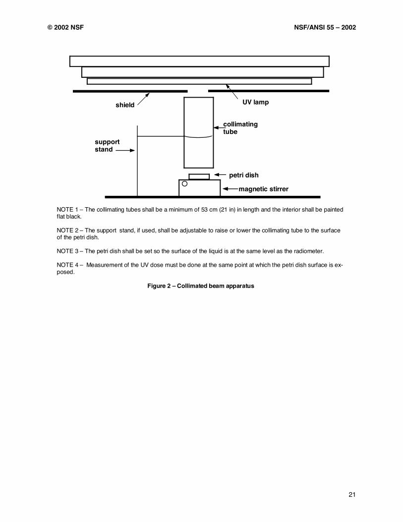
© 2002 NSF NSF/ANSI 55 – 2002
21
shield UV lamp
NOTE 1 – The collimating tubes shall be a minimum of 53 cm (21 in) in length and the interior shall be painted flat black. NOTE 2 – The support stand, if used, shall be adjustable to raise or lower the collimating tube to the surface of the petri dish. NOTE 3 – The petri dish shall be set so the surface of the liquid is at the same level as the radiometer. NOTE 4 – Measurement of the UV dose must be done at the same point at which the petri dish surface is ex-posed.
Figure 2 – Collimated beam apparatus
support stand
collimating tube
petri dish
magnetic stirrer

NSF/ANSI 55 – 2002 © 2002 NSF
22
Water supply
Back flow preventer
Tank fill
valve
Drain line Tank
Any suitable pressure or delivery system
Diaphragm pressure
tank
Mixer
Pressure gauge
Pressure regulator
Test units
Pressure gauges
Cycling solenoid A Cycling
solenoid B
Product water sampling points (influent sampling when lamps
are disabled)
NOTE 1 – Faucet-attached systems and portable systems shall be placed after solenoid valves A and B. NOTE 2 – Solenoid valves shall be controlled by appropriate timer(s). NOTE 3 – Pressure gauges shall be located directly ahead of test units, and all plumbing downstream of pres-sure gauge shall not be less than the diameter at the connection to the tested unit.
Valves
Figure 3 - Example test apparatus
Pump
Water meters
Mechanical filter
NOTE 4 – Diameter of plumbing and equipment after test units shall not be less than the diameter at the connection to the tested unit.
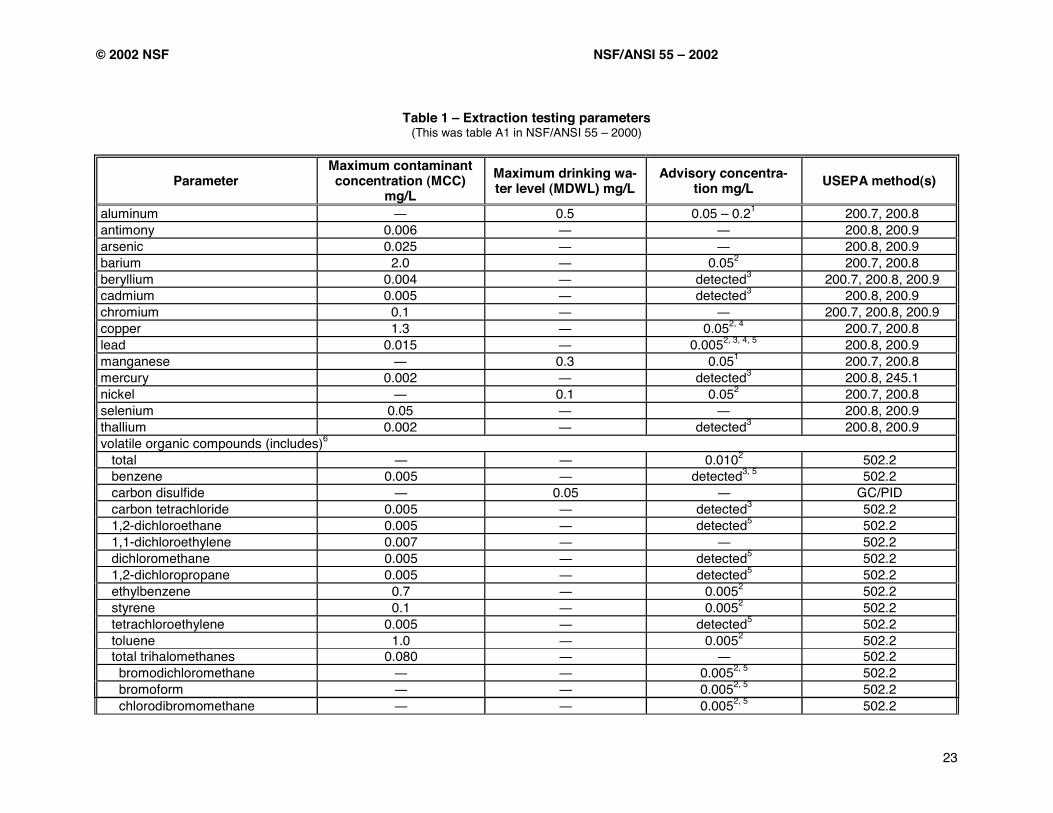
© 2002 NSF NSF/ANSI 55 – 2002
23
Table 1 – Extraction testing parameters
(This was table A1 in NSF/ANSI 55 – 2000)
Parameter Maximum contaminant concentration (MCC)
mg/L Maximum drinking wa-ter level (MDWL) mg/L
Advisory concentra-tion mg/L USEPA method(s)
aluminum 0.5 0.05 – 0.21 200.7, 200.8 antimony 0.006 200.8, 200.9 arsenic 0.025 200.8, 200.9 barium 2.0 0.052 200.7, 200.8 beryllium 0.004 detected3 200.7, 200.8, 200.9 cadmium 0.005 detected3 200.8, 200.9 chromium 0.1 200.7, 200.8, 200.9 copper 1.3 0.052, 4 200.7, 200.8 lead 0.015 0.0052, 3, 4, 5 200.8, 200.9 manganese 0.3 0.051 200.7, 200.8 mercury 0.002 detected3 200.8, 245.1 nickel 0.1 0.052 200.7, 200.8 selenium 0.05 200.8, 200.9 thallium 0.002 detected3 200.8, 200.9 volatile organic compounds (includes)6
total 0.0102 502.2 benzene 0.005 detected3, 5 502.2 carbon disulfide 0.05 GC/PID carbon tetrachloride 0.005 detected3 502.2 1,2-dichloroethane 0.005 detected5 502.2 1,1-dichloroethylene 0.007 502.2 dichloromethane 0.005 detected5 502.2 1,2-dichloropropane 0.005 detected5 502.2 ethylbenzene 0.7 0.0052 502.2 styrene 0.1 0.0052 502.2 tetrachloroethylene 0.005 detected5 502.2 toluene 1.0 0.0052 502.2 total trihalomethanes 0.080 502.2 bromodichloromethane 0.0052, 5 502.2 bromoform 0.0052, 5 502.2 chlorodibromomethane 0.0052, 5 502.2

NSF/ANSI 55 – 2002 © 2002 NSF
24
Table 1 – Extraction testing parameters (This was table A1 in NSF/ANSI 55 – 2000)
Parameter Maximum contaminant concentration (MCC)
mg/L Maximum drinking wa-ter level (MDWL) mg/L
Advisory concentra-tion mg/L USEPA method(s)
chloroform 0.0052, 5 502.2 1,1,1-trichloroethane 0.2 0.0052 502.2 1,1,2-trichloroethane 0.005 502.2 trichloroethylene 0.005 502.2 vinyl chloride 0.002 detected2, 5 502.2 o-,m-,p-xylene 10 0.0052 502.2 1 Based on the final USEPA Secondary Maximum Contaminant Level published in 56FR3573. For aluminum, the high level of 0.2 mg/L is shown to allow for products such as activated aluminum media. 2 Contaminant potentially contributed by other sources in the distribution and plumbing system. 3 Contaminant should not be intentionally present in drinking water treatment unit systems. 4 Subpopulations exist that are sensitive to exposure to this contaminant. 5 Contaminant has a Maximum Contaminant Level Goal (MCLG) of zero. 6 The referenced method includes approximately 60 chemicals. Testing for the chemicals as specifically listed is required. Others, if detected, shall be treated as having a 0.005 mg/L advisory concentration. An advisory concentration of 0.010 mg/L applies to total organic compounds.
– concluded –
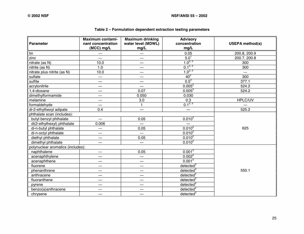
© 2002 NSF NSF/ANSI 55 – 2002
25
Table 2 – Formulation dependent extraction testing parameters
Parameter Maximum contami-nant concentration
(MCC) mg/L
Maximum drinking water level (MDWL)
mg/L
Advisory concentration
mg/L USEPA method(s)
tin 0.05 200.8, 200.9 zinc 5.01 200.7, 200.8 nitrate (as N) 10.0 1.02, 3 300 nitrite (as N) 1.0 0.12, 3 300 nitrate plus nitrite (as N) 10.0 1.02, 3 sulfate 402 300 sulfite 0.52 377.1 acrylonitrile 0.0052 524.2 1,4-dioxane 0.07 0.0052 524.2 dimethylformamide 0.050 0.030 melamine 3.0 0.3 HPLC/UV formaldehyde 1 0.12, 3 di-2-ethylhexyl adipate 0.4 525.2 phthalate scan (includes): butyl benzyl phthalate 0.05 0.0102 di(2-ethylhexyl) phthalate 0.006 di-n-butyl phthalate 0.05 0.0102 di-n-octyl phthalate 0.0102 diethyl phthalate 0.05 0.0102 dimethyl phthalate 0.0102
625
polynuclear aromatics (includes): naphthalene 0.05 0.0012 acenaphthylene 0.0022 acenaphthene 0.0012 fluorene detected2
phenanthrene detected2 anthracene detected2 fluoranthene detected2 pyrene detected2 benzo(a)anthracene detected2 chrysene detected2
550.1
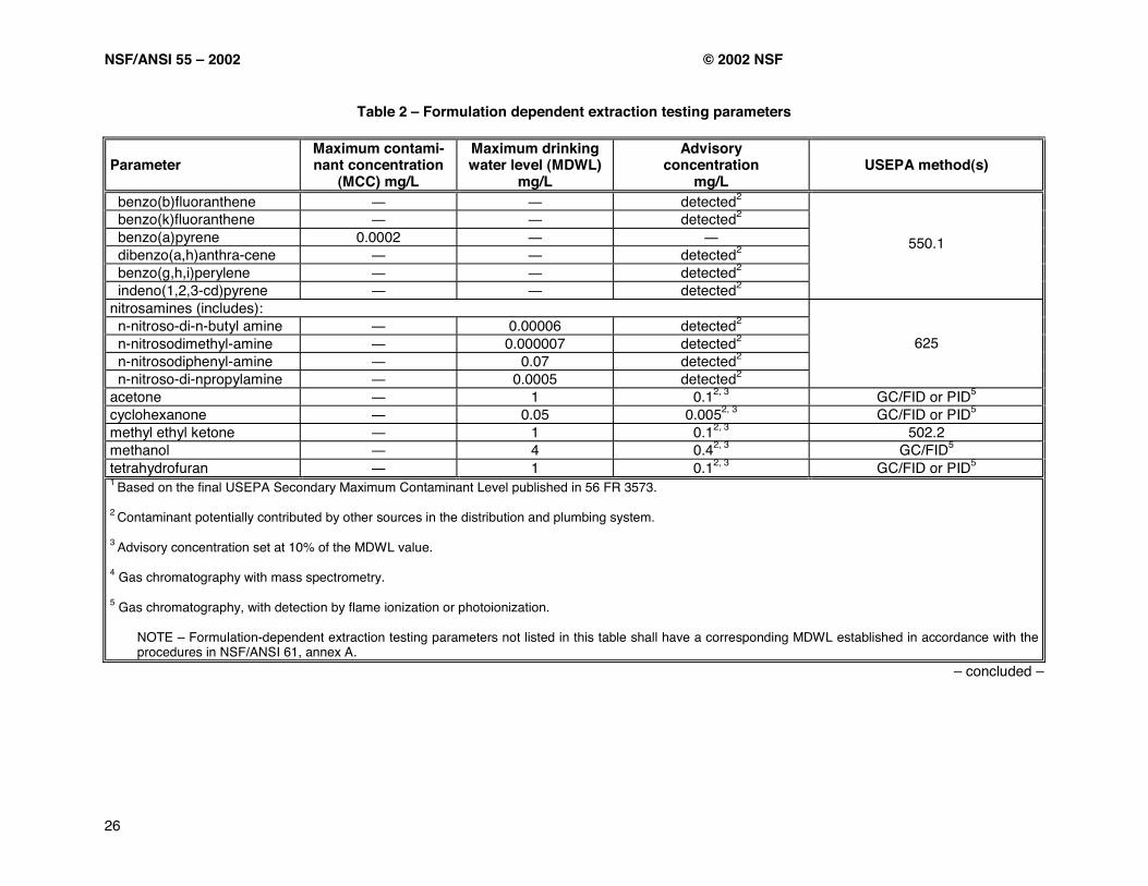
NSF/ANSI 55 – 2002 © 2002 NSF
26
Table 2 – Formulation dependent extraction testing parameters
Parameter Maximum contami-nant concentration
(MCC) mg/L
Maximum drinking water level (MDWL)
mg/L
Advisory concentration
mg/L USEPA method(s)
benzo(b)fluoranthene detected2 benzo(k)fluoranthene detected2 benzo(a)pyrene 0.0002 dibenzo(a,h)anthra-cene detected2 benzo(g,h,i)perylene detected2 indeno(1,2,3-cd)pyrene detected2
550.1
nitrosamines (includes): n-nitroso-di-n-butyl amine 0.00006 detected2 n-nitrosodimethyl-amine 0.000007 detected2 n-nitrosodiphenyl-amine 0.07 detected2 n-nitroso-di-npropylamine 0.0005 detected2
625
acetone 1 0.12, 3 GC/FID or PID5 cyclohexanone 0.05 0.0052, 3 GC/FID or PID5 methyl ethyl ketone 1 0.12, 3 502.2 methanol 4 0.42, 3 GC/FID5 tetrahydrofuran 1 0.12, 3 GC/FID or PID5 1 Based on the final USEPA Secondary Maximum Contaminant Level published in 56 FR 3573. 2 Contaminant potentially contributed by other sources in the distribution and plumbing system. 3 Advisory concentration set at 10% of the MDWL value. 4 Gas chromatography with mass spectrometry. 5 Gas chromatography, with detection by flame ionization or photoionization.
NOTE – Formulation-dependent extraction testing parameters not listed in this table shall have a corresponding MDWL established in accordance with the procedures in NSF/ANSI 61, annex A.
– concluded –
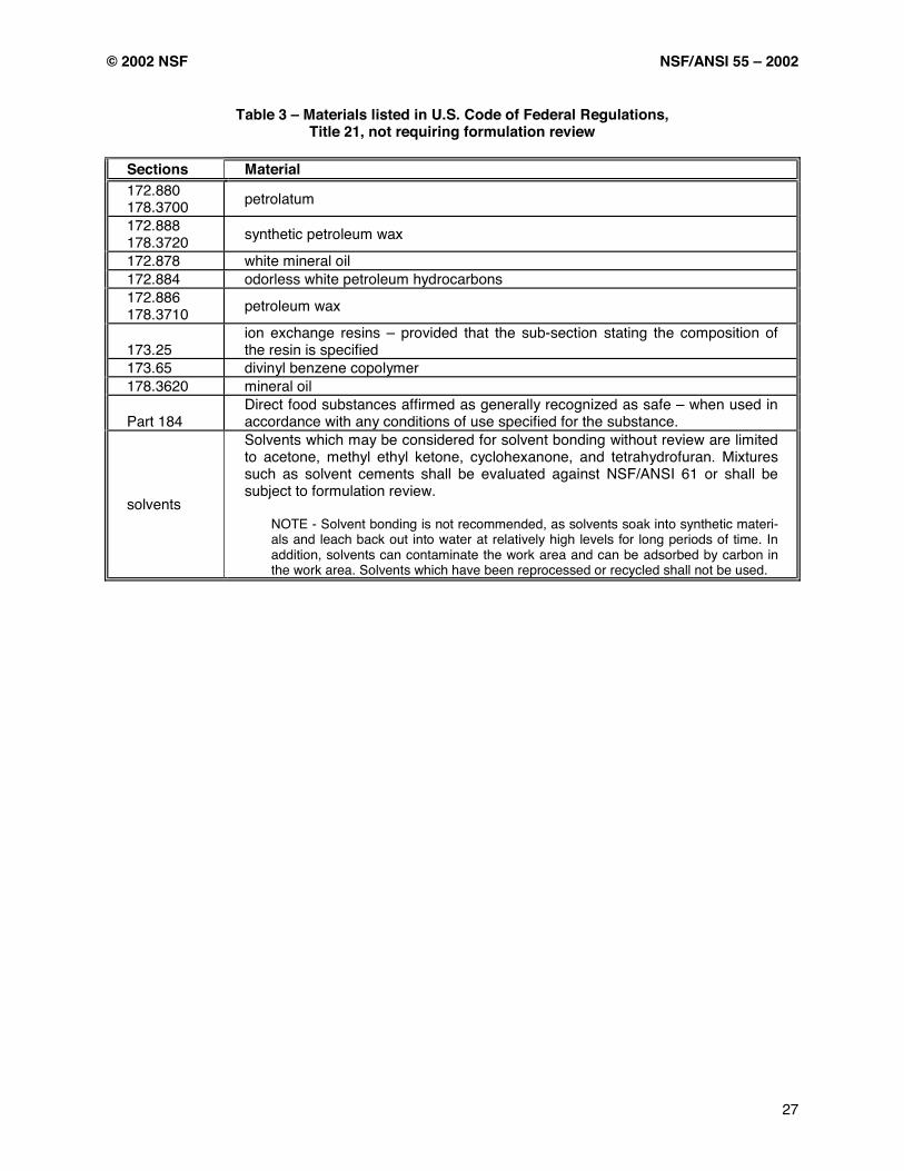
© 2002 NSF NSF/ANSI 55 – 2002
27
Table 3 – Materials listed in U.S. Code of Federal Regulations, Title 21, not requiring formulation review
Sections Material 172.880 178.3700 petrolatum
172.888 178.3720 synthetic petroleum wax
172.878 white mineral oil 172.884 odorless white petroleum hydrocarbons 172.886 178.3710 petroleum wax
173.25 ion exchange resins – provided that the sub-section stating the composition of the resin is specified
173.65 divinyl benzene copolymer 178.3620 mineral oil
Part 184 Direct food substances affirmed as generally recognized as safe – when used in accordance with any conditions of use specified for the substance.
solvents
Solvents which may be considered for solvent bonding without review are limited to acetone, methyl ethyl ketone, cyclohexanone, and tetrahydrofuran. Mixtures such as solvent cements shall be evaluated against NSF/ANSI 61 or shall be subject to formulation review.
NOTE - Solvent bonding is not recommended, as solvents soak into synthetic materi-als and leach back out into water at relatively high levels for long periods of time. In addition, solvents can contaminate the work area and can be adsorbed by carbon in the work area. Solvents which have been reprocessed or recycled shall not be used.

NSF/ANSI 55 – 2002 © 2002 NSF
28
Table 4 – Non-specific extraction testing parameters
Required parameter
Advisory concentra-tion (mg/L)
USEPA method(s) Follow-up testing1
phenolics 0.05 420.4 analysis for specific phenolic compound(s) in material formulations, Base/Neutral/Acid scan by GC/MS2
total organic carbon (TOC) 1.0 415.2
analysis for specific compound(s) in mate-rial formulations, GC/MS scan2 (for non-polar compounds), LC/MS3 (for target polar compounds)
Formulation dependent pa-rameter
Advisory concentra-tion (mg/L)
USEPA method(s) Follow-up testing1
total dissolved solids (TDS) 50 160.1 no follow-up recommended
total kjeldahl nitrogen (TKN) 0.5 351.2
analysis for specific compound(s) in mate-rial formulations, ammonium analysis, Base/Neutral scan by GC/MS2)(for non-polar compounds), LC/MS3)(for target polar compounds)
1 Follow-up testing may include one or more analyses. 2 Gas chromatography with mass spectroscopy (GC/MS). 3 Liquid chromatography with mass spectroscopy (LC/MS).
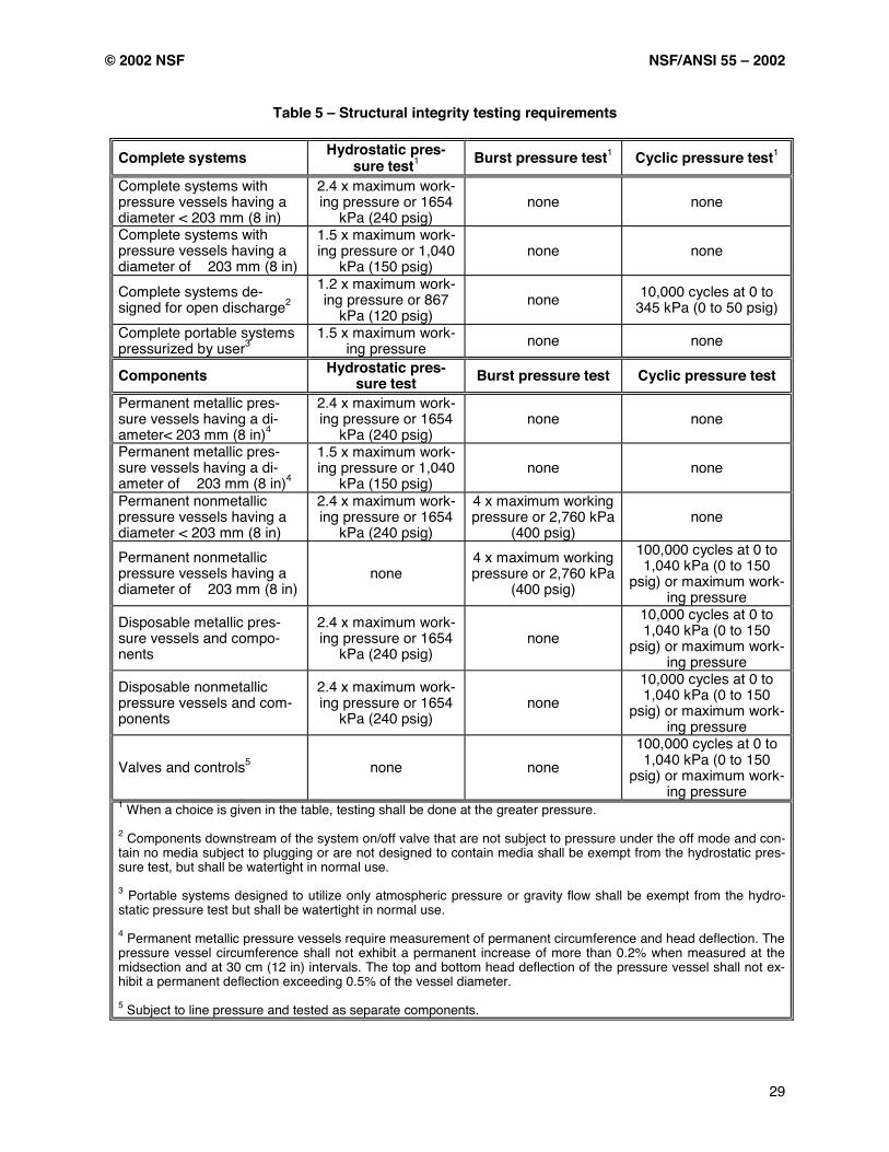
© 2002 NSF NSF/ANSI 55 – 2002
29
Table 5 – Structural integrity testing requirements
Complete systems Hydrostatic pres-sure test1 Burst pressure test1 Cyclic pressure test1
Complete systems with pressure vessels having a diameter < 203 mm (8 in)
2.4 x maximum work-ing pressure or 1654
kPa (240 psig) none none
Complete systems with pressure vessels having a diameter of 203 mm (8 in)
1.5 x maximum work-ing pressure or 1,040
kPa (150 psig) none none
Complete systems de-signed for open discharge2
1.2 x maximum work-ing pressure or 867
kPa (120 psig) none 10,000 cycles at 0 to
345 kPa (0 to 50 psig) Complete portable systems pressurized by user3
1.5 x maximum work-ing pressure none none
Components Hydrostatic pres-sure test Burst pressure test Cyclic pressure test
Permanent metallic pres-sure vessels having a di-ameter< 203 mm (8 in)4
2.4 x maximum work-ing pressure or 1654
kPa (240 psig) none none
Permanent metallic pres-sure vessels having a di-ameter of 203 mm (8 in)4
1.5 x maximum work-ing pressure or 1,040
kPa (150 psig) none none
Permanent nonmetallic pressure vessels having a diameter < 203 mm (8 in)
2.4 x maximum work-ing pressure or 1654
kPa (240 psig)
4 x maximum working pressure or 2,760 kPa
(400 psig) none
Permanent nonmetallic pressure vessels having a diameter of 203 mm (8 in)
none 4 x maximum working pressure or 2,760 kPa
(400 psig)
100,000 cycles at 0 to 1,040 kPa (0 to 150
psig) or maximum work-ing pressure
Disposable metallic pres-sure vessels and compo-nents
2.4 x maximum work-ing pressure or 1654
kPa (240 psig) none
10,000 cycles at 0 to 1,040 kPa (0 to 150
psig) or maximum work-ing pressure
Disposable nonmetallic pressure vessels and com-ponents
2.4 x maximum work-ing pressure or 1654
kPa (240 psig) none
10,000 cycles at 0 to 1,040 kPa (0 to 150
psig) or maximum work-ing pressure
Valves and controls5 none none 100,000 cycles at 0 to 1,040 kPa (0 to 150
psig) or maximum work-ing pressure
1 When a choice is given in the table, testing shall be done at the greater pressure. 2 Components downstream of the system on/off valve that are not subject to pressure under the off mode and con-tain no media subject to plugging or are not designed to contain media shall be exempt from the hydrostatic pres-sure test, but shall be watertight in normal use. 3 Portable systems designed to utilize only atmospheric pressure or gravity flow shall be exempt from the hydro-static pressure test but shall be watertight in normal use. 4 Permanent metallic pressure vessels require measurement of permanent circumference and head deflection. The pressure vessel circumference shall not exhibit a permanent increase of more than 0.2% when measured at the midsection and at 30 cm (12 in) intervals. The top and bottom head deflection of the pressure vessel shall not ex-hibit a permanent deflection exceeding 0.5% of the vessel diameter. 5 Subject to line pressure and tested as separate components.
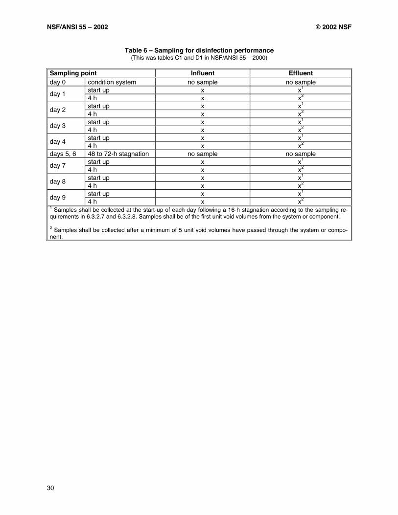
NSF/ANSI 55 – 2002 © 2002 NSF
30
Table 6 – Sampling for disinfection performance (This was tables C1 and D1 in NSF/ANSI 55 – 2000)
Sampling point Influent Effluent day 0 condition system no sample no sample
start up x x1 day 1 4 h x x2 start up x x1 day 2 4 h x x2 start up x x1 day 3 4 h x x2 start up x x1 day 4 4 h x x2
days 5, 6 48 to 72-h stagnation no sample no sample start up x x1 day 7 4 h x x2 start up x x1 day 8 4 h x x2 start up x x1 day 9 4 h x x2
1 Samples shall be collected at the start-up of each day following a 16-h stagnation according to the sampling re-quirements in 6.3.2.7 and 6.3.2.8. Samples shall be of the first unit void volumes from the system or component. 2 Samples shall be collected after a minimum of 5 unit void volumes have passed through the system or compo-nent.

© 2002 NSF NSF/ANSI 55 – 2002
A1
Annex A (normative)
Ultraviolet water treatment systems microbial reduction
A.1 Summary MS-2 Coliphage and Saccharomyces cerevisiae are used as biological surrogates to determine the average UV dose output of UV water treat-ment systems. The methods that are used for suspension preparation, titration and analysis of the challenge organisms for use in the sensitivity calibration and testing are presented in this an-nex. A.2 Equipment
– autoclave; – radiometer (International light IL-700); – UV collimating beam apparatus and 254 nm photo detector; – incubator, 35 ± 1 °C (95 ± 1 °F); – refrigerator, 5 ± 3 °C (41 ± 3 °F); – water bath 50 ± 1 °C (122 ± 1 °F); – freezer; – microwave; – vortex mixer; – UV-vis spectrophotometer; – pH meter; – hemocytometer; – colony counter; and – centrifuge.
A.3 Microorganisms All organisms shall be obtained from: American Type Culture Collection, 19301 Parklawn Drive, Rockville, Maryland 20852-1776
– Saccharomyces cerevisiae (ATCC
#18824); – MS-2 Coliphage (ATCC # 15597-Bl); and – Escherichia coli host strain (ATCC # 15597).
A.4 Supplies
– Petri dishes, 20 x 60 mm and 15 x 100 mm: sterile; – pipettes, 1 mL and 10 mL; sterile; – sterile centrifuge tubes, 10 mL and 50 mL; – sample bottles, 125 mL sterile screw cap; – test tubes, 16 x 125 mm; – sterile inoculating loop; – sterile filtration apparatus; – sterile 0.22 µm polycarbonate mem-brane filters; – Whatman #1 filter; – chlorine detection kit; and – disposable sterile 250 mL polypropylene container.
A.5 Reagents
– Sterile buffered dilution water (SBDW) shall be prepared according to the Standard Methods for the Examination of Water and Wastewater (dilution water: buffered water); – Phosphate buffer saline (PBS) – a stock solution shall be prepared by dissolving 80 g sodium chloride (NaCl), 2 g potassium dihy-drogen phosphate (KH2PO4), 29 g hydrated disodium hydrogen phosphate
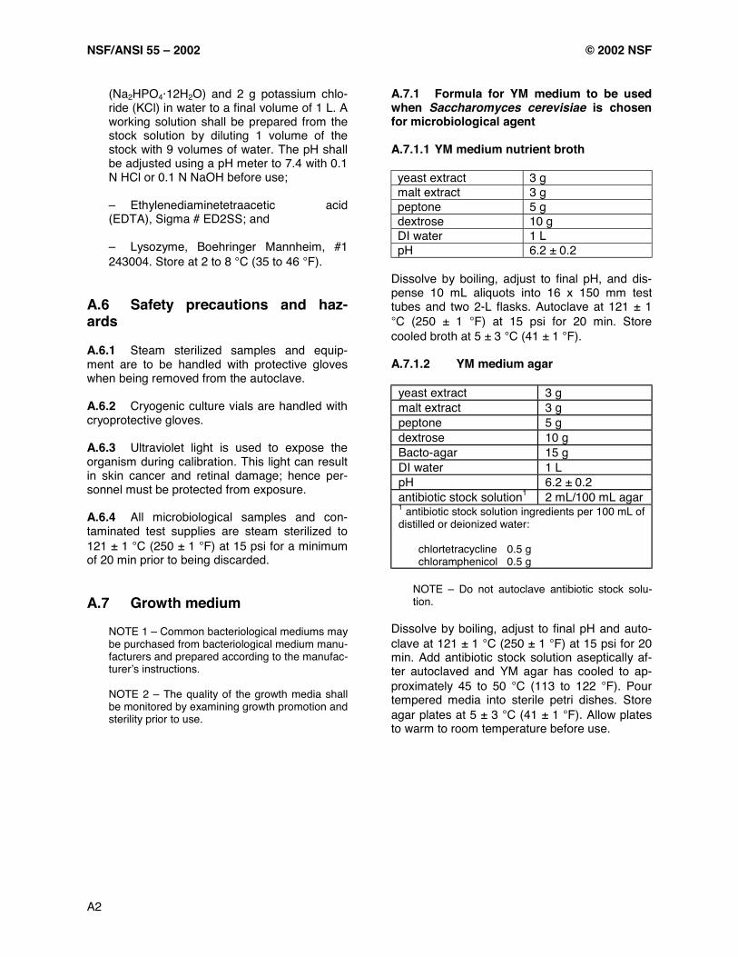
NSF/ANSI 55 – 2002 © 2002 NSF
A2
(Na2HPO4·12H2O) and 2 g potassium chlo-ride (KCl) in water to a final volume of 1 L. A working solution shall be prepared from the stock solution by diluting 1 volume of the stock with 9 volumes of water. The pH shall be adjusted using a pH meter to 7.4 with 0.1 N HCl or 0.1 N NaOH before use; – Ethylenediaminetetraacetic acid (EDTA), Sigma # ED2SS; and – Lysozyme, Boehringer Mannheim, #1 243004. Store at 2 to 8 °C (35 to 46 °F).
A.6 Safety precautions and haz-ards A.6.1 Steam sterilized samples and equip-ment are to be handled with protective gloves when being removed from the autoclave. A.6.2 Cryogenic culture vials are handled with cryoprotective gloves. A.6.3 Ultraviolet light is used to expose the organism during calibration. This light can result in skin cancer and retinal damage; hence per-sonnel must be protected from exposure. A.6.4 All microbiological samples and con-taminated test supplies are steam sterilized to 121 ± 1 °C (250 ± 1 °F) at 15 psi for a minimum of 20 min prior to being discarded. A.7 Growth medium
NOTE 1 – Common bacteriological mediums may be purchased from bacteriological medium manu-facturers and prepared according to the manufac-turer’s instructions. NOTE 2 – The quality of the growth media shall be monitored by examining growth promotion and sterility prior to use.
A.7.1 Formula for YM medium to be used when Saccharomyces cerevisiae is chosen for microbiological agent A.7.1.1 YM medium nutrient broth yeast extract 3 g malt extract 3 g peptone 5 g dextrose 10 g DI water 1 L pH 6.2 ± 0.2
Dissolve by boiling, adjust to final pH, and dis-pense 10 mL aliquots into 16 x 150 mm test tubes and two 2-L flasks. Autoclave at 121 ± 1 °C (250 ± 1 °F) at 15 psi for 20 min. Store cooled broth at 5 ± 3 °C (41 ± 1 °F). A.7.1.2 YM medium agar
yeast extract 3 g malt extract 3 g peptone 5 g dextrose 10 g Bacto-agar 15 g DI water 1 L pH 6.2 ± 0.2 antibiotic stock solution1 2 mL/100 mL agar 1 antibiotic stock solution ingredients per 100 mL of distilled or deionized water:
chlortetracycline 0.5 g chloramphenicol 0.5 g
NOTE – Do not autoclave antibiotic stock solu-tion.
Dissolve by boiling, adjust to final pH and auto-clave at 121 ± 1 °C (250 ± 1 °F) at 15 psi for 20 min. Add antibiotic stock solution aseptically af-ter autoclaved and YM agar has cooled to ap-proximately 45 to 50 °C (113 to 122 °F). Pour tempered media into sterile petri dishes. Store agar plates at 5 ± 3 °C (41 ± 1 °F). Allow plates to warm to room temperature before use.

© 2002 NSF NSF/ANSI 55 – 2002
A3
A.7.2 Formula to be used when MS-2 Col-iphage is chosen for microbiological agent A.7.2.1 TSB (Tryptic Soy Broth) tryptone 1.7 g soytone 0.3 g dextrose 0.25 g sodium chloride 0.5 g dipotassium phosphate 0.25 g DI water 100 mL pH 7.3 ± 0.2
Dissolve by boiling, adjust to final pH, and dis-pense 8 mL aliquots into 16 x 150 mm test tubes. Autoclave at 121 ± 1 °C (250 ± 1 °F) at 15 psi for 20 min. Store cooled broth at 5 ± 3 °C (41 ± 1 °F). A.7.2.2 1.5% TSA (Tryptic Soy Agar) tryptone 7.5 g soytone 2.5 g sodium chloride 2.5 g bacto-agar 7.5 g DI water 500 mL pH 7.3 ± 0.2
Dissolve by boiling, adjust to final pH and auto-clave at 121 ± 1 °C (250 ± 1 °F) at 15 psi for 20 min. Pour tempered media into sterile petri dishes. Store agar plates at 5 ± 3 °C (41 ± 1 °F). Allow plates to room temperature before use. A.7.3.3 Phage top agar 1% TSA (Tryptic Soy Agar) tryptone 7.5 g soytone 2.5 g sodium chloride 2.5 g agar 5.0 g DI Water 500 mL pH 7.3 ± 0.2
Dissolve by boiling, adjust to final pH, and auto-clave at 121 ± 1 °C (250 ± 1 °F) at 15 psi for 20 min. Store agar at 5 ± 3 °C (41 ± 1 °F). On the day of testing, liquefy and place in the 45 ± 1 °C (113 ± 1 °F) water bath. It is very important to keep the MS-2 Coliphage top agar at 45 ± 1 °C (113 ± 1 °F) to prevent agar solidification.
A.8 Culture of challenge organisms A.8.1 Saccharomyces cerevisiae A.8.1.1 Stock culture preparation of S. cere-visiae
a) Four days prior to preparing S. cere-visiae cells stock, inoculate a 10 mL tube of YM broth and incubate on a shaker water bath at 25 ± 1 °C (77 ± 1 °F) and approxi-mately 225 rpm for 24 ± 2 h. b) Perform this initial passing of the culture for three successive passes, each 24 ± 2 h, transferring to a fresh broth tube. c) After incubation time has elapsed on the third transfer, uniformly suspend the yeast cells in the tube and pipet 5 mL each to two 2-L flasks containing 1 L of YM broth in each. Incubate the inoculated flasks on a shaker water bath at 25 ± 1 °C (77 ± 1 °F) and approximately 225 rpm for 24 ± 2 h. d) Centrifuge the suspension at 2320 xg for 15 min. Carefully remove the super-natant. Pool all the cells from the 2 L of cen-trifuged suspension. e) Wash the cells 3 times using 99 mL ali-quots of buffered water for each wash. Cen-trifuge the suspension at 2320 xg for 15 min between washes and carefully decant su-pernatant. f) After removal of the supernatant on the third wash, resuspend the cells in 50 mL of buffered water. g) This final suspension shall be used for UV exposures in calibration and in testing of the treatment units. These cells must be used within 24 ± 2 h of harvest and stored at room temperature during this time. h) Titrate the S. cerevisiae cells as in A.8.1.2. The concentration of S. cerevisiae cells should be 107 to 108 CFU/mL. Use a hemocytometer to verify the appropriate concentration of S. cerevisiae cells.
A.8.1.2 Enumeration of S. cerevisiae cells
a) Determine the viable concentration of cells using a pour plate technique. Plate 10-5
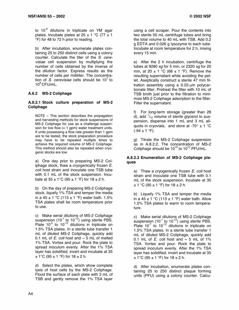
NSF/ANSI 55 – 2002 © 2002 NSF
A4
to 10-9 dilutions in triplicate on YM agar plates. Incubate plates at 25 ± 1 °C (77 ± 1 °F) for 48 to 72 h prior to reading. b) After incubation, enumerate plates con-taining 25 to 250 distinct cells using a colony counter. Calculate the titer of the S. cere-visiae cell suspension by multiplying the number of cells obtained by the inverse of the dilution factor. Express results as the number of cells per milliliter. The concentra-tion of S. cerevisiae cells should be 107 to 108 CFU/mL.
A.8.2 MS-2 Coliphage A.8.2.1 Stock culture preparation of MS-2 Coliphage
NOTE – This section describes the propagation and harvesting methods for stock suspensions of MS-2 Coliphage for use as a challenge suspen-sion for low flow (< 1 gpm) water treatment units. If units possessing a flow rate greater than 1 gpm are to be tested, the stock preparation procedure may have to be repeated multiple times to achieve the required volume of MS-2 Coliphage. This method should also be repeated when cryo-genic stocks are low.
a) One day prior to preparing MS-2 Col-iphage stock, thaw a cryogenically frozen E. coli host strain and inoculate one TSB tube with 0.1 mL of the stock suspension. Incu-bate at 35 ± 1°C (95 ± 1 °F) for 18 ± 2 h. b) On the day of preparing MS-2 Coliphage stock, liquefy 1% TSA and temper the media in a 45 ± 1 °C (113 ± 1 °F) water bath. 1.5% TSA plates shall be room temperature prior to use. c) Make serial dilutions of MS-2 Coliphage suspension (10-1 to 10-12) using sterile PBS. Plate 10-5 to 10-12 dilutions in triplicate on 1.5% TSA plates. In a sterile tube transfer 1 mL of diluted MS-2 Coliphage, quickly add 0.1 mL of E. coli host and ~ 5 mL of melted 1% TSA. Vortex and pour. Rock the plate to spread inoculum evenly. After the 1% TSA layer has solidified, invert and incubate at 35 ± 1°C (95 ± 1 °F) for 18 ± 2 h. d) Select the plates, which show complete lysis of host cells by the MS-2 Coliphage. Flood the surface of each plate with 3 mL of TSB and gently remove the 1% TSA layer
using a cell scraper. Pour the contents into two sterile 50 mL centrifuge tubes and bring the total volume to 40 mL with TSB. Add 0.2 g EDTA and 0.026 g lysozyme to each tube. Incubate at room temperature for 2 h, mixing every 15 min. e) After the 2 h incubation, centrifuge the tubes at 9280 xg for 5 min, or 2320 xg for 20 min, at 20 ± 1 °C (68 ± 1 °F). Remove the resulting supernatant while avoiding the pel-let. Aseptically construct a sterile 47 mm fil-tration assembly using a 0.22-µm polycar-bonate filter. Pretreat the filter with 10 mL of TSB broth just prior to the filtration to mini-mize MS-2 Coliphage adsorption to the filter. Filter the supernatant. f) For long-term storage (greater than 28 d), add 1/10 volume of sterile glycerol to sus-pension, dispense into 1 mL and 3 mL ali-quots in cryovials, and store at -70° ± 1 °C (-94 ± 1 °F). g) Titrate the MS-2 Coliphage suspension as in A.8.2.2. The concentration of MS-2 Coliphage should be 1010 to 1012 PFU/mL.
A.8.2.2 Enumeration of MS-2 Coliphage pla-ques
a) Thaw a cryogenically frozen E. coli host strain and inoculate one TSB tube with 0.1 mL of the stock suspension. Incubate at 35 ± 1 °C (95 ± 1 °F) for 18 ± 2 h. b) Liquefy 1% TSA and temper the media in a 45 ± 1 °C (113 ± 1 °F) water bath. Allow 1.5% TSA plates to warm to room tempera-ture. c) Make serial dilutions of MS-2 Coliphage suspension (10-1 to 10-12) using sterile PBS. Plate 10-7 to 10-12 dilutions in triplicate on 1.5% TSA plates. In a sterile tube transfer 1 mL of diluted MS-2 Coliphage, quickly add 0.1 mL of E. coli host and ~ 5 mL of 1% TSA. Vortex and pour. Rock the plate to spread inoculum evenly. After the 1% TSA layer has solidified, invert and incubate at 35 ± 1°C (95 ± 1 °F) for 18 ± 2 h. d) After incubation, enumerate plates con-taining 25 to 250 distinct plaque forming units (PFU) using a colony counter. Calcu-
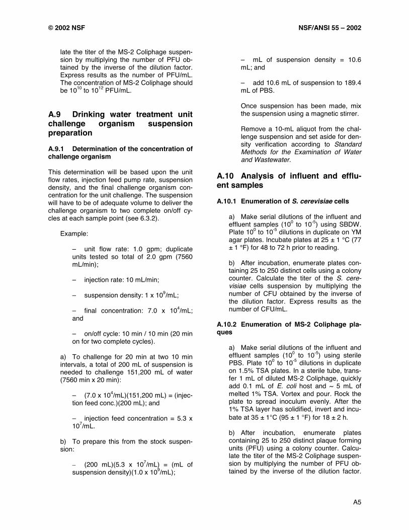
© 2002 NSF NSF/ANSI 55 – 2002
A5
late the titer of the MS-2 Coliphage suspen-sion by multiplying the number of PFU ob-tained by the inverse of the dilution factor. Express results as the number of PFU/mL. The concentration of MS-2 Coliphage should be 1010 to 1012 PFU/mL.
A.9 Drinking water treatment unit challenge organism suspension preparation A.9.1 Determination of the concentration of challenge organism This determination will be based upon the unit flow rates, injection feed pump rate, suspension density, and the final challenge organism con-centration for the unit challenge. The suspension will have to be of adequate volume to deliver the challenge organism to two complete on/off cy-cles at each sample point (see 6.3.2).
Example:
– unit flow rate: 1.0 gpm; duplicate units tested so total of 2.0 gpm (7560 mL/min); – injection rate: 10 mL/min; – suspension density: 1 x 10⁹/mL; – final concentration: 7.0 x 10⁴/mL; and – on/off cycle: 10 min / 10 min (20 min on for two complete cycles).
a) To challenge for 20 min at two 10 min intervals, a total of 200 mL of suspension is needed to challenge 151,200 mL of water (7560 min x 20 min):
– (7.0 x 10⁴/mL)(151,200 mL) = (injec-tion feed conc.)(200 mL); and
– injection feed concentration = 5.3 x 10⁷/mL.
b) To prepare this from the stock suspen-sion:
– (200 mL)(5.3 x 10⁷/mL) = (mL of suspension density)(1.0 x 10⁹/mL);
– mL of suspension density = 10.6 mL; and
– add 10.6 mL of suspension to 189.4 mL of PBS.
Once suspension has been made, mix the suspension using a magnetic stirrer. Remove a 10-mL aliquot from the chal-lenge suspension and set aside for den-sity verification according to Standard Methods for the Examination of Water and Wastewater.
A.10 Analysis of influent and efflu-ent samples A.10.1 Enumeration of S. cerevisiae cells
a) Make serial dilutions of the influent and effluent samples (100 to 10-5) using SBDW. Plate 100 to 10-5 dilutions in duplicate on YM agar plates. Incubate plates at 25 ± 1 °C (77 ± 1 °F) for 48 to 72 h prior to reading. b) After incubation, enumerate plates con-taining 25 to 250 distinct cells using a colony counter. Calculate the titer of the S. cere-visiae cells suspension by multiplying the number of CFU obtained by the inverse of the dilution factor. Express results as the number of CFU/mL.
A.10.2 Enumeration of MS-2 Coliphage pla-ques
a) Make serial dilutions of the influent and effluent samples (100 to 10-5) using sterile PBS. Plate 100 to 10-5 dilutions in duplicate on 1.5% TSA plates. In a sterile tube, trans-fer 1 mL of diluted MS-2 Coliphage, quickly add 0.1 mL of E. coli host and ~ 5 mL of melted 1% TSA. Vortex and pour. Rock the plate to spread inoculum evenly. After the 1% TSA layer has solidified, invert and incu-bate at 35 ± 1°C (95 ± 1 °F) for 18 ± 2 h. b) After incubation, enumerate plates containing 25 to 250 distinct plaque forming units (PFU) using a colony counter. Calcu-late the titer of the MS-2 Coliphage suspen-sion by multiplying the number of PFU ob-tained by the inverse of the dilution factor.

NSF/ANSI 55 – 2002 © 2002 NSF
A6
Express results as the number of PFU/mL. A.11 Challenge verification After the appropriate incubation period for MS-2 Coliphage or S. cerevisiae, count colonies on all of the density determination plates. Calculate
the mean number of microorganisms per millili-ter for plates with 25 to 250 colonies/plaques. This is to verify that challenge organism was present in the challenge test water at the opti-mum concentration before being added to test apparatus.

© 2002 NSF NSF/ANSI 55 – 2002
B1
Annex B15
Key elements of a certification program for drinking water treatment systems and components
15 The information contained in this Annex is not part of this American National Standard (ANS) and has not been processed in accordance with ANSI’s requirements for an ANS. As such, this Annex may contain material that has not been subjected to public review or a consensus process. In addition, it does not contain requirements necessary for conformance to the Standard.
A certification program for drinking water treat-ment systems and components should contain the following program elements: B.1 Marking the product Requirements for product marking including:
– Certified systems should bear a regis-tered trademark of the certifying organiza-tion. – Certified components intended to be used with other components to make a complete functional system, as defined by NSF/ANSI Standard 55, should bear a com-ponent mark. – Each system should have a model des-ignation. – Each system should bear a statement of claims verified through the certifying organi-zation and substantiated by test data.
B.2 Listing certified companies A published listing of all certified systems and components. The listing format should include at least the following information:
– company name and address; – product description; – trademark/model designation; – flow rate; – rated capacity or service cycle; and – each substance reduction claim that has been successfully evaluated and is sup-
ported by test data. B.3 Annual audits Actual physical audits of all facilities and produc-tion locations of the certified company at least annually. B.4 Testing Testing in accordance with all applicable NSF/ANSI Standard 55 requirements prior to certification.
– A retest program that includes reevalu-ation and retesting at least once every five years.
B.5 Toxicological evaluation of ma-terials formulations Formulation information of each material used in the fabrication of the system and/or components shall be provided to and maintained on file by the certifying organization. The formulation in-formation should include, at a minimum:
– the complete chemical identity or pro-portion by weight; – ingredient sources of supply – documentation regarding the health ef-fects concern of each ingredient in the mate-rial; and – documentation regarding the suitability of each ingredient for use in potable-water-contact material.

© 2002 NSF NSF/ANSI 55 – 2002
B2
B.6 Corrective action Corrective action for all items of noncompliance found during audits and reevaluation including:
– provisions for review and authorization for modifications to designs; – modifications to certified system and/or components; and – documentation and authorization of the modification maintained on file.
B.7 Enforcement To preserve the integrity of the registered trademark of the certifying organization and pro-tect public health, enforcement action should be taken by the certifier for the following:
– use of the registered trademark of the certifying organization on a non-certified product; – general noncompliance; – unauthorized change to a certified prod-uct; – unauthorized shipment or disposal of product placed on hold; and – bribes.
B.8 Administrative review Provisions for an administrative review as re-quested by any party directly affected by a deci-sion or action of the certifier. B.9 Appeals Provisions for an appeals process as requested by any party directly affected by a decision or action of the certifier resulting from an adminis-trative review.
B.10 Complaints Provisions for investigation of complaints related to certified products, misuse of the registered trademark of the certifying organization by a cer-tified company, or use/misuse of the registered trademark of the certifying organization by a non-certified company.
– certified company retention and disclo-sure of complaint records and remedial ac-tions for certified products.
B.11 Advertising Requirement of proper use of the registered trademark of the certifying organization on sales literature, technical publications, promotional materials, packaging, catalogs, and advertising. B.12 Records Provisions for verification of complete certified company records, including:
– installation and service for fabricators and distributors;
– purchased materials and components;
and
– production, shipment, and inventory. B.13 Public notice Provisions for issuing a public notice for non-compliance with any requirement of certification. B.14 Confidentiality A strict policy of non-disclosure of any confiden-tial information supplied to the certifier by the company regarding the product, including formu-lations, components, processes, ingredients, or the identity of the company’s suppliers and dis-tributors.
The information contained in this section is not part of this American National Standard (ANS) and has not been
processed in accordance with ANSI’s requirements for an ANS. As such, this section may contain material that has not been
subjected to public review or a consensus process. In addition, it does not contain requirements necessary for conformance to
the Standard.

THE STRONGEST MARKIN THE WATER TREATMENT BUSINESS!
®
The Public Health and Safety Company™
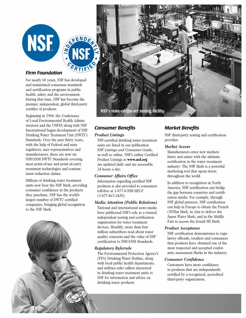
Firm FoundationFor nearly 60 years, NSF has developed and maintained consensus standards and certification programs in publichealth, safety and the environment. During that time, NSF has become thepremier, independent, global third-partycertifier of products.
Beginning in 1968, the Conference of Local Environmental Health Admin-istrators and the USEPA along with NSFInternational began development of NSFDrinking Water Treatment Unit (DWTU)Standards. Over the past thirty years,with the help of Federal and state regulators, user representatives andmanufacturers, there are now sixNSF/ANSI DWTU Standards coveringmost point-of-use and point-of-entrytreatment technologies and contam-inant reduction claims.
Millions of drinking water treatment units now bear the NSF Mark, providingconsumer confidence in the productsthey purchase. NSF has the world’slargest number of DWTU certified companies, bringing global recognition to the NSF Mark.
Market BenefitsNSF third-party testing and certification provides:
Market AccessManufacturers enter new markets faster and easier with the ultimate certification in the water treatmentindustry. The NSF Mark is a powerfulmarketing tool that opens doorsthroughout the world.
In addition to recognition in NorthAmerica, NSF certification can bridgethe gap between countries and certifi-cation marks. For example, throughNSF global partners, NSF certificationcan help in Europe to obtain the FrenchCSTBat Mark, in Asia to deliver theJapan Water Mark, and in the MiddleEast to access the Israeli SII Mark.
Product AcceptanceNSF certification demonstrates to regu-latory officials, retailers and consumersthat products have obtained one of themost respected and accepted confor-mity assessment Marks in the industry.
Consumer ConfidenceCustomers have more confidence in products that are independently certified by a recognized, accredited third-party organization.
Consumer BenefitsProduct Listings
NSF-certified drinking water treatmentunits are listed in our publication NSF Listings and Consumer Guide,as well as online. NSF’s online CertifiedProduct Listings at www.nsf.orgare updated daily and are accessible 24 hours a day.
Consumer Affairs OfficeInformation regarding certified NSFproducts is also provided to consumerstoll-free at 1-877-8-NSF-HELP (1-877-867-3435).
Media Attention (Public Relations)National and international news mediahave publicized NSF’s role as a trusted,independent testing and certificationorganization for water treatmentdevices. Monthly, more than fourmillion subscribers read about waterquality concerns and the value of NSFcertification to NSF/ANSI Standards.
Regulatory ReferralsThe Environmental Protection Agency’s(EPA) Drinking Water Hotline, alongwith local public health departments,and utilities refer callers interested in drinking water treatment units toNSF for information and advice ondrinking water products.
•IN
DEPENDENTLY•
C
E R T I F I E D
NSF’s state-of-the-art testing facility.
®

CredibilityNSF certification programs are accred-ited to the international standards forthird-party product certifiers throughthe American National Standards Insti-tute (ANSI) and the Standards Councilof Canada, assuring the highest level of integrity, quality and acceptance.
Full CapabilitiesThe NSF professional staff includeschemists, engineers, microbiologists andtoxicologists. Each has the experienceand background needed to assure propercompliance with the applicable standards.
NSF maintains state-of-the-art, in-houseDWTU testing laboratories in Ann Arbor,Michigan and Sacramento, California. In the past five years, NSF has more thanquadrupled the testing capacity in orderto provide fast turnaround times for bothcertification and R&D testing.
The Six NSF/ANSI Standards■ Standard 42: Drinking Water
Treatment Units – Aesthetic Effects■ Standard 53: Drinking Water
Treatment Units – Health Effects■ Standard 44: Residential Cation
Exchange Water Softeners■ Standard 55: Ultraviolet Microbio-
logical Water Treatment Systems■ Standard 58: Reverse Osmosis
Drinking Water Treatment Systems■ Standard 62: Drinking Water
Distillation Systems
Standard 42 and 53 cover carbon and mechanical filtration type systems. Standard 42 includes aesthetic claimssuch as chlorine, taste and odor, parti-culate and bacteriostasis. Standard 53covers health claims such as lead, VOC’s,pesticides, herbicides, cyst and the gasoline additive MTBE.
Standard 44 addresses water softeners, testing for hardness reduction, efficiencyrating as well as radium and barium
reduction. Standard 55 covers ultravioletdisinfection systems for bacterial andviral claims. Standard 58 covers reduc-tion claims for reverse osmosis, such as fluoride, hexavalent and trivalentchromium, TDS and nitrate/nitrite reduction. Finally, Standard 62 coversthe evaluation of distillation systems and reduction claims like mercury,nitrate/nitrite, arsenic and bacteria.
Component CertificationIn addition to product certification of complete treatment systems, individ-ual components are also NSF Certified to the NSF/ANSI DWTU standards. The process is very similar but offers the following benefits:
FasterTurnaround times are reduced for certification of systems using certifiedcomponents, as NSF already has on file all of the required material formulations for the component.
Cost-EffectiveThe cost is reduced for certification of components, as no contaminantreduction claims testing is necessary. In addition, systems using certifiedcomponents will not need to repeat certain steps and evaluations.
Compliance ConfidenceSystems that use certified componentshave the assurance that the materialsextraction and structural integrityrequirements of the standard are not compromised.
Fully Certified and ListedCertified components appear in NSFlisting under the applicable standard,the same as certified systems. This provides other companies a directory of components to assist with systemmanufacturing and certification.
Component certification is a fast andcost-efficient way to promote your components as leaders in the water filtration market.
Four Easy Steps to CertificationFour Easy Steps to CertificationOur professional staff is trained to assistproduct manufacturers in completing thecertification process in a timely manner.
Through our easy three-step process, NSFInternational evaluates products againstthe applicable NSF/ANSI Standard.
1ApplicationThe manufacturer provides informationon the product and materials of construc-tion. Following review, NSF requestsproduct be submitted.
2Product EvaluationStructural Integrity. Structural evalu-ation of the drinking water treatment unit or pressure-bearing component is required, and may include cyclic, hydrostatic, and burst evaluations,depending on the product type.
Material Evaluation. Toxicologicalassessment and acceptance of all materials used in the fabrication of the product is required. In addition, extraction testing and health effectsassessments are performed for all materials coming into contact with thewater. This ensures the product is notadding any substance of toxicological significance to the drinking water.
Performance Testing. Selection of conta-minant reduction claims is made by themanufacturer. Testing is then performedaccording to the test methodology andcriteria of the applicable standard.
Literature. Review and acceptance of all labeling and sales literature used with the product is required.
3Plant AuditAn inspection of the production facility,which may take place at any point in the process, verifies manufacturer compliance with the applicable productspecifications. Annual monitoring and follow-up services are conducted toensure continued compliance.
4CertificationNSF Certification is issued after allrequirements have been successfullycompleted. Products are listed in theNSF’s Consumer Book as well as on our web sight, www.nsf.org.

Standards and Criteria16 The following standards and criteria established and adopted by NSF as minimum voluntary consensus standards are used internationally: 2 Food equipment 3 Commercial warewashing equipment 4 Commercial cooking, rethermalization, and powered hot food holding and transport equipment 5 Water heaters, hot water supply boilers, and heat recovery equipment 6 Dispensing freezers 7 Commercial refrigerators and freezers 8 Commercial powered food preparation equipment 12 Automatic ice making equipment 13 Refuse processors and processing systems 14 Plastics piping system components and related materials 18 Manual food and beverage dispensing equipment 20 Commercial bulk milk dispensing equipment 21 Thermoplastic refuse containers 24 Plumbing system components for manufactured homes and recreational vehicles 25 Vending machines for food and beverages 29 Detergent and chemical feeders for commercial spray-type dishwashing machines 35 High pressure decorative laminates (HPDL) for surfacing food service equipment 36 Dinnerware 37 Air curtains for entranceways in food and food service establishments 40 Residential wastewater treatment systems 41 Non-liquid saturated treatment systems 42 Drinking water treatment units – Aesthetic effects 44 Residential cation exchange water softeners 46 Evaluation of components and devices used in wastewater treatment systems 49 Class II (laminar flow) biohazard cabinetry 50 Circulation system components and related materials for swimming pools, spas/hot tubs 51 Food equipment materials 52 Supplemental flooring 53 Drinking water treatment units – Health effects 55 Ultraviolet microbiological water treatment systems 58 Reverse osmosis drinking water treatment systems 59 Mobile food carts 60 Drinking water treatment chemicals – Health effects 61 Drinking water system components – Health effects 62 Drinking water distillation systems 75 Non-potentially hazardous foods 116 Non-food compounds used in food processing facilities – Food grade lubricants (draft standard for trial use) 173 Dietary supplements (draft standard for trial use) 184 Residential dishwashers 14159 Safety of machinery – Hygiene requirements for the design of machinery 14159-1 Hygiene requirements for the design of meat and poultry processing equipment C-2 Special equipment and/or devices
16 The information contained in this Standards and Criteria page is not part of this American National Standard (ANS) and has not been processed in accordance with ANSI’s requirements for an ANS. As such, this Standards and Crite-ria page may contain material that has not been subjected to public review or a consensus process. In addition, it does not contain requirements necessary for conformance to the Standard.

Printed 1/29/02