Embed Size (px)
Citation preview

1
Abstract— This paper describes the use of ultrasonic
nondestructive evaluation in corrosion detection of aircrafts
structures. Initiating on the inside or in the interface of an
aircraft’s skin, the corrosion must be tested from the outside
surface. Corroded aluminum as well as corrosion simulation
samples were inspected using pulse-echo technique of
ultrasonic nondestructive evaluation and the values of the
remaining thickness obtained was compared with the non-
corroded plate of the same type of aluminum alloy. Surface
roughness of those plates was also investigated to establish its
relation with the determined remaining thicknesses. The
estimated depth of the real corrosion by this method shows
good agreement with that measured with a micrometer.
Keywords: Ultrasonic, A-scan, Hidden corrosion,
Nondestructive evaluation, Aluminum
I. INTRODUCTION
OST metals used in aircraft structures are subjected
to degradation due to exposure to adverse
environments including humidity-induced stresses and wide
temperature excursions [1]. These conditions may cause
localized corrosion attacks in various forms. The severity of
corrosion attacks varies with aircraft type, design
techniques, operating environments, and operators'
maintenance programs [2].
When an aircraft lands and the door is opened, the inside
of the plane often fills with warm moist air. When the plane
takes flight and reaches altitude, the skin of the aircraft
becomes very cold due to the temperature of the outside air.
This causes moisture in the air inside the cabin to condense
on the inside of the aircraft skin. The water will collect at
low areas and serve as the electrolyte needed for corrosion
to occur. Furthermore, it has been found that some aircraft
corrosion rather than fatigue cracking will be life-limiting
such that corrosion can have a detrimental effect on the
integrity of aircraft structures by promoting fatigue crack
initiation and growth, and by decreasing the residual
This work was supported by IIUM (grant EDW B0805-138).
Meftah Hrairi is with the Mechanical Engineering Department,
International Islamic University Malaysia, P.O. Box 10, 50728 Kuala
Lumpur MALAYSIA (phone: 603-6196-4581; fax: 603-6196-4455; e-mail:
Nurul Farahana Zuhudi had graduated from the Mechanical Engineering
Department, International Islamic University Malaysia, P.O. Box 10, 50728
Kuala Lumpur, MALAYSIA.
strength of components.
Generally, pitting, crevice, and exfoliation corrosion are
the most common forms of corrosion in aircraft aluminum
alloys and, although considerable research has been
conducted on electrochemical and metallurgical aspects of
these forms of corrosion, little is known about the kinetics
of corrosion initiation and propagation.
Despite careful maintenance programs to assure a lower
rate of progress of such corrosion damage (proper sealing
or cleaning in galley area, proper draining, etc.), corrosion
does occur and effective inspection techniques are needed to
detect them as early as possible. Detection of each of the
corrosion types that can be induced in an aircraft metallic
structure may require a different inspection approach due to
the unique characteristics that are involved [1].
Several nondestructive evaluation (NDE) methods are
widely used for corrosion detection and evaluation. When
the inspected area is physically accessible, visual tests are
commonly used for periodic checks. Sometimes, tools such
as magnifying glasses and borescopes are employed for
further evaluation and for less accessible areas, respectively
[2]. The inspection involves a visual search for cracks,
change of color, change of texture, or bulges. Surface
corrosion at its embryonic stage can be visually detected
from localized indication such as discoloration, faint
powder lines, pimples on the paint and paint damage.
Concealed corrosion is very difficult to detect since in most
cases the characteristics of the damage are not sufficient to
trigger an indication in conventional NDE tests.
Generally, several NDE methods are available to detect
and characterize hidden corrosion including X-ray and
neutron radiography, ultrasonic, eddy current and acoustic
emission. All existing NDE methods for detection of
corrosion are limited in capability and sensitivity.
Frequently, corrosion is detected only after several
subsequent inspection schedules, in which case the damage
is fairly extensive and may require the replacement of the
structural component involved. Complicating the inspection
for hidden corrosion is the presence of multiple structural
features. Several technologies are capable of performing
accurate measurements of material thickness when there is
only a single sheet of the material. However, for example
aircraft lap splices are composed of 2, 3 or 4 layers of
Ultrasonic Techniques for Detection of Thinning
Defects in Metal Plates
Meftah Hrairi and Nurul Farahana Zuhudi
M
Proceedings of EnCon2010
3rd
Engineering Conference on Advancement in Mechanical
and Manufacturing for Sustainable Environment
April 14-16, 2010, Kuching, Sarawak, Malaysia

2
material due to the presence of bonded doublers, tear straps
and stringers. Sometimes these layers are of different
alloys. [3]
Over 80 percent of the inspections done to an aircraft are
visual inspections. At regular intervals, inspectors look at
various components of the aircraft for signs of damage.
During heavy maintenance work, much of the interior of
the aircraft is stripped out so inspectors can look for
damage to the inside surface of the fuselage. However, not
all areas of the aircraft can be accessed for visual inspection
and not all damage can be detected by visual means. This is
where NDE plays a critical role in thoroughly inspecting
aircrafts.
NDE methods allow inspectors to inspect areas of the
plane that would otherwise be impossible to inspect without
disassembling the structure to gain access to the internal
areas. NDE methods also allow inspectors to detect damage
that is too small to be detected by visual means. Eddy
current and ultrasonic inspection methods are used
extensively to locate tiny cracks that would otherwise be
undetectable. These techniques are also used to measure the
thickness of the aircraft skin from the outside and detect
metal thinning from corrosion on the inside surface of the
skin [4]. X-ray techniques are used to find defects buried
deep within the structure and to locate areas where water
has penetrated into certain structures [5]. Obviously, this
task requires trained professionals who are capable of
performing a variety of different NDE techniques to get a
complete and accurate status of the airplane.
The main objective of this work is to demonstrate the use
of ultrasonic nondestructive evaluation (NDE) in corrosion
detection. In addition, surface roughness is commonly
associated with corrosion thus it has also become the major
interest of this experimental work along with the thickness
degradation of the inspected plate.
II. EXPERIMENTAL METHODOLOGY AND SPECIMENS
A. Materials
The principal material specimen used in this work is
Aluminum-7075 with thickness of 5±0.2mm. Other
materials involved were the Nomex honeycomb structure as
well as fiberglass epoxy composite laminate. Theoretical
acoustic properties of the design material specimen in this
project, found in the literature are tabulated in Table I.
Table I: Acoustic properties of the material specimen used [6]
Material Longitudinal
Velocity(c) m/s
Attenuation (β)
nepers
Aluminum-7075 6350 0
Fiberglass epoxy
composite laminate
2920 0.3
Nomex honeycomb - -
B. Test Specimens
Engineered specimens have been manufactured that
include corrosion thinning regions and corrosion by-
products. Three types of aluminum corrosion specimens
have been used in the ultrasonic wave experimental work.
1) Stepped aluminum plate
Figure 1 shows the detailed dimension of the corrosion
simulation specimen. Basically, a stepped aluminum plate
would be fabricated in three steps of 2, 2 and 1mm using
milling machine available in the laboratory. The stepped
behavior exhibited by the plate in this part basically
resembles the corrosion behavior where there is a variation
of thickness along the plate. Since the machining process is
expected to be a poor one, the margin of error is selected to
be ±0.5mm.
Figure 1 Stepped aluminum plate specimen
Before starting the machining of the aluminum plate
using the milling machine, the designed specimen
dimensions were precisely measured and marked to fulfill
the margin of ±0.5mm. Some precautionary steps were
taken and observed while completing the machining of the
specimen.
2) Controlled corrosion on aluminum plates
Tube controlled corrosion on aluminum plates was
conducted by filling PVC tubes mounted on the plates with
a potassium hydroxide (KOH) solution of multi-molarities
at a constant period of time. The weight loss of the
aluminum plate due to the KOH solution in the tubes may
be noted as a reduction in thickness of the plate. It is
desirable for the theoretical thickness value of the plate to
be measured using a micrometer and then compared to the
thickness obtained from the ultrasonic testing. Figure 2
illustrates the mounted PVC tubes on an aluminum plate to
provide the KOH solution contact areas.
It was noted from literature that KOH exhibits high
corrosivity behavior in the presence of aluminum, brass,
and zinc [7]. When it is wet, it attacks metals such as
aluminum, tin, lead, and zinc, producing flammable
hydrogen gas. In addition, its hygroscopic behavior when
dissolved in water or alcohol or when the solution is treated
with acid may lead to the generation of a great heat. All of
these unique behaviors of KOH have led it to be
implemented in this project.

3
Figure 2 Controlled corrosion specimen
The KOH solution for concentrations of 1, 2, 3, 4, 5, and
6 Mol were provided for the tube controlled corrosion to
occur on three aluminum plates that have been adhesively
mounted with the PVC tubes. A constant period of 60
minutes was allowed for all specimens to react with the
KOH solution in the tube. The initial and final weights of
the specimens was recorded to verify a thickness reduction
on the plates.
3) Corroded aluminum plate adhesively bonded to
multi-wall construction
Figure 3 demonstrates a resemblance of corroded
aluminum liner sitting in the multi-wall structure of the
external fuel tank. In this work, it is desirable to fabricate
this multi-wall structure as close as possible to the real one.
The controlled corrosion aluminum plate, fabricated as
shown in Figure 2, would be used to resemble the liner
while the fiberglass epoxy laminate and Nomex honeycomb
structure would also be used. An ultrasonic testing would be
carried out on the fabricated multi-wall to observe how the
waves travel inside the structure.
Figure 3 Corroded aluminum plate adhesively bonded to multi-wall
construction specimen
The corroded aluminum plate that was adhesively
bonded with the multi-wall structure was fabricated using
the method described in the above section B-2. However,
the corrosion region on the aluminum plate was only
exposed for 30 minutes to a concentration of 6M of KOH.
For the fiberglass epoxy laminate plate, hand layup method
was used to fabricate it. Ten layers of glass fiber were
alternately layered with epoxy hardener and then exposed to
a 500N force was exerted on the layer. The laminate was
allowed to harden for approximately 24 hours. The
honeycomb, fiberglass laminate composite, and the
corroded aluminum plate were adhesively glued in the
designed dimensions.
C. Ultrasonic Testing
The first step in the ultrasonic testing was a calibration
procedure, performed by positioning the transducer at a
distance from the specimen to discern noise signals from
the wave signals travelling within the specimens. Point by
point measurements of the thickness were taken on all
specimens and the mechanical thickness was obtained at
each marked point using a micrometer. The locations of the
measurement points on each specimen are shown in Figure
4. For all specimens, the inspection was conducted from the
back side of the corroded surface in order to detect if a
hidden corrosion occurred on those specimens. This
experiment requires a 5 MHz normal beam transducer for
pulse-echo method to determine the thickness of the
specimen from the A-Scan display. Oil was used as the
couplant throughout the testing.
(a)
(b)

4
(c)
Figure 4 Measurement points for (a) stepped aluminum plate (b) corroded
aluminum plate and (c) corroded aluminum plate on multi-wall structure
III. RESULTS AND DISCUSSIONS
A. Stepped aluminum plate results
Figure 5 shows the fabricated stepped aluminum liner
used in each step, S1, S2 and S3 has an average mechanical
thickness of 5.020, 4.060 and 2.395mm, respectively. As
compared with the average ultrasonic thickness obtained,
the deviation increases towards the downward step such
that the plate’s thickness is getting thinner. A wave that
propagates through a small distance tends to attenuate
more, causing disturbances to the signals. Table II contains
all the thickness values for the specimen.
Figure 5 Fabricated stepped aluminum plate
During the fabrication of the specimen, a slight bending
of the plate occurred. Due to the unique dimension of the
plate which is rectangular in shape with its length and
width ratio of 4 to 1, the milling blade tends to bend the
plate while machining. The bending of the plate led to a
variation in the surface roughness of the plate as illustrated
in Table II. The surface roughness will act as a filter that
will pass wavelengths below a certain frequency, partially
attenuate wavelengths over a frequency range and
completely block all wavelengths over a given frequency.
Indeed, low frequency waves will reflect cleanly, following
an “angle of incidence equals angle of reflection” rule.
However, as the wavelength becomes small (increasing
frequency) relative to the surface roughness the waves do
not reflect cleanly and are scattered as a function of relative
size [8]. It can be seen from Table II that as the roughness
of the measurement point increases it will cause unclear
echo signal edges thus resulting in less accurate readings of
thickness measurement. This is due to the fact that signal
information at higher frequencies is lost due to scattering.
Table II Thickness values for the fabricated stepped aluminum plate
Step No
S
Average
Mechanical
thickness
have mm
Average
Ultrasonic
thickness
hUT ave mm
%
Error
Roughness
Ra (µm)
1 5.02 4.92 1.99 1.22
2 4.06 3.96 2.46 1.30
3 2.33 2.15 7.72 1.56
The thickness measurement using the ultrasonic A-scan
signal, hUT, is illustrated in Figure 5. The thickness
measured at point 1 on step 1 corresponds to the distance
between two consecutive peaks which in this case is equal
to 5.0 mm.
Figure 6 Ultrasonic A-scan display for the step 1 of aluminum plate at
measurement point1
Similarly, the ultrasonic thickness, hUT, at points 2 and 3
for step S1, shown in Figures 7 and 8, are estimated at 4.9
mm and 4.85 mm leading to an average thickness of 4.92
mm. Comparing the latter to the thickness measured
mechanically using a micrometer, 5.02 mm, one obtains an
error of thickness estimation of 1.99%.
Figure 7 Ultrasonic A-scan display for the step 1 of aluminum plate at
measurement point2
S3 S2 S1
5
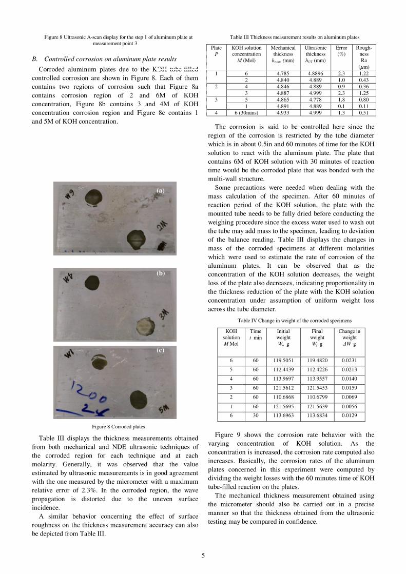
Figure 8 Ultrasonic A-scan display for the step 1 of aluminum plate at
measurement point 3
B. Controlled corrosion on aluminum plate results
Corroded aluminum plates due to the KOH tube-filled
controlled corrosion are shown in Figure 8. Each of them
contains two regions of corrosion such that Figure 8a
contains corrosion region of 2 and 6M of KOH
concentration, Figure 8b contains 3 and 4M of KOH
concentration corrosion region and Figure 8c contains 1
and 5M of KOH concentration.
Figure 8 Corroded plates
Table III displays the thickness measurements obtained
from both mechanical and NDE ultrasonic techniques of
the corroded region for each technique and at each
molarity. Generally, it was observed that the value
estimated by ultrasonic measurements is in good agreement
with the one measured by the micrometer with a maximum
relative error of 2.3%. In the corroded region, the wave
propagation is distorted due to the uneven surface
incidence.
A similar behavior concerning the effect of surface
roughness on the thickness measurement accuracy can also
be depicted from Table III.
Table III Thickness measurement results on aluminum plates
Plate
P
KOH solution
concentration
M (Mol)
Mechanical
thickness
hnom (mm)
Ultrasonic
thickness
hUT (mm)
Error
(%)
Rough-
ness
Ra
(µm)
1 6 4.785 4.8896 2.3 1.22
2 4.840 4.889 1.0 0.43
2 4 4.846 4.889 0.9 0.36
3 4.887 4.999 2.3 1.25
3 5 4.865 4.778 1.8 0.80
1 4.891 4.889 0.1 0.11
4 6 (30mins) 4.933 4.999 1.3 0.51
The corrosion is said to be controlled here since the
region of the corrosion is restricted by the tube diameter
which is in about 0.5in and 60 minutes of time for the KOH
solution to react with the aluminum plate. The plate that
contains 6M of KOH solution with 30 minutes of reaction
time would be the corroded plate that was bonded with the
multi-wall structure.
Some precautions were needed when dealing with the
mass calculation of the specimen. After 60 minutes of
reaction period of the KOH solution, the plate with the
mounted tube needs to be fully dried before conducting the
weighing procedure since the excess water used to wash out
the tube may add mass to the specimen, leading to deviation
of the balance reading. Table III displays the changes in
mass of the corroded specimens at different molarities
which were used to estimate the rate of corrosion of the
aluminum plates. It can be observed that as the
concentration of the KOH solution decreases, the weight
loss of the plate also decreases, indicating proportionality in
the thickness reduction of the plate with the KOH solution
concentration under assumption of uniform weight loss
across the tube diameter.
Table IV Change in weight of the corroded specimens
KOH
solution
M Mol
Time
t min
Initial
weight
Wo g
Final
weight
Wf g
Change in
weight
∆W g
6 60 119.5051 119.4820 0.0231
5 60 112.4439 112.4226 0.0213
4 60 113.9697 113.9557 0.0140
3 60 121.5612 121.5453 0.0159
2 60 110.6868 110.6799 0.0069
1 60 121.5695 121.5639 0.0056
6 30 113.6963 113.6834 0.0129
Figure 9 shows the corrosion rate behavior with the
varying concentration of KOH solution. As the
concentration is increased, the corrosion rate computed also
increases. Basically, the corrosion rates of the aluminum
plates concerned in this experiment were computed by
dividing the weight losses with the 60 minutes time of KOH
tube-filled reaction on the plates.
The mechanical thickness measurement obtained using
the micrometer should also be carried out in a precise
manner so that the thickness obtained from the ultrasonic
testing may be compared in confidence.
(a)
(b)
(c)

6
Figure 9 Corrosion rate behavior in function of KOH molarity
A sample calculation of the ultrasonic thickness, hUT on
plate 1 at region of concentration of KOH solution of 6M is
shown in Figure 10 where the distance between two
consecutive peaks is estimated to be 5.00 mm with a
relative error of 2.3%.
Figure 10 Ultrasonic single A-scan display at corroded region of plate 1
due to 6M of KOH solution
C. Corroded aluminum plate adhesively bonded to multi-
wall construction results
Figure 11 shows the fabricated multi-wall structure of the
fuel tank with a corroded aluminum plate as the liner.
Figure 11 Multi-wall construction of fuel tank.
Ultrasonic testing that has been done on the structure
showed that the longitudinal waves travel through the
structure is highly scattered and absorbed due to the
anisotropic behavior of the layers. Also, with the presence
of the honeycomb cellular structure, it is highly unlikely for
waves to travel through the honeycomb and be reflected
back to the transducer. This was validated by a pulse-echo
experiment in which multi-wall structure was insonified by
the 5 MHz transducer from the substrate side to detect the
hidden corrosion on the liner. As shown in Figure 12, no
signal was observed to be reflected to the transducer as the
signals obtained from all points of measurement remain
nearly the same as the calibration signal.
Figure 12 Ultrasonic testing signals for hidden corrosion of the multi-wall
structure
Even though ultrasonic bulk waves are often used in
thickness detection of plate structures by measuring the
time-of-flight as demonstrated with the first two types of
specimens, this technique showed its limitation when
inspecting multi-layered specimens, especially with
complex materials like honeycomb [9]. In the latter cases,
conventional ultrasonic methods need to be enhanced with
theoretical analyses such as standard Fast Fourier
Transform (FFT) and inverse algorithms in order to
reconstruct the thickness through a comparison of the
theoretical and measured resonant frequencies of the liner,
provided the acoustic properties of the liner are known a
priori. Furthermore, measurements should be carried out in
a wide frequency range to cover all materials making the
multilayer structure.
IV. CONCLUSION
Material specimens simulating the corroded aluminum
liner in the multi-wall construction of the fuel tank have
been successfully designed and fabricated which included a
stepped aluminum plate, a KOH tube-filled controlled
corrosion as well as a corroded aluminum plate on the
multi-wall structure.
The use of ultrasonic NDE in inspecting these fabricated
specimens has been well demonstrated. For the first two
types of specimens, the thickness obtained from both
mechanical and ultrasonic techniques have shown a range
of percentage deviation from 0.1 to 2.3 for the simulated
corrosion specimen and 1.99 to 7.72 in the case of the
stepped specimen. These errors are mainly attributed to the
poor handling of the measurement apparatus, the
micrometer as well as the ultrasonic testing apparatus. The
fabrication of the stepped aluminum plate also seems to be
poor with an overall error greater than 2%. Great attention
must be put on the quality of the surface to be tested, since
surface roughness can render the process ineffective and
inaccurate.
For the multiwall specimen, even though the thickness
reduction of the corroded plate was not able to be detected,
the behavior of the wave propagating through the multi-
wall structure may still be observed and analyzed with
reference to other advanced works.
7
ACKNOWLEDGMENT
The authors gratefully thank Mrs. Lynn Mason for her
help in editing this manuscript.
REFERENCES
[1] Y. Bar-Cohen, A. K. Mal; and M. Lasser, “NDE of hidden flaws in
aging Aircraft Structures using Obliquely Backscattered Ultrasonic
Signals (OBUS),” SPIE Conference on Nondestructive Evaluation of
Aging Aircraft, Airports, and Aerospace Hardware III, Vol. 3586, pp.
347-353, 1999.
[2] Y. Bar-Cohen, “Emerging NDE Technologies and Challenges at the
Beginning of the 3rd Millennium – Part II,” Material Evaluation, vol.
58, no. 2, pp. 141-150, February 2000.
[3] M. D. Bode, D. M. Ashbaugh, F. W. Spencer, and J. V. Zuffranieri,
“corrosion structured experiment – results from Engineered specimens,”
6th Joint FAA/DoD/NASA Aging Aircraft Conference, Sept.16-19,
2002
[4] J. Hoffmann and J. Ullett, “Nondestructive investigation of corrosion
damage in multi-layer structure,” 9th Joint FAA/DoD/NASA Aging
Aircraft Conference, Atlanta, March 2006.
[5] W. L. Dunn and A. M. Yacout, “Corrosion detection in aircraft by X-
ray backscatter methods,” Applied Radiation and Isotopes, vol. 53, no
4-5, pp. 625-632, November 2000.
[6] D. Roach, and L. Dorrell, “Development of Composite Honeycomb and
Solid Laminate Reference Standards to Aid Aircraft Inspections”,
NDT.net 4(3), 1999.
[7] C. Vargel, “Corrosion of Aluminum”, Elsevier, Amsterdam, 2004
[8] J. R. Tucker, “Ultrasonic Spectroscopy for Corrosion Detection and
Multiple Layer Bond Inspection,” Proceedings of the First Joint
DoD/FAA/NASA Conference on Aging Aircraft, vol. II, pp. 1537–
1550, 1998.
[9] W. Zhu, J. L. Rose, J. N. Barshinger, and V. S. Agarwala, “Ultrasonic
Guided Wave NDT for Hidden Corrosion Detection,” Res Nondestr
Eval 10, pp. 205–225, 1998.


![Thinning - [email protected] Home](https://img.dokumen.tips/doc/110x75/613d1c55736caf36b7596fee/thinning-emailprotected-home.jpg)