Embed Size (px)
Citation preview

Ultrasonic Sensors in Air Valentin Magori
Corporate Research and Development, Siemens AG. Munich, Germany
Abstract Ultrasonic Sensors in Air are Intelligent Sensors, which use wave-propagation phenomena in air to measure physi- cal or chemical variables. With accordance to the influence prin- ciple, two main types of ultrasonic sensors can be differentiated.
Propagation-Pafh Sensors decode changes on propagation to get a fast measurement of temperature, pressure variations or gas concentration. Most important are ultrasonic flow sensor e.g. for engine intake air or for aidgas measurement.
Distance-Sensors detect echoes from objects and evaluate their propagation time and amplitude. Examples are distance meters and presence detectors. By intelligent algorithms based on signal theory models or heuristic approaches (synthetic aper- ture, pulse holography, fuzzy or neural network etc.) the resolution and detection range were increased, the radial and la- teral resolution significantly enhanced and objects recognized.
With piezoelectric PVDF-foils efficient and versatile transduc- ers arrays were relized. Robust transducers for operation in ad- verse environment (dirt, moisture, abrasion) were developed using rugged matching layers or a special composite-transducer technology.
-
Fig. 1: Architecture of Ultrasonic Sensor Systems
1051-0117/94/0000-0471 $4.00 0 1994 IEEE 1994 ULTRASONICS SYMPOSIUM - 471
INTRODUCTION
Sensors are the sensing organs of technical systems. They collect information about variables in the environ- ment as well as on non-electrical system parameters. and provide the results as electrical signals. Sensors are an es- sential part of power generation and distribution systems, automated industrial processes, traffic management sy- stems, as well as environmental and health maintenance systems. The development of sensors was stimulated by modern microelectronics. Even relative complex sensors, which previously could be realized only as scientific in- struments [ I ] , are now feasible as compact devices at low costs. Further, the proliferation of control systems opened a high application potential [2] for ultrasonic sensors .
Ultrasonic sensors in air are based on the medium which is always present everywhere men are, and without which human life is impossible. These sensors measure quantities, which often are immediately relevant for hu- mans, such as the flow of air or short distances within a man’s reach. Moreover, these sensors imply generic approaches which could be used for other gases and even for liquids.
INTELLIGENT SENSOR SYSTEMS
Ultrasonic sonar sensors actively transmit acoustic wa- ves and receive them later. This is done by ultrasonic transducers, which transform an electrical signal into an ultrasonic wave and vice versa. Often i t is possible to use the same transducer for both transmitting and receiving. On its path from the transmitter to the receiver, the wave becomes modified by the situation under investigation (Fig. 1). The ultrasound signal carries the information ab- out the variables to be measured. The task for the ultraso- nic sensors is not merely to detect ultrasound. As inrefli- gent sensors they have to extract the information carried by the ultrasonic signals efficiently and with high accura- cy. To achieve this performance, the signals are processed, demodulated and evaluated by dedicated hardware. Algo- rithms based on models for the ultrasonic signal propagation and the interaction between the physical or

Ultrasonic Direct Sensors
Ultrasonic Sonar Sensors
Influence on ultrasonic transmission, transceiver system
Contact to trans- mitting transducers
Reception of acoustic emissions
Ultrasonic Propagation Path Sensors Influence on propagation time, phase and attenuation
U It rason ic Distance Sensors Changing transmission configuration by reflecting objects
Contact of objects Acoustic Impedance, density
Leak detection Orientation by correlation
Volume and mass flow velocity in gases (drift effect), heat
Determinationlplausibility check of type and concentration of gases
Transmission (ultrasonic barrier)
Fast temperature measurement
Dynamic pressure measurement
Turbulence in Flow (Vortex-Meter)
Density (r = Uc)
Presence of stationarylmoving objects
Distance, position, level
Characteristic object structure by partial echo separation, inverse filter, Fuzzy-classification, Neural network
Lateral structure by correlation, synthetic apertur, holography
Multi dimensional recognition
Doppler: Motion, speed, flow velocity, path and speed over gound
Fig. 2: Classifcation of Ultrasonic Sensors
chemical variables of interest are employed [3]. Further- more, techniques of a sensor specipc signal evaluation [4] are being applied. Previously known knowledge or ex- perience, which is automatically "learned" by the sensor system, is used, including fuzzy or neural network techniques. Ultrasonic sensors can be embedded into a control system that accesses additional sensors, combines information of the different sensors, handles the bus proto- cols and initiates actions.
Depending on how an ultrasonic signal has been chan- ged on its path from transmitting transducer to receiving transducer, sonar sensors can be divided into two types (Fig.2):
the distance sensor (reflection) and the propagation path sensor
There are also direct ultrasonic sensors, which detect the acoustic emission of objects. Others are sensitive to the change of the properties of an oscillating transducer by the contact of different media. Even though important in some areas, those sensors will not be discussed here.
Distance sensors based on ultrasonic principles use the travel time and amplitude of the received signal (e.g. the echo) to derive the presence, distance, and type of a sound reflecting object. Intelligent evaluation methods allow tar- get objects to be recognized and classified. Furthermore, lateral details can be recognized by introducing defined re-
lative movements between the sensor and the object. In the case of ultrasonic propagation sensors, the
effect of the tested variables on the transmission is evalua- ted. Here, the parameters that are affected are the speed of propagation, local changes of propagation (diffraction and refraction), directional and frequency dependency (aniso- tropy and dispersion), propagation attenuation, acoustic impedance, scattering and wave guiding coefficients.
ADVANTAGES AND DISADVANTAGES
The main advantages of ultrasonic sensors are due to the continuous interrogation of the quantities of interest by a wave field and the immaterial sensing principle. These are
Excellent long term stability, low power consumption and low cost realization.
In particular, the advantages of ultrasonic distance sensors are: directional sensitivity, high structural resolution due to large bandwidth, remote measurement, low interference with objects to be detected, sensitivity to virtually all kinds of objects, imperviousness to wetness, contamination or wear.
Ultrasound has the property, that its velocity is strongly
472 - 1994 ULTRASONICS SYMPOSIUM

affected by the flow velocity of the fluids in which it pro- pagates. This drift effect is the basis for high resolution flow sensors, the most important propagation path sensors which have a.number of advantages:
high accuracy, high linearity, rapid response, applicable for a wide variety of gases and liquids integration along the entire sound path, proper recognition of the flow direction, high sensitivity to temperature and to properties of flu- ids.
Deficiencies of ultrasound systems are often associated with properties that are advantageous at other times, such as the effect of temperature and material composition on the speed of sound. The effect that ultrasound attenuation increases with frequency, limits the measurement distance compared with optical or microwave based sensors. However, in these cases lower frequencies can be selected, at the expense of reduced structural resolution, and higher sensitivity to acoustic interference noise. On the other hand, interference noise can be effectively suppressed by the high propagation attenuation in air.
ULTRASONIC FLOW SENSORS
The measurement of the volume flow velocity and of the mass flow velocity is of high importance for a variety of applications. In the industrial process technology, for instance, flow is the most important parameter after tem- perature and pressure. Further examples where flow plays an essential role, are the human respiration, the intake air of internal combustion engines, the gas for heating homes and for cooking. For all these application, there is a trend to robust and accurate electronic measuring devices wi- thout moving parts and with minimum obstruction of the flow. Besides ultrasonic flowmeters only thermal methods, i.e. hot wire meters or hot film meters, and vortex meters are in accordance with this trend.
For ultrasonic flow meters, various methods have been
Fig. 3: Principle of ultrasonic flow measurement.
1994 ULTRASONICS SYMPOSIUM - 473
realized. The aberration of a transversal ultrasonic beam by the flow and the use of correlations techniques [5] are useful only for special cases, rather than being applied generally. When Doppler methods are used, it is difficult to determine in which partial volume of the measuring tube the actual measurement takes place. For this reason, Doppler flow measuring methods normally suffer from a limited accuracy apart from being dependent on scattering particles in the fluid, such as impurities. Also, the vortices which are shedded from a disturbing rod in the measuring tube like from singing telegraph wires and whose frequen- cy is proportional to the flow velocity, can be detected and counted by ultrasound. Problems are that there is only a unidirectional measurement possible, and, that the vortex frequency can be severly disturbed by locking to the fre- quency of pulsations in the pipe [6].
High accuracy results, however, are achieved by the drift-effect, which makes the direct ultrasonic measure- ment of the flow velocity possible [7 ] . This means that the ultrasonic waves are transported by the flowing medium. The principle for the measurement of the flow in a pipe by ultrasound is shown in Fig. 3. The time required for sound to travel between two ultrasonic transducers set at the distance L from one another depends on flow velocity v, the speed of sound c, and the angle a between the direc- tion of flow and the direction of sound propagation.
For the calculation of the mean value of the flow velocity, besides the known constants of the measuring tube, only the difference of the reciprocals of the propagation time in the both directions is required. These reciprocal times can be measurable directly as repetition frequencies of the so called "Sing-Around-Method" . In the moment of reception of an ultrasonic pulse the transmission of a further pulse becomes triggered and so on, thus the repetition frequency Utl , or Ut2, depending on the direction of transmission, is
achieved. This repetition rate can be stabilized by a so called "electronic flying wheel", which triggers the trans- mission, if occasionally a pulse fails to be received. This is done by an oscillator, which is locked to the repetition fre- quency by a phase lock loop. Presently those methods are obsolete, as the travelling time of the ultrasonic signal is measured directly and the appropriate calculations can be done easily by a microcomputer. The flow velocity measu- red by the ultrasound, however, is the volume flow velocity, i.e. the transported volume per unit time, rather than the massflow velocity.

propagation in flow direction
propagation in fluid with no flow
propagation opposne to flow
33’
v = o
Fig. 4 : Simulation of sound pressure distribution in an ultrasonic flow measuring tube, with flow in dif- ferent directions and without. Coaxial sound radiation (T ultrasonic transducers).
PROBLEMS OF FLOW MEASUREMENT
In spite of many important advantages, ultrasonic flow measurement is often considered as unreliable and of less accuracy. A reason for this underestimation is that people often do not differentiate between the different methods and for example transfere difficulties of the Doppler method to ultrasonic methods in general. Furthermore, me- ters with non satisfying properties were built in the past due to the insufficient knowledge of the physical effects which are relevant for the ultrasonic flow measurement.
In pipes, the flow velocity can differ locally as a result of turbulence. The measured value is a mean of the local speeds occurring along the path of the ultrasound signal. It
I T
0 9
p -I* I
. . . . . . . . . . ... . ...
Fig. 5: Error curve offlow meter with a coaxial arrangement of the ultrasound propagation.
is generally different from the actual mean speed in the pi- pe, particularly in the case of low flow velocities with la- minar flow profiles.
Additional causes for an improper function are refrac- tive effects of the flow profile, which affect the ultrasound like lenses. Combined with wave guiding properties of the measuring tube, these refractions give improper results particularly when a coaxial sound radiation us used. As an illustration (Fig. 4) the results of a simulation are pres- ented in which the sound pressure distribution in a coaxial measuring tube was calculated as a function of the flow direction. Figure 5 shows the calibration curve with air in an ultrasonic flow meter with a coaxial arrangement of flow an ultrasound propagation. A further effect, which reduces the accuracy, is the so cal- led “Zero Flow” error. Due to unsymmetries between the two directions of the ultrasonic path even at non flow the- re are measured slightly different values t l and t2 of the
propagation time. This fictitious small flow superimposes the actual flow causing at low flow velocity with decrea- sing flow a drastically increasing error. Namely, for low fluid flow velocities the typical propagation time differences are of the order 10 - 100 ns. To achieve the required accuracy of 1 %, these differences must be determined up to an accuracy in the subnanosecond range (50 ps - 1 ns). For operating frequencies between 100 kHz and 2 MHz this is an inherently ambitious task. Zero flow errors are brought about by deviations between the propagation time in different direction mainly caused by nonsymmetric properties of transducers and electric circuits on the
“Overlap“ factor K = transducer diameter I channel width
1.05 , .__. - ___ - . 1.04 QRot = Reference flow
Qus = flow, measured by US
Q,, %I
ON = Nominal flow L3
%Tolerance band
.- 0.95 ~ U
I I I 1 I I 1 1 1 1
0.04 0.1 0.2 0.3 0.5 1.0
%ef’QN
Fig. 6. Characteristics for an ultrasonic flow measuring tube, with normal transducer arrangement (k= 1 ) and with apodized transducer (k=O,S) , at undistorted and heavily distorted flow
474 - 1994 ULTRASONICS SYMPOSIUM

support lor
Fig. 7: Measuring tube con$guration for an ultrasonic gas meter
transmitting and receiving side. Strict requirements for the uniformity of transducers raise costs and cannot be maintained for long periods of time due to different aging. In principle, the symmetry of the transducers would be of minor importance, if the design of the whole measurement arrangement is in accordance with the reciprocity theorem (Helmholtz 1860):
"If in a region, which is partly bounded by extended solid walls and partly unbounded, sound is generated in point A, the velocity potential in point B is equal to that potential, which would occur in A, if the same sound excitation is applied at B".
In practice, however, strict reciprocity is difficult to maintain.
INDEPENDENCE FROM n 0 W PROFILE
To eliminate the influence of the velocity profile, for measurement tubes of large nominal diameter several sound paths can be placed in such a way that the influences of flow profile differences and of flow disturbations are suppressed [7]. The problem is posed by the fact that sound paths near the middle of the tube measure too much flow in the case of a laminar profile, while paths near the walls measure too little. The sensitivity of other paths lies in between.
For small diameters, it is hardly possible to arrange se- veral soundpaths side by side, because of lack of space for the ultrasonic transducers and above all, because wall reflections and waveguide effects prevent the formation of line-shaped paths. For small measuring tube diameters, a broad sound beam can be generated instead, which fully fills the width of the retangular measurement tube. Goal is to let all parts of the flow profile contribute to the result of the measurement according to their part of the cross- sectional area. This integration over the complete flow profile maintains the ultrasonic flow measurement independent of the flow profile and flow disturbances.
The efficiency of such an arrangement was demonstrated experimentally using an ultrasonic measu- ring tube with a broad sound beam which was designed for a heat meter [8]. A highly disturbed flow was genera-
Error margin tor houwhold gas meter 101
I - L +/- 1.5%
rm
f 0.5 x ? 01 f
0 ss
I -
O e a I I - reference flow Uh o o, I-
0 - 7 I , 28 4 0 E 8 I50 380 600 I280 2400 6000 16080
Fig. 8: Corrected calibration curve of a laboratory prototype of an ultrasonic gas meter
ted by a half-closed stop valve directly at the inlet side of the measurement section. For well-installed ultrasonic transducers, hardly a deviation was observed compared to undisturbed operation. For transducers with a partly sha- ded surface, flow disturbations caused evident measure- ment errors (Fig. 6).
HIGH ACCURACY OVER A WIDE RANGE
While developing an ultrasonic gas meter for the measurement of gas consumption in households, first the previously mentioned coaxial measurement arrangement with a cylindrical tube was investigated (Fig. 5). With this arrangement, the waveguide properties of the tube and diffraction by the flow profile turned out to yield strong nonlinearities, which depend on the type and temperature of the gas and therefore cannot be corrected. For a W- shaped sound path in a measurement tube with a slim retangular cross section very good results were achieved (Fig. 7). In this case the diameter of the transducer exceeds the width of the rectangle and the sound beam fills up the cross section very well [9].
Selection of the intended sound path is achieved by using short sound pulses with high initial slope. Parasitic sound paths, which contribute disturbing signals, were suppressed by a special design of the measuring tube. By use of ultrasonic transducers of high quality and uniformity and by a strong effort to design electric circuits conforming to reciprocity, the zero flow error was kept small.
The procedure described led to excellent results. Fig 9 shows the measured characteristic curves for six combustible gases, which in some cases differ extremely with respect to sound velocity and absorbtion. Practically the same calibration curve is achieved with air. These re- sults proved that air can be used for calibration without
1994 ULTRASONICS SYMPOSIUM - 475

C natural gas -b max densny -*- min denslty
max v~scosny t min vscos*y + max anenualwn
Error margin fof household gas meters i 4 3.. ...........
............ .................. ...........................
-3 ............ I....................................... I.. .. , I d Referenceflow (vh) ~
I 4
-4 , 10 100 1000 10000
Fig. 9: Calibration curves of the ultrasonic household gas Meter for different gases
-
the necessity for expensive test stands operating with com- bustible gases. Fig, 8 shows the corrected calibration curve of a laboratory prototype constructed and adjusted carefully. Data was measured for nitrogen using a precision volume displacement flow testbench as a reference. Within a range of 1:lOOO i.e. from 20 I/h to 20000 l/h the error of the measuring tube is less than 0.5 % compared to the reference value. The pressure loss at the upper end of the specified measurement range (6 m3/h) is less than 2 mbar.
Based on the measuring tube described above an ultrasonic gas meter [9] was developed which has the abi- lity to replace the conventional gas meter in the future (Fig. 10). In Great Britain, the ultrasonic gas meter has already been approved to be used as a household gas meter. The ultrasonic gas meter is battery-operated. A single lithium cell (D-size) has sufficient capacity for ten years of operation. This impressively illustrates the ex- tremly low energy consumption of the ultrasonic flow meter principle.
FAST RESPONSE TO PARAMETERS OF AIR
The rapid response time and the flow direction recogni- tion of ultrasonic flow measurement methods are impor- tant for air mass meters [lo] which are to measure the in- take air flow of internal combustion engines (Fig. 1 1 ) . In pulsating and reversible flows, ultrasonic sensors prove to have a faster response time than hot-wire and hot film sen- sors. Fig. 12 demonstrates this by comparing the results obtained with an automotive hot wire sensor, a fast hot wire sensor (too delicate to be used permanently in engi- nes) and the ultrasonic sensor. Both, the laboratory type
Fig. 10: Ultrasonic household gas meter
hot wire and the ultrasonic sensor show a considerably fa- ster response. In addition, the ultrasonic sensor correctly evaluates the reversed flow, whereas the thermic sensors respond only to the absolute value of the flow. These ad- vantages open a new technical potential for improved fuel injection systems that can manage individual cylinders and transient loads. By fast injection valves an air acompany- ing fuel injection can be done in accordance with the air actually passing the injection valve. Thus, a predetermined distribution of the gasoline/air mixture (homogeneous or stratified charge, cylinder and cycle specific) at the mo- ment of ignition, becomes feasible as a key factor to lower consumption and cleaner exhaust.
The measured volume air flow can be transformed to a mass flow of the air by the multiplication with the density. For this calculation the temperature and the pressure must
Fig. 1 I: Ultrasonic intake airflow meter for internal combustion engines (laboratory prototype)
476 - 1994 ULTRASONICS SYMPOSIUM
. I reversed i i ; c ____: _ _ _ _ 1 _____ i _4-..- 1 2 ---- -L. J --..-- 5 - - - - -LAFig. 12: Response to pulsations of different airflow meters
U = ultrasonic meter, W = hot wire meter, L = lab type hot wire meter
be known. Wheras the temperatur can be got from the ul- trasonic flow measurement, as discussed later, the pres- sure could be measured by an additional pressure sensor. However, as the atmospheric pressure varies very slowly, in an engine management system the air density can be estimated from the atmospheric pressure based on a large time constant evaluation of the exhaust sensor results. As an advantage this method will work also with changing gasoline quality. Such ultrasonic air mass meters have in- trinsicly an excellent long term stability, are inexpensive to build and do not require an individual calibration.
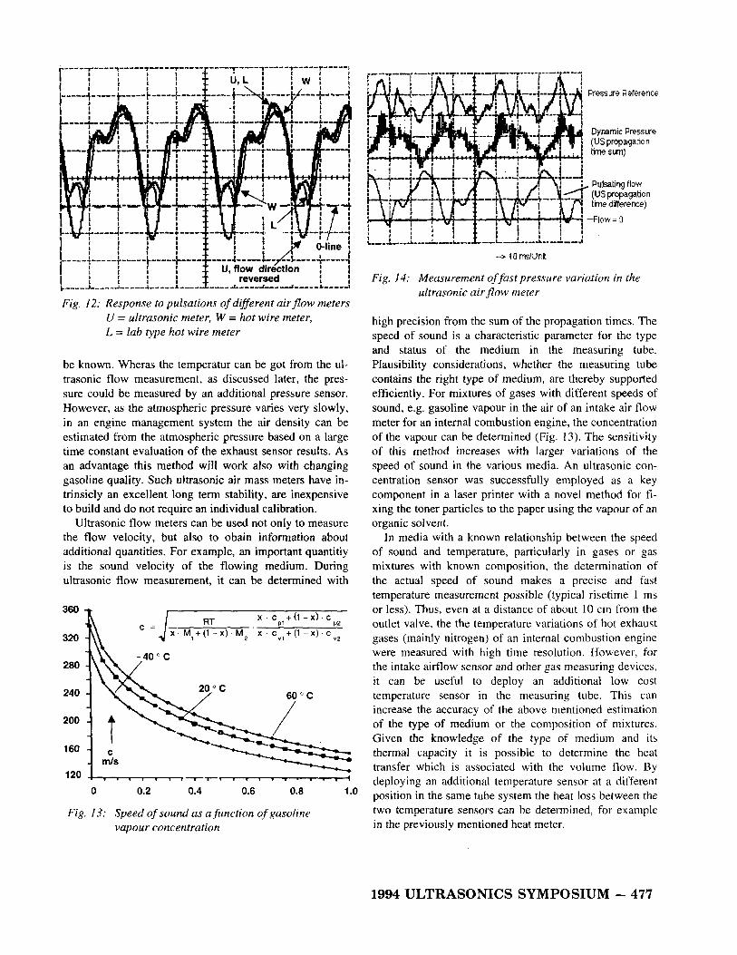
Ultrasonic flow meters can be used not only to measure the flow velocity, but also to obain information about additional quantities. For example, an important quantitiy is the sound velocity of the flowing medium. During ultrasonic flow measurement, it can be determined with
360
320
280
240
200
1 60
120
x c + d - X ) c
x M,+(1 - x ) M2 X C , , + ( I - X ) C v 2
0 0.2 0.4 0.6 0.8 1 .o
Fig. 13: Speed of sound as a function of gasoline vapour concentration
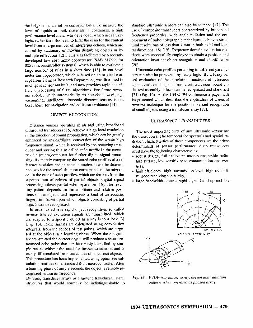
Pressure Reference
Dynamic Pressure (US propagation time sun)
--> 10 ms/Unit
Fig. 14: Measurement of fast pressure variation in the ultrasonic airflow meter
high precision from the sum of the propagation times. The speed of sound is a characteristic parameter for the type and status of the medium in the measuring tube. Plausibility considerations, whether the measuring tube contains the right type of medium, are thereby supported efficiently. For mixtures of gases with different speeds of sound, e.g. gasoline vapour in the air of an intake air flow meter for an internal combustion engine, the concentration of the vapour can be determined (Fig. 13). The sensitivity of this method increases with larger variations of the speed of sound in the various media. An ultrasonic con- centration sensor was successfully employed as a key component in a laser printer with a novel method for f i - xing the toner particles to the paper using the vapour of an organic solvent.
In media with a known relationship between the speed of sound and temperature, particularly in gases or gas mixtures with known composition, the determination of the actual speed of sound makes a precise and fast temperature measurement possible (typical risetime 1 ms or less). Thus, even at a distance of about 10 cm from the outlet valve, the the temperature variations of hot exhaust gases (mainly nitrogen) of an internal combustion engine were measured with high time resolution. However, for the intake airflow sensor and other gas measuring devices, it can be useful to deploy an additional low cost temperature sensor in the measuring tube. This can increase the accuracy of the above mentioned estimation of the type of medium or the composition of mixtures. Given the knowledge of the type of medium and its thermal capacity it is possible to determine the heat transfer which is associated with the volume flow. By deploying an additional temperature sensor at a different position in the same tube system the heat loss between the two temperature sensors can be determined, for example in the previously mentioned heat meter.
1994 ULTRASONICS SYMPOSIUM - 477

Fig. 15: Ultrasonic presence detectors for operation frequencies of 60-400 kHz
In gases, pressure has very little influence on the speed of sound. However, fast adiabatic pressure variations are associated with temperature variations and therefore accessible for the ultrasonic measurement. Fig. 14 shows the results of such a measurement of pulsating air flow in an ultrasonic air mass sensor compared to a conventional pressure sensor.
INTELLIGENT DISTANCE SENSORS
Ultrasonic Distance sensors are used to detect the pre- sence and distance of objects. They do so by evaluating the echo of a transmitted pulse with concern to its travel time. Time dependent control of sensitivity is used to
I
Fig. 16: Fast object recognition with inverse fitered ul- trasonic signals. a ) transmitted signal, b) re- sponse from right object, c) reponse from wrong object.
compensate the distance dependency of the echo amplitu- de, while different reflection properties are compensated by an automatic gain control, which holds the average echo amplitude constant. Echo amplitude therefore has very little influence on the accuracy of the distance measurement, provided the signal to noise ratio is not very low.
By considering whether the echo has been received wit- hin a time window, i.e. a time interval, which can be pre- set by the user, the distance range is given in which the sensor responds to the presence of an object [ l I ] . Accor- dingly, two or more different time windows can be defi- ned and their results, i.e. whether an object is present (lo- gical high state H) or not (logical low state L), can be ana- lyzed by Boolean operations. Using this technique, inter- ference can be supressed and relevant objects are monito- red more reliably. Fig. 15 shows a variety of such ultraso- nic presence sensors with different operation frequencies, which are designed for different distance range and diffe- rent local resolution. Such sensors are employed in the au- tomation of industrial processes as well as in traffic con- trol systems; for example, to monitor, whether car parking places are occupied. Ultrasonic distance meters are used for the measurement of the filling level in containers or
Fig. 17: Recognition of defects in a printed circuit by fuzzy evaluation of correlation functions.
478 - 1994 ULTRASONICS SYMPOSIUM
the height of material on conveyor belts. To measure the level of liquids or bulk materials in containers, a high performance level meter was developed, which uses Fuzzy logic, rather than Boolean, to filter the echo for the content level from a large number of interfering echoes, which are caused by stationary or moving disturbing objects or by multiple reflections [12]. This was facilitated by a recently developed low cost fuzzy coprozessor (SAB 81C99, for 8051 microcontroller systems), which is able to evaluate a large number of rules in a short time [13]. In our level meter this coprocessor, which is based on an original con- cept from Siemens Research Department, was first used in intelligent sensor analysis, and now provides rapid and ef- ficient processing of fuzzy algorithms. For future perso- nal robots, which automatically do household work, e.g. vacuuming, intelligent ultrasonic distance sensors is the best choice for navigation and collision avoidance [ 141.
OBJECT RECOGNITION
Distance sensors operating in air and using broadband ultrasound transducers [ 151 achieve a high local resolution in the direction of sound propagation, which can be greatly enhanced by analog/digital conversion of the whole high frequency signal, which is received by the receiving trans- ducer and storing this so called echo profile in the memo- ry of a (micro)computer for further digital signal proces- sing. By merely comparing the stored echo profiles of a re- ference situation and an actual situation, i t can be detenni- ned, wether the actual situation corresponds to the referen- ce. In the case of echo profiles, which are derived from the superposition of echoes of partial objects, digital signal processing allows partial echo separation [ 161. The resul- ting pattern depends on the amplitude and relative posi- tions of the objects and represents a kind of an acoustic fingerprint, based upon which objects consisting of partial objects can be recognized.
In order to achieve rapid object recognition, so called inverse filtered excitation signals are transmitted, which are adapted to a specific object as a key is to a lock [3] (Fig. 16). These signals are calculated using convolution integrals, from the echoes of test pulses, which are targe- ted at the object in a learning phase. When these signals are transmitted the correct object will produce a short pro- nounced echo pulse that can be rapidly identified by sim- ple means without the need for further calculation and is easily differentiated from the echoes of "incorrect objects". This procedure has been implemented using optimized cal- culation routines on a standard 8-bit microcontroller. After a learning phase of only 3 seconds the object is reliably re- cognized within milliseconds. By using transducer arrays or a moving transducer, lateral structures that would normally be indistinguishable to
standard ultrasonic sensors can also be scanned [17]. The use of composite transducers characterized by broadband frequency properties, wide angle radiation and the em- ployment of pulse holographic techniques, achieves struc- tural resolutions of less than 1 mm in both axial and late- ral directions [ 181 [ 191. Frequency domain evaluation me- thods were successfully employed to obtain a position and orientation invariant object recognition and classification r201.
Ultrasonic echo profiles pertaining to different parame- ters can also be processed by fuzzy logic. By a fuzzy ba- sed evaluation of the correlation functions of reference signals and actual signals from a printed circuit board un- der test assembly defects can be recognized and classified [21] (Fig. 16). At the UFFC '94 conference a paper will be presented which describes the application of a neural network technique for the position invariant recognition of small objects using a transducer array [22].
ULTRASONIC TRANSDUCERS
The most important parts of any ultrasonic sensor are the transducers. The temporal (or spectral) and spatial ra- diation characteristics of these components are the prime determinants of sensor performance. Such transducers must have the following characteristics:
robust design, full enclosure smooth and stable radia- ting surface, low sensitivity to contamination and wet- ness, high efficiency, high transmission level, high reliabili- ty, good receiving sensitivity, large bandwidth ensures rapid signal build-up and fast
- 20 0
Fig. 18: PVDF-transducer array, design and radiation pattern, when operated as phased array
1994 ULTRASONICS SYMPOSIUM - 479

/ v-n. Fig. 19: High directivi9 ultrasonic transducer: radiation
pattern and design principle. 1 ) matching layer, 2 ) piezo-ceramic, 3 ) metal ring, 4 ) main lobe
decay after transmission stop and provids high local resolution, application specific directional characteristics with good suppression of side lobes. For operation in air, no single transducer fulfills all of
the above mentioned requirements optimally. Electrostatic foil transducers which have excellent acoustic properties in air, are of limited use because of their sensitivity to wet- ness and contamination. Transducer made from a piezoe- lectric PVDF-foil 1231 have also a broad bandwidth and a lower impedance than electrostatic transducers. PVDF- transducers consist of a part of a cylindrical wall and transform vibrations which are excited by the transversal piezo-effect to a large area displacement. These can easily configurated as transducer arrays (Fig. 18) which can be operated as phased arrays with electronical steering of the radiation pattern.
Transducers made from solid piezoceramic or magneto- strictive materials are robust, but due to the high acoustic impedance of these materials are principally inefficient for the operation in gases. The acoustic matching of these so- lid materials to particular gasses can be substantially im-proved by applying transforming layers of materials with low acoustic impedance as in the case of the so-called RU transducers (Fig. 17). These transducers [24] have a high directivity and can be designed in the 30-500 kHz rangeand at a frequency, which is predetermined by their indivi- dual geometrical dimensions. They are ideal as high speedindustrial sensors for measuring distances, level heightsand similar parameters. Such transducers are also suitablefor ultrasonic air or gas flow velocity measuring devices,for example in an automotive intake air mass meter. Transducers with rubber-like materials as matching layersare realized with good efficiency for airborne ultrasound
Fig. 20: L2QZ-Transducer
in frequencies up to lMHz [25]. Promising materials for the acoustic matching to air and
gases are aerogels which have a relatively low density (300 ... 2000 Kg/m3). By the use of aerogels which can be described as gels in which air replaces the water as a second matching layer transducers of the previously des- cribed type were improved considerably in their efficien- cyhandwidth-ratio. The instability of aerogels in the pre- sence of water were successfully eliminated [26] but furt- her research is to be done, to obtain aerogels which are al- so stable in the presence of organic solvents.
Using a stack of thin piezoceramic sheets and plastic material in between robust transducers for airborne ultra- sound were constructed. These so called L2QZ-transdu- cers (low Q-factor, low Z) show a relatively high band- width allowing short ultrasonic signals to be transmitted and received, providing a good local resolution [17].
CONCLUSIONS
Evidence has been given that a lot of different ultrasonic sensors can be developed for operation in air. By exam- ples, it was shown that for many important applications these sensors are a good choice. Topics for future research and development work comprise:
advanced physical models and algorithms to improve the sensor functionality and accuracy, application of digital signal processors to provide impro- ved sensor signal evaluation at competitive costs, extension of the intelligent ultrasonic sensor concept for- ming a decentralized multiple sensor system with bus communication capabilities. The application potential for ultrasonic sensors is appa-
rent in many areas, for example in private housing, health care, environment protection, traffic and automotive con- trol or industrial process control. In the future, ultrasonic sensors with improved functionality will continue to ex- pand their applications.
480 - 1994 ULTRASONICS SYMPOSIUM

REFERENCES
Bergmann, L.: Der Ultraschall und seine Anwen- dungen in Wissenschafi und Technik. 6. ed. Stutt- gart, Hirzel-Verlag 1954. Lynnworth, L.C.: Ultrasonic Measurement for Pro- cess Control. Academic Press Inc. (1989), ISBN 0- 12-460585-0. Magori, V.: Signal Processing for Smart Ultrasonic Sensors, Proc. 3rd Annual European Computer Con- ference (l989), pp.(3-21) - (3-26). Trankler, H. R.: Sensorspezifische Mej'signalverar- beitung, NTG-Fachber. 93 (1986) p. 301 ff. Kaulfersch, H.; Migori, V.: Korrelationsmessung von Stromungsgeschwindigkeiten rnit verbessertem Ultraschall-Verfahren. German Patent 3732834, filed 29.9.87 v. Jena, A.; Migori, V.: Progress in Vortex- Sensoring of Automotive Intake Air Flow. Proc. ISATA 18th Internat. Symp. Automot. Technol. & Automat. (1988), pp. 88102/1-9. Mc Shane, J.L.: Ultrasonic Flowmeter. Flow. Vol. 1, Part 2. Edited by R.E. Wendt, Pittsburg (1974), pp. 897-916. v. Jena, A.: Ultraschall-Durch~u~-Sensor fur die Warmemengenmessung. VDI-Ber. 509 (1 984), pp. 39-42. v. Jena, A.; MBgori, V.; RuBwurm, W.: Ultrasound Gas Flow Meter for Household Application. Sensors andActuators A Vol. 37-38 (1993), pp. 135-140. v. Jena A.; Migori V.: Die Ansaugstromung von Kfz-Motoren mit Ultraschall messen. Feinwerk- und MeBtechnik 100 (1992), pp. 95 ff. Migori, V.; Walker, H.: Ultrasonic Presence Sen- sors with Wide Range and High Local Resolution. IEEE Transactions UFFC Vol. UFFC-34 (1987), pp. 202-2 1 1. Kroemer, N. et al.: Ultraschall-Distanzsensor mit Fuzzy-Auswertung. KongreRband I1 Sensor '93 (1993). pp. 113-121 Eichfeld, H.; Kunemund, T.; Klimke, M: A 8 bit Co- processor for fuzzy Control. Proc. ISSCC '93 (1 993), pp. 180- 18 1, 286. Rencken, W.D. et al.: Autonomous low-cost Mobile Robots for Complex Non-production Environments, 1 st IFAC Internat. Workshop on Intelligent Autono- mous Vehicles, Univ. of Southampton, U.K. (1993). pp.31-36.
[ 151 Kleinschmidt, P.; MBgori, V.: US Robotic-Sensors for Exact Short Range Distance Measurement and Object fdentzjkation. Proc. IEEE Ultrasonics Symp. (1985), pp. 457-462.
[ 161 Bernst, T.; Loschberger, J.; MBgori, V.: Moderne Velfahren der Signalverarbeitung bei Ultraschall- Robotik-Sensoren. NTG-Fachberichte 93 (1986), pp. 253-263.
1171 Schoenwald, J.S.; Martin, J.A.; Ahlberg, L.A.: Acou- stic Scanning for Robotic Range Sensing and Object Pattern Recognition. Proc. IEEE '82 Ultrasonics Symp. (1982), pp, 945-949.
[ 181 Loschberger J.; Magori V.: Ultrasonic Robotic Sen- sors with Lateral Resolution, IEEE '88 Ultrasonics Symposium (1988), pp. 547 ff.
[ 191 Knoll, A.C.: Ultrasonic Holography Techniques for Localizing and Imaging Solid Objects. IEEE Trans. Robot. & Automation, Vol. 7 (4), (1991)
[20] Lach, M.; Ermert, H.: Object Recognition Using an Ultrasonic Sensor System. Acoust. Imaging 19 (1992), pp. 957-962.
[21] Vossiek, M. et al.: Intelligente Sensorsignalverar- beitung durch Kombination von Fuzzy-Logik mit klassischer Signalvorverarbeitung am Beispiel eines Luftultraschallsystems zur Platinenbestuckungskon- trolle. VDE-Fachtagung Techn. Anwendung < Fuz- zy-Systemen, Dortmund (1992), pp. 71-80. Vossiek, M.; MBgori, V.; Ermert, H.: An Ultrasonic Multielement Sensor System f o r Position Invariant Object Identification. Proc. IEEE UFFC '94 Sympo- sium, (prepared) Manthey, W.; Kroemer, N.; MBgori, V.: Ultrasonic 25. Meas. Sci. Technol.. 3 (1992) pp. 294-261, Kleinschmidt, P.; MBgori, V.: Ultrasonic Remote Sensors for Noncontact Object Detection. Siemens Forschungs- und Entwicklungsberichte 10, (198l), pp. 110-118. Yano, T.; Tone, M.; Fukumoto, A: Range Finding and Surface Characterization Using High-Frequen- cy Air Transducers, IEEE Trans. UFFC (1987), pp. 232 ff. Gerlach, R. et al.: Modified Si02 aerogels as acoustic impedance matching layers in ultrasonic devices. J. Non-Crystaline Solids 145 (1992), pp. 227-232.
1994 ULTRASONICS SYMPOSIUM - 481