Embed Size (px)
Citation preview

Ultrasonic Gas Meters for Industrial and Commercial
Applications
Ohio Gas AssociationTechnical SeminarMarch 27-28,2014

Objectives
Technology
Operation
Benefits
Applications
Approvals and Standards
Products

Ultrasonic: Basics
Sound waves
Acoustic (audible sound)
20 Hz to 20,000 Hz
Ultrasonic
Generally above 20,000 Hz
Time of Flight
Velocity is determined based upon transit time of sound waves

Fundamentals of Ultrasonic
Measurement
Because of the larger flowing diameter, the profile of the gas can take various shapes. Therefore, multiple path measurements are required to determine the average gas velocity.
Multi Path – High Flow

Fundamentals of Ultrasonic
Measurement
Ultrasonic pulses are produced with - and against - the gas stream. Pulses flowing with the gas velocity speed up; pulses flowing against the gas velocity slow down. The difference is used to calculate the gas speed or velocity within the known area.
Single Path – Low Flow

Time of Flight Principles
Piezoelectric transducers generate and detect waves
Waves travel at the speed of sound of the moving fluid
Velocity of gas is determined from the transit time of generated sound waves
Sampling system: Spot measurement repeated at intervals averaging 2 seconds
Volume (ft3) = Velocity (fps) X cross sectional Area of flow tube (ft2) X sample Time (s)

Ultrasonic Meter Schematic
Flow in Flow out
Transducer 1 Transducer 2
V
dl
C + V C - V

Transducer Schematic
Backing
Piezoelectric Element
Quarter Wave Plate
ElectricalLeads
Cap

Ceramic Crystal Operation
A voltage difference across the faces of the ceramic causes it to oscillate SONIX meters ~ 160 kHz.
Matching layer amplifies movement, 20 times, and provides an efficient transfer of energy

Operation
L2L2
Electronics
L1
T2T1
TL
C V2
T
L
C V1
V
L
T T
2
1 1
2 1
so
VL
xT T
T T
2
1 2
1 2
T1
T2= Time of upstream firing C = Speed of sound in gas
= Time of downstream firing V = Velocity of the gas

87654 155
INLET AREA OUTLET AREA

87654 155
INLET AREA OUTLET AREA

87654 155
INLET AREA OUTLET AREA

87654 155
INLET AREA OUTLET AREA

87654 155
INLET AREA OUTLET AREA

87654 155
INLET AREA OUTLET AREA

87654 155
INLET AREA OUTLET AREA

87654 155
INLET AREA OUTLET AREA

87654 155
INLET AREA OUTLET AREA

87654 155
INLET AREA OUTLET AREA

87654 155
INLET AREA OUTLET AREA

87654 155
INLET AREA OUTLET AREA

87654 155
INLET AREA OUTLET AREA

87654 155
INLET AREA OUTLET AREA

87654 155
INLET AREA OUTLET AREA

87654 155
INLET AREA OUTLET AREA

87654 155
INLET AREA OUTLET AREA

87654 156
INLET AREA OUTLET AREA

Ultrasonic Timing
Time is measured two ways
Course measurement - number of clock pulses to receive pulse
Fine measurement - calculated by the phase of the final pulse
The meter has to measure the “time of flight” of the ultrasonic pulse in nanoseconds (10-9 sec) to achieve acceptable volume accuracy
(0.000000001)

Ultrasonic Timing
Phase Change
Clock
Pulses
TransmitSignal
Receive
Signal
PhaseShifted
Signal
Figure 4. The relationship between the transmitted and received
ultrasonic signals and the phase shift or delay time.
= 0t0
t1

Speed of Sound Determination
L2L2
Electronics
L1
T2T1
TL
C V2
T
L
C V1
V
L
T T
2
1 1
2 1
so
VL
xT T
T T
2
1 2
1 2
T1
T2= Time of upstream firing C = Speed of sound in gas
= Time of downstream firing V = Velocity of the gas

Basic Operation Principles SONIX600/880
Main
Transducers

SONIX2000
4 Main
Transducers

SOS TransducerTransducer
Speed of
sound box
Improves Meter Accuracy
Diagnosis Meter Health
Provides Tamper and Theft Detection

Flow SOS
Transducer
Basic Operation Principles SONIX600/880

SONIX2000
SOS
Transducer
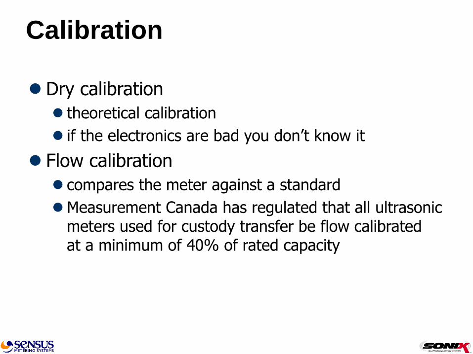
Calibration
Dry calibration
theoretical calibration
if the electronics are bad you don’t know it
Flow calibration
compares the meter against a standard
Measurement Canada has regulated that all ultrasonic meters used for custody transfer be flow calibrated at a minimum of 40% of rated capacity

Industry standard provers -- sonic nozzle--
A known volume is passed through the meter at two flow rates
Errors are averaged and calibration value stored into EEPROM
Recheck flow measurement at all flow rates
Meter identification and calibration are locked into memory
Proving

Snap
North American Services Group
130 Allatoona Dam Road
Cartersville, GA 30120
ATTN: Greg Germ
Phone: 770-607-7272
Approximate $885 upgrade
Measurement Systems
6217 Stoney Hill Road
New Hope, PA 18938
ATTN: Harry Deutsch
Can-Tronics
16 Harlowe Road, Unit 3
Hamilton, Ontario, CANADA L8W 3R6
ATTN: Richard Juszczak
Phone: 905-574-6488
Energy Economics
109 South Street SE
Dodge Center, MN 55927
Phone: 800-733-2557
SONIX Compatible Provers

SONIX880
Initial Factors
Speed 117 Spread 0
-0.87
0.68
1.55
-2.00
-1.50
-1.00
-0.50
0.00
0.50
1.00
1.50
2.00
0 100 200 300 400 500 600 7 00 800 900 1000
Flowrate (CFH)
% E
rr
or
Open Check Spread

SONIX880
Final Factors
Speed 125 Spread 25
0.080.02 -0.06
-2.00
-1.50
-1.00
-0.50
0.00
0.50
1.00
1.50
2.00
0 100 200 300 400 500 600 7 00 800 900 1000
Flowrate (CFH)
% E
rr
or
Open Check Spread
Speed and Spread Calibration Factors Calculated
and Changed with a simple push of a button.

SONIX600 and SONIX880 In Service
Performance
•990 meters from 5 different utilities
•Meters produced from 2002 thru 2007
•Average mileage was 404,600 cf
•Maximum registration was 3,845,900 cf in 5 years

3.02.52.01.51.00.50.0-0.5-1.0-1.5-2.0-2.5-3.0
LSL Target USL
LSL -2
Target 0
USL 2
Sample Mean -0.0250355
Sample N 991
StDev 0.488732
Process Data
% < LSL 0.20
% > USL 0.00
% Total 0.20
Observed Performance
Histogram of Open

3.02.52.01.51.00.50.0-0.5-1.0-1.5-2.0-2.5-3.0
LSL Target USL
LSL -2
Target 0
USL 2
Sample Mean 0.119947
Sample N 990
StDev 0.382554
Process Data
% < LSL 0.10
% > USL 0.10
% Total 0.20
Observed Performance
Histogram of Check

Ultrasonic Meter Benefits
No moving parts
Accurate measurement including very low flows
Compact size
Can fit existing meter installations
Long term stability and accuracy
Eliminates sampling plans
Health Check
Diagnoses meter health, accuracy as well as operating environment.

Health Check Benefits
Flag
Letter displayed on LCD
Diagnostic
Details obtained by interrogating the meter
Problem Counter
Internal count of number of occurrences of operating events

‘A’ Flag - Catastrophic Failure
EEPROM Checksum Failure
RAM index checksum check for match with EEPROM
‘A’ Flag is not cleared by power or diagnostic reset
Meter stops working and needs to be returned to the factory
Health Check Benefits

‘b’ Flag - Major Event
Significant reverse or negative flow
Power reset
Fast sample mode entered
EEPROM reboot command
Air in meter
‘b’ Flag may indicate potential tampering
Meter continues to operate accurately
Health Check Benefits

‘C’ Flag - Major Operational Problem
Measurement problems occurring > 128 times per day
Unsatisfactory readings
Speed of sound (SOS) out of range
Rate of change of SOS out of range
Date of first and last occurrence, and number of occurrences recorded
Diagnostic & power reset clears records
Meter continues to operate accurately
Health Check Benefits

‘r’ Flag – Battery Life Warning
An ‘r’ Flag will indicate that the battery has been installed for 9.5 years of operation.
Suggests battery change out at a convenient time.
Health Check Benefits

‘F’ Flag – Battery Life Warning
An ‘F’ Flag will indicate that the battery has been installed for 11.0 years of operation.
Suggests battery change out as soon as possible.
Battery life is warranted for 10 years
Health Check Benefits

Customized Diagnostics

Customized Diagnostics

SONIX600 – Industrial and Commercial
•600 to 1130 Cubic Feet per Hour
•20 psig Maximum Operating Pressure
SONIX880 – Industrial and Commercial
•880 to 1625 Cubic Feet per Hour
•20 psig Maximum Operating Pressure
Obviously smaller and lighter with
two centuries of technological
advancements.

Size it up

Weight, Freight and Space Benefits
18 - #750 meters = 900 pounds
64 - SONIX880 meters = 720 pounds
(355% more meters at 80% of the weight)


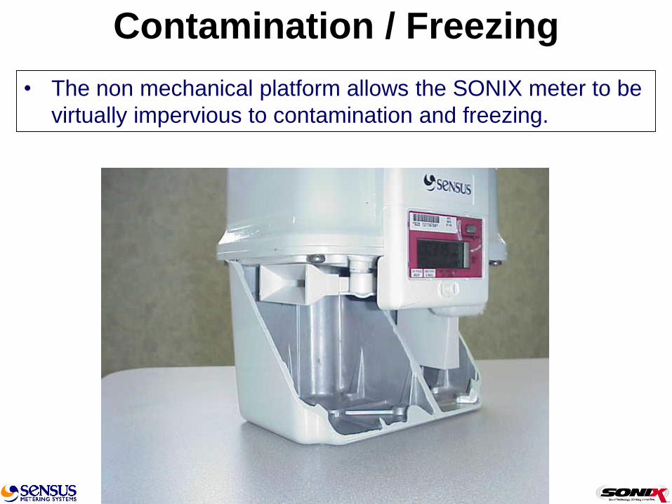
Contamination / Freezing
• The non mechanical platform allows the SONIX meter to be
virtually impervious to contamination and freezing.

Contamination / Freezing
• The flow tube inlet is positioned high in the body cavity to
virtually eliminate the entrance of foreign material and
liquids. This allows the body to act as a sump or drip leg.

Contamination / Freezing
• The body inlet chamber has a cast boss that can be drilled
and tapped for an optional drain valve to remove liquids and
debris in sever applications.

Well Head Measurement


Meter Set Benefits


Reduced Cost of Installation
Standard #800 Class Installation
Parts
10% reduction in fittings
Real Savings is in the labor – 75%
Two men – 1 hours
One man – ½ hour
One prefabricated set, Two connections
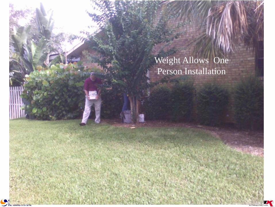
Weight Allows One
Person Installation

...versus Diaphragm Meters
Significantly reduces space requirements
Lighter Weight
Standardized installation costs under wide range of flow capacities
(0.21 – 3,800 scfh)
Temperature correction (+/-1.0%)
Programmable fixed factor pressure correction
Positively records potential “theft of service”
60 Day Data Log Standard
15 year warranty

Off-Set Swivels for Replacements
Swap previously installed diaphragm meters that had 11” center to center hubs.
Black Iron or Galvanized
2 ½” Offset on each side
1 ½” piping
45 Lt Swivel/Nut
Meter & Swivel Set Kit

Meter Bar for New Installations

Standards & Approvals
US
A.G.A. Distribution Measurement Committee task group working on Technical Note for residential and commercial meters
A.G.A. Report #9
Canada
PS-G-06-E
OIML
In working group stage

Canada: PS-G-06-E
Provisional standard released in March 1998
Applicable for all ultrasonic meters used for custody transfer
Key features:
Rangeability minimum of 10:1
Accuracy of better than 1.0%
Meters must be flow calibrated

SONIX600 – Industrial and Commercial
•600 CFH at ½ “ W.C. Differential
•1130 CFH at 2” W.C. Differential
SONIX880 – Industrial and Commercial
•880 CFH at ½ “ W.C. Differential
•1625 CFH at 2“ W.C. Differential
SONIX2000 – Industrial and Commercial
•2000 CFH at ½ “ W.C. Differential
•3000 CFH at 1.3“ W.C. Differential
74

Live Pressure Correction and 60 days of
hourly data log

SONIX2000

SONIX2000

Available Commercial Meters
Sensus Sonix 600 - 600/1130 cfh – 20 psig MAOP
Sensus Sonix 880 - 880/1625 cfh – 20 psig MAOP
Sensus Sonix 2000 - 2000/3000 cfh – 60 psig MAOP
Approved for Custody Transfer by Measurement Canada and various State Commissions

Questions?