Embed Size (px)
Citation preview

Ultrasonic flow measurement in liquid metal models of continuous steel casting
Klaus TIMMEL, Thomas WONDRAK, Sven FRANKE, Sven ECKERT Helmholtz-Zentrum Dresden-Rossendorf (HZDR), P.O. Box 510119, 01314 Dresden, GERMANY
Model experiments with low melting point liquid metals are an important tool to investigate the flow structure
and related transport processes in melt flows relevant for metallurgical applications. One very important
industrial process is the continuous casting of steel. But there exist almost no measurement data of the inner mold
flow from real casting plants and there are no satisfying measurement techniques available for those harsh
conditions. By this, e.g. a detailed understanding of the action of electromagnetic brakes on the complex flow is
missing. Therefore we built model experiments for the continuous casting process of steel by using low melting
liquid metals and investigated the mold flow under different conditions. The main value of cold metal laboratory
experiments consists in the capabilities to obtain quantitative flow measurements by ultrasonic flow
measurements with a reasonable spatial and temporal resolution. Standard transducers were used at the model
operating at room temperature with the eutectic alloy of GaInSn. Ultrasonic transducers for high temperatures and
ultrasonic waveguide sensors were used at the big model, which uses the alloy Sn60Bi40 as model liquid and is
operated at temperatures of 200-350 °C. Results from the mold flow measurement will be presented, showing the
effect of a static magnetic field on the flow structure. It turned out, that the magnetic field can locally accelerate
the flow, contrary to the expected action as a brake. The ultrasonic velocity measurement data were further used
for validation and for comparison with other measurement techniques at the model experiment.
Keywords: Continuous casting of steel, electro-magnetic flow control, liquid metal models, applied
Ultrasonic Doppler Velocimetry, ultrasonic wave-guides, high temperature transducers
1. Introduction
The persistent effort to achieve a better product quality
and higher productivity of the continuous casting of steel
implies the high importance of powerful capabilities to
control the flow in tundish and mold, and the initial
solidification in the mold. Numerous sophisticated
numerical simulations concerned with the metal flow
during the casting process need a fundamental
experimental validation. The use of water models has the
advantage to save expenses and to be able to apply a
number of well-proofed measuring methods. However, a
generalization of these results to liquid metal flows has to
be considered as questionable because the realistic values
of flow parameters (Re, Pr, Gr, Ha, etc.) are difficult to
meet. In many cases, for instance liquid metal flows with
strong temperature gradients, with an additional gaseous
phase or under the influence of electromagnetic fields,
the flow phenomena cannot reasonably be modelled by
means of water experiments.
The application of electromagnetic fields provides a
considerable potential to control the fluid flow in the
mold and to influence the solidification in the strand.
First strategies for EM applications in steel casting were
mainly guided by simplified pictures of the magnetic
field impact on the global flow field. Many numerical
investigations have been reported until now to improve
the understanding of the magnetic field influence on the
mold flow (see for instance [2-5]). However, the problem
has to be considered as challenging because of the
complex geometry, the highly turbulent flow, and
specific peculiarities occurring in case of MHD
turbulence. Obviously, a validation of the numerical
predictions by liquid metal experiments is indispensable.
However, related experimental studies are rather scarce
until now. Several plant trials were carried out [6, 7] to
test the efficiencies of electromagnetic brakes in the real
casting process. Because of the lack of suitable
measuring techniques for liquid steel at 1500 °C such
trials cannot provide any reliable knowledge about the
magnetic field effect on the flow in the mold. First model
experiments employing simplified mercury models have
been reported by Japanese [8, 9] and French [10] groups.
With our work we want to continue the strategy of cold
metal models. The main value of such cold metal
laboratory experiments consists in the capabilities to
obtain quantitative flow measurements with a reasonable
spatial and temporal resolution. The key measurement
technique for flow characterization in our experiments is
the Ultrasonic Doppler Velocimetry. It reveals the mold
flow structure under different casting conditions and
allows a validation of new liquid measurement
techniques, like the Contactless Inductive Flow
Tomography [11,12].
2. Experimental facilities
The experimental program of the LIMMCAST facilities
at HZDR aims to model the essential features of the flow
field in the continuous casting of steel. Basically, these
are the flow fields in the tundish, in the submerged entry
nozzle (SEN) and in the mold cavity, the complex two-
phase flow in SEN and mold due to argon injection as
well as the effect of electromagnetic actuators at the
mold. For this purpose, there have been build three
experimental facilities dealing with the modelling of the
continuous casting process.
A photograph showing an overall view of the
10th International Symposium on Ultrasonic Doppler Methods for Fluid Mechanics and Fluid Engineering Tokyo Japan (28-30. Sep., 2016)
17

LIMMCAST facility is displayed in Fig. 1. All
components are made of stainless steel, including the
tundish, the SEN and the mold. The low melting point
alloy Sn60Bi40 is used as model liquid. The liquidus
temperature of 170°C allows for an operation of the
facility in a temperature range between 200 and 350°C.
The schematic sketch in Fig. 1 illustrates the setup
comprising two test sections. A simple pipe test section is
used for general testing of measurement techniques for
hot liquid metals. The continuous casting strand contains
the models of a tundish, a SEN and a mold. The test
sections are filled with liquid metal from the storage tank
by pressurized Argon. An unused test section can be
sealed by valves (not displayed in the sketch). When the
loop is filled, the melt is driven by an induction pump
through the corresponding test section.
The investigations on continuous casting will be
explicitly focused on the behavior of the isothermal melt
flow. Argon gas bubbles can be injected with tunable
flow rates through the stopper rod into the SEN resulting
in a two-phase flow inside the nozzle and the mold. Pipe
connections with flanges are realized at various locations
within the loop allowing in principal a replacement of the
particular components, which gives us a flexibility to
modify the flow geometries for miscellaneous
requirements.
Fig. 1: LIMMCAST – large scale (250 °C) liquid metal
experiment for continuous flow measurement in tundish, SEN
and mold (left) and a schematic setup (right).
Fig. 2 shows the small-scale setup Mini-LIMMCAST,
which is operated with the eutectic alloy GaInSn as
model fluid. The experiments at this setup allow for flow
measurements at room temperature (Liquidus
temperature of the alloy is 10°C) and gained in valuable
experiences for the detailed design of the larger
LIMMCAST facility during its build-up.
Fig. 2: Mini-LIMMCAST – small scale acrylic glass model for
experimental flow investigations at room temperature using
GaInSn (left) and a sketch of the operation principle (right).
The results of this setup were gained at a discontinuous
operation. The melt was conveyed from the storage tank
into the tundish by an induction pump. When the tundish
was filled, the stopper rod was pulled and the melt was
flowing through the SEN into the mold. From the mold
the melt is flowing over a dam back into the storage tank.
Meanwhile, a continuous operation of this setup is also
possible, but the quality of ultrasonic signal for velocity
measurements is degrading in this operation mode due to
increased damping of the ultrasonic signal.
The third setup, the X-LIMMCAST, is specialized in
visualization of liquid metal – Argon two-phase flows by
X-ray imaging. It will be therefore not considered in this
paper.
Velocity measurements by the Ultrasound Doppler
Velocimetry were done at LIMMCAST and Mini-
LIMMCAST by using the devices DOP2000 or
DOP3010 from Signal Processing. Different kinds of
transducers were applied, like standard ones, high
temperature transducers and transducers equipped with a
wave-guide. The quantity of operated transducers in
multiplexer mode ranged from two to the maximum
possible of ten. The next section will give an overview on
the measurement conditions and present some
measurement results.
3. Experimental results
3.1 Mini-LIMMCAST – room temperature
Previous experiments showed a dramatic influence of a
static magnetic field on the liquid metal flow in the mold
[13]. Low frequency oscillations of the horizontal jet
flow were detected as well as a local acceleration of the
flow. The jet is deflected upwards by the static magnetic
field resulting in a strong upwards flow near the narrow
wall. This strong upward flow was measured now in the
vertical velocities with the Ultrasonic-Doppler-
Velocimetry (UDV) [14]. Two standard transducers with
an acoustic diameter of 5 mm and an ultrasonic frequency
of 4 MHz were used (TR0405LS).
During the measurement, the two transducers were in
direct contact with the liquid metal. They dipped from top
through the free surface into the melt. The challenge was
the lift of the free surface of several centimeters between
the rest and the running condition. The transducers were
floating above the free surface at the start of the
experiment, where the melt is at a rest. When the
experiment and melt flow starts, the liquid metal level in
the mold rises due to the hydrodynamic resistance in the
whole outflow pipe as the outflow is driven only by
gravity. Oxides at the free surface laid themselves on the
transducers face and blocked the acoustic coupling into
the liquid metal. A gadget with a covering plate had to
protect the transducers faces and had to be pivoted away
once the liquid metal level rose above the transducers
contact face. With this gadget it was than possible to
measure the vertical flow in the mold from the top. A
measurement in vertical direction from the bottom
through the bottom wall was not possible because of the
high thickness of the bottom wall, the great measurement
distance from the bottom towards the jet flow and the
18
settling of particles / impurities at the bottom which block
the ultrasonic coupling into the melt.
The two ultrasonic transducers (labeled with “US” in Fig.
3) were mounted one in each mold half symmetrically
with respect to the mid-plane or the SEN, respectively.
The mean vertical velocity profile along the narrow mold
wall recorded with this configuration is shown in Fig. 3.
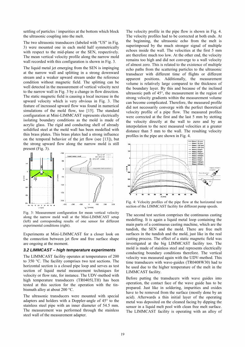
The liquid metal jet emerging from the SEN is impinging
at the narrow wall and splitting in a strong downward
stream and a weaker upward stream under the reference
condition without magnetic field. The splitting can be
well detected in the measurement of vertical velocity next
to the narrow wall in Fig. 3 by a change in flow direction.
The static magnetic field is causing a local increase in the
upward velocity which is very obvious in Fig. 3. The
feature of increased upward flow was found in numerical
simulations of the mold flow, too [15]. The standard
configuration at Mini-LIMMCAST represents electrically
isolating boundary conditions as the mold is made of
acrylic glass. The rigid and conducting shell of already
solidified steel at the mold wall has been modelled with
thin brass plates. This brass plates had a strong influence
on the temporal behavior of the jet flow (see [13]), but
the strong upward flow along the narrow mold is still
present (Fig. 3).
Fig. 3: Measurement configuration for mean vertical velocity
along the narrow mold wall at the Mini-LIMMCAST setup
(left) and corresponding results of one sensor for different
experimental conditions (right).
Experiments at Mini-LIMMCAST for a closer look on
the connection between jet flow and free surface shape
are ongoing at the moment.
3.2 LIMMCAST – high temperature experiments
The LIMMCAST facility operates at temperatures of 200
to 350 °C. The facility comprises two test sections. The
horizontal section is a closed pipe loop and serves as test
section of liquid metal measurement techniques for
velocity or flow rate, for instance. The UDV-method with
high temperature transducers (TR0405LTH) has been
tested at this section for the operation with the tin-
bismuth alloy at about 200 °C.
The ultrasonic transducers were mounted with special
adapters and holders with a Doppler-angle of 45° to the
stainless steel pipe with an inner diameter of 54.5 mm.
The measurement was performed through the stainless
steel wall of the measurement adapter.
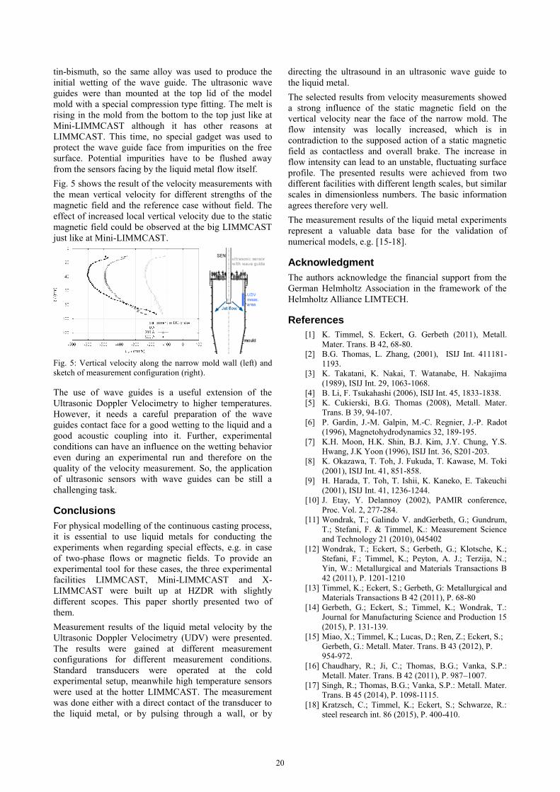
The velocity profile in the pipe flow is shown in Fig. 4.
The velocity profiles had to be corrected at both ends. At
the beginning, the ultrasonic echo from the melt is
superimposed by the much stronger signal of multiple
echoes inside the wall. The velocities at the first 5 mm
are therefore much too low. At the other end, the velocity
remains too high and did not converge to a wall velocity
of almost zero. This is related to the existence of multiple
echo paths from the scattering particles to the ultrasonic
transducer with different time of flights or different
apparent positions. Additionally, the measurement
volume is relatively large compared to the thickness of
the boundary layer. By this and because of the inclined
ultrasonic path of 45°, the measurement in the region of
strong velocity gradients within the measurement volume
can become complicated. Therefore, the measured profile
did not necessarily converge with the perfect theoretical
velocity profile of a pipe flow. The measured profiles
were corrected at the first and the last 5 mm by stetting
the velocity directly at the wall to zero and by an
interpolation to the next measured velocities at a greater
distance than 5 mm to the wall. The resulting velocity
profiles in the pipe are shown in Fig. 4.
Fig. 4: Velocity profiles of the pipe flow at the horizontal test
section of the LIMMCAST facility for different pump speeds.
The second test section comprises the continuous casting
modelling. It is again a liquid metal loop containing the
main parts of a continuous casting machine, which are the
tundish, the SEN and the mold. There are free melt
surfaces in the tundish and the mold, just like in the real
casting process. The effect of a static magnetic field was
investigated at the big LIMMCAST facility too. The
mold is made of stainless steel and represents electrically
conducting boundary conditions therefore. The vertical
velocity was measured again with the UDV-method. This
time transducers with wave-guides (TR0408W30) had to
be used due to the higher temperature of the melt in the
LIMMCAST facility.
Before putting the transducers with wave guides into
operation, the contact face of the wave guide has to be
prepared. Just like in soldering, impurities and oxides
have to be removed from the surface (mostly done by an
acid). Afterwards a thin initial layer of the operating
metal was deposited on the cleaned facing by dipping the
sensor in a liquid melt pool with clean free melt surface.
The LIMMCAST facility is operating with an alloy of
19
tin-bismuth, so the same alloy was used to produce the
initial wetting of the wave guide. The ultrasonic wave
guides were than mounted at the top lid of the model
mold with a special compression type fitting. The melt is
rising in the mold from the bottom to the top just like at
Mini-LIMMCAST although it has other reasons at
LIMMCAST. This time, no special gadget was used to
protect the wave guide face from impurities on the free
surface. Potential impurities have to be flushed away
from the sensors facing by the liquid metal flow itself.
Fig. 5 shows the result of the velocity measurements with
the mean vertical velocity for different strengths of the
magnetic field and the reference case without field. The
effect of increased local vertical velocity due to the static
magnetic field could be observed at the big LIMMCAST
just like at Mini-LIMMCAST.
Fig. 5: Vertical velocity along the narrow mold wall (left) and
sketch of measurement configuration (right).
The use of wave guides is a useful extension of the
Ultrasonic Doppler Velocimetry to higher temperatures.
However, it needs a careful preparation of the wave
guides contact face for a good wetting to the liquid and a
good acoustic coupling into it. Further, experimental
conditions can have an influence on the wetting behavior
even during an experimental run and therefore on the
quality of the velocity measurement. So, the application
of ultrasonic sensors with wave guides can be still a
challenging task.
Conclusions
For physical modelling of the continuous casting process,
it is essential to use liquid metals for conducting the
experiments when regarding special effects, e.g. in case
of two-phase flows or magnetic fields. To provide an
experimental tool for these cases, the three experimental
facilities LIMMCAST, Mini-LIMMCAST and X-
LIMMCAST were built up at HZDR with slightly
different scopes. This paper shortly presented two of
them.
Measurement results of the liquid metal velocity by the
Ultrasonic Doppler Velocimetry (UDV) were presented.
The results were gained at different measurement
configurations for different measurement conditions.
Standard transducers were operated at the cold
experimental setup, meanwhile high temperature sensors
were used at the hotter LIMMCAST. The measurement
was done either with a direct contact of the transducer to
the liquid metal, or by pulsing through a wall, or by
directing the ultrasound in an ultrasonic wave guide to
the liquid metal.
The selected results from velocity measurements showed
a strong influence of the static magnetic field on the
vertical velocity near the face of the narrow mold. The
flow intensity was locally increased, which is in
contradiction to the supposed action of a static magnetic
field as contactless and overall brake. The increase in
flow intensity can lead to an unstable, fluctuating surface
profile. The presented results were achieved from two
different facilities with different length scales, but similar
scales in dimensionless numbers. The basic information
agrees therefore very well.
The measurement results of the liquid metal experiments
represent a valuable data base for the validation of
numerical models, e.g. [15-18].
Acknowledgment
The authors acknowledge the financial support from the
German Helmholtz Association in the framework of the
Helmholtz Alliance LIMTECH.
References
[1] K. Timmel, S. Eckert, G. Gerbeth (2011), Metall.
Mater. Trans. B 42, 68-80.
[2] B.G. Thomas, L. Zhang, (2001), ISIJ Int. 411181-
1193.
[3] K. Takatani, K. Nakai, T. Watanabe, H. Nakajima
(1989), ISIJ Int. 29, 1063-1068.
[4] B. Li, F. Tsukahashi (2006), ISIJ Int. 45, 1833-1838.
[5] K. Cukierski, B.G. Thomas (2008), Metall. Mater.
Trans. B 39, 94-107.
[6] P. Gardin, J.-M. Galpin, M.-C. Regnier, J.-P. Radot
(1996), Magnetohydrodynamics 32, 189-195.
[7] K.H. Moon, H.K. Shin, B.J. Kim, J.Y. Chung, Y.S.
Hwang, J.K Yoon (1996), ISIJ Int. 36, S201-203.
[8] K. Okazawa, T. Toh, J. Fukuda, T. Kawase, M. Toki
(2001), ISIJ Int. 41, 851-858.
[9] H. Harada, T. Toh, T. Ishii, K. Kaneko, E. Takeuchi
(2001), ISIJ Int. 41, 1236-1244.
[10] J. Etay, Y. Delannoy (2002), PAMIR conference,
Proc. Vol. 2, 277-284.
[11] Wondrak, T.; Galindo V. andGerbeth, G.; Gundrum,
T.; Stefani, F. & Timmel, K.: Measurement Science
and Technology 21 (2010), 045402
[12] Wondrak, T.; Eckert, S.; Gerbeth, G.; Klotsche, K.;
Stefani, F.; Timmel, K.; Peyton, A. J.; Terzija, N.;
Yin, W.: Metallurgical and Materials Transactions B
42 (2011), P. 1201-1210
[13] Timmel, K.; Eckert, S.; Gerbeth, G: Metallurgical and
Materials Transactions B 42 (2011), P. 68-80
[14] Gerbeth, G.; Eckert, S.; Timmel, K.; Wondrak, T.:
Journal for Manufacturing Science and Production 15
(2015), P. 131-139.
[15] Miao, X.; Timmel, K.; Lucas, D.; Ren, Z.; Eckert, S.;
Gerbeth, G.: Metall. Mater. Trans. B 43 (2012), P.
954-972.
[16] Chaudhary, R.; Ji, C.; Thomas, B.G.; Vanka, S.P.:
Metall. Mater. Trans. B 42 (2011), P. 987–1007.
[17] Singh, R.; Thomas, B.G.; Vanka, S.P.: Metall. Mater.
Trans. B 45 (2014), P. 1098-1115.
[18] Kratzsch, C.; Timmel, K.; Eckert, S.; Schwarze, R.:
steel research int. 86 (2015), P. 400-410.
20