Embed Size (px)
Citation preview

Ultrafiltration technology for potable, process and waste water treatment Harry Futselaar; Henk Schonewille; Harry van Dalfsen NORIT Membrane Technology B.V., P.O. Box 731, 7500 AS ENSCHEDE, The Netherlands phone: +-31-53-428.7010; fax: +-31-53-428.7011; e-mail: [email protected] keywords: ultrafiltration; capillary membranes; potable, process and waste water Membranes are serving the world more and more to support the need for higher quality water. Since the historic outbreak of resistant, but lethal bacteria in drinking water, membranes have found their way to become a safety barrier for these bacteria and viruses in the drinking water production and distribution. In the waste water treatment membranes are useful to separate substances or particles from the wastewater for reuse. This article gives an overview of the state-of-the-art applications of ultrafiltration (UF) for the production of potable and process water and the treatment of waste water. 1. Introduction The pollution of fresh surface water and the increasing demands with regard to health and the quality of our water magnify the availability problem. Water purification, therefore, will play a key role in the coming decades in the world-wide growth in health and prosperity. There is a need for robust, selective and economical purification techniques. In addition, recycling of wastewater is going to determine a large part of the success of these new technologies. Membrane filtration is one of the most promising technologies that has emerged in the past decade covering all these requirements. The development started in the sixties with the introduction of the first reverse osmosis (RO) membranes for desalination purposes. Since then, membrane technology has seen a tremendous growth in development effort, creating a whole new and extensive market of membrane filtration applications. Besides desalination technologies, a whole range of further developed membrane filters was created ranging from nanofiltration NF (softening and decolouring) through ultrafiltration UF (virus removal) to microfiltration MF (suspended solids removal). Most of the early UF and MF processes used the cross-flow principle where the suspension to be filtered is pumped along the membrane surface in order to avoid “fouling” and only a small portion is actually filtered through the membrane. Of course, this particular method of operation features a fairly high energy consumption, which immediately stresses one of the major drawbacks of membrane systems of that time. Currently many UF and MF suppliers still follow this principle. This article, however, introduces the principles and large scale experience of a low energy UF system making sustainable water treatment, recovery and reuse a reality. 2. Semi dead-end ultrafiltration Looking at water treatment schemes, and the huge amounts of water to be treated, it became apparent in the eighties that energy consumption was the important topic. If membrane filtration was to become one of the leading water treatment technologies for large applications, energy consumption had to be cut. Therefore, membrane manufacturers began developing energy efficient membrane systems, also known as dead-end or semi dead-end systems. Basically, the system works like a coffee filter, eliminating all solids in suspension and retaining them on the membrane surface. Such a filtration process cannot be maintained indefinitely, due to the fact that the driving force across the membrane has to be increased continually to keep the flow through the membrane constant. Therefor the system is backwashed by reversing the flow direction through the filter at regular intervals, hence the name “semi” dead-end filtration. The solids are washed away to drain and the whole process repeats itself. While backwashing can remove most of the solids from the system, in most cases rigorous methods have to be applied to completely clean the membrane. Due to the fact that some substances cling to the membrane surface, they cannot be removed by
Lecture presented at the conference PERMEA 2003, Tatranské Matliare, Slovakia, September 7-11, 2003
1

mechanical force alone. These substances, often of organic and microbial origins, tend to slowly but surely block or "foul" the membrane. They are either in solution (small organic compounds) and will adhere to the surface or microstructure of the membrane, or they constitute micro-organisms that are removed by the membrane, but start producing extra cellular substances once they have settled onto the membrane surface. Most of these fouling substances can be removed by chemicals (reversible fouling).
(a) (b) Figure 1: (a) Pressure vessel with membrane element mounted; (b) Membrane module.
Figure 2: Schematic presentation of the XIGATM-concept. 3. Technology Dead-end membrane filtration with hollow fibre or capillary membranes can be divided in three separate sub processes: filtration, backwashing and chemical cleaning. Filtration is performed inside out; i.e. the feed water is fed into the lumen of the fibres and exits the membrane at the shell side. The filtrate is collected and exits the membrane element through a central filtrate pipe (Figure 1). The major breakthrough of this technology came with the semi dead-end XIGATM-concept, based on the X-Flow eight-inch dead-end ultra-filtration membrane element. The XIGATM-concept uses
Lecture presented at the conference PERMEA 2003, Tatranské Matliare, Slovakia, September 7-11, 2003
2

eight-inch pressure vessels, as commonly adopted in the RO industry. Inside the vessel, a number of membrane elements are lined-out. The elements, each with a length of sixty inch (1.5 metre), are filled with capillary membranes. The membranes are typically 0.8 or 1.5 mm in diameter, providing a membrane area of 35 or 22 m2 in one element. Figure 2 presents a schematic layout of the XIGATM concept. The vessel is fed by means of two pumps, alternately, where one pump (P01) provides the membranes with feed water, and the second pump (P02) is used for backwashing and regeneration by Chemically Enhanced Backwashing (CEB) of the membranes. The installation is equipped with one or more dosing pumps (P03) for injection of cleaning agents in the backwash water stream and all the necessary pneumatically-operated valves to provide in various ways the filtration and backwashing operations. The XIGATM concept has a typically energy consumption in the order of 0.1 kWh/m3, compared to 1-3 kWh/m3 for cross flow UF with vertical modules. 3.1 Filtration During production (filtration) operation of the plant, valves XCV01 and XCV02 are open, while valves XCV03 and XCV04 are closed. Pump P01 provides the driving force for the process and is flow controlled generally. In order to maintain a constant flow of filtered water the Trans Membrane Pressure (TMP) has to be adjusted gradually with time. The TMP is measured by means of Pressure Transmitters at either side of the membrane. The filtrate exits the plant through XCV05 and XCV06 and is partially collected in a buffer tank (Figure 3). Typical TMP ranges from 0.3-0.5 bar as compared with up to 2 bar for cross-flow vertical systems.
Figure 3: Filtration. 3.2 Backwashing At a pre-set interval (typically 15 – 20 minutes), the filtration stops and valves XCV01 and XCV02 close while valves XCV03, XCV04 and XCV07 open. Pump P02 then starts and performs a backwash operation, where UF filtrate from a backwash tank is used for backwashing. The backwash water removes the suspended solids layer that has built-up on the feed side of the UF membrane (Figure 4). The quantity of backwash water is limited thanks to the very short backwash period of typically 30 to 60 seconds only.
Lecture presented at the conference PERMEA 2003, Tatranské Matliare, Slovakia, September 7-11, 2003
3

Figure 4: Backwash.
Figure 5: Chemically Enhanced Backwash. 3.3 Chemically Enhanced Backwashing Chemically Enhanced Backwashing (CEB) is performed at relatively long intervals (typically 1 – 14 days) by dosing chemicals with dosing pump P03 during backwashing, followed by soaking the unit for a pre-set time and rinsing the unit by performing another backwash (Figure 5). Cleaning the unit more rigorously, with a number of cleaning steps, is not necessary in general for the application to water recovery and reuse and pretreatment of reverse osmosis. Successful implementation of dead-end filtration in water production implies a combination of the three aforementioned processes with the lowest possible overall costs for the end-user. This does not necessarily mean the highest possible production rate per square metre of membrane area.
Lecture presented at the conference PERMEA 2003, Tatranské Matliare, Slovakia, September 7-11, 2003
4

3.4 Total Cycle Since backwashing does not use any chemicals and is performed only during a short period of time, it greatly contributes to sustainability of water treatment. Moreover, it is much cheaper than CEB. Backwashing is clearly the preferred way of removing the retained solids from the membrane surface. The backwash duration is therefore always such, that all of the backwashable solids are removed (i.e. the backwash water is clear at the end of the backwash). Irrespective of backwashing, the TMP will generally rise gradually, necessitating a CEB.
Figure 6: Trans membrane pressure (TMP) change during operation. To clarify the process, Figure 6 shows an example of the change in TMP, during the process. Curves “ A” depict the filtration, curves “ B” the backwashes and curve “ C” a CEB. At a given water quality, curve A is merely a function of flux and TMP, meaning the only way to postpone backwashing and CEB is lowering the flux. However, this will increase the operating costs or requires more membranes. The only way to avoid this is to actually change the water quality parameters, either by mechanical or by chemical pre-treatment. As this will increase the investment as well as the operational expenses, there will always be a trade-off between the two options. As far as curve B is concerned, the degree of TMP drop is mainly dependent on the stickiness of the solids layer on the membrane surface and the mechanical force applied during backwashing. A backwash will always be performed is such a way, that all of the backwashable solids are removed from the plant, since this is generally the best way to postpone a CEB. Again, there is a trade off between the mechanical force applied during backwashing (i.e. the flow and duration of backwashing) and a change of the stickiness of the solids layer (i.e. optional pre-treatment). A CEB (curve C) is performed whenever the TMP, despite regular backwashes, reaches a pre-determined level, or at a set interval as a precautionary measure, if reaching this level takes a very long time. The range of chemicals used extends from generic chemicals like sodium hypochlorite, hydrogenperoxide and hydrochloric acid in simple applications with easily removable fouling, to commercially available cleaning cocktails composed according to our expertise.
Lecture presented at the conference PERMEA 2003, Tatranské Matliare, Slovakia, September 7-11, 2003
5
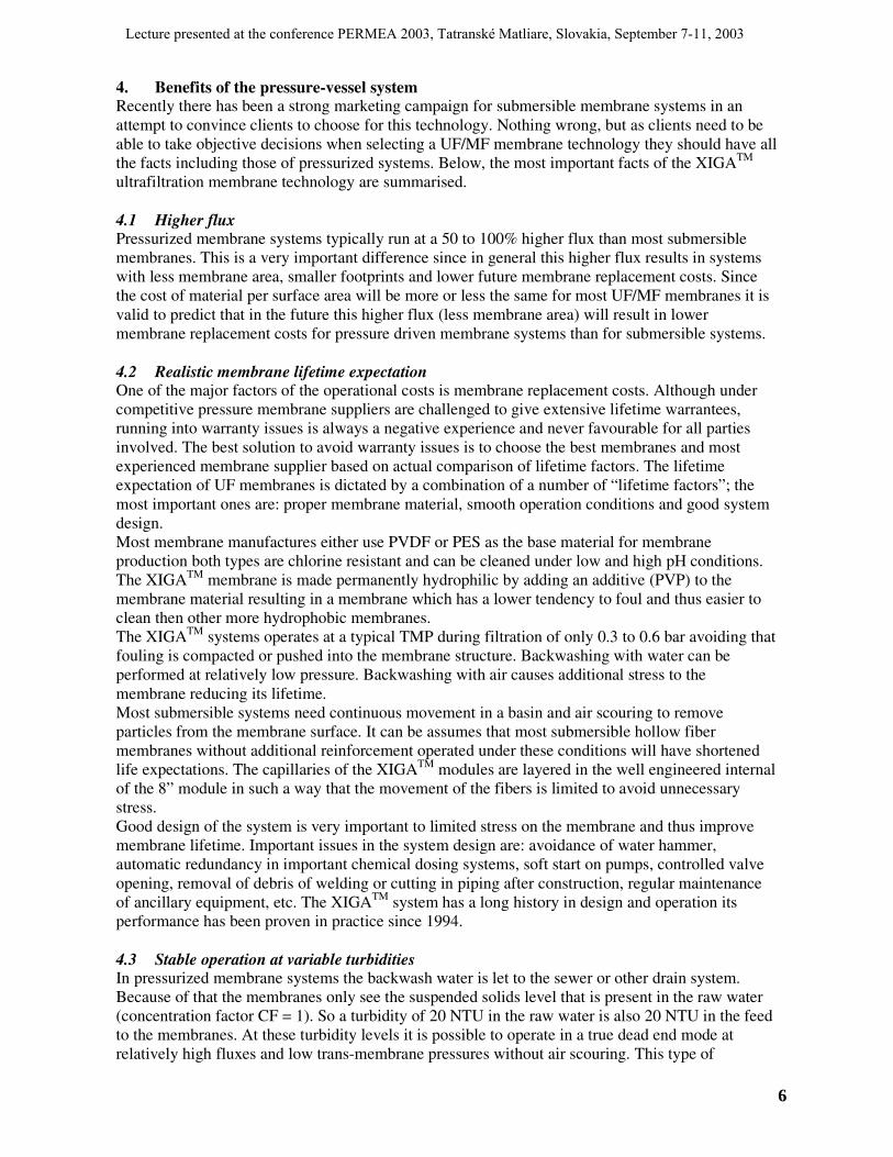
4. Benefits of the pressure-vessel system Recently there has been a strong marketing campaign for submersible membrane systems in an attempt to convince clients to choose for this technology. Nothing wrong, but as clients need to be able to take objective decisions when selecting a UF/MF membrane technology they should have all the facts including those of pressurized systems. Below, the most important facts of the XIGATM ultrafiltration membrane technology are summarised. 4.1 Higher flux Pressurized membrane systems typically run at a 50 to 100% higher flux than most submersible membranes. This is a very important difference since in general this higher flux results in systems with less membrane area, smaller footprints and lower future membrane replacement costs. Since the cost of material per surface area will be more or less the same for most UF/MF membranes it is valid to predict that in the future this higher flux (less membrane area) will result in lower membrane replacement costs for pressure driven membrane systems than for submersible systems. 4.2 Realistic membrane lifetime expectation One of the major factors of the operational costs is membrane replacement costs. Although under competitive pressure membrane suppliers are challenged to give extensive lifetime warrantees, running into warranty issues is always a negative experience and never favourable for all parties involved. The best solution to avoid warranty issues is to choose the best membranes and most experienced membrane supplier based on actual comparison of lifetime factors. The lifetime expectation of UF membranes is dictated by a combination of a number of “ lifetime factors” ; the most important ones are: proper membrane material, smooth operation conditions and good system design. Most membrane manufactures either use PVDF or PES as the base material for membrane production both types are chlorine resistant and can be cleaned under low and high pH conditions. The XIGATM membrane is made permanently hydrophilic by adding an additive (PVP) to the membrane material resulting in a membrane which has a lower tendency to foul and thus easier to clean then other more hydrophobic membranes. The XIGATM systems operates at a typical TMP during filtration of only 0.3 to 0.6 bar avoiding that fouling is compacted or pushed into the membrane structure. Backwashing with water can be performed at relatively low pressure. Backwashing with air causes additional stress to the membrane reducing its lifetime. Most submersible systems need continuous movement in a basin and air scouring to remove particles from the membrane surface. It can be assumes that most submersible hollow fiber membranes without additional reinforcement operated under these conditions will have shortened life expectations. The capillaries of the XIGATM modules are layered in the well engineered internal of the 8” module in such a way that the movement of the fibers is limited to avoid unnecessary stress. Good design of the system is very important to limited stress on the membrane and thus improve membrane lifetime. Important issues in the system design are: avoidance of water hammer, automatic redundancy in important chemical dosing systems, soft start on pumps, controlled valve opening, removal of debris of welding or cutting in piping after construction, regular maintenance of ancillary equipment, etc. The XIGATM system has a long history in design and operation its performance has been proven in practice since 1994. 4.3 Stable operation at variable turbidities In pressurized membrane systems the backwash water is let to the sewer or other drain system. Because of that the membranes only see the suspended solids level that is present in the raw water (concentration factor CF = 1). So a turbidity of 20 NTU in the raw water is also 20 NTU in the feed to the membranes. At these turbidity levels it is possible to operate in a true dead end mode at relatively high fluxes and low trans-membrane pressures without air scouring. This type of
Lecture presented at the conference PERMEA 2003, Tatranské Matliare, Slovakia, September 7-11, 2003
6

operation is typical very stable. A rapid increase of the turbidity or suspended solids level in the raw water in general only affects the trans-membrane pressure which will rise between two backwashes but will not lead to unstable operation and shut downs of the system. Therefore, the XIGATM system can operate stable at variable relatively high turbidities. In contradiction to a pressurized system the backwash water of most submersible system is recycled in the feed tank which happens also to be the membrane holding tank. The concentration of suspended solid in that tank can be much higher than the concentration in the raw water (CF>1). With a turbidity of 20 NTU, for instance, in the raw water the feed water surrounding the membranes can have a turbidity level up to 400 NTU in some submersible systems. At these increased turbidity and suspended solids levels, air scouring in combination with a relatively low flux is necessary to create membrane movement and a type of circulation of suspended solids in the tank along the membrane surface to avoid rapid cake build up. Most submerged membrane systems typically can operate at high turbidities but if the balance between flux, trans-membrane pressure and air scouring is disturbed by, for example, a rapid increase in suspended solids and or turbidity in the raw water, the membranes could easily block resulting in unstable operation and in some cases system shutdowns. To avoid this, it is noticed that many submersible systems are operated at uneconomical settings for flux, air, CIP’s resulting in plant performance below expectations. 4.4 CEB instead of CIP procedures The XIGATM system is equipped with a fully automated CEB to clean their membranes. To clean submersible membranes, especially in smaller systems, some submersible membranes have to be manually removed from their tanks by the operators with the help of cranes and be put into a separate CIP tank where chemicals will be added. In other cases the CIP is done in the membrane holding tank and an expensive automated CIP system to circulate chemicals through the membrane should be installed. Special care has to be taken to the chemical resistance of the construction materials and/or coating of the membrane holding tanks. In additions the CIP chemicals in open tanks could also create additional corrosion and unsafe working conditions. 4.5 Accurate integrity testing In many XIGATM membrane systems the integrity of the membranes is tested on a daily basis by means of a fully automated pressure decay or airflow test. Advantage of the airflow test is that it can be done very quickly and very accurate. The feed site of the membrane rack will be drained and a low static air pressure of 1 bar is applied on the feed site of the membrane. On the permeate side of the membrane rack a flow meter is installed. If there are no membrane failures in the rack the flow meter only measures the so-called diffusive air going through the membrane wall pushing the water on the permeate side out of the membrane through the flow meter. In case of a broken fiber the air passes through easily pushing an increased volume of water out of the membrane causing the flow meter to register an increase in flow. Determination of the location of the single broken fiber can either be done by sonic testing or isolation of the individual pressure vessels by valves installed in the pressure vessel permeate tubes. Integrity testing in a submersed system is usually done by means of the pressure decay test. Once the rack is located, finding a broken fiber in a packed submersed membrane system can be a very difficult exercise. If there is some contaminant like foam on the water surface it will be extremely difficult to locate the bubbles indicating a broken fiber. In contradiction to pressurized systems in most submersible systems test pressure is applied to the permeate side of the membrane having some additional disadvantages, such as: • Risks of contamination of the permeate side of the membrane by micro organisms in the
compressed air or oil.
Lecture presented at the conference PERMEA 2003, Tatranské Matliare, Slovakia, September 7-11, 2003
7

• Practice has proven that because pressure is put in opposite direction as production flow, small holes can be closed during testing so membranes could seem to be intact but are not in reality.
4.6 Lower risk for bacteria breakthrough in case of fiber failure As mentioned before the backwash water of most submersible systems (including bacteria and viruses) is recycled to the feed tank which is also the membrane holding tank. This means that the concentration factor of bacteria and viruses in the tank surrounding the membranes is higher (up to 20 times for some systems) than in a pressurized system where after every backwash the backwash water is let to the sewer or separate backwash water holding tank (CF=1). With this in mind it is obvious that the risks of a breakthrough in case of a fiber break in a submerged membrane is much higher than with a pressurized membrane.
Figure 7: 4 Standard UF stacks. 4.7 Easy to construct RO look- a-like UF membrane skids The XIGATM UF technology is based on RO pressure vessel configurations (Figure 7). The pressure vessel based configuration has many advantages over submersible systems such as: • No dedicated unique parts. All components to assemble and maintain a UF skid are state of the
art and globally available without any restrictions and or limitations by any patents, etc.; • In general every OEM that has experience designing and building RO systems is able to design
and build a UF system; • The pressure vessel design provides very easy access to the membranes. All membranes can be
accessed from the front or the back of the skid. No cranes are needed on top to move membrane modules;
• Pressure vessels are worldwide standard available for UF for competitive prices. 4.8 Small footprint The number of membrane modules in a single pressurized skid can be as high as 160 resulting in a total membrane area of 5600 m2 per skid. Based on an average flux of 85 l/(m2h) resulting in an output of one skid as high as 476 m3/hr. The footprint of a single skid containing 160 modules (40
Lecture presented at the conference PERMEA 2003, Tatranské Matliare, Slovakia, September 7-11, 2003
8

pressure vessels) is only 7 x 3 m = 21 m2. Other positive effects of the low number of skids are, of course, less valves, less PLC I/O’s, simple software, smaller electrical cabinets, etc. 4.9 Closed treatment system Because of the open tanks in combination with air scouring as used in most submersible systems, the humidity level will increase in the vicinity of the tanks and in general in the membrane building. This increased humidity could cause excessive condensation on the piping and instrumentation. If the feed or water contains free chlorine this condensation could result in an increased corrosion level and thus a shortened overall lifetime of the plant. Pressurized membrane systems are closed systems so the humidity in the membrane building is equal to outside conditions. Therefore there is no accelerated corrosion of piping and instruments or possibility of aerosolized pathogens which under certain circumstances could cause a risk for people’s health. The problems will increase in closed areas with poor ventilation, in these cases special care has to be taken with respect to the overall plant design, ventilation, and operating and maintenance procedures.
Figure 8: 6,700 m3h-1 ultrafiltration water plant. 4.10 Replacement membranes available from multiple suppliers Membranes are consumables and for most customers’ consumables are a serious part of the company’s yearly budget costs. For that reasons most companies are looking to use standardized products so they can benefit from (future) market pricing. This has, for example, happened in the RO industry with the standardized 8 inch modules, where prices have dropped significantly due to increased volumes and market pressure. At this moment most membrane modules, cassettes, configurations and even in some cases the operation of the submersible systems are unique and protected by patents. Customers cannot replace one brand with another binding them exclusively to one supplier for the rest of the systems lifetime, leaving clients exposed to the “ exclusive” suppliers pricing and portfolio policies. Not only clients cannot benefit from future market pricing, clients also run the risk that the membrane supplier stops producing the replacement module making the investment of the client worthless. Since the start of the production in 1994, the 8 inch UF element was standardized such as the 8” x 60” RO look-a-like modules, which is not protected by patents except for the hollow fibers and the internals. Nowadays, the 8 inch UF module is already being offered to the market by multiple suppliers.
Lecture presented at the conference PERMEA 2003, Tatranské Matliare, Slovakia, September 7-11, 2003
9

5. Applications Although UF is already applied in hundreds of different applications, large-scale plants in water treatment (Figure 8) are limited to a few of those: final pathogen barrier in potable water production; surface water treatment; sea water pre-treatment; and re-use of effluent. 5.1 Bacteria and virus free drinking water production Due to the increasingly stringent potable water quality regulations, water companies are putting more and more effort into avoiding microbial infections of their distribution networks. In doing so, they have to either abide by costly and frequent water quality analyses and periodical cleaning and flushing cycles or install a physical barrier for bacteria and viruses at the end of their water treatment works. Installing such a barrier is quite easy using UF. Another advantage is that less organic material enters the distribution network reducing post-growth of micro-organisms in the network. With UF membranes a 6 log removal of bacteria and a 4 log removal of viruses are achievable, dramatically increasing the consumer’ s and water company’ s peace of mind. An example of such an installation has a capacity of 6,700 m3/h and runs successfully for almost 2 years now and an 11,000 m3/h or 264,000 m3/day plant is under construction.
5.2 Surface water treatment The development of low-pressure high-flux RO membranes has renewed the interest in the possibilities of this membrane filtration process for water production applying other sources than sea water. Spiral wound RO membrane elements, however, are susceptible to fouling caused by particles present in the surface water or formed during the pre-treatment steps. The presently available high-flux low-fouling UF membranes of NORIT can overcome this problem by removing all the particles from the feed to the RO-system protecting the spiral wound membrane elements from plugging and fouling and extending their lifetime significantly. Typical installations cover a wide range from 25 to several thousands m3/h.
Lecture presented at the conference PERMEA 2003, Tatranské Matliare, Slovakia, September 7-11, 2003
10

5.3 Industrial wastewater effluent recycling Since the costs of potable water intake and effluent discharge have increased dramatically, recycling of effluent from wastewater treatment plants becomes very attractive. NORIT UF technology has proven to be the technically feasible and economically viable solution for capacities already ranging from 50 to 1,000 m3/h.
5.4 Municipal wastewater effluent recycling Stringent regulations for effluent discharge have led to ‘high’ quality effluent streams from municipal wastewater treatment plants. Instead of discharging this effluent to open waters, NORIT UF technology converts these effluents into an attractive alternative water source for irrigation water, drinking water, process water and cooling water. Current capacities installed are up to 1,000 m3/h. Under construction is the largest plant in the world with a capacity of 15,600 m3/h or 375,000 m3/day.
5.5 Seawater RO pre-treatment Replacing conventional pre-treatment processes, such as flocculation, sedimentation and multi media filtration by UF provides a high quality feed water to NF and RO. Fouling problems on the spiral wound RO elements, still common on most seawater RO plants in spite of extensive conventional pre-treatment, are solved, since the membrane pre-treatment step provides a constant quality feed water with very low SDI to the RO, so that RO membrane lifetime and overall efficiency are improved significantly. NORIT UF technology has proven to be the technically feasible and economically viable solution for capacities already ranging from 50 to several thousands m3/h.
Lecture presented at the conference PERMEA 2003, Tatranské Matliare, Slovakia, September 7-11, 2003
11
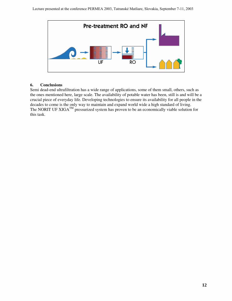
6. Conclusions Semi dead-end ultrafiltration has a wide range of applications, some of them small, others, such as the ones mentioned here, large scale. The availability of potable water has been, still is and will be a crucial piece of everyday life. Developing technologies to ensure its availability for all people in the decades to come is the only way to maintain and expand world wide a high standard of living. The NORIT UF XIGATM pressurized system has proven to be an economically viable solution for this task.
Lecture presented at the conference PERMEA 2003, Tatranské Matliare, Slovakia, September 7-11, 2003
12