Embed Size (px)
Citation preview

Not for Reproduction
Read and understand this instruction manual thoroughly before using the product. It contains important information for your safety as well as operating and maintenance advice.
BRIGGS & STRATTON IS A TRADEMARK OF BRIGGS & STRATTON CORPORATION AND IS USED UNDER LICENSE TO ALTON INDUSTRY LTD. GROUP
ULTRA-QUIET4 GALLON PORTABLE AIR COMPRESSOR
Product Model # 074060-00Manual # 80019549
BRIGGS & STRATTON CORPORATIONMILWAUKEE, WISCONSIN, U.S.A.

Not for Reproduction
BRIGGSandSTRATTON.COM
Thank you for purchasing this quality-built Briggs & Stratton ™ air compressor. We are pleased that Briggs & Stratton brand. When operated and maintained
according to the instructions in this manual, your Briggs &Stratton air compressor will provide many years of dependable service.
You can contact Briggs & Stratton Customer Service by phone at (800) 743-4115, or on the Internet at BRIGGSandSTRATTON.COM.
Date Purchased
2

Not for Reproduction
Thank you for choosing a product from the Briggs & Stratton family of brands. We are honored that you chose us as your power equipment provider.
WE STRIVE TO CREATE HELPFUL, DEPENDABLE PRODUCTS THAT YOU CAN RELY ON FOR YEARS TO COME, WHILE COUNTING ON US TO SUPPORT YOU THROUGH THE LIFE OF YOUR PRODUCT.
onlineproductregistration.com or scan the code below from your mobile device.
•
•
• Product updates
• Helpful maintenance and usage tips
• Discounts and offers on future products
product online.
Whether you absolutely love your new product or have a suggestion to enhance it, we’d love to hear from you and value your feedback.
At your service,
David Cluka, Director of Customer ExperienceBriggs & Stratton Corporation
CONGRATULATIONS ON YOUR NEW PRODUCT PURCHASE!
SCAN THIS CODE to start the registration process on your mobile device. Data rates apply.
David Cluka, Director of Customer Experience
80019549

Not for Reproduction
Table of Contents
Safety Guidelines..................................................................................................................
Product Registration Form....................................................................................................
Important Information...........................................................................................................
Assembly Instructions..........................................................................................................
Operating Instructions..........................................................................................................
Technical Specifications........................................................................................................
Maintenance.........................................................................................................................
Troubleshooting....................................................................................................................
Exploded View.......................................................................................................................
Parts List...............................................................................................................................
Warranty...............................................................................................................................
Key Parts diagram.................................................................................................................
BRIGGSandSTRATTON.COM4
SAVE THESE INSTRUCTIONSThis manual contains important safety and operating instructions. Read all instructions and follow them with use of this product.
3
5
8
9
11
12
14
15
17
18
19
20

Not for ReproductionFlying Objects
Operator's Manual
Hot Surface
Electrical ShockToxic Fumes
Safety Guidelines
Important Safety Information
Safety Symbols and Meanings
The manufacturer cannot possibly anticipate every possible circumstance that might involve a hazard. The warnings
work method, or operating technique that the manufacturer does not specifically recommend, you must satisfy yourself that it is safe for you and others. You must also make sure that the procedure, work method, or operating technique that you choose does not render the compressor unsafe.
Warning
BurstingFire
The safety alert symbol indicates a potential hazard to personal injury. A signal word (DANGER, WARNING, or CAUTION) is used with the alert symbol to designate a degree or level of hazard seriousness. A safety symbol may be used to represent the type of hazard. The signal word NOTICE is used to address practices not related to personal injury.
indicates a hazard which, if not avoided, will result in death or serious injury.
indicates a hazard which, if not avoided, could result in death or serious injury.
indicates a hazard which, if not avoided, could result in minor or moderate injury.
address practices not related to personal injury.
DANGER
WARNING
CAUTION
Notice
5

Not for Reproduction
DO NOT OPERATE THIS UNIT UNTIL YOU READ AND UNDERSTAND THIS INSTRUCTION MANUAL FOR SAFETY, OPERATION, AND MAINTENANCE INSTRUCTIONS.
compressor.
.Do not restrict compressor ventilation openings or place objects against or on top of compressor. Operate compressor only in a clean, dry, well ventilated area.
High pressure air could result in death or serious injury. Never operate above maximum operating pressure of the spray gun or tool. Drain water from tank after each use. Do not weld or repair tank.
or ignition sources including the compressor unit.
High pressure air could result in death or serious injury. Do not operate with pressure switch or safety valve set above maximum allowable working pressure.
Hot compressors surfaces could result in serious injury. Allow compressor to cool before touching.
Inhalation hazard. Using compressor to supply breathing air could result in death or serious injury. Do not use compressor to supply breathing air.
Risk of serious eye injury. Always wear ANSI Z87.1 approved safety goggles when using air compressor. Do not spray any part of the body.
Safety Information
6
WARNING
.Do not operate unattended. Always turn off and unplug unit when not in use.
Shock risk could result in death or serious injury. Only connect compressor to a properly grounded receptacle. KEEP CHILDREN AWAY FROM THE AIR COMPRESSOR AT ALL TIMES.
BRIGGSandSTRATTON.COM

Not for Reproduction
As the distance from the supply outlet increases, you must use a heavier gauge extension cord. Useing extension cords with inadequately sized wire causes a serious drop in voltage, resulting in loss of power and possible product damage. Refer to the table here to determine the required minimum wire size.
Extension Cords
The smaller the gauge number of the wire, the greater the capacity of the cord. For example, a 14 gauge cord can carry a higher current than a 16 gauge cord. When using more than one extension cord to make up the total length, be sure each cord contains at least the minimum wire size required.
Guidelines for using extension cords
-A"("W" in Canada) to indicate it is acceptable outdoor use.
• Ensure your extension cord is properly wired and in good electrical condition. Alway replace a
• Protect your extension cords from sharp objects, excess heat, and damp or wet areas.
Recommended Minimum Wire Gauge for Extension Cords* (120 V)
0 - 55.1 - 8
8.1 - 1212.1 - 1515.1 - 20
1616141210
1616141210
1616141210
14121010-
1210---
12----
CORD SIZE IN AWG (AMERICAN WIRE GAUGE)Extension cord length in feet
*
AMPERERATING
25' 50' 75' 100' 150' 200'
Dust can be created when cutting, sanding, drilling or grinding materials such as wood, paint, metal, concrete, cement, or other masonry. To reduce your exposure to these chemicals, work in a well ventilatedarea and ALWAYS wear approved safety equipment.
This product contains chemicals, including lead, know to the state of California to cause cancer and birth defects or other reproductive harm. Wash hands after handling.
7

Not for Reproduction
BRIGGSandSTRATTON.COM8
This BRIGGS&STRATTON Air Compressor is ideal for a wide range of applications from fastening to greasing and engine cleaning. The 4 U.S.gallon (15.1L) design provides optimum pressure. It features a 3/4 HP induction motor for quiet operation and a cast-iron, oil-less pump for long-lasting, reliable performance.
The procedures described in this manual are solely for this 4 U.S.gallon (15.1L) air compressor at a maximum of P=125 PSI. The device has been designed and constructed for household use only.
Important Information
Always ensure the use of appropriately matched air tools with your BRIGGS&STRATTON ™Air Compressor. Be sure that the air compressor being used can supply the appropriate volume, pressure and delivery rate of air to the tool(s) without running continuously. Using tools or combinations of tools that, together or separately, require more than the air compressor can deliver will void the air compressor guarantee/warranty.
Compatible compressor and air tool - proper usage and operation
Tool Compatibility Chart
Air Tool Operates ToolContinuously
Operates ToolIntermittently
Inflation/Cleaning
Finishing Nailer(16 gauge)
Framing Nailer
Flooring Nailer
Brad nailer(18 gauge)
Roofing Nailer
Horizontal / Vertical Use Option
1. This unit can be used vertically if needed. It is recommended to use the unit in a horizontal position.

Not for Reproduction
9
Key Parts Diagram
E. Air Pressure Regulator
G. Outlet Pressure Gauge
F. Tank Pressure Gauge
D. Safety Valve
H. Air OutletB. Air Compressor Pump
A. Electric Motor
K. Power Cord
J. Air Tank
I. Air Tank Drain ValveC. Pressure Switch
A
B
H
G
DC
F
I J K
E
Not for Reproduction
BRIGGSandSTRATTON.COM10
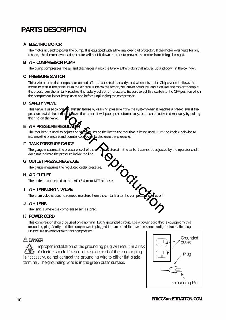
PARTS DESCRIPTION
The motor is used to power the pump. It is equipped with a thermal overload protector. If the motor overheats for any reason, the thermal overload protector will shut it down in order to prevent the motor from being damaged.
ELECTRIC MOTORA
The pump compresses the air and discharges it into the tank via the piston that moves up and down in the cylinder. AIR COMPRESSOR PUMPB
C
D
E
F
G
H
The regulator is used to adjust the pressure inside the line to the tool that is being used. Turn the knob clockwise to increase the pressure and counter-clockwise to decrease the pressure.
AIR PRESSURE REGULATOR
I
K
The gauge measures the pressure level of the air that is stored in the tank. It cannot be adjusted by the operator and it does not indicate the pressure inside the line.
TANK PRESSURE GAUGE
J
This valve is used to prevent system failure by draining pressure from the system when it reaches a preset level if the pressure switch has not shut down the motor. It will pop open automatically, or it can be activated manually by pulling the ring on the valve.
SAFETY VALVE
This switch turns the compressor on and off. It is operated manually, and when it is in the ON position it allows the motor to start if the pressure in the air tank is below the factory set cut-in pressure, and it causes the motor to stop if the pressure in the air tank reaches the factory set cut-off pressure. Be sure to set this switch to the OFF position when the compressor is not being used and before unplugging the compressor.
PRESSURE SWITCH
The outlet is connected to the 1/4” (6.4 mm) NPT air hose. AIR OUTLET
The gauge measures the regulated outlet pressure.
OUTLET PRESSURE GAUGE
The drain valve is used to remove moisture from the air tank after the compressor is shut off.
AIR TANK DRAIN VALVE
The tank is where the compressed air is stored.AIR TANK
This compressor should be used on a nominal 120 V grounded circuit. Use a power cord that is equipped with a
Do not use an adaptor with this compressor.
POWER CORD
DANGERImproper installation of the grounding plug will result in a risk of electric shock. If repair or replacement of the cord or plug
is blade terminal. The grounding wire is in the green outer surface.
Grounded outlet
Grounding Pin
Plug

Not for Reproduction
11
Assembly Instructions
The carton should contain:
• Unpack the air compressor unit. Inspect the unit for damaged. If the unit has been damaged, contact the retailer immediately.
it has the required pressure rating for its intended use.
Positioning of the air compressor1. Position the air compressor (1) near an electrical outlet (2)( ).
2. The compressor must be at least 12”(31cm) from any wall (3) or obstruction, in a clean, well-ventilated area to ensure
).
The air compressor must be level to ensure proper drainage of the moisture in the tank.
Connect air hose to compressor
1. Connect the air hose (1) to the compressor’s air outlet (2) with the quick conncetor (3)( ).
Note: Air hose and quick connector are not provided, need to be purchased separately. Apply plumber's tape on all the threads to prevent air leakage.
12
3
Fig A
Notice
Hot compressor surfaces could result in serious injury. Allow compressor to cool before touching.
High pressure air could result in death or serious injury. Never operate above maximum operating pressure of the spray gun or tool.
If the pump has been transported or turned upside down (even partially), allow the pump to sit in a normal, upright position for approximately 10 minutes before starting.
WARNING
WARNING
• Air compressor• Owner's manual
High pressure air could result in death or serious injury. Shut off unit, unplug and release air pressure prior to servicing.
High pressure air containing water condensation could result in minor or moderate injury. Do not spray at any person.
CAUTION
WARNING
WARNING
Risk of serious eye injury from moisture and debris. Always wear ANSI Z87.1 safety goggles when opening drain valve.
12 / 31 cm
Fig B 1
2
3

Not for Reproduction
BRIGGSandSTRATTON.COM12
).
1
Fig E
4. Plug in the power cord.
• Use a dedicated circuit. The compressor will use the full capacity of a typical 15A household circuit. If any other electrical devices are drawing from the compressor's circuit, the air compressor may fail to start. Low voltage or an overload circuit can result in sluggish starting that causes the motor overload protection system or circuit breaker to trip, especially in cold conditions.
• Disconnect the power cord only after break-in process has been completed, otherwise the motor might get damaged.
5. Set the pressure switch (1) to the ON position. The compressor will start. Run the compressor for 30 minutes. If it fails, turn it off immediately and call the toll-free helpline at: 1-800-743-4115.
use( ).
6. After 30 minutes, turn off the pressure switch.
7. Close the tank drain valve (1) by turning it clockwise ( ).
pressure and then the compressor's motor will stop. The compressor is now 8. Set the pressure switch to the ON position. The air receiver will fill ti cut-out
ready for use.
2. Open tank drain valve (1) by turning it counter-clockwise to permit the air to escape and prevent air pressure build-up in the air tank during the break-in period (
3. Turn the air pressure regulator knob (1) clockwise until it stops ( ).
Break in the pump1.Set the pressure switch (1) to the OFF position ( ).
Operating Instructions
Fig F
1
Fig C
Fig G
Fig D
1
1
OFF
ON
1
OFF
ON

Not for Reproduction
2
1
13
Operating Instructions
3. Attach hose and accessories ( ).(Hose and accessories need to be purchased separately.)
3. Set the pressure switch to the ON position and allow the tank pressure to build. Motor will stop when tank pressure reaches cut-out pressure.4. Turn the air pressure regulator knob clockwise until desired pressure is reached.5. The compressor is ready for use.
1. Close the tank drain valve (12. Plug-in the power cord(2)( )
( )
How to start
Fig K
How to shut down
1.Set the pressure switch (1) to the OFF position.2.Unplug the power cord ( 2).
.
3.Reduce the pressure in the tank through the outlet hose. Pulling the safety valve ring ( 3) and keeping it open will also reduce the pressure in the tank (
the ).
2
3
1
Fig L
Fig I
1. Set the pressure switch (
2. Turn the air pressure regulator knob (1) counter-clockwise until it stops
Before each start-up1) to the OFF position ( ).
( ).
Fig H
Fig J
1
1
OFF
ON

Not for Reproduction
BRIGGSandSTRATTON.COM14
Check Safety ValveBefore starting the compressor, pull the ring on the safety valve to make sure that the safety valve operates freely. If the valve isstuck or does not operate smoothly, contact a trained servicetechnician.
How To Drain Tank1. Set the pressure switch to the O (OFF) position.2. Unplug the power cord.3. Turn air pressure regulator knob counter-clockwise to set the outlet pressure to zero.4. Pull and hold ring on safety valve, allowing air to bleed from the tank until air pressure is minimized.5. Place suitable container under unit to catch water. 6. Slightly tilt unit and turn drain valve counter-clockwise to open.7. After the water has been drained,close the drain valve(clockwise). The air compressor can now be stored.
How to Clean The Air Filter
Check that all connections are tight. Small leaks in the tank, hoses,connections or transfer tubes will substantially reduce the air compressor and tool performance. Spray a small amount of soapy water around the area of suspected leaks with a spray bottle. If bubbles appear, repair, replace or reseal the faulty component. Do not over-tighten any connections.
Before storing the air compressor:• Drain tank (page 14).• Use an air blow gun to clean all dust and debris from the compressor.• Disconnect and wind up the power cord.• Clean the ventilation openings on the motor enclosure with a damp cloth.• Drain all moisture from the tank.• Pull the pressure safety valve to release all pressure from the tank.• Cover the entire unit to protect it from moisture and dust.• Store the air compressor in a clean and dry location.• In cold weather, store the compressor in a warm building when it is not in use. This will reduce problems related to starting the motor and the freezing of water condensation.
Pull the safety valve daily to ensure that it is operating properlyand to clear the valve of any possible obstructions.
DESCRIPTION / REASONSERVICEINTERVAL ITEM
Through normal operation of your air compressor, conndensation of water will accumulate in the tank. To prevent corrosion of the tank from the inside, condensation must be drained at the end of every workday. Be sure to wear protective goggles. Relieve the air pressure in the system then open the drain valve on the bottom of the tank to drain. Under cold conditions it is especially important to drain the tank after each use to reduce the chance of problems resulting from the freezing of condensation water. NOTE: Refer to instructions on how to drain tank (page 14).
Drain the tank
Check the valve
Test for leaks
Storage
Daily
Daily
Monthly
Prior to storing
Maintenance
a regular basis. Clean the cartridge filter by blowing on it with a blow gun (page 14).
Weekly
A dirty filter will reduce the unit s performance and life. To avoid any contamination inside the pump, the filter should be cleaned weekly and replaced on a regular basis. The cartridge filter should be cleaned with blow gun.
I

Not for Reproduction
15
Troubleshooting
The power cord is not plugged in.
The motor’s thermal overload protection has tripped.
POSSIBLE CAUSEPROBLEM
The motor will not run or start
Plug the power cord into a grounded outlet.
Set the power switch to the ON position.The power switch is in the O (OFF)position.
The extension cord is the wrong wire gauge or is too long.
A fuse has blown or a circuit breaker has been tripped.
The air tank pressure exceeds the preset pressure switch limit.
The safety valve is stuck open.
Electrical connections are lose.
The motor, capacitor or safety valve is defective.
The motor runscontinuously when the pressure switchis in the ONposition.
Check extension cord information (page 7) for the proper wire gauge and cord length.Turn the air compressor off, unplug the power cord and wait until the motor has cooled down. Plug in the power cord only after the motor has cooled down, and wait wait at least 5 minutes to make sure the thermal overload protector has recovered.
Replace the fuse or reset the circuit breaker.
Verify that the fuse has the proper amperage.
Check for low voltage conditions.
Disconnect any other electrical appliances from the circuit or operate the compressor on a dedicated circuit.
The motor will start automatically when the tank pressure drops below the cut-in pressure.
Clean or replace the safety valve.
Contact an authorized service center, or call 1-800-743-4115Contact an authorized service center, or call 1-800-743-4115
Set the pressure switch to the OFF position. If the motor does not shut off, unplug the air compressor. If the pressure switch is defective, replace it.
Check the air requirements of the accessory that is being used. If it is higher than the CFM (Cubic Feet per Minute) and pressure supplied by the compressor (page 18), a larger capacity air compressor is needed.Most accessories are rated at 25% of actual CFM while
running continuously.
The pressure switch does not shut off the motor when the air compressor reaches the cut-out pressure and the safety valve activates.
The compressor’s capacity is not enough.
The regulator doesnot regulate thepressure.
The regulator or its internal parts are dirtyor damaged.
Replace the regulator.
SOLUTIONS

Not for Reproduction
BRIGGSandSTRATTON.COM16
Prolonged excessive use of air.
POSSIBLE CAUSEPROBLEM
The pressure is low or there is not enough air.
Close the drain valve.
Check the fittings with soapy water. Tighten or resealleaking fittings (apply plumber s tape on threads). Do not over tighten.
Clean or replace the air filter element.
SOLUTIONS
The tank drain valve is open.
There is a leak at one of the fittings.
The air intake is restricted.
There is a hole in the air hose.
There is condensation in the air tank caused by a high level of atmospheric humidity or because the air compressor has not been running long enough.
The tank leaks.
The ventilation is inadequate.
Cooling surfaces are dirty.
There is moisture in the discharge air.
Decrease the amount of air used.
Check the air hose and replace it if necessary.
Replace the tank immediately. Do not attempt to repair it.
Relocate the compressor to an area with cool, dry andwell-circulated air.
Clean all cooling surfaces on the pump and the motorthoroughly.
Replace worn parts and reassemble using newplumber's tape.
The compressoroverheats.
Check for worn parts and replace them if necessary.
Drain the air tank after each use. Drain the air tank moreoften in humid weather and use an air-line filter.
The valve is leaking.
The valve is leaking.

Not for Reproduction
17
Briggs & Stratton Air Compressor Warranty Policy
This Limited warranty does not include the following:
LIMITED WARRANTY
A. Parts that are worn or broken or which have become inoperative due to abuse, misuse, accidental damage, neglect or lack of proper installation, operation or maintenance (as outlined in the applicable owner’s manual or operating instructions) or product that has been used for industrial, professional, commercial or rental purposes;B. Normal wear and tear or expendable parts or accessories that may be supplied with the product which are expected to become inoperative or unusable after a reasonable period of use;C. Routine maintenance and consumable items such as, but not limited to fuel, lubricants, valves, belts, knobs, nuts, fluids, tune-ups, or adjustments; D. Damage caused by repairs made or attempted by persons not authorized by the manufacturer;E. Product that was sold to the original purchaser as reconditioned or refurbished product (unless otherwise specified in writing); F. Product or parts thereof if any part from another manufacturer has been installed or any repairs or alterations have been made or attempted by unauthorized persons;G. Normal deterioration of the exterior finish such as, but not limited to, scratches, dents, paint chips, nor any corrosion or discoloring by heat, abrasive and chemical cleaners;H. Component parts sold by and identified as the product of another company, which shall be covered under the other product manufacturer’s warranty, if any.
October, 2015
These are our standard warranty terms, but occasionally there may be additional warranty coverage that was not determined at time of publication. For a listing of current warranty terms for your air compressor, go to BRIGGSandSTRATTON.COM
BRIGGS & STRATTON is a trademark of BRIGGS & STRATTON CORPORATION and is used under license to Alton IndustryCo. Ltd®. Alton Industry Co. Ltd warrants this Briggs & Stratton brand product for a period of one year from the date of original retail purchase against defects in materials and workmanship. Subject to the conditions and limitations described below, if Alton Industry Co. Ltd determines this product is covered under this warranty, it will be replaced with the samemodel or one of equal value or specification, at Alton Industry Co. Ltd’s option. Alton Industry Co. Ltd will bear the cost of replacement. The purchaser must contact Alton Industry Co. Ltd® for all warranty authorizations.
There is no other express warranty. Implied warranties, including those of merchantability and fitness for a particular purpose, are limited to one year, or to the extent permitted by law. Liability for incidental or consequential damages are excluded to the extent exclusion is permitted by law. Some states or countries do not allow limitations on how long an implied warrant lasts, and some states of countries do not allow the exclusion or limitation of incidental or consequential damages, so the above limitation and exclusion may not apply to you. This warranty gives you specific legal rights and youmay also have other rights which vary from state to state or country to country.
Save your proof of purchase receipt. If you do not provide proof of the initial purchase date at the time warranty service is requested, the manufacturing date of the product will be used to determine the warranty period. Product registration is not required to obtain warranty service on Briggs & Stratton products.
TM
TM
For questions about our warranty on this product, contact us at:Alton Industry LTD. Group1031 North Raddant Road
Batavia Illinois 60510888-899-0146

Not for Reproduction
BRIGGSandSTRATTON.COM18
*CFM: Cubic Feet per Minute.
This compressor is rated in accordance with ISO 1217, displacement compressors acceptance tests.
Model No.
Pump
Motor
Voltage/Amps/HZ
Cut-in Pressure
Air Tank Capacity
Cut-out Pressure
CFM @ 40 PSI
CFM @ 90 PSI
Power Cord
Oil free, Direct drive, Single stage
074060-00 / 3300441
1 HP
120/7.5/60
4 Gallon
95 PSI
125 PSI
3.3
2.4
SJT 18 AWG / 72 in. Length
**
NOTE: Avoid use of extension cords. If use of an extension cord cannot be avoided, the cord should be a minimum wire size of 14 AWG and no longer than 30 feet. Use only a 3-wire extension cord that has a 3-blade grounding plug and a 3-slot receptacle that will accept the plug on the product.

Not for Reproduction
19
Exploded View

Not for Reproduction
BRIGGSandSTRATTON.COM20
Parts List
Wire Fixing
Capacitor
Rubber Hoses
Pressure Switch
Check Valve
Power Cord
Washer Φ5
Rubber Pad I
Drain Valve
Self-tapping Screw M5x14
Bleeding Tube
Capacitor Holder
17
18
19
20
21
22
23
24
25
26
27
28
29
30
Handle Grip
Quick Coupler
Regulator
Plug
Regulator Knob
Elbow
Bolt M5x12
Control Panel
Pressure Gauge
Safety Valve
Air Filter
Pump/motor Assembly
Screw M4x10
Rubber Foot
Transfer Tube
Capacitor Cover
Connector
01
02
03
04
05
06
07
08
09
10
11
12
13
14
15
1
2
1
1
3
2
3
1
1
2
1
1
1
1
4
Nut M616 4
1
1
2
1
1
1
2
1
1
1
4
1
12
18Rubber pad II31 2Air tank32 1
Description Qty.No.Description Qty.No.