Embed Size (px)
Citation preview
Ultra-Prop ™
ASSEMBLY, INSTALLATION OPERATION & MAINTENANCE INSTRUCTIONS
Your Ultra-Prop has been designed and manufactured for easy assembly and long life. Although assembly may appear obvious, by following these instructions, you can be certain your prop will not only function correctly, but will give all the performance and durability expected.
VERY IMPORTANT NOTE: Illustrations depict a left-hand pusher propeller installation (counter clockwise rotation viewed from behind vehicle). For right-hand propeller installation (clockwise rotation viewed from behind vehicle). Install pitch blocks opposite to that shown in Figures 2, 3 and 4.
PRE-ASSEMBLY
Before beginning assembly of your Ultra-Prop, review the performance charts in the brochure or on line at competitionaircraft.com to be certain you have selected the correct propeller model and pitch block degree for your aircraft. Check the “Propeller Recommendations” list. 1. Begin by laying out all the parts on a clean table or floor. 2. Be sure you have the appropriate number of blades, hub halves, pitch blocks, bolt sleeves and hardware. (See Table 1 below and photo
on back of brochure.) _________________________________________________________________________________________________________________
TABLE 1 INDIVIDUAL ULTRA-PROP KIT
PRODUCT CONTENTS
ITEM 2-BL KIT 3-BL KIT 4-BL KIT A/N Bolts 4 6 8 A/N Washers 8 12 16 A/N Locknuts 4 6 8 Pitch Blocks 4 6 8 Prop Blades 2 3 4 Hub Halves 2-2bl 2-3bl 2-4bl
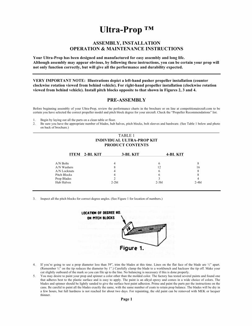
3. Inspect all the pitch blocks for correct degree angles. (See Figure 1 for location of numbers.)
4. If you’re going to use a prop diameter less than 59”, trim the blades at this time. Lines on the flat face of the blade are ½” apart.
(Remember ½” on the tip reduces the diameter by 1”.) Carefully clamp the blade to a workbench and hacksaw the tip off. Make your cut slightly outboard of the mark so you can file up to the line. No balancing is necessary if this is done properly.
5. You may desire to paint your prop and spinner a color other than the molded color. The factory has tested several paints and found one that adheres best to the plastic surface and is easy to apply. The paint is an alkyd epoxy and comes in a wide choice of colors. The blades and spinner should be lightly sanded to give the surface best paint adhesion. Prime and paint the parts per the instructions on the cans. Be careful to paint all the blades exactly the same, with the same number of coats to retain prop balance. The blades will be dry in a few hours, but full hardness is not reached for about two days. For repainting, the old paint can be removed with MEK or lacquer thinner.
Page 1

ASSEMBLY ___________________________________________________________________________
WARNING: The “early” snap-on spinner, without the bracket and spinner retention screw, should not be used on tractor
installations. If it comes off, blade damage could affect performance during a critical phase of flight. ___________________________________________________________________________
1. Begin the prop assembly by pushing all the blade bolts through the flat, outer face of one hub with one washer under each bolt head. 2. Lay this hub half flat on your work area with the bolt heads down. Then rotate it so that any one of the blade openings and pair of bolts
are facing toward you. (See Figure 2.) 3. Hold a pitch block in the position shown in Figure 2 and slip it down over the pair of bolts until it seats firmly in the blade opening of
the hub.
4. Now rotate the hub half of each remaining blade opening and repeat the correct positioning and seating of the pitch blocks. 5. Slip the prop blades over the bolt pairs so that the flat side of each blade is face up (See Figure 3), and slide the remaining pitch blocks
down over the bolts until each seats firmly against the blade under it. IMPORTANT: The orientation of all pitch blocks and blades must be exactly as shown in figures 2 and 3 for correct operation. 6. Press the other hub half over the bolts. Wiggle the blades up and down to align holes. At the most, only a slight rap with your palm
should be required to push the bolts through the hub half. 7. Finish the assembly with one washer under each nut as shown in Figure 3. 8. Use a ¼” or 3/8” socket drive (or 7/16” box wrenches) and tighten bolts evenly. Move around the bolt circle several times and draw up
lightly each time. 110 to 120 in. lbs. is the recommended final torque.
IMPORTANT: Torque value is in INCH POUNDS not foot pounds. Check your torque wrench to avoid overtorquing. We strongly recommend NOT using a Foot Pound wrench as these torque values in ft. lb. are at the lower end of the tool’s scale and under or overtorquing the bolts is possible. NOTE: You must retorque these bolts after ONE hour of running and check the torque after each TEN (10) hours of flying until no further tightening is required. 9. Add the decals and prop tip striping tape to suit your taste. (These are enclosed in the owner’s data packet.) They increase the visibility
of a spinning prop. Remove the paper backing from the tape and wrap tape around, overlapping the ends at the trailing edge. Then peel the transparent carrier film from the surface of the tape.
Page 2

INSTALLATION
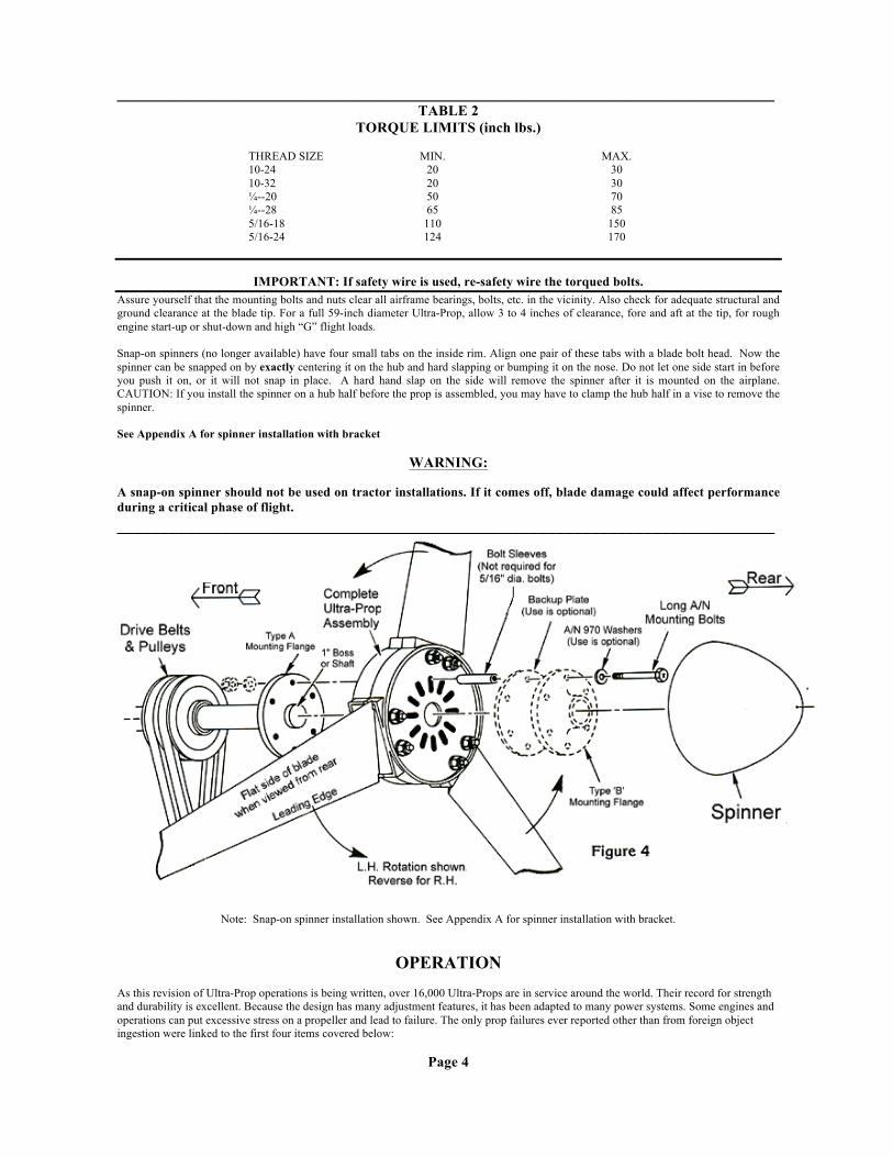
The correct operational position of the Ultra-Prop is with the flat side of the blades toward the rear of the plane. (See Figure 4) In this attitude, the leading edges of the blades are tilted forward in the hub. The Ultra-Prop hub has been designed to fit as many engines as possible. A one-inch diameter pilot hole is provided and your airplane’s shaft or the boss on your prop mounting flange must fit snuggly into this hole. (See Figure 4) For non-standard pilot holes, contact the factory for information concerning modification limits. Sanding, reaming or filing the hub is permissible but must be done carefully to keep the hole concentric or the prop balance could be affected. The twelve radial slotted holes in the hub will fit most flanges with 2-1/4” to 3-1/4” bolt circles. The slots are 5/16” or 8mm wide. For ¼” mounting bolts, bolt sleeves (available from the factory) must be used around the bolts. We strongly recommend that if your prop was attached with 3/16” bolts that you modify your mounting flange for ¼” hardware or larger for a structurally superior installation. Most wooden props use a backup plate when mounting the prop. This plate distributes mounting bolt loads and prevents crushing of the soft hub. The Ultra-Prop does not need this plate if heavy, large diameter A/N 970 type washers are substituted under the bolt heads. However, we recommend use of the crush plate if possible. Also, the Ultra-Prop hub is 2-1/4” thick and may require longer mounting bolts than those used on wood props. Check this bolt length carefully so thread engagement is adequate. Longer bolts can be obtained from a local hardware store or aircraft supply house. ___________________________________________________________________________
Caution: Use S.A.E. Class 8, or aircraft grade. Look for an ‘X’ on the bolt head. When tightening the nuts, follow the airplane manufacturer’s bolt torquing instructions. If they do not exist, the following table (Table 2) is a guideline for aircraft hardware with steel nuts or steel female threads.
IMPORTANT: torque value is in INCH POUNDS not foot pounds. Check your torque wrench to avoid overtorquing.
Page 3
__________________________________________________________________________________________ TABLE 2
TORQUE LIMITS (inch lbs.)
THREAD SIZE MIN. MAX. 10-24 20 30 10-32 20 30 ¼--20 50 70 ¼--28 65 85 5/16-18 110 150 5/16-24 124 170
IMPORTANT: If safety wire is used, re-safety wire the torqued bolts. Assure yourself that the mounting bolts and nuts clear all airframe bearings, bolts, etc. in the vicinity. Also check for adequate structural and ground clearance at the blade tip. For a full 59-inch diameter Ultra-Prop, allow 3 to 4 inches of clearance, fore and aft at the tip, for rough engine start-up or shut-down and high “G” flight loads. Snap-on spinners (no longer available) have four small tabs on the inside rim. Align one pair of these tabs with a blade bolt head. Now the spinner can be snapped on by exactly centering it on the hub and hard slapping or bumping it on the nose. Do not let one side start in before you push it on, or it will not snap in place. A hard hand slap on the side will remove the spinner after it is mounted on the airplane. CAUTION: If you install the spinner on a hub half before the prop is assembled, you may have to clamp the hub half in a vise to remove the spinner. See Appendix A for spinner installation with bracket
WARNING:
A snap-on spinner should not be used on tractor installations. If it comes off, blade damage could affect performance during a critical phase of flight. ___________________________________________________________________________
Note: Snap-on spinner installation shown. See Appendix A for spinner installation with bracket.
OPERATION
As this revision of Ultra-Prop operations is being written, over 16,000 Ultra-Props are in service around the world. Their record for strength and durability is excellent. Because the design has many adjustment features, it has been adapted to many power systems. Some engines and operations can put excessive stress on a propeller and lead to failure. The only prop failures ever reported other than from foreign object ingestion were linked to the first four items covered below:
Page 4
1. Never use the Ultra-Prop on any direct-drive application such as the Choita engine on the Weedhopper or VW derivatives unless the engine or airframe manufacturer has run endurance tests on the combination and approved it. The torsional power pulses are widely spaced and very “sharp”with these engines. A reduction system on a 2-cycle engine generally smoothes out the damaging torsional vibrations.
2. Never exceed 3100 rpm (stamped on every blade) with a 59” or full diameter Ultra-Prop. Never exceed 3300 rpm with a 52” Ultra-Prop. They have been tested to much higher speeds, but these rpm limits will give infinite life to the blades with normal operation.
3. The gyroscopic loads from aerobatic maneuvers put excessive stress on props. Prop loading and unloading experienced during power dives and abrupt maneuvers can lead to blade flutter, fatigue damage and ultimate failure. Avoid these types of maneuvers.
4. Periodically check blade bolt torque. Creep and vibration can cause relaxation of the blade retention system. The AN4 bolts should be torqued to 110-120 in. lbs. Check torque after first hour of running and then every 10 hours until no further tightening is required. If bolts (or nuts) are overtorqued or stripped, they must be replaced.
5. The material used in the Ultra-Prop is a special glass-reinforced Nylon, injection molded at 550 degrees F. Structural repair of gouges or cracks greater than 3/16” deep is impossible, since no material you fill the damaged area with can replace the virgin material’s strength. The blade should be discarded.
6. The snap-on Polyester spinner requires preflight attention to assure that it fits the hub tightly. If it can be turned relative to the hub by hand, it should be removed before flight or it may separate. In the case of a tractor installation this means a possible encounter with the blades which would nick them. A tight spinner fit can be regained by following the recommendations found in the “maintenance” section below. The necessity for resizing the spinner can be avoided by keeping the blades/hub “cool” by covering them with a light colored material when not in use.
7. With the spinner incorporating the bracket and retention screw, if preflight inspection shows the spinner can be rotated, check the bracket and nut plate or looseness or cracks. If OK, reinstall the spinner and tighten the retention screw in the tip of the spinner.
8. If the Ultra-Prop blades are exposed to continuous sunlight they will eventually turn gray and “chalk” on the surface. No reduction in strength will result. The blades have an inhibitor in the nylon resin to give ultraviolet protection.
MAINTENANCE
Maintenance of your Ultra-Prop is easy. The materials used are relatively insensitive to most chemicals, solvents and fuel. The materials are ultra-violet stabilized; but if your prop is continually exposed to sunlight, it is advisable to protect the blades with a UV barrier cover. Periodically inspect the blades. Stone nicks, etc. less than 1/16” deep can be smoothed out with a file and sandpaper. All blades should receive the same treatment to keep the prop in balance. Nicks 1/16” to 1/8” should be filled with a quality epoxy and the surface filed smooth. Nicks greater than 3/16” deep or where the foreign object has cracked the blade beyond the nick, at the point of impact, are grounds for rejection and a new blade should be installed. Your dealer or the factory can supply individual replacement blades. If your snap-on spinner, when installed on the hub, is subjected to temperatures above 160 degrees F, it may shrink slightly and become loose on the hub. The adjoining black hub can easily reach this temperature on a hot sunny day. If this condition is noted, remove the spinner and fill it with hot water (above 160 degrees F), let it stand a few minutes, then empty and cool. An alternative is to put the spinner on a cookie sheet in a low oven (170 degrees F maximum) for a few minutes and air cool. This will expand the spinner slightly and return it to near the original fit. With the spinner and bracket installation, periodically remove the spinner and inspect the bracket and nut plate for any looseness or cracks. Check the blade and prop mounting bolts for proper torque as explained in Assembly section and in Table 2.
Appendix A
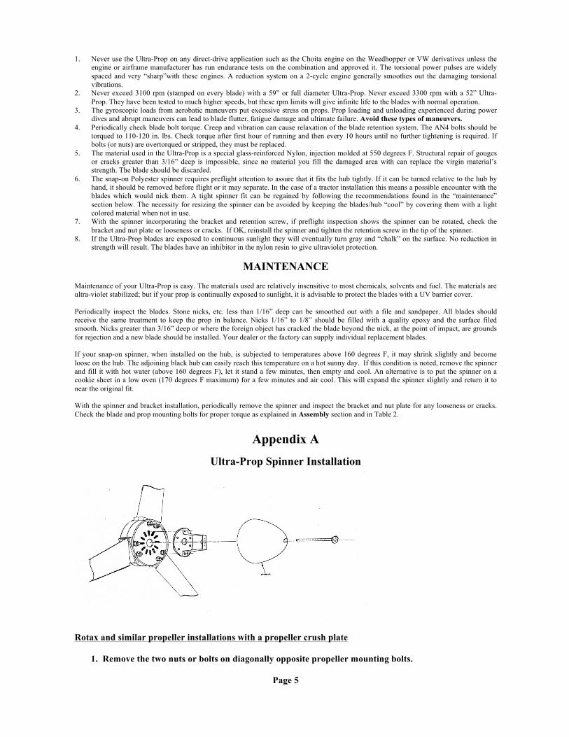
Ultra-Prop Spinner Installation
Rotax and similar propeller installations with a propeller crush plate 1. Remove the two nuts or bolts on diagonally opposite propeller mounting bolts.
Page 5
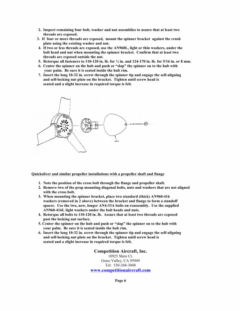
2. Inspect remaining four bolt, washer and nut assemblies to assure that at least two threads are exposed. 3. If four or more threads are exposed, mount the spinner bracket against the crush plate using the existing washer and nut. 4. If two or less threads are exposed, use the AN960L, light or thin washers, under the bolt head and nut when mounting the spinner bracket. Confirm that at least two threads are exposed outside the nut. 5. Retorque all fasteners to 110-120 in. lb. for ¼ in. and 124-170 in. lb. for 5/16 in. or 8 mm. 6. Center the spinner on the hub and push or “slap” the spinner on to the hub with your palm. Be sure it is seated inside the hub rim. 7. Insert the long 10-32 in. screw through the spinner tip and engage the self-aligning and self-locking nut plate on the bracket. Tighten until screw head is seated and a slight increase in required torque is felt.
Quicksilver and similar propeller installations with a propeller shaft and flange 1. Note the position of the cross bolt through the flange and propeller shaft. 2. Remove two of the prop mounting diagonal bolts, nuts and washers that are not aligned with the cross bolt. 3. When mounting the spinner bracket, place two standard (thick) AN960-416 washers (removed in 2 above) between the bracket and flange to form a standoff spacer. Use the two, new, longer AN4-33A bolts on reassembly. Use the supplied AN960-416L light washers under the bolt heads and nuts. 4. Retorque all bolts to 110-120 in. lb. Assure that at least two threads are exposed past the locking nut surface. 5. Center the spinner on the hub and push or “slap” the spinner on to the hub with your palm. Be sure it is seated inside the hub rim. 6. Insert the long 10-32 in. screw through the spinner tip and engage the self-aligning and self-locking nut plate on the bracket. Tighten until screw head is seated and a slight increase in required torque is felt.
Competition Aircraft, Inc. 10925 Shire Ct.
Grass Valley, CA 95949 Tel: 530-268-3048
www.competitionaircraft.com
Page 6