Embed Size (px)
Citation preview

1
A 64mW DNN-based Visual Navigation Enginefor Autonomous Nano-Drones
Daniele Palossi, Antonio Loquercio, Francesco Conti, Eric Flamand, Davide Scaramuzza, Luca Benini
Abstract—Fully-autonomous miniaturized robots (e.g., drones),with artificial intelligence (AI) based visual navigation capabilitiesare extremely challenging drivers of Internet-of-Things edge in-telligence capabilities. Visual navigation based on AI approaches,such as deep neural networks (DNNs) are becoming pervasive forstandard-size drones, but are considered out of reach for nano-drones with size of a few cm2. In this work, we present the first(to the best of our knowledge) demonstration of a navigationengine for autonomous nano-drones capable of closed-loop end-to-end DNN-based visual navigation. To achieve this goal we de-veloped a complete methodology for parallel execution of complexDNNs directly on-bard of resource-constrained milliwatt-scalenodes. Our system is based on GAP8, a novel parallel ultra-low-power computing platform, and a 27 g commercial, open-source CrazyFlie 2.0 nano-quadrotor. As part of our generalmethodology we discuss the software mapping techniques thatenable the state-of-the-art deep convolutional neural networkpresented in [1] to be fully executed on-board within a strict6 fps real-time constraint with no compromise in terms of flightresults, while all processing is done with only 64 mW on average.Our navigation engine is flexible and can be used to span a wideperformance range: at its peak performance corner it achieves18 fps while still consuming on average just 3.5% of the powerenvelope of the deployed nano-aircraft.
Index Terms—Unmanned Autonomous Vehicles, ConvolutionalNeural Networks, Ultra-low-power
I. INTRODUCTION
W ith the rise of the Internet-of-Things (IoT) era and rapiddevelopment of artificial intelligence (AI), embedded
systems ad-hoc programmed to act in relative isolation arebeing progressively replaced by AI-based sensor nodes thatacquire information, process and understand it, and use itto interact with the environment and with each other. The”ultimate” IoT node will be that which will be capable ofautonomously navigating the environment and, at the sametime, sensing, analyzing, and understanding it [2].
This work has been partially funded by projects EC H2020 HERCULES(688860), by the Swiss National Science Foundation under grant 162524(MicroLearn: Micropower Deep Learning), by the Swiss National Center ofCompetence Research (NCCR) Robotics and by the SNSF-ERC starting grant.
D. Palossi, F. Conti, E. Flamand and L. Benini are with the Inte-grated System Laboratory of ETH Zurich, ETZ, Gloriastrasse 35, 8092Zurich, Switzerland (e-mail: [email protected], [email protected],[email protected], [email protected]).
A. Loquercio and D. Scaramuzza are with the Robotic and PerceptionGroup, at both the Dep. of Informatics (University of Zurich) and the Dep.of Neuroinformatics (University of Zurich and ETH Zurich), Andreasstrasse15, 8050 Zurich, Switzerland.
F. Conti and L. Benini are also with the Department of Electrical, Electronicand Information Engineering of University of Bologna, Viale del Risorgimento2, 40136 Bologna, Italy (e-mail: [email protected], [email protected]).
E. Flamand is also with GreenWaves Technologies, PepiniereBerges, avenue des Papeteries, 38190 Villard-Bonnot, France (e-mail:[email protected]).
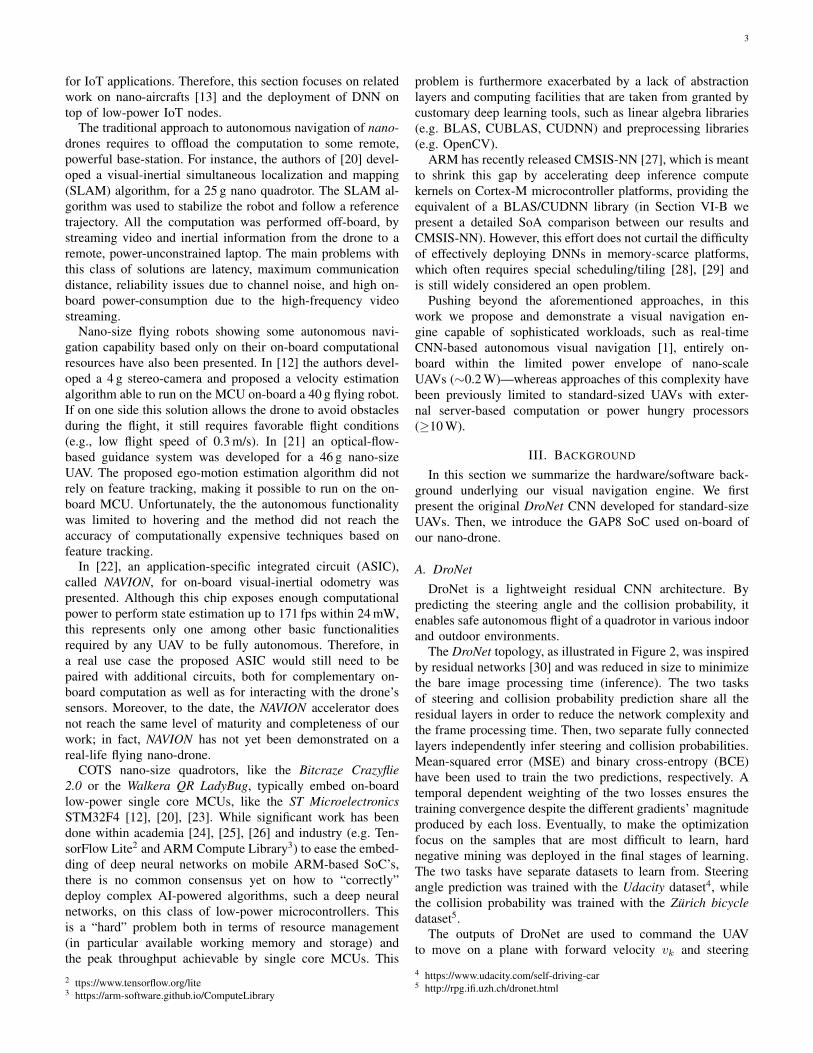
Fig. 1: Our prototype based on the COTS Crazyflie 2.0 nano-quadrotor extended with our PULP-Shield. The system is ableto run the DroNet [1] CNN for autonomous visual navigationup to 18 fps using only on-board resources.
Fully autonomous nano-scale unmanned aerial vehicles(UAVs) are a befitting embodiments for this class of smartsensors: with their speed and agility, they have the potentialto quickly collect information from both their on-board sensorsand from a plethora of devices deployed in the environment.Nano-UAVs could also perform advanced on-board analytics,to pre-select essential information before transmitting it tocentralized servers [3]. The tiny form-factor of nano-dronesis ideal both for indoor applications where they should safelyoperate near humans (for surveillance, monitoring, ambientawareness, interaction with smart environments, etc.) [4] andfor highly-populated urban areas, where they can exploitcomplementary sense-act capabilities to interact with the sur-roundings (e.g., smart-building, smart-cities, etc.) [5].
Commercial off-the-shelf (COTS) quadrotors have alreadystarted to enter the nano-scale, featuring only few centimetersin diameter and few tens of grams in weight [6]. How-ever, commercial nano-UAVs still lack the autonomy boastedby their larger counterparts [1], [7], [8], [9], since theircomputational capabilities, heavily constrained by their tinypower envelopes, have been considered so far to be totallyinadequate for the execution of sophisticated AI workloads,as summarized in Table I.
The traditional approach to autonomous navigation of an
arX
iv:1
805.
0183
1v2
[cs
.RO
] 1
5 Ja
n 20
19

2
TABLE I: Rotorcraft UAVs taxonomy by vehicle class-size.
Vehicle Class � : Weight [cm:kg] Power [W] On-board Device
std-size [10] ∼ 50 : ≥ 1 ≥ 100 Desktop
micro-size [11] ∼ 25 : ∼ 0.5 ∼ 50 Embedded
nano-size [12] ∼ 10 : ∼ 0.01 ∼ 5 MCU
pico-size [13] ∼ 2 : ≤ 0.001 ∼ 0.1 ULP
UAV is the so-called localization-mapping-planning cycle,which consists of estimating the robot motion using eitheroffboard (e.g. GPS [14]) or onboard sensors (e.g., visual-inertial sensors [15]), building a local 3D map of the envi-ronment, and planning a safe trajectory through it [9]. Thesemethods, however, are very expensive for computationally-constrained platforms. Recent results have shown that muchlighter algorithms, based on convolutional neural networks(CNNs), are sufficient for enabling basic reactive navigation ofsmall drones, even without a map of the environment [1], [16],[17], [18], [19]. However, their computational and power needsare unfortunately still above the allotted budget of currentnavigation engines of nano drones, which are based on simple,low-power microcontroller units (MCUs).
In Wood et al. [13], the authors indicate that, for small-size UAVs, the maximum power budget that can be spentfor on-board computation is 5% of the total, the rest beingused by the propellers (86%) and the low-level control parts(9%). The problem of bringing state-of-the-art navigationcapabilities on the challenging classes of nano- and pico-sizeUAVs is therefore strictly dependent on the development ofenergy-efficient and computationally capable hardware, highlyoptimized software and new classes of algorithms combinedtogether into a next-generation navigation engine. These con-straints and requirements depict the same scenario faced indeploying high level computation capabilities on IoT edge-nodes/sensors. Moreover, in the case of a flying miniaturerobot, the challenge is exacerbated by the strict real-timeconstraint dictated by the need of fast reaction time in orderto prevent collisions with dynamic obstacles.
Whereas standard-size UAVs with a power envelope ofseveral hundreds Watts have always been able to host powerfulhigh-end embedded computers like Qualcomm Snapdragon1,Odroid, NVIDIA Jetson TX1 and TX2, etc., most nano-sizedUAVs have been constrained by the capabilities of micro-controller devices capable to provide a few hundreds Mop/sat best. Therefore, CNN-based autonomous vision navigationwas so far considered to be out of reach for this class of drones.
In this work, we propose a novel visual navigation engineand a general methodology to deploy complex CNN on top ofCOTS resources-constrained computational edge-nodes suchas a nano-size flying robot. We present what, to the bestof our knowledge, is the first deployment of a State-of-the-Art (SoA), fully autonomous vision-based navigation systembased on deep learning on top of a UAV visual navigationengine consuming less than 284 mW at peak (64 mW in themost energy-efficient configuration), fully integrated and inclosed-loop control within an open source COTS CrazyFlie
1 https://developer.qualcomm.com/hardware/qualcomm-flight
2.0 nano-UAV. Our visual navigation engine, shown on thetop of the CrazyFlie 2.0 in Figure 1, leverages the Green-Waves Technologies GAP8 SoC, a high-efficiency embeddedprocessor taking advantage of the emerging parallel ultra-low-power (PULP) computing paradigm to enable the executionof complex algorithmic flows onto power-constrained devices,such as nano-scale UAVs.
This work provides several contributions beyond the SoA ofnano-scale UAVs and serves as a proof-of-concept for a largerclass of AI-based applications in the IoT field. In this work:
• we developed a general methodology for deploying SoAdeep learning algorithms on top of ultra-low power em-bedded computation nodes, as well as miniaturized robot;
• we adapted DroNet, the CNN-based approach for au-tonomous navigation proposed in Loquercio et al. [1] forstandard-sized UAVs, to the computational requirementsof a nano-sized UAV, such as fixed-point computation;
• we deployed DroNet on the PULP-shield, an ultra-lowpower visual navigation module featuring the GAP8 SoC,an ultra-low power camera and off-chip Flash/DRAMmemory; the shield is designed as a pluggable PCB forthe 27 g COTS CrazyFlie 2.0 nano-UAV;
• we demonstrate our methodology for the DroNet CNN,achieving comparable quality of results in terms of UAVcontrol with respect to the standard-sized baseline of [1]within an overall PULP-shield power budget of just64 mW, achieving a throughput of 6 fps and up to 18 fpswithin 284 mW;
• we field-prove our methodology presenting a closed-loop fully functional demonstration of vision-driven au-tonomous navigation relying only on on-board resources.
Our work demonstrates that parallel ultra-low power com-puting is a viable solution to deploy autonomous navigationcapabilities on-board nano-UAVs used as smart, mobile IoTendnodes, while at the same time showcasing a completehardware/software methodology to implement such complexworkloads on heavily power- and memory-constrained device.
The rest of the paper is organized as follows: Section IIprovides the SoA overview both in term of nano-UAVs andlow-power IoT. In Section III introduces the software/hardwarebackground of our work. Section IV presents in detail ourCNN mapping methodology, including software tools andoptimizations. Section V discusses the design of the vi-sual navigation engine. Section VI-B shows the experimentalevaluation of the work, considering both performance andpower consumption, comparing our results with the SoA andalso evaluating the final control accuracy. Finally, SectionVIIconcludes the paper.
II. RELATED WORK
The development of the IoT is fueling a trend towardedge computing, to improve scalability, robustness, security[2]. While today’s IoT edge nodes are usually stationary, au-tonomous nano-UAVs can be seen as perfect examples of next-generation IoT end-nodes, with high mobility and requiring anunprecedented level of on-board intelligence. The goal of thiswork is to make SoA visual autonomous navigation compatiblewith ultra-low power nano-drones, unlocking their deployment
3
for IoT applications. Therefore, this section focuses on relatedwork on nano-aircrafts [13] and the deployment of DNN ontop of low-power IoT nodes.
The traditional approach to autonomous navigation of nano-drones requires to offload the computation to some remote,powerful base-station. For instance, the authors of [20] devel-oped a visual-inertial simultaneous localization and mapping(SLAM) algorithm, for a 25 g nano quadrotor. The SLAM al-gorithm was used to stabilize the robot and follow a referencetrajectory. All the computation was performed off-board, bystreaming video and inertial information from the drone to aremote, power-unconstrained laptop. The main problems withthis class of solutions are latency, maximum communicationdistance, reliability issues due to channel noise, and high on-board power-consumption due to the high-frequency videostreaming.
Nano-size flying robots showing some autonomous navi-gation capability based only on their on-board computationalresources have also been presented. In [12] the authors devel-oped a 4 g stereo-camera and proposed a velocity estimationalgorithm able to run on the MCU on-board a 40 g flying robot.If on one side this solution allows the drone to avoid obstaclesduring the flight, it still requires favorable flight conditions(e.g., low flight speed of 0.3 m/s). In [21] an optical-flow-based guidance system was developed for a 46 g nano-sizeUAV. The proposed ego-motion estimation algorithm did notrely on feature tracking, making it possible to run on the on-board MCU. Unfortunately, the the autonomous functionalitywas limited to hovering and the method did not reach theaccuracy of computationally expensive techniques based onfeature tracking.
In [22], an application-specific integrated circuit (ASIC),called NAVION, for on-board visual-inertial odometry waspresented. Although this chip exposes enough computationalpower to perform state estimation up to 171 fps within 24 mW,this represents only one among other basic functionalitiesrequired by any UAV to be fully autonomous. Therefore, ina real use case the proposed ASIC would still need to bepaired with additional circuits, both for complementary on-board computation as well as for interacting with the drone’ssensors. Moreover, to the date, the NAVION accelerator doesnot reach the same level of maturity and completeness of ourwork; in fact, NAVION has not yet been demonstrated on areal-life flying nano-drone.
COTS nano-size quadrotors, like the Bitcraze Crazyflie2.0 or the Walkera QR LadyBug, typically embed on-boardlow-power single core MCUs, like the ST MicroelectronicsSTM32F4 [12], [20], [23]. While significant work has beendone within academia [24], [25], [26] and industry (e.g. Ten-sorFlow Lite2 and ARM Compute Library3) to ease the embed-ding of deep neural networks on mobile ARM-based SoC’s,there is no common consensus yet on how to “correctly”deploy complex AI-powered algorithms, such a deep neuralnetworks, on this class of low-power microcontrollers. Thisis a “hard” problem both in terms of resource management(in particular available working memory and storage) andthe peak throughput achievable by single core MCUs. This2 ttps://www.tensorflow.org/lite3 https://arm-software.github.io/ComputeLibrary
problem is furthermore exacerbated by a lack of abstractionlayers and computing facilities that are taken from granted bycustomary deep learning tools, such as linear algebra libraries(e.g. BLAS, CUBLAS, CUDNN) and preprocessing libraries(e.g. OpenCV).
ARM has recently released CMSIS-NN [27], which is meantto shrink this gap by accelerating deep inference computekernels on Cortex-M microcontroller platforms, providing theequivalent of a BLAS/CUDNN library (in Section VI-B wepresent a detailed SoA comparison between our results andCMSIS-NN). However, this effort does not curtail the difficultyof effectively deploying DNNs in memory-scarce platforms,which often requires special scheduling/tiling [28], [29] andis still widely considered an open problem.
Pushing beyond the aforementioned approaches, in thiswork we propose and demonstrate a visual navigation en-gine capable of sophisticated workloads, such as real-timeCNN-based autonomous visual navigation [1], entirely on-board within the limited power envelope of nano-scaleUAVs (∼0.2 W)—whereas approaches of this complexity havebeen previously limited to standard-sized UAVs with exter-nal server-based computation or power hungry processors(≥10 W).
III. BACKGROUND
In this section we summarize the hardware/software back-ground underlying our visual navigation engine. We firstpresent the original DroNet CNN developed for standard-sizeUAVs. Then, we introduce the GAP8 SoC used on-board ofour nano-drone.
A. DroNetDroNet is a lightweight residual CNN architecture. By
predicting the steering angle and the collision probability, itenables safe autonomous flight of a quadrotor in various indoorand outdoor environments.
The DroNet topology, as illustrated in Figure 2, was inspiredby residual networks [30] and was reduced in size to minimizethe bare image processing time (inference). The two tasksof steering and collision probability prediction share all theresidual layers in order to reduce the network complexity andthe frame processing time. Then, two separate fully connectedlayers independently infer steering and collision probabilities.Mean-squared error (MSE) and binary cross-entropy (BCE)have been used to train the two predictions, respectively. Atemporal dependent weighting of the two losses ensures thetraining convergence despite the different gradients’ magnitudeproduced by each loss. Eventually, to make the optimizationfocus on the samples that are most difficult to learn, hardnegative mining was deployed in the final stages of learning.The two tasks have separate datasets to learn from. Steeringangle prediction was trained with the Udacity dataset4, whilethe collision probability was trained with the Zurich bicycledataset5.
The outputs of DroNet are used to command the UAVto move on a plane with forward velocity vk and steering
4 https://www.udacity.com/self-driving-car5 http://rpg.ifi.uzh.ch/dronet.html

4
3x33x3
/2BN
BN
1x1
/2
3x33x3
/2BN
BN
1x1
/25x5
/2
3x3
/2/2 3x33x3
/2BN
BN
1x1
/2
RES BLOCK 1
3x3
RES BLOCK 2 RES BLOCK 3
100×100×32 50×50×32 25×25×32 13×13×64 7×7×128
NxN
/S Convolution/S: stride factorNxN: filter size
/S
NxN
Max-pooling/S: stride factorNxN: pool size
BN
BatchNormalization
ReLu Sum Dropout Fullyconnected
Sigmoid
7×7×12813×13×6425×25×32Steering angle
by-pass by-pass by-pass
Prob. collision
Input image200x200x1
Fig. 2: DroNet [1] topology.
angle θk. More specifically, the low-pass filtered probabilityof collision is used to modulate the UAV forward velocity,while the low-pass filtered steering angle is converted to thedrone’s yaw control. The result is a single relatively shallownetwork that processes all visual information and directlyproduces control commands for a flying drone. Learning thecoupling between perception and control end-to-end providesseveral advantages, such as a simple, lightweight system andhigh generalization abilities. Indeed, the method was shownto function not only in urban environments but also on aset of new application spaces without any initial knowledgeabout them [1]. More specifically, even without a map of theenvironment, the approach generalizes very well to scenarioscompletely unseen at training time, including indoor corridors,parking lots, and high altitudes.
B. GAP8 ArchitectureOur deployment target for the bulk of the DroNet com-
putation is GAP8, a commercial embedded RISC-V multi-core processor derived from the PULP open source project6.At its heart, GAP8 is composed by an advanced RISC-Vmicrocontroller unit coupled with a programmable octacoreaccelerator with RISC-V cores enhanced for digital signalprocessing and embedded deep inference.
SoC
Inte
rco
nnec
t
PULP CLUSTER
Shared-L1 Interconnect
Core0 Core1 Core2 Core3
Core7Core6Core5Core4
Shared L1 Memory64KB
Shared Instruction Cache
HWSync
DBGUnit
L2 Memory512KB
μD
MA FABRIC
CTRL
I $
L1
ROM
CLKGen
DBG
DC/DC
LVDS
UART
SPI
I2S
I2C
CPI
HYPER
GPIO
JTAG
PMU
RTC
DM
A
Fig. 3: Architecture of the GAP8 embedded processor.
Figure 3 shows the architecture of GAP8 in detail. Theprocessor is composed by two separate power and clockdomains, the FABRIC CTRL (FC) and the CLUSTER (CL). TheFC is an advanced microcontroller unit feturing a single RISC-V core coupled with 512 kB of SRAM (L2 memory). The FCuses an in-order, DSP-extended four-stage microarchitecture
6 http://pulp-platform.org
implementing the RISC-V instruction set architecture [31].The core supports the RV32IMC instruction set consistingof the standard ALU instructions plus the multiply instruc-tion, with the possibility to execute compressed code. Inaddition to this, the core is extended to include a register-register multiply-accumulate instruction, packed SIMD (singleinstruction multiple-data) DSP instructions (e.g. fixed-pointdot product), bit manipulation instructions and two hardwareloops. Moreover, the SoC features an autonomous multi-channel I/O DMA controller (µDMA) [32] capable of trans-fering data between a rich set of peripherals (QSPI, I2S, I2C,HyperBus, Camera Parallel Interface) and the L2 memory withno involvement of the FC. The HyperBus and QSPI interfacescan be used to connect GAP8 with an external DRAM orFlash memory, effectively extending the memory hierarchywith an external L3 having a bandwidth of 333 MB/s andcapacity up to 128 Mbit. Finally, the GAP8 SoC also includesa DC/DC converter converting the battery voltage down to therequired operating voltage directly on chip, as well as twoseparate frequency-locked loops (FLL) for ultra-low powerclock generation [33].
The CLUSTER is dedicated to the acceleration of com-putationally intensive tasks. It contains eight RISC-V cores(identical to the one used in the FC) sharing a 64 kB multi-banked shared L1 scratchpad memory through a low-latency,high-throughput logarithmic interconnect [34]. The shared L1memory supports single-cycle concurrent access from differentcores requesting memory locations on separate banks and astarvation-free protocol in case of bank contentions (typically<10% on memory-intensive kernels). The eight cores are fedwith instruction streams from a single shared, multi-ported I-cache to maximize the energy efficiency on data-parallel code.A cluster DMA controller is used to transfer data between theshared L1 scratchpad and the L2 memory; it is capable of 1Dand 2D bulk memory transfer on the L2 side (only 1D onthe L1 side). A dedicated hardware synchronizer is used tosupport fast event management and parallel thread dispatch-ing/synchronization to enable ultra-fine grain parallelism onthe cluster cores. CLUSTER and FABRIC CTRL share a singleaddress space and communicate with one another by means oftwo 64-bit AXI ports, one per direction. A software runtimeresident in the FC overviews all tasks offloaded to the CL andto the µDMA. On turn, a low-overhead runtime on the CLcores exploits the hardware synchronizer to implement shared-memory parallelism in the fashion of OpenMP [35].

5
TABLE II: DroNet accuracy on PULP. In bold the configuration used for the final deployment.
Training Inference - Fixed16
Dataset Max-Pooling Data TypeOriginal Dataset HiMax Dataset
EVA RMSE Accuracy F1-score Accuracy F1-score
Original
3× 3 Float32 0.758 0.109 0.952 0.888 0.859 0.7523× 3 Fixed16 0.746 0.115 0.946 0.878 0.841 0.7982× 2 Float32 0.766 0.105 0.945 0.875 0.845 0.7122× 2 Fixed16 0.795 0.097 0.935 0.857 0.873 0.774
Original + HiMax
3× 3 Float32 0.764 0.104 0.949 0.889 0.927 0.8843× 3 Fixed16 0.762 0.109 0.956 0.894 0.918 0.8702× 2 Float32 0.747 0.109 0.964 0.916 0.900 0.8312 × 2 Fixed16 0.732 0.110 0.977 0.946 0.891 0.821
IV. CNN MAPPING METHODOLOGY
In this section, we discuss and characterize the mainmethodological aspects related to the deployment of DroNeton top of the GAP8 embedded processor. This task showcasesall the main challenges for a typical deep learning applicationrunning on resources-constrained embedded IoT node. There-fore, while our visual navigation engine is application-specific,the underlying methodology we present in the following of thissection is general in nature and could be applied also to otherresource-bound embedded systems where computationally in-tense tasks have to be performed under a real-time constrainton a parallel architecture.
A. Deploying DroNet on GAP8
Following an initial characterization phase, we calculatedthe original convolutional neural network (CNN) to involve∼41 MMAC operations per frame (accounting only for con-volutional layers) and more than 1 MB of memory neededonly to store the network’s weights, yielding a baseline for theamount of resources required on our navigation engine7. Tosuccessfully deploy the CNN on top of GAP8, the executionof DroNet has to fit within the strict real-time constraintsdictated by the target application, while respecting the boundsimposed by the on-chip and on-board resources. Specifically,these constraints can be resumed in three main points:
• the minimum real-time frame-rate required to select a newtrajectory on-the-fly or to detect a suspected obstacle intime to prevent a potential collision;
• the native quality-of-results must be maintained whenusing an embedded ultra-low power camera (in our pro-totype, the HiMax – see Section V for details) instead ofthe high resolution camera used by the original DroNet;
• the amount of available memory on the GAP8 SoC, whereas reported in Section III-B we can rely on 512 kB of L2SRAM and 64 kB of shared L1 scratchpad (TCDM), setsan upper bound to the size of operating set and dictatesad-hoc memory management strategy.
Therefore, it is clear there is a strong need for a strategyaimed at reducing the memory footprint and computational
7 The baseline MMAC count does not correspond to the final implementa-tion’s instruction count, because it does not account for implementation detailssuch as data marshaling operations to feed the processing elements; however,it can be used to set an upper bound to the minimum execution performancethat is necessary to deploy DroNet at a given target frame rate.
load to more easily fit within the available resources, whileexploiting the architectural parallelism at best to meet the real-time constraint. Therefore, the original DroNet network [1]has been modified to ease its final deployment; we operatedincrementally on the model and training flow provided by theoriginal DroNet, based on Keras/TensorFlow8.
The first change we performed is the reduction of thenumerical representation of weights and activations from thenative one, 32-bit floating point (Float32), down to amore economical and hardware-friendly 16-bit fixed pointone (Fixed16) that is better suited for the deployment onany MUC-class processor without floating point unit (FPU),like in our GAP8 SoC. By analyzing the native Float32network post-training, we determined that a dynamic rangeof ±8 is sufficient to represent all weights and intermediateactivations with realistic inputs. Accordingly, we selected aFixed16 Q4.12 representation, using 4 bits for the integerpart (including sign) and 12 bits for the fractionary part ofboth activations and weights (rounding down to a precision of2−12). Then, we retrained the network from scratch replacingthe native convolutional layers from Keras to make them“quantization-aware”, using the methodology proposed byHubara et al. [36].
The second significant change with respect to the originalversion of DroNet is the extension of the collision datasetused in [1] (named Original dataset) with ∼ 1300 images(1122 for training and 228 for test/validation) acquired withthe same camera that is available on-board the nano-drone(named HiMax dataset). Fine-tuning approaches, like datasetextension, have proved to be particularly effective at improvingnetwork generalization capability [37]. In our case, the originaldataset is built starting form high-resolution color cameraswhose images are significantly different from the ones ac-quired by the ULP low-resolution grayscale camera availablein our navigation engine, particularly in terms of contrast.Therefore, we extended the training set and we evaluate ourCNN for both datasets separately. Finally, we modified thereceptive field of max-pooling layers from 3×3 to 2×2, whichyields essentially the same final results while reducing theexecution time of max-pooling layers by 2.2× and simplifyingtheir final implementation on GAP8.
Table II summarizes the results in terms of accuracy for allthese changes. Explained Variance9 (EVA) and Root-Mean-8 https://github.com/uzh-rpg/rpg public dronet9 EVA =
V ar[ytrue−ypred]
V ar[ytrue]

6
Square Error (RMSE) refer to the regression problem (i.e.,steering angle) whereas Accuracy and F1-score10 are related tothe classification problem (i.e., collision probability), evaluatedon both the Original and HiMax datasets. Regarding theOriginal dataset, it is clear that the proposed modifications arenot penalizing the overall network’s capabilities. Moreover,fine-tuning increases performance for almost all cases (bothregression and classification). Considering the test on theHiMax dataset, there is a clear improvement in term ofcollision accuracy when training is done with the extendeddataset. In fact, if we consider paired configurations, the fine-tuned one based is always outperforming its counterpart, up to8% in accuracy (i.e., max-pooling 3×3, Fixed16). In Table IIwe also highlight (in bold) the scores achieved by the finalversion of DroNet deployed on GAP8.
B. AutoTilerOne of the biggest constraints in ULP embedded SoC’s
without caches is the explicit management of the memoryhierarchy; that is, how to marshal data between the bigger - andslower - memories and the smaller - but faster - ones tightlycoupled to the processing elements. A common technique istiling [38], which involves i) partitioning the input and outputdata spaces in portions or tiles small enough to fit within thesmallest memory in the hierarchy (in our case, the sharedL1) and ii) setting up an outer loop iterating on tiles, witheach iteration comprising the loading of an input tile into theL1, the production of an output tile, and the storage of theoutput tile into the higher levels of the memory hierarchy.Tiling is particularly effective for algorithms like deep neuralnetworks exposing very regular execution and data accesspatterns. As part of this work, we propose a tiling methodologythat optimizes memory utilization on GAP8, while at the sametime relieving the user from tedious and error-prone manualcoding of the tiling loop and of the data movement mechanism.
L2 Memory (512KB) L1 Memory (64KB)
Input
tenso
r
DMA
DMA
DMA
Outp
ut
tenso
rFi
lters
Output tile
tile 2
tile 1
tile 2
tile 3
tile 4
KinWin
Hin
tile 1
tile 2
tile 3
tile 4
KoutWout
Hout
Kin × Kout
convFilter
Hf
Wf
Input tile
tile 2
Fig. 4: Convolutional layer tiling.
Considering Figure 4 as a reference, each layer in a CNNoperates on a three-dimensional input tensor representing afeature space (with one feature map per channel) and producesa new 3D tensor of activations as output. Convolutional layers,in particular, are composed of a linear transformation thatmaps Kin input feature maps into Kout output feature maps by
10 F-1 = 2 precision×recallprecision+recall
means of Kin×Kout convolutional filters (or weight matrices).Therefore, in any convolutional layer we can identify threedifferent data spaces which can be partitioned in tiles in one ormore of the three dimensions (i.e., W , H and K in Figure 4).Similar considerations can be made also for the other layersin a CNN, allowing to treat them in the same fashion.
As the design space defined by all possible tiling schemes isvery large, we developed a tool called AutoTiler to help explorea subset of this space, choose an optimal tiling configuration,and produce C wrapping code that orchestrates the computa-tion in a pipelined fashion as well as double-buffered memorytransfers, taking advantage of the cluster DMA controller toefficiently move data between the L2 and L1 memories. Thefundamental unit of computation assumed by the AutoTilertool is the basic kernel, a function assuming that all itsworking data is already located in the L1 shared memory.Examples of basic kernels include convolution, max-pooling,ReLU rectification, addition. To map the overall high-levelalgorithm to a set of basic kernels that operate iteratively ontiles, the AutoTiler introduces a second level of abstraction: thenode kernel. The structure of the target algorithm is coded bythe developer as a dependency graph, where each node (a nodekernel) is a composition of one or more basic kernels togetherwith a specification of the related iteration space over W , H ,Kin, Kout. For example, a node kernel for a convolutionallayer can be composed of a first basic kernel for setting theinitial bias, a central one to perform convolutions and a finalone for ReLU rectification: in the prologue, body and epilogue,respectively. The AutoTiler treats the tiling of each nodekernel as an independent optimization problem constrainedby the node kernel specification and the memory sizes. Thisapproach allows to build complex execution flows reusinghand-optimized basic kernels and abstracting the underneathcomplexity from the developer.
C. Tiling, Parallelization & Optimization
As introduced in Section III, the GAP8 SoC features 8+1RISC-V cores with DSP-oriented extensions. To develop anoptimized, high-performance and energy-efficient applicationfor GAP8 and meet the required real-time constraint, it isparamount that the most computationally intense kernels ofthe algorithm are parallelized to take advantage of the 8-corecluster and are fully using the available specialized instruc-tions. For the purpose of this work, we used the AutoTilerto fully implement the structure of the modified DroNet,therefore these optimization steps are reduced to hand-tunedparallelization and optimization of the basic kernels.
To exploit the available computational/memory resourcesat best, we constrain the AutoTiler to target the followinggeneral scheme: the input tensor is tiled along the Hin
and Kin dimensions, while the output tensor is tiled alongHout and Kout ones. The stripes along Hin are partiallyoverlapped with one another to take into account the receptivefield of convolutional kernels at the tile border. Execution ofthe node kernel happens in either a spatial or feature-wisefashion, which differ in the ordering of the tiling loops andin the parallelization scheme that is applied. In the spatialscheme, work is split among parallel cores along the Wout

7
Listing 1 Example of spatial execution scheme. x, w, y arethe multi-dimensional input, weight and output tensors in L2memory; x, w and y are their respective tiles in L1 memory.
INTERNET OF THINGS JOURNAL, VOL. XX, NO. YY, JANUARY 2019 7
Listing 1 Example of spatial execution scheme. x, w, y arethe multi-dimensional input, weight and output tensors in L2memory; bx, bw and by are their respective tiles in L1 memory.# weight DMA-inDMA_Copy( bw w)for t in range(nb_tiles_H): # tiling over H
# prologue operation (set bias value)by BasicKernel_SetBias(by)for j in range(nb_tiles_Kin): # tiling over Kin
# input tile DMA-inDMA_Copy(bx x[j, t])for i in range(Kout):
# body operation (convolution)by BasicKernel_Conv_Spatial(by)
by BasicKernel_ReLU(by)# output tile DMA-outDMA_Copy(y[i, t] by)
Listing 2 Example of feature-wise execution scheme. x, w,y are the multi-dimensional input, weight and output tensorsin L2 memory; bx, bw and by are their respective tiles in L1memory.for i in range(nb_tiles_Kout): # tiling over Kout
# weight DMA-inDMA_Copy( bw w[i])# prologue operation (set bias value)by BasicKernel_SetBias(by)for j in range(nb_tiles_Kin): # tiling over Kin
# input tile DMA-inDMA_Copy(bx x[j])# body operation (convolution)by BasicKernel_Conv_FeatWise( bw, bx, by)
# epilogue operation (ReLU)by BasicKernel_ReLU(by)# output tile DMA-outDMA_Copy(y[i] by)
dimension; Figure 4 and 5-A refer to this scheme, which is alsoexemplified in Listing 1. In the feature-wise scheme, which weonly apply on full feature maps (i.e. the number of tiles in theHout direction is 1), work is split among cores along the Kout
dimension; this scheme is shown in Figure 5-B and Listing 2.The choice of one scheme over the other is influenced mostlyby the parallelization efficiency: after an exploration phase,we found the best performance arised when using the spatialscheme for the first node kernel of DroNet (first convolution+ max-pooling), while using the feature-wise approach for therest. This choice is related to the fact that in deeper layers thefeature map size drops rapidly and the spatial scheme becomessuboptimal, because the width of each stripe turns too smallto achieve full utilization of the cores.
GAP8 - CLUSTER
0
1
2
3
4
5
6
7
Spatial scheme
A Output tensor
Wout
01
23
45
67
Kout-1
Kout
Hou
t
Feature-wise scheme
BOutput tensorCores
Kout
Hou
t
Wout
0 1 2 3 4 5 6 7
Fig. 5: Parallelization schemes utilized in the DroNet layers fordeployment on GAP8; the different colors represent allocationto a different core.
To further optimize the DroNet execution, we madeuse of all the optimized signal processing instructionsavailable in GAP8. These include packed-SIMD in-structions capable of exploiting sub-word parallelism, aswell as bit-level manipulation and shuffling, which canbe accessed by means of compiler intrinsics such as__builtin_pulp_dotsp2 (for 16-bit dot product with 32-bitaccumulation), __builtin_shuffle (permutation of elementswithin two input vectors), __builtin_pulp_pack2 (packingtwo scalars into a vector).
D. L2 Memory Management Strategy
Given i) the residual-network topology of DroNet, whichrequires to increase the lifetime of the output tensors of someof the layers (due to bypass layers), and ii) the “scarsity” ofL2 memory as a resource to store all weights and temporaryfeature maps (we would need more than 1 MB in view of512 kB available), an ad-hoc memory management strategy forthe L2 memory is required, similar to what is done betweenL2 and L1 using the GAP8 AutoTiler. Due to the high energycost of data transfers between L3 and L2, the strategy needsto be aimed at the maximization of the L2 reuse.
At boot time, before the actual computation loop starts, i)we load all the weights, stored in the external flash memoryas binary files, in the L3 DRAM memory and ii) we callfrom the fabric controller the runtime allocator to reserve twoL2 allocation stacks (shown in Figure 7) where intermediatebuffers will be allocated and deallocated in a linear fashion.The choice to use two allocation stacks instead of a singleone is due to the fact that in the latter case, we would needto keep alive up to 665 kB in L2 due to data dependencies,which is more than the available space. Our allocation strategysimply updates the pointer of the next free location in the pre-allocated L2 stack, avoiding the runtime overhead of libraryallocation/free functions. We differentiate our strategy betweenweights and feature maps: for the former, we allocate spacejust before their related layer and deallocate it just after thelayer execution, as also shown in the pseudo-code blocks ofFigure 6. For the latter, due to the residual network bypasses,we often have to prolongate the lifetime of a feature mapduring the execution of the two following layers (node kernelsin Figure 6). Therefore, for each RES block there will be anamount of time where 3 tensors have to be stored at the sametime.
Figure 6 shows the full execution flow of DroNet relatedto our solution, annotated with the sequence of node kernelsand the L3/L2 memory management blocks. For the sake ofreadability, in Figure 6, we report only the first RES block,but this can be generalized also to the others with few minormodifications and updating input, output and weights id. Inthe pseudo-code of Figure 6 the second parameter of theAlloc and Free function specifies the allocation buffer(i.e., Allocation stack 0 or Allocation stack 1in Figure 7). Note that, the µDMA copies the weights fromL3 to L2 just after the destination L2 area is allocated. Thebuffers’ memory allocation sequence is reported in Figure 7(from left to right) for the entire DroNet execution. Thecolumns of the two stacks represent the data needed at each
Listing 2 Example of feature-wise execution scheme. x, w,y are the multi-dimensional input, weight and output tensorsin L2 memory; x, w and y are their respective tiles in L1memory.
INTERNET OF THINGS JOURNAL, VOL. XX, NO. YY, JANUARY 2019 7
Listing 1 Example of spatial execution scheme. x, w, y arethe multi-dimensional input, weight and output tensors in L2memory; bx, bw and by are their respective tiles in L1 memory.# weight DMA-inDMA_Copy( bw w)for t in range(nb_tiles_H): # tiling over H
# prologue operation (set bias value)by BasicKernel_SetBias(by)for j in range(nb_tiles_Kin): # tiling over Kin
# input tile DMA-inDMA_Copy(bx x[j, t])for i in range(Kout):
# body operation (convolution)by BasicKernel_Conv_Spatial(by)
by BasicKernel_ReLU(by)# output tile DMA-outDMA_Copy(y[i, t] by)
Listing 2 Example of feature-wise execution scheme. x, w,y are the multi-dimensional input, weight and output tensorsin L2 memory; bx, bw and by are their respective tiles in L1memory.for i in range(nb_tiles_Kout): # tiling over Kout
# weight DMA-inDMA_Copy( bw w[i])# prologue operation (set bias value)by BasicKernel_SetBias(by)for j in range(nb_tiles_Kin): # tiling over Kin
# input tile DMA-inDMA_Copy(bx x[j])# body operation (convolution)by BasicKernel_Conv_FeatWise( bw, bx, by)
# epilogue operation (ReLU)by BasicKernel_ReLU(by)# output tile DMA-outDMA_Copy(y[i] by)
dimension; Figure 4 and 5-A refer to this scheme, which is alsoexemplified in Listing 1. In the feature-wise scheme, which weonly apply on full feature maps (i.e. the number of tiles in theHout direction is 1), work is split among cores along the Kout
dimension; this scheme is shown in Figure 5-B and Listing 2.The choice of one scheme over the other is influenced mostlyby the parallelization efficiency: after an exploration phase,we found the best performance arised when using the spatialscheme for the first node kernel of DroNet (first convolution+ max-pooling), while using the feature-wise approach for therest. This choice is related to the fact that in deeper layers thefeature map size drops rapidly and the spatial scheme becomessuboptimal, because the width of each stripe turns too smallto achieve full utilization of the cores.
GAP8 - CLUSTER
0
1
2
3
4
5
6
7
Spatial scheme
A Output tensor
Wout
01
23
45
67
Kout-1
Kout
Hou
t
Feature-wise scheme
BOutput tensorCores
Kout
Hou
t
Wout
0 1 2 3 4 5 6 7
Fig. 5: Parallelization schemes utilized in the DroNet layers fordeployment on GAP8; the different colors represent allocationto a different core.
To further optimize the DroNet execution, we madeuse of all the optimized signal processing instructionsavailable in GAP8. These include packed-SIMD in-structions capable of exploiting sub-word parallelism, aswell as bit-level manipulation and shuffling, which canbe accessed by means of compiler intrinsics such as__builtin_pulp_dotsp2 (for 16-bit dot product with 32-bitaccumulation), __builtin_shuffle (permutation of elementswithin two input vectors), __builtin_pulp_pack2 (packingtwo scalars into a vector).
D. L2 Memory Management Strategy
Given i) the residual-network topology of DroNet, whichrequires to increase the lifetime of the output tensors of someof the layers (due to bypass layers), and ii) the “scarsity” ofL2 memory as a resource to store all weights and temporaryfeature maps (we would need more than 1 MB in view of512 kB available), an ad-hoc memory management strategy forthe L2 memory is required, similar to what is done betweenL2 and L1 using the GAP8 AutoTiler. Due to the high energycost of data transfers between L3 and L2, the strategy needsto be aimed at the maximization of the L2 reuse.
At boot time, before the actual computation loop starts, i)we load all the weights, stored in the external flash memoryas binary files, in the L3 DRAM memory and ii) we callfrom the fabric controller the runtime allocator to reserve twoL2 allocation stacks (shown in Figure 7) where intermediatebuffers will be allocated and deallocated in a linear fashion.The choice to use two allocation stacks instead of a singleone is due to the fact that in the latter case, we would needto keep alive up to 665 kB in L2 due to data dependencies,which is more than the available space. Our allocation strategysimply updates the pointer of the next free location in the pre-allocated L2 stack, avoiding the runtime overhead of libraryallocation/free functions. We differentiate our strategy betweenweights and feature maps: for the former, we allocate spacejust before their related layer and deallocate it just after thelayer execution, as also shown in the pseudo-code blocks ofFigure 6. For the latter, due to the residual network bypasses,we often have to prolongate the lifetime of a feature mapduring the execution of the two following layers (node kernelsin Figure 6). Therefore, for each RES block there will be anamount of time where 3 tensors have to be stored at the sametime.
Figure 6 shows the full execution flow of DroNet relatedto our solution, annotated with the sequence of node kernelsand the L3/L2 memory management blocks. For the sake ofreadability, in Figure 6, we report only the first RES block,but this can be generalized also to the others with few minormodifications and updating input, output and weights id. Inthe pseudo-code of Figure 6 the second parameter of theAlloc and Free function specifies the allocation buffer(i.e., Allocation stack 0 or Allocation stack 1in Figure 7). Note that, the µDMA copies the weights fromL3 to L2 just after the destination L2 area is allocated. Thebuffers’ memory allocation sequence is reported in Figure 7(from left to right) for the entire DroNet execution. Thecolumns of the two stacks represent the data needed at each
dimension; Figure 4 and 5-A refer to this scheme, which is alsoexemplified in Listing 1. In the feature-wise scheme, which weonly apply on full feature maps (i.e. the number of tiles in theHout direction is 1), work is split among cores along the Kout
dimension; this scheme is shown in Figure 5-B and Listing 2.The choice of one scheme over the other is influenced mostlyby the parallelization efficiency: after an exploration phase,we found the best performance arised when using the spatialscheme for the first node kernel of DroNet (first convolution+ max-pooling), while using the feature-wise approach for therest. This choice is related to the fact that in deeper layers thefeature map size drops rapidly and the spatial scheme becomessuboptimal, because the width of each stripe turns too smallto achieve full utilization of the cores.
To further optimize the DroNet execution, we madeuse of all the optimized signal processing instructionsavailable in GAP8. These include packed-SIMD in-structions capable of exploiting sub-word parallelism, aswell as bit-level manipulation and shuffling, which canbe accessed by means of compiler intrinsics such as__builtin_pulp_dotsp2 (for 16-bit dot product with 32-bitaccumulation), __builtin_shuffle (permutation of elementswithin two input vectors), __builtin_pulp_pack2 (packingtwo scalars into a vector).
GAP8 - CLUSTER
0
1
2
3
4
5
6
7
Spatial scheme
A Output tensor
Wout
01
23
45
67
Kout-1
Kout
Hout
Feature-wise scheme
BOutput tensorCores
Kout
Hout
Wout
0 1 2 3 4 5 6 7
Fig. 5: Parallelization schemes utilized in the DroNet layers fordeployment on GAP8; the different colors represent allocationto a different core.
D. L2 Memory Management Strategy
Given i) the residual-network topology of DroNet, whichrequires to increase the lifetime of the output tensors of someof the layers (due to bypass layers), and ii) the “scarsity” ofL2 memory as a resource to store all weights and temporaryfeature maps (we would need more than 1 MB in view of512 kB available), an ad-hoc memory management strategy forthe L2 memory is required, similar to what is done betweenL2 and L1 using the GAP8 AutoTiler. Due to the high energycost of data transfers between L3 and L2, the strategy needsto be aimed at the maximization of the L2 reuse.
At boot time, before the actual computation loop starts, i)we load all the weights, stored in the external flash memoryas binary files, in the L3 DRAM memory and ii) we callfrom the fabric controller the runtime allocator to reserve twoL2 allocation stacks (shown in Figure 7) where intermediatebuffers will be allocated and deallocated in a linear fashion.The choice to use two allocation stacks instead of a singleone is due to the fact that in the latter case, we would needto keep alive up to 665 kB in L2 due to data dependencies,which is more than the available space. Our allocation strategysimply updates the pointer of the next free location in the pre-allocated L2 stack, avoiding the runtime overhead of libraryallocation/free functions. We differentiate our strategy betweenweights and feature maps: for the former, we allocate spacejust before their related layer and deallocate it just after thelayer execution, as also shown in the pseudo-code blocks ofFigure 6. For the latter, due to the residual network bypasses,we often have to prolongate the lifetime of a feature mapduring the execution of the two following layers (node kernelsin Figure 6). Therefore, for each RES block there will be anamount of time where 3 tensors have to be stored at the sametime.
Figure 6 shows the full execution flow of DroNet relatedto our solution, annotated with the sequence of node kernelsand the L3/L2 memory management blocks. For the sake ofreadability, in Figure 6, we report only the first RES block,but this can be generalized also to the others with few minormodifications and updating input, output and weights id. Inthe pseudo-code of Figure 6 the second parameter of theAlloc and Free function specifies the allocation buffer(i.e., Allocation stack 0 or Allocation stack 1in Figure 7). Note that, the µDMA copies the weights fromL3 to L2 just after the destination L2 area is allocated. Thebuffers’ memory allocation sequence is reported in Figure 7

8
NxN
/S Convolution/S: stride factorNxN: filter size
/S
NxN
Max-pooling/S: stride factorNxN: pool size
ReLu
SumFullyconnected
Sigmoid
L3-L2 memory managmentNode kernel
I1=image; Alloc(O1,0); Alloc(w1,0);
Free(w1,0); I2=O1; O2=O1;
# Node kernel
5x5
/2
3x3
/2/2
3x3
I1w1
O1
Alloc(O17,1); Alloc(w11,1);
Free(w11,1); I18=O16;
Alloc(O18,1); Alloc(w12,1);
I17w11
O17 # Node kernel
I18w12
O18 # Node kernel
image
RES
BLO
CK
1
x3
Free(w2,1); I4=O3;
Alloc(O4,0); Alloc(w3,1);
I3=O2; Alloc(O3,1); Alloc(w2,1);
3x3
Free(w3,1); Free(O3,1); I5=O1;
Alloc(O5,1); Alloc(w4,1);
Free(w4,1); I6=O4; O6=O5;
Free(O4,0); Free(O1,0);
I7=O6; O7=O6;
# Node kernel
# Node kernel
# Node kernel
# Node kernel
# Node kernel
I2 O2
I3w2
O3
I4w3
O4
I5w4
O5
I6O6
O6
/2
3x3
/2
1x1
Exe
cuti
on fl
ow
# μDMA w1 copy
# μDMA w2 copy
# μDMA w3 copy
# μDMA w4 copy
# μDMA w11 copy
# μDMA w12 copy
Basi
c ke
rnels
Fig. 6: DroNet on PULP execution graph (with pseudo-code).
(from left to right) for the entire DroNet execution. Thecolumns of the two stacks represent the data needed at eachexecution step, where Oi and wj represent the input/outputfeature maps and weights, respectively. The last row of eachstack reports the total amount of L2 memory required at eachstep. Thus, the final dimension of each stack is given by thecolumn with the biggest occupancy (highlighted in light blue
Allocation stack 0
O1 O1 O8 O8 O10 O10 O10 O10
w1 w5 w6 w7 w8 w9 O15O4
162kB 200kB 59kB 96kB 26kB 169kB 308kB 26kB
Allocation stack 1
O3 O3 O5 O5 O13 O13 O17 O17
w2 w4 w11 O18
58kB 58kB 42kB 62kB 26kB 42kB 13kB 13kB
w3 O9 O14 O14w9 w9
Time
Fig. 7: L2 memory allocation sequence.
in Figure 7), resulting in 370 kB of L2 memory. Therefore,our solution not only allows to the DroNet execution withinthe L2 memory budget constraint but results in leaving 142 kBof the L2 still available (i.e., ∼28% of the total) for additionalon-board tasks like target following [39], etc.
V. THE PULP-SHIELD
To host our visual navigation algorithm we designed alightweight, modular and configurable printed circuit board(PCB) with highly optimized layout and a form factor com-patible to our nano-size quadrotor. It features a PULP-basedGAP8 SoC, two Cypress HyperBus Memories11 and an ultra-low power HiMax CMOS image sensor12 able to run up to60 fps with a gray-scale resolution of 320 × 240 pixels withjust 4.5 mW of power. Our pluggable PCB, named PULP-Shield, has been designed to be compatible with the Crazyflie2.0 (CF) nano-quadrotor13. This vehicle has been chosen dueto its reduced size (i.e., 27 g of weight and 10 cm of diameter)and its open-source and open-hardware philosophy. The com-munication between the PULP chip and the main MCU on-board the nano-drone (i.e., ST Microelectronics STM32F40514)is realized via a SPI interface and two GPIO signals.
In Figure 8 the schematic of the proposed PULP-Shield isshown. Two BGA memory slots allow all possible combina-tions of HyperRAM, HyperFlash and hybrid HyperFlash/RAMmemory packages. In this way we can select the most appro-priate memory configuration given a target application. Wemounted on one slot a 64 Mbit HyperRAM (DRAM) chip andon the other a 128 Mbit HyperFlash memory, embodying thesystem L3 and the external storage, respectively.
On the PCB (Figure 8-B) there is also a camera connectorthat allows the HiMax camera to communicate with the rest ofthe system through the parallel camera interface (PCI) proto-col. Two mounting holes, on the side of the camera connector,allow to plug a 3D-printed camera holder that can be set eitherin front-looking or down-looking configuration. Those twoconfigurations are representative of the most common visualsensors layouts typically embedded in any autonomous flyingvehicles. In fact, the front-looking configuration can be used
11 http://www.cypress.com/products/hyperbus-memory12 http://www.himax.com.tw/products/cmos-image-sensor/image-sensors13 https://www.bitcraze.io/crazyflie-214 http://www.st.com/en/microcontrollers/stm32f405-415.html

9
A B
Fig. 8: The PULP-Shield pluggable PCB. Top view (A) andbottom view (B).
for many navigation tasks like path planning [40], obstacleavoidance [41], trajectory optimization [8], just to name afew. Instead, the down-looking camera configuration is usuallychosen for stabilization tasks like distance estimation [42],way-point tracking and positioning [43], etc.
On the shield there are also a JTAG connector for debugpurposes and an external I2C plug for future development.Two headers, located on both sides of the PCB, grant a steadyphysical connection with the drone and at the same time theybring the shield power supply and allow communication withthe CF through the GPIOs and the SPI interface. The formfactor of our final PULP-Shield prototype is 30×28 mm andit weighs ∼5 g (including all components), well below thepayload limit imposed by the nano-quadcopter.
MCUMCU
Memory Memory Hyper Flash/RAM Hyper Flash/RAM
1
4
CoreCore CoreCore CoreCore CoreCore
CoreCoreCoreCoreCoreCoreCoreCore
L2 MemoryL2 Memory
PULP5
6
7
Host/Drone PULP-Shield
1 Init interrupt (GPIO)
2 Load binary
3 Configure camera (I2C)
4 Grab frames (μDMA)
5 LD Weights and Exec
6 Write-back results (SPI)
7 Result ready (ack)
HiMax camera
3
2
Fig. 9: Example of interaction between the PULP-Shield andthe drone.
Similarly to what has been presented in [35], the PULP-Shield embodies the Host-Accelerator architectural paradigm,where the CF’s MCU offloads the intensive visual navigationworkload to the PULP accelerator. As depicted in Figure 9 theinteraction starts from the host, which wakes up the acceleratorwith a GPIO interrupt 1 . Then, the accelerator fetches fromits external HyperFlash storage the kernel (stored as binaryfile) to be executed: DroNet in our case 2 . Note that, in thisfirst part of the protocol the host can also specify which kernelshould be executed, as well as a sequence of several pre-loadedkernels available on the external Flash storage. At this point,
the GAP8 SoC can configure the HiMax camera via an internalI2C 3 and start to transfer the frames from the sensor tothe L2 shared memory through the µDMA 4 . All additionaldata, like the weights used in our CNN, can be loaded fromthe DRAM/Flash memory and parallel execution is startedon the accelerator 5 . Lastly, the results of the computationare returned to the drone’s MCU via SPI 6 and the samehost is acknowledged about the available results with a finalinterrupt over GPIO 7 . Note that, the transfer of a new frameis performed by the µDMA overlapping the CNN computationon the previous frame performed in the CLUSTER.
Even if the PULP-shield has been developed specifically tofit the CF quadcopter, its basic concept and the functionalityit provides are quite general, and portable to any drone basedon an SPI-equipped MCU and more generally to generic IoTnodes requiring visual processing capabilities. The system-level architectural template it is based on is meant for min-imizing data transfers (i.e., exploiting locality of data) andcommunication overhead between the main MCU and the ac-celerator – without depending on the internal microarchitectureof either one.
VI. EXPERIMENTAL RESULTS
In this section we present the experimental evaluation ofour visual navigation engine, considering three main metrics:i) the capability of respecting a given real-time deadline, ii)the capability of performing all the required computationswithin the allowed power budget and iii) the final accuracyof the closed-loop control, given as reaction time w.r.t. anunexpected obstacle. All the results are based on the PULP-shield configuration presented in Section V.
A. Performance & Power Consumption
We measured wall-time performance and power consump-tion by sweeping between several operating modes on GAP8.We focused on operating at the lowest (1.0 V) and highest(1.2 V) supported core VDD voltages. We swept the oper-ating frequency between 50 and 250 MHz, well beyond theGAP8 officially supported configuration15. Figure 10 providesa complete view of the power consumption in all experi-mentally possible operating modes of GAP8 on the DroNetapplication while sweeping both FABRIC CTRL (FC) andCLUSTER (CL) clock frequency, both at 1.0 V and 1.2 V,and the related achievable frame-rate. Figure 10-A showsthe energy-efficiency of all available configurations as heatmap, where the most energy efficient one is represented [email protected] V, FC@50 MHz and CL@100 MHz. In Figure 10-B1 we report performance as frame-rate and total powerconsumption measured before the internal DC/DC converterutilized on the SoC. Selecting a VDD operating point of 1.2 Vwould increase both power and performance up to 272 mW and18 fps. We found the SoC to be working correctly @ 1.0 Vfor frequencies up to ∼175 MHz; we note that as expectedwhen operating @ 1.0 V there is a definite advantage in termsof energy efficiency. Therefore, for the sake of readability, inFigure 10 we avoid to show configurations of VDD 1.2 V that
15 https://greenwaves-technologies.com/gap8-datasheet

10
0
25
50
75
100
125
150
175
200
225
250
275
300
Tota
l pow
er [m
W]
0 50 100 150 200 250 3000
5
10
15
20
0 100 200 300 400 500 600 700
FC @ 50MHzFC @ 100MHzFC @ 150MHzFC @ 200MHzFC @ 250MHz
Time per frame [ms]
FC @ 50MHzFC @ 100MHzFC @ 150MHzFC @ 200MHzFC @ 250MHz
Perf
orm
ance
[fps
]
FC @ 50MHzFC @ 100MHzFC @ 150MHzFC @ 200MHzFC @ 250MHz
25 50 75 100 125 150 175 200 225 250CL frequency [MHz]
50
100
150
200
FC fr
eque
ncy
[MH
z] 14.9 15.6 15.2
12.5 10.2 9.1 8.5 8.6 8.7 8.9 14.5 15.0 14.7
11.9 9.1 8.1 8.0 8.0 8.2 8.2 13.8 14.5 14.3
10.7 8.2 7.6 7.5 7.7 7.8 8.0 13.1 13.7 13.8
8.4 7.9 7.6 7.1 7.3 7.6 7.9 12.8 13.4 13.7Ener
gy p
er fr
ame
[mJ]
5
10
15
20VDD @ 1.0V VDD @ 1.2V
VDD @ 1.0V
VDD @ 1.2V
VDD
@ 1.2V
VDD
@ 1.0V
20mJ / frame
10mJ / frame5mJ / frame
CL frequency [MHz]
250 config. not available
A
B1 B2
Fig. 10: A) Heat map showing the energy per frame in all tested configurations of GAP8 with [email protected] V and [email protected] V;B1) DroNet performance in frames per second (fps) in all tested configurations (coloring is proportional to total system power);B2) DroNet total system power vs time per frame in all tested configurations; dashed gray lines show the levels of energyefficiency in mJ/frame.
would reach same performance of VDD 1.0 V at higher costin term of power. Similarly, in Figure 10-B2 we report powerconsumption vs time to compute one frame.
TABLE III: Power consumption & Execution time perframe of DroNet on GAP8 [email protected] V, FC@50 MHz,CL@100 MHz.
Layer AVG Power [mW] Exec Time [ms] L3-L2 Time [ms]
conv 1 + pool 47.1 22.6 0.1
ReLU 24.8 0.9 —
conv 2 + ReLU 38.7 17.3 0.6
conv 3 38.0 14.3 0.6
conv 4 43.6 7.3 0.1
add 38.9 0.3 —
ReLU 27.6 0.2 —
conv 5 + ReLU 37.7 9.3 1.2
conv 6 34.8 17.0 2.4
conv 7 32.7 4.2 0.2
add 24.3 0.3 —
ReLU 20.5 0.3 —
conv 8 + ReLU 33.1 13.0 4.7
conv 9 31.9 24.8 9.4
conv 10 41.9 5.4 0.5
add + ReLU 24.4 0.3 —
fully 1 13.0 0.1 0.4
fully 2 13.0 0.1 0.4
In Figure 11 we present the power traces for a full end-to-end execution of DroNet, measured using a bench DCpower analyzer16. The power traces are measured by poweringthe GAP8 SoC, with the most energy-efficient configurationat 1.0 V core voltage and operating at 50 MHz on FC and100 MHz on CL. The detailed average power consumption(including both the FC and CL domains) is reported in
16 www.keysight.com/en/pd-1842303-pn-N6705B
Table III. The peak power consumption of 47 mW is asso-ciated to the 1st convolutional layer; we used this value tocompute the overall power envelope of our node. Instead,the minimum power consumption is given by the two lastfully connected layers consuming 13 mW each. The averagepower consumption, weighted over the duration of each layer,is 39 mW, which grows to 45 mW including also the losseson the internal DC/DC converter (not included in Figure 11).In the full DroNet execution, layers are interposed with L3-L2 data transfers, happening with the CL cores in clock-gatedstate, which account for ∼7% of the overall execution time.Therefore, power consumption for the entire board settles to64 mW if we consider also the cost of L3 memory access andthe on-board ULP camera.
In Figure 12 is reported the power break-down for the com-plete cyberphysical system and for proposed PULP-Shield.Our nano-quadcopter is equipped with a 240 mA h 3.7 V LiPobattery enabling a flight time of 7 minutes under standardconditions, which results in an average power consumption of7.6 W. The power consumption of all the electronics on-boardof the original drone amounts to 277 mW leaving ∼ 7.3Wfor the 4 rotors. The electronics consumption is given by the 2MCUs included in the quadrotor and all the additional devices(e.g., sensors, leds, etc.). In addition to that, introducingthe PULP-Shield, we increase the peak power envelope by64 mW using the most energy-efficient configuration and by284 mW selecting the fastest configuration (0.8% and 3.5%of the total, respectively). On the PULP-Shield we considerthe HyperRAM operating at full speed only for the timerequired for L3-L2 data transfers (as shown in Table III)with an average power consumption of 8mW for the fastestconfiguration, as reported in Figure 12-B. Notice that this isa worst-case figure, taking account of both the GAP8 SoCand the HyperRAM operating at full speed simultaneously.

11
FCC
L
Pow
er
consu
mpti
on [
mW
]
0
10
0
10
20
40
RES BLOCK 1 - 32 Ch
30
50
0 20
Execution time [ms]
40 60 80 100 120 140 160
RES BLOCK 2 - 64 Ch
Fully connected
Sum
CLUSTER
FABRIC CTRL
RES BLOCK 3 - 128 Ch
ReLu
3x3 3x3 1x13x3 3x3 1x15x5 2x2
/2
3x33x3 1x11x1
/2 /2 /2/2 /2 /2 /2
Convolution/S: stride factorNxN: filter sizeNxN
/S
Max pooling/S: stride factorNxN: pool sizeNxN
/S
μDMA μDMA μDMA μDMAμDMA μDMA
μDMA L3-L2 μDMAreadμDMA
Fig. 11: Power traces per layer of DroNet, measured at [email protected] V, FC@50 MHz, CL@100 MHz. The symbols on top of theplot indicate the computation stage associated to each visible phase in the power trace. Measurements are taken after internalDC/DC converter (i.e., accounting for both FABRIC CTRL and CLUSTER).
VDD 1.0V - FC@50MHz / CL@100MHz VDD 1.2V - FC@250MHz / CL@250MHz
CF Electronics PULP-ShieldMotors
FC+CL+DCDC
DRAMCamera
0.28 W / 3.5%
0.28 W / 3.5%
8 mW / 2.8%
4 mW / 1.4%
0.28 W / 3.6%
0.06 W / 0.8%
A B
272 mW / 95.8%7.32 W / 93.0%7.32 W / 95.6%
Fig. 12: Power envelope break-down of the entire cyberphys-ical system running at FC@50 MHz-CL@100 MHz (A) andFC@250 MHz-CL@250 MHz (B) with PULP-Shield zoom-in(on the right).
The power break-down of our visual navigation module canbe seen on the right of Figure 12-B, where we include thecomputational unit, the L3 external DRAM memory and theultra-low power camera. As on-board computation accountsfor roughly 5% of the overall power consumption (propellers,sensors, compute and control, cfr Section I), our PULP-Shieldenables the execution of the DroNet network (and potentiallymore) in all configurations within the given power envelope.
Finally, we performed an experiment to evaluate the cost interms of operating lifetime of carrying the physical payload ofthe PULP-Shield and of executing the DroNet workload. Toensure a fair measurement, we decoupled the DroNet outputfrom the nano-drone control and statically set it to hover (i.e.,keep constant position over time) at 0.5 m from the ground. Wetargeted three different configurations: i) the original CrazyFlie(CF) without any PULP-Shield; ii) PULP-Shield plugged butnever turned on, to evaluate the lifetime reduction due to the
additional weight introduced; iii) PULP-Shield turned on andexecute DroNet at [email protected] V, FC@50 MHz, CL@100 MHz.Our results are summarized in Table IV, where as expected thebiggest reduction in lifetime is given by the increased weight.Ultimately, the price for our visual navigation engine is ∼ 22%of the original lifetime.
TABLE IV: CrazyFlie (CF) lifetime with and without PULP-Shield (both turned off and running DroNet at [email protected] V,FC@50 MHz, CL@100 MHz).
Original CF CF + PULP-Shield (off) CF + PULP-Shield (on)
Lifetime ∼440 s ∼350 s ∼340 s
B. State-of-the-Art Comparison & Discussion
To compare and validate our experimental results withrespect to the current state-of-the-art, we targeted the mostefficient CNN implementation currently available for micro-controllers, namely CMSIS-NN [27]. At peak performance ina synthetic test, this fully optimized library is able to achieve asmuch as 0.69 MAC/cycle on convolutions, operating on Fixed8data that is internally converted to Fixed16 in the inner loop.
By contrast, we operate directly on Fixed16 and achievea peak performance of 0.64 MAC/cycle/core in a similarscenario (on the 6th layer of DroNet, 3×3 convolution). Thebypasses and the final layers are a bit less efficient, yieldingan overall weighted peak throughput of 0.53 MAC/cycle/coreon convolutional layers, which constitute the vast majority ofthe execution time.
In Table V we report the execution breakdown per framefor all activities performed by our CNN. We can see how

12
4.0
1.0
0.8
0.6
0.4
5 10 15 20 25 30Frequency [Hz]
0.0
0.5
1.0
1.5
2.0
2.5
3.0
3.5
4.0
Dis
tanc
e fr
om o
bsta
cle
[m]
5 10 15 20 25 30Frequency [Hz]
0.0
0.5
1.5
2.0
2.5
3.0
3.5
4.0
Dis
tanc
e fr
om o
bsta
cle
[m]
5 10 15 20 25 30Frequency [Hz]
4.0
4.2
4.4
4.6
4.8
5.0
Tim
e [s
]max stop time
5 10 15 20 25 30Frequency [Hz]
4.0
4.2
4.4
4.6
4.8
5.0
Tim
e [s
]
max stop time
3.6 3.8 4.0 4.2 4.4 4.6 4.8 5.0Time [s]
0.0
0.2
0.4
0.6
0.8
1.0
Col
lisio
n Pr
obab
ility
[-]
3.6 3.8 4.2 4.4 4.6 4.8 5.0Time [s]
0.0
0.2
1.0
Col
lisio
n Pr
obab
ility
[-]
stop threshold
LP filter probability (pk)
5 Hz
10 Hz
20 Hz
DroNet probability (ck)
5 Hz
10 Hz
20 Hz
stop threshold
LP filter probability (pk)
5 Hz
10 Hz
20 Hz
DroNet probability (ck)
5 Hz
10 Hz
20 Hz
A1 A2 A3
B1 B2 B3
DroNet on PULP (fixed16)
Original DroNet (float32)
obstacle
obstacle
braking distance
braking distance
Fig. 13: Performance comparison between the original (A1-3) and quantized (B1-3) DroNet architectures. Stop command time(A1 and B1), minimum distance from obstacle (A2 and B2) and collision probability as output of both CNN and low-passfilter (A3 and B3).
TABLE V: CLUSTER-cycle break-down for processing oneframe on the GAP8, both FC and CL @ 50 MHz
µDMA L3/L2 DMA L2/L1 Computation Total
Cycles 1.03 M 0.11 M 13.47 M 14.61 M
the L3-L2 transfers (not overlapped to computation) andthe non-overlappable part of L2-L1 transfers account for∼1.14 Mcycles of the overall execution time. Then, con-sidering ∼41 MMAC for the original CNN, in the idealpeak-throughput case of 4.28 MAC/cycle we would need∼10 Mcycles for computing one frame, instead of our mea-sured 13.47 Mcycles. The overhead is due to inevitable non-idealities such as sub-optimal load balancing in layers expos-ing limited spatial parallelism as well as tiling control loopsand the marshaling stage required by padded convolutions.Considering all of the aforementioned effects (i.e. computationnon-idealities as well as memory transfers), we achieve a realthroughput of 2.81 MAC/cycle in the DroNet execution – still4× better than the CMSIS-NN peak performance.
To further concretize the comparison, we take as an ex-ample target a top-notch high-performance microcontroller:a STM32H717 sporting a Cortex-M7 core and capable ofoperating at up to 400 MHz. Without considering any datamovement overhead, and taking into account only peak per-formance, this would be able to achieve up to 276 MMAC/s @346 mW. By comparison, our system can achieve an average
17 http://www.st.com/en/microcontrollers/stm32h7-series.html
performance of 281 MMAC/s with the most power efficientconfiguration @ 45 mW, i.e. same performance within a 5.4×smaller power budget. Moreover, if we consider our peak-throughput configuration (where both FC and CL are running@ 250 MHz) we can deliver up to 702 MMAC/s @ 272 mW:2.5× better with 21% less power. Even if it was possible tolinearly up-scale the performance of this microcontroller to thesame level of our system, it would consume ∼880 mW, whichwould constitute largely more than the 5% of power envelopetypically dedicated to on-board computation on nano-UAVsystems [13]. This confirms that the parallel-ultra-low powerapproach adopted in our visual navigation engine significantlyoutperforms sequential processing in terms of energy effi-ciency, without compromising programmability and flexibility.
C. Control Accuracy
To fully exploit the intrinsic inertial agility of a lightweightnano-quadrotor as the Crazyflie 2.0 used in our prototype, faston-board perception is required. To evaluate the agility of ourintegrated system, we perform an experiment in which our fly-ing platform is required to react to a sudden obstacle occludingits way. With this experiment we aim to demonstrate that thePULP-Shield computational resources are enough to make fulluse of the platform agility. As mentioned in Section IV-A,for the final deployment of DroNet on the PULP-Shield, weselect the network trained with Fixed16 quantization, 2× 2max-pool receptive field, and fine-tuning dataset. The choiceis justified by both the quantization requirement of the GAP8

13
SoC and the model performance, superior to other viablealternatives (see Table II).
The experimental setting is as follows: we collect a datasetof images by manually flying the drone over a straight pathof 20 m at an average speed of 4 m s−1. At the beginning ofthe test, the path is completely free from obstacles. At T =4 safter the start of the experiment, an obstacle appears at theend of the track, leaving 4 m free for breaking and stopping.The system is then required to raise a stop signal soon enoughto avoid collision. As we show in the supplementary video,our integrated system has the capability to control the nano-drone in closed-loop. However, for safety reasons and to avoiddamaging the platform, we don’t control the nano-drone inclosed-loop during this experiment. Instead, we process theframes collected with manual flight offline. The collecteddataset is used to study the relation between the systemoperational frequencies and the drone’s reaction time.
As in the original implementation of [1], network’s predic-tions are low-pass filtered to decrease high-frequency noise. Indetail, the collision probability pk is a low-pass filtered versionof the raw network output ck (α = 0.7):
pk = (1− α)pk−1 + αck, (1)
Figure 13 (A3-B3) illustrates the predicted collision proba-bility of the original and quantized DroNet CNN as a functionof time. In the plots, we show both ck and pk at differentfrequencies, the former reported as markers, whereas the latteris shown as continuous line. An horizontal dashed orange lineshows the threshold for sending a stop signal to the controlloop (pk > 0.7), instead a vertical red dashed line highlightsthe time at which the obstacle becomes visible (T =4 s).
In order to quantitatively evaluate the performance of oursystem at different operational frequencies, we computed themaximum time and the minimum distance from the object atwhich the stop command should be given to avoid collision.We deployed the Crazyflie 2.0 parameters from [44] and theclassical quadrotor motion model from [45] to analyticallycompute those two quantities. From this analysis, we deriveda minimum stopping time of 400 ms and a braking distanceof 0.7 m, assuming the platform moves with a speed of 4 m/swhen it detects the obstacle.
In Figure 13 (A1-2, B1-2) we illustrate a performancecomparison between our quantized system and the originalimplementation of [1]. Despite quantization, our networkoutperforms [1] in term of collision detection, and can reactquicker to sudden obstacles even at low operational frequen-cies. This is in accordance to the results of Table II, and mainlydue to the fine-tuning of our network to the HiMax cameraimages.
Both the quantized and original architecture share howevera similar behaviour at different operational frequencies. Morespecifically, both fail to detect obstacles at very low frequen-cies (i.e., 5 Hz), but successfully avoid collision at higherfrequencies. Interestingly, increasing the system frequenciesdoes not always improve performance. This can be observedin Figure 13-B2, where performance at 20 Hz is better than at25 Hz. from Figure 13 we can observe that inference at 10 Hzallows the drone to brake in time and avoid collision. This
confirm that our system, processing up to 18 fps, can i) makeuse of the agility of the Crazyflie 2.0 and ii) be deployed in thesame way as the original method to navigate in indoor/outdoorenvironments while avoiding dynamic obstacles.
VII. CONCLUSION
Nano- and pico-sized UAVs are ideal IoT nodes; due to theirsize and physical footprint, they can act as mobile IoT hubs,smart sensors and data collectors for tasks such as surveillance,inspection etc. However, to be able to perform these tasks, theymust be capable of autonomous navigation of environmentssuch as urban streets, industrial facilities and other hazardousor otherwise challenging areas. In this work, we present acomplete deployment methodology targeted at enabling exe-cution of complex deep learning algorithms directly on-boardof resource-constrained milliwatt-scale nodes. We provide thefirst (to the best of our knowledge) completely verticallyintegrated hardware/software visual navigation engine for au-tonmous nano-UAVs with completely on-board computation –and thus potentially able to operate in conditions in which thelatency or the additional power cost of a wirelessly-connectedcentralized solution.
Our system, based on a GreenWaves Technologies GAP8SoC used as an accelerator coupled with the STM32 MCU onthe CrazyFlie 2.0 nano-UAV, supports real-time computationof DroNet, an advanced CNN-based autonomous navigationalgorithm. Experimental results show a performance of 6 fps@ 64 mW selecting the most energy-efficient SoC configura-tion, that can scale up to 18 fps within an average power budgetfor computation of 284 mW. This is achieved without quality-of-results loss with respect to the baseline system on whichDroNet was deployed: a COTS standard-size UAV connectedwith a remote PC, on which the CNN was running at 20 fps.Our results show that both systems are able to detect obstaclesfast enough to be able to safely fly at high speed, 4 m/s in thecase of the CrazyFlie 2.0. Overall, our contribution paves theway for a huge number of advanced use-cases of autonomousnano-UAVs as IoT-connected mobile smart sensors.
ACKNOWLEDGMENTS
The authors thank Hanna Muller for her contribution indesigning the PULP-Shield and Noe Brun for his support inmaking the camera-holder.
REFERENCES
[1] A. Loquercio, A. I. Maqueda, C. R. del Blanco, and D. Scaramuzza,“Dronet: Learning to fly by driving,” IEEE Robotics and AutomationLetters, vol. 3, no. 2, April 2018.
[2] N. H. Motlagh, T. Taleb, and O. Arouk, “Low-altitude unmanned aerialvehicles-based internet of things services: Comprehensive survey andfuture perspectives,” IEEE Internet of Things Journal, vol. 3, no. 6, Dec2016.
[3] F. Conti, R. Schilling, P. D. Schiavone, A. Pullini, D. Rossi, F. K.Gurkaynak, M. Muehlberghuber, M. Gautschi, I. Loi, G. Haugou,S. Mangard, and L. Benini, “An IoT Endpoint System-on-Chip forSecure and Energy-Efficient Near-Sensor Analytics,” IEEE Transactionson Circuits and Systems I: Regular Papers, vol. 64, no. 9, pp. 2481–2494, Sep. 2017.
[4] D. Palossi, A. Gomez, S. Draskovic, A. Marongiu, L. Thiele, andL. Benini, “Extending the lifetime of nano-blimps via dynamic motorcontrol,” Journal of Signal Processing Systems, Feb 2018.

14
[5] D. Floreano and R. J. Wood, “Science, technology and the future ofsmall autonomous drones,” Nature, vol. 521, no. 7553, pp. 460–466,may 2015.
[6] M. Piccoli and M. Yim, “Piccolissimo: The smallest micro aerialvehicle,” in 2017 IEEE International Conference on Robotics andAutomation (ICRA). IEEE, may 2017.
[7] Y. Lin, F. Gao, T. Qin, W. Gao, T. Liu, W. Wu, Z. Yang, and S. Shen,“Autonomous aerial navigation using monocular visual-inertial fusion,”Journal of Field Robotics, vol. 35, no. 1, pp. 23–51, jul 2017.
[8] D. Falanga, E. Mueggler, M. Faessler, and D. Scaramuzza, “Aggressivequadrotor flight through narrow gaps with onboard sensing and com-puting using active vision,” in 2017 IEEE International Conference onRobotics and Automation (ICRA), May 2017.
[9] G. Loianno, D. Scaramuzza, and V. Kumar, “Special issue on high-speedvision-based autonomous navigation of uavs,” Journal of Field Robotics,vol. 35, no. 1, pp. 3–4, 2018.
[10] Y. Yang, Z. Zheng, K. Bian, L. Song, and Z. Han, “Real-time profilingof fine-grained air quality index distribution using uav sensing,” IEEEInternet of Things Journal, vol. 5, no. 1, Feb 2018.
[11] J. Conroy, G. Gremillion, B. Ranganathan, and J. S. Humbert, “Im-plementation of wide-field integration of optic flow for autonomousquadrotor navigation,” Autonomous robots, vol. 27, no. 3, 2009.
[12] K. McGuire, G. de Croon, C. D. Wagter, K. Tuyls, and H. Kappen,“Efficient optical flow and stereo vision for velocity estimation andobstacle avoidance on an autonomous pocket drone,” IEEE Roboticsand Automation Letters, vol. 2, no. 2, April 2017.
[13] R. J. Wood, B. Finio, M. Karpelson, K. Ma, N. O. Perez-Arancibia,P. S. Sreetharan, H. Tanaka, and J. P. Whitney, Progress on “Pico” AirVehicles. Cham: Springer International Publishing, 2017.
[14] S. Scherer, J. Rehder, S. Achar, H. Cover, A. Chambers, S. Nuske, andS. Singh, “River mapping from a flying robot: state estimation, riverdetection, and obstacle mapping,” Autonomous Robots, vol. 33, no. 1-2,2012.
[15] D. Scaramuzza, M. C. Achtelik, L. Doitsidis, F. Friedrich, E. Kos-matopoulos, A. Martinelli, M. W. Achtelik, M. Chli, S. Chatzichristofis,L. Kneip, D. Gurdan, L. Heng, G. H. Lee, S. Lynen, M. Pollefeys,A. Renzaglia, R. Siegwart, J. C. Stumpf, P. Tanskanen, C. Troiani,S. Weiss, and L. Meier, “Vision-controlled micro flying robots: Fromsystem design to autonomous navigation and mapping in GPS-deniedenvironments,” IEEE Robotics & Automation Magazine, vol. 21, no. 3,pp. 26–40, sep 2014.
[16] D. Gandhi, L. Pinto, and A. Gupta, “Learning to fly by crashing,” in 2017IEEE/RSJ International Conference on Intelligent Robots and Systems(IROS), sep 2017.
[17] F. Sadeghi and S. Levine, “CAD2rl: Real single-image flight without asingle real image,” in Robotics: Science and Systems XIII, jul 2017.
[18] N. Smolyanskiy, A. Kamenev, J. Smith, and S. Birchfield, “Toward low-flying autonomous mav trail navigation using deep neural networks forenvironmental awareness,” in 2017 IEEE/RSJ International Conferenceon Intelligent Robots and Systems (IROS), Sept 2017.
[19] S. Ross, N. Melik-Barkhudarov, K. S. Shankar, A. Wendel, D. Dey, J. A.Bagnell, and M. Hebert, “Learning monocular reactive uav control incluttered natural environments,” in 2013 IEEE International Conferenceon Robotics and Automation, May 2013.
[20] O. Dunkley, J. Engel, J. Sturm, and D. Cremers, “Visual-inertial navi-gation for a camera-equipped 25g nano-quadrotor,” in IROS2014 AerialOpen Source Robotics Workshop, 2014.
[21] A. Briod, J.-C. Zufferey, and D. Floreano, “Optic-flow based controlof a 46g quadrotor,” in Workshop on Vision-based Closed-Loop Controland Navigation of Micro Helicopters in GPS-denied Environments, IROS2013, no. EPFL-CONF-189879, 2013.
[22] A. Suleiman, Z. Zhang, L. Carlone, S. Karaman, and V. Sze, “Navion:A fully integrated energy-efficient visual-inertial odometry acceleratorfor autonomous navigation of nano drones,” in 2018 IEEE Symposiumon VLSI Circuits, June 2018, pp. 133–134.
[23] K. McGuire, G. de Croon, C. de Wagter, B. Remes, K. Tuyls, andH. Kappen, “Local histogram matching for efficient optical flow com-putation applied to velocity estimation on pocket drones,” in 2016 IEEEInternational Conference on Robotics and Automation (ICRA), May2016.
[24] G. Hegde, Siddhartha, N. Ramasamy, and N. Kapre, “CaffePresso: Anoptimized library for Deep Learning on embedded accelerator-basedplatforms,” in 2016 International Conference on Compliers, Architec-tures, and Sythesis of Embedded Systems (CASES), Oct. 2016, pp. 1–10.
[25] D. Kang, E. Kim, I. Bae, B. Egger, and S. Ha, “C-GOOD: C-codeGeneration Framework for Optimized On-device Deep Learning,” in
Proceedings of the International Conference on Computer-Aided Design,ser. ICCAD ’18. New York, NY, USA: ACM, 2018, pp. 105:1–105:8.
[26] A. Lokhmotov, N. Chunosov, F. Vella, and G. Fursin, “Multi-objectiveAutotuning of MobileNets Across the Full Software/Hardware Stack,” inProceedings of the 1st on Reproducible Quality-Efficient Systems Tour-nament on Co-Designing Pareto-Efficient Deep Learning, ser. ReQuEST’18. New York, NY, USA: ACM, 2018.
[27] L. Lai, N. Suda, and V. Chandra, “CMSIS-NN: Efficient Neural NetworkKernels for Arm Cortex-M CPUs,” arXiv:1801.06601 [cs], Jan. 2018.
[28] M. Peemen, A. Setio, B. Mesman, and H. Corporaal, “Memory-centricaccelerator design for Convolutional Neural Networks,” in 2013 IEEE31st International Conference on Computer Design (ICCD), Oct. 2013,pp. 13–19.
[29] C. Zhang, P. Li, G. Sun, Y. Guan, B. Xiao, and J. Cong, “Optimiz-ing FPGA-based Accelerator Design for Deep Convolutional NeuralNetworks,” in Proceedings of the 2015 ACM/SIGDA InternationalSymposium on Field-Programmable Gate Arrays, ser. FPGA ’15. NewYork, NY, USA: ACM, 2015, pp. 161–170.
[30] K. He, X. Zhang, S. Ren, and J. Sun, “Deep residual learning for imagerecognition,” in Proceedings of the IEEE conference on computer visionand pattern recognition, 2016.
[31] M. Gautschi, P. D. Schiavone, A. Traber, I. Loi, A. Pullini, D. Rossi,E. Flamand, F. K. Gurkaynak, and L. Benini, “Near-threshold risc-v core with dsp extensions for scalable iot endpoint devices,” IEEETransactions on Very Large Scale Integration (VLSI) Systems, vol. 25,no. 10, Oct 2017.
[32] A. Pullini, D. Rossi, G. Haugou, and L. Benini, “uDMA: An autonomousI/O subsystem for IoT end-nodes,” in 2017 27th International Sym-posium on Power and Timing Modeling, Optimization and Simulation(PATMOS), Sep. 2017, pp. 1–8.
[33] D. E. Bellasi and L. Benini, “Smart energy-efficient clock synthesizer forduty-cycled sensor socs in 65 nm/28nm cmos,” IEEE Transactions onCircuits and Systems I: Regular Papers, vol. 64, no. 9, pp. 2322–2333,Sept 2017.
[34] A. Rahimi, I. Loi, M. R. Kakoee, and L. Benini, “A Fully-SynthesizableSingle-Cycle Interconnection Network for Shared-L1 Processor Clus-ters,” in 2011 Design, Automation & Test in Europe. IEEE, Mar. 2011,pp. 1–6.
[35] F. Conti, D. Palossi, A. Marongiu, D. Rossi, and L. Benini, “Enablingthe heterogeneous accelerator model on ultra-low power microcontrollerplatforms,” in 2016 Design, Automation Test in Europe ConferenceExhibition (DATE), March 2016.
[36] I. Hubara, M. Courbariaux, D. Soudry, R. El-Yaniv, and Y. Bengio,“Quantized Neural Networks: Training Neural Networks with LowPrecision Weights and Activations,” arXiv:1609.07061 [cs], Sep. 2016.
[37] A. S. Razavian, H. Azizpour, J. Sullivan, and S. Carlsson, “CNNfeatures off-the-shelf: An astounding baseline for recognition,” in IEEEConference on Computer Vision and Pattern Recognition Workshops(CVPRW), jun 2014.
[38] L. Cecconi, S. Smets, L. Benini, and M. Verhelst, “Optimal tiling strat-egy for memory bandwidth reduction for cnns,” in Advanced Conceptsfor Intelligent Vision Systems, J. Blanc-Talon, R. Penne, W. Philips,D. Popescu, and P. Scheunders, Eds. Cham: Springer InternationalPublishing, 2017.
[39] D. Palossi, J. Singh, M. Magno, and L. Benini, “Target following onnano-scale unmanned aerial vehicles,” in 2017 7th IEEE InternationalWorkshop on Advances in Sensors and Interfaces (IWASI), June 2017,pp. 170–175.
[40] P. Kumar, S. Garg, A. Singh, S. Batra, N. Kumar, and I. You, “Mvo-based two-dimensional path planning scheme for providing quality ofservice in uav environment,” IEEE Internet of Things Journal, 2018.
[41] C. Yin, Z. Xiao, X. Cao, X. Xi, P. Yang, and D. Wu, “Offline andonline search: Uav multiobjective path planning under dynamic urbanenvironment,” IEEE Internet of Things Journal, vol. 5, no. 2, April 2018.
[42] D. Palossi, A. Marongiu, and L. Benini, “Ultra low-power visual odom-etry for nano-scale unmanned aerial vehicles,” in Design, AutomationTest in Europe Conference Exhibition (DATE), 2017, March 2017.
[43] D. Falanga, A. Zanchettin, A. Simovic, J. Delmerico, and D. Scara-muzza, “Vision-based autonomous quadrotor landing on a movingplatform,” in 2017 IEEE International Symposium on Safety, Securityand Rescue Robotics (SSRR), Oct 2017.
[44] J. Forster, M. Hamer, and R. D’Andrea, “System identification of thecrazyflie 2.0 nano quadrocopter,” B.S. thesis, 2015.
[45] R. Mahony, V. Kumar, and P. Corke, “Multirotor aerial vehicles: Model-ing, estimation, and control of quadrotor,” IEEE Robotics & AutomationMagazine, vol. 19, no. 3, sep 2012.