Embed Size (px)
Citation preview

Form # K4626 | © 2017 Pentair plc | 03/31/17
ULTRA CLEAR™ SERIESAEROBIC RESIDENTIAL WASTEWATER TREATMENT SYSTEMINSTALLATION, OPERATION AND MAINTENANCE MANUAL
WARNING! Failure to properly secure the top may result in a serious health or safety hazard.
Certified toNSF/ANSI Standards 40

2
DISTRIBUTOR AND HOMEOWNER NOTES
1. The Delta Environmental™ Pentair Water Model UC50-FF has been tested by NSF International and conforms to NSF/ANSI Standard 40, class 1 effluent requirements. All other UC series models are certified based on provisions in the standard for certification of a series of plants of the same model varying only in rated treatment capacity and materials of construction.
2. State and/or local regulations govern the installation and use of individual Aerobic Wastewater Treatment Systems and must be complied with.
Consult your local Sanitarian/Environmentalist prior to installation.
HOMEOWNER RECORDS
S/N: __________________________ DATE: ___________________________
INSTALLED BY: ___________________________________________________
DISTRIBUTOR: ___________________________________________________
_________________________________________________________________
_________________________________________________________________
_________________________________________________________________
_________________________________________________________________

3
NOTICE
This booklet provides operations, installation and warranty information on the TREATMENT PLANT ONLY. Other components that you may have, such as dosing equipment, drip irrigation or other components, require additional operations booklets and carry separate warranties. Be sure that you have all of the correct booklets for each of the component pieces in your system. Contact your installer or call 1-800-219-9183.
DELTA ENVIRONMENTAL®
PENTAIR LTD. QUALITY ASSURANCE TAG
S/N _______________________ DATE _____________
Fiberglass Integrity:
Barcol Tested Thickness Verified Clarifier Solid _______________ (Initial)
Water Tested: _______________ (Initial)
Metal Integrity: Welds Inspected Paint Adherence Clips/Brackets Intact _______________ (Initial)
Compressor Package Complete: _______________ (Initial)
Internal Assembly: Clarifier Intact Air Header Complete and Secured Air Droplines Complete and Secured Discharge Tee Assy. Center and Level Cover Attached, Sealed and Secured _______________ (Initial)
Component Kit: Air Header Complete and Secured Air Droplines Complete and Secured Discharge Tee Assy. Secured _______________ (Initial)
Post in a service/utility area

4
ULTRA CLEAR™ TREATMENT SYSTEMS NOTICE
This home is served by an individual wastewater treatment system. This system will serve you well only if it is properly maintained. Your system comprises of ______________________________________________________________________________ Your system is located ___________________________________________________________. You should not build or fill over this area, or allow heavy traffic. Do not allow water to stand over this area. Avoid using strong chemicals, cleaning fluids, etc., which will kill helpful bacteria in the system. You should also avoid flushing grease, food scraps, cigarette butts, sanitary napkins and other inorganic waste down the drain. You should have your system serviced (pumped out) every three to five years. Your service technician can advise you if you need more frequent or additional service. To have your system serviced, or for additional information contact _________________________ at ____________________________________________________________________________. All of the details regarding system operation can be found in your homeowner’s manual, which you should have received at installation. If you did not receive a copy, call 1-800-219-9183 and we will send you one at no charge.
Keep a Record of Service Below:
DATE
SERVICE PERFORMED SERVICE
TECHNICIAN

5
A WORD ABOUT YOUR DELTA ENVIRONMENTAL® AEROBIC WASTEWATER TREATMENT SYSTEM AND HOW IT WORKS
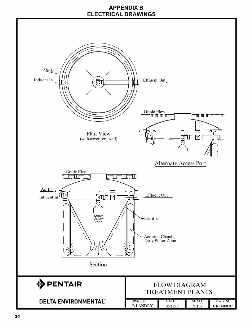
The Ultra Clear™ Aerobic Wastewater Treatment System that you have purchased produces high quality water suitable for various disposal methods. It is used to enhance your on-site wastewater disposal system. You can be proud that in purchasing your Ultra Clear System, with a minimum amount of maintenance, you can directly contribute to a cleaner, safer environment. All wastewater treatment systems of this type work by using the bacteria that nature has provided. By pumping air into the system, the bacteria grow and thrive in much larger amounts than would occur naturally. The overpopulation of bacteria speeds up the process of breaking down domestic wastewater, making it safe to release into the environment. This entire process takes place within the walls of your specially designed, self-contained Ultra Clear Treatment System. Your Ultra Clear System is made up of an outer mixing chamber and center settling chamber. Raw unsettled domestic wastewater enters directly into the mixing chamber. Mixing is accomplished by air passing from the air pump to the air droplines located around the outer wall of the mixing chamber. The design is such that solids remain in suspension with a general flow pattern up the outer plant wall, then down the outside of the settling chamber when the air pump is on. This flow pattern allows a quiet condition in the settling chamber. The mixed liquid enters the hopper-shaped settling chamber at the bottom and travels upward toward the discharge pipe. The quiet condition allows solids to settle down and re-enter the mixing chamber. The result of this process is a clear, odorless discharge, which meets or exceeds state water quality standards. By following the few simple steps that you find in this manual, your Ultra Clear System will provide you with years of service and the knowledge that you are doing your part to protect our groundwater, lakes, rivers and streams.
Ultra Clear is a registered trademark of Delta Environmental, a Pentair Ltd. Company
6
HOMEOWNER CARE AND SERVICE PROVIDER INSTRUCTIONS
The Ultra Clear™ System has been designed and built to provide long term, reliable and efficient service. Once the unit has been installed (see installation instructions), the unit will operate with a minimum amount of attention. Please reference the system’s data plates that are located on the aerobic tank 24" cover, air pump and the alarm panel in the event that a problem arises or service is required. Call 1-800-219-9183 for your local service provider. The following should be accomplished as checks for system failure: Daily
• Observe the warning device, which comes on when the power to the air pump has been interrupted or when the air supply system has malfunctioned. If the alarm is activated, check for a blown fuse or thrown circuit breaker. Check air pump to be sure it is operating. Once accustomed to the soft humming sound of a properly operating unit, any unusual noise is an indication of malfunction. If an unusual noise is detected or total failure is observed, call an authorized Delta Environmental® dealer/distributor.
Weekly
• Check the treatment plant for offensive odor. If such a condition should develop, call an authorized Delta Environmental dealer/distributor.
Every Three Months • The air filter on the air pump should be cleaned. Rinse with warm water if necessary. (See
installation instructions.) Do not use oil or other solvents.
Every Six Months • Clean air filter on the air pump. • Inspect and make any necessary adjustments to mechanical and electrical components.
o Make sure all components are functioning properly (alarms, switches, air pump, etc.). • Inspect the color and turbidity of the effluent and check for any odor.
o No offensive odors should be present; an earthy odor is typical. • Take a sample from the aeration tank and perform a 30-minute settle ability test described in
the “Solids Removal” section. • Break up any sludge that may have developed in the clarifier so it can return to the aeration
zone. Care should be taken to prevent solids from leaving the unit. • The homeowner must be notified in writing if any improper operation is observed and
can not be corrected at the time of service. • Refer to “Troubleshooting Guide” section in this manual.
Note: To keep maintenance to a minimum and ensure high effluent quality, see the section labeled “The following should NOT be used or discarded into the system”.

7
THE FOLLOWING SHOULD NOT BE USED OR DISCARDED INTO THE SYSTEM
• Greases, fats, oils, pesticides, herbicides or any other toxins. • Garbage disposal should be used sparingly. Discard food waste, grease, etc., in the solid waste
bin. Food waste represents additional matter the Fixed Film Wastewater Treatment System would have to digest, increasing pump-out intervals.
• Paints, household chemicals, automobile fluids and mop water should not be put into
the system. • Nonbiodegradable items such as cigarette butts, disposable diapers, feminine hygiene
products, condoms, hair, coffee grounds, rags, paper towels, bandages, latex, plastic or metallic objects, etc. should not be put into the system.
• Laundry loads must be spread out over the week. Once a week multiple loads or half loads are
not recommended. • Citrus products, oranges, lemons, grapefruit, etc. should not be put into the system.
• Additives for septic systems do more harm than good.
• Hydraulic overload due to excessive water from other sources. • Home brewery waste, strong medicines, antibiotics and antibacterial soaps should be avoided. • Strong disinfectants or bleaches. Laundry products such as: Lysol, Pine-Sol, Tidy Bowl or
discharge from water softeners.
• Recommended detergents are powdered, low-sudsing, low phosphates and biodegradable washing soda ingredients such as Gain, Arm & Hammer, Fresh Start and Dash Bright. Fabric softener dryer sheets are also recommended.
• Recommended cleaning products are Nonchlorine, biodegradable and nontoxic such as Ivory
and Sunlight dish washing liquids, Cascade and Sunlight powdered dishwasher detergents, Comet and Biz powdered cleaners and baking soda.
Systems requiring pump-outs due to the above violations are not covered by the warranty. The Ultra Clear™ System is designed to handle domestic wastewater and nothing else should go into it. For anything other than domestic wastewater, contact Delta Environmental®.
8
WARNINGS
• The proper operation of this or any other home sewage system depends upon proper organic loading and the life of the microorganisms inside the system. Delta Environmental® is not responsible for the in-field operation of a system, other than the mechanical and structural workings of the plant itself. We cannot control the amount of harsh chemicals or other harmful substances that may be discharged into the system by the occupants of a household. We can provide only a comprehensive owner's manual that outlines substances that should be kept out of the system.
• Hydraulic overloading (flows in excess of design flow) may cause the sewage treatment system
not to perform to the fullest capabilities.
• Ants have been shown to be destructive to the air pump. Regular care should be taken to prevent infestation of ants near the system. Damage or destruction by ants is not covered under manufacturer's warranty.
• Your state or local health department may require other pieces of equipment to function
separately or in conjunction with equipment manufactured by Delta Environmental. Delta Environmental is not responsible for the mechanical or electrical safety of equipment it does not manufacture or supply with its aerobic treatment units. Particular care should be used in evaluating the electrical or mechanical safety of equipment manufactured by others. This may include but not be limited to electrical control panels or air pumps.
• If electrical service has not been installed for checking the air distribution system during
installation, and if an extension cord is used to test the air pump, NEVER leave the extension cord plugged in. Remove it after testing is completed.
6. Due to a possible fire hazard, DO NOT plug into service equipment on power pole and DO NOT
use extension cords. All electrical work performed by the installer or others must be in accordance with the National Electrical Code (NEC) and local codes.
7. The operation and maintenance outlined in this manual applies to normal operating conditions.
Extreme conditions such as frigid cold temperature, extreme heat and high altitudes may affect the operation and maintenance of this unit. Consult the factory regarding these extreme conditions.
WARNING Failure to Properly Secure the Top May Result in a Serious
Health or Safety Hazard.
California Proposition 65 WarningThis product contains chemicals known to
the State of California to cause cancer or birth defects or other reproductive harm.

9
SOLIDS REMOVAL The Ultra Clear™ Treatment System is designed to provide years of trouble-free operation. Determination of the need for solids removal can be done through a simple test. A one-quart sample should be pulled from the aeration tank and can be done so through the 4" sample port. Allow the sample to settle in a clear one-quart jar for thirty minutes. If the solids content exceeds 60% of the total volume after settling, the treatment plant should be pumped out. Call your local authorized sewage disposal service to have the tank contents pumped out and disposed of properly.
The method of pumping out should be as follows:
• Remove any floating solids by skimming.
• The air pump must be operating to keep the solids in suspension.
• Pump out two-thirds of the tank volume with the suction pipe opening being placed at the tank bottom.
After the pump-out process is complete, fill the tank with fresh water to normal operating level.
Refer to the Installation Instructions to get the treatment plant back into operation. Should indication of improper operation be observed at any time, contact your local authorized Delta Environmental® dealer/distributor. NOTE: The cost associated with pumping the treatment system is not covered under warranty and is not included in the service policy.

10
SEASONAL USE GUIDELINES OF ULTRA CLEAR™ AEROBIC TREATMENT UNIT
These guidelines are for conditions as outlined below and apply for systems that are not in use for periods of time indicated. Site conditions not covered by the following must be forwarded to Delta Environmental® for recommended guidelines to meet the particular site conditions. 1. System not in use for more than one month and less than three months. Electrical power is left on
and there are no frost conditions.
• Leave air pump on and system running. 2. System not in use more than three months. Electrical power is turned off and there are not
frost conditions.
• While system is operating with the air pump on, remove all material and liquid from tank.
• Refill with clean water. • Turn off air pump.
3. System not in use more than three months. Electrical power is on and there are not
frost conditions.
• Leave air pump on and system running; • OR, while system is operating with the air pump on,
remove all material and liquid from tank. • Refill with clean water. • Turn off air pump.
4. System not in use. Electrical power is turned off and there are frost conditions.
• While system is operating with the air pump on, remove all material and liquid from tank.
• Turn off air pump. • If high groundwater is present, fill with clean water. • If no groundwater is present, leave tank empty.
Under no circumstances should the air pump be turned off for more than a few days without removing tank contents!

11
SAMPLING REQUIREMENTS An Ultra Clear™ Aerobic Treatment Plant properly operated and maintained should provide the following effluent quality of:
Carbonaceous Biochemical Oxygen Demand 5 day average (CBOD5) of less than 25 mg/l (or ppm), Suspended Solids (SS) of less than 30 mg/l (or ppm), Volatile Suspended Solids of less than 30 mg/l (or ppm). pH of 6.0 to 9.0 Dissolved Oxygen 1.5 to 3.0 mg/l (or ppm)
Taking Effluent Samples Samples must be taken in the effluent discharge line, an effluent pump or after the chlorine contact tank. We recommend allowing the effluent to flow through the discharge pipe for a minimum of two minutes before taking the sample. This will allow any solids to be flushed out that might have accumulated in the discharge pipe. Please find attached drawing of the sample port. Sampling should be taken by a local certified testing laboratory or by following their procedures. The following recommended guidelines may be used if local procedures are not available: Carbonaceous Biochemical Oxygen Demand (CBOD)
Samples for CBOD analysis may degrade significantly during storage between collection and analysis, resulting in low CBOD values. Minimize reduction of CBOD by analyzing the sample promptly or by cooling it to near-freezing temperature during storage. However, even at low temperature, keep the holding time to a minimum. Warm the chilled samples to 20oC before analysis; some storage time can be used to accomplish this conveniently.
• Grab Samples: If analysis is begun within two hours of collection, cooling is unnecessary. If analysis is not started within two hours of sample collection, keep sample at or below 4oC from the time of collection. Begin analysis within six hours of collection; when this is not possible because the sampling site is distant from the laboratory, store at or below 4oC and report length and temperature of storage to the lab. Never start analysis more than 24 hours after grab sample collection. When samples are to be used for regulatory purposes, make every effort to deliver samples for analysis within six hours of collection.
Total Suspended Solids (TSS) Use resistant glass or plastic bottles, provided that the material in suspension does not adhere to container walls. Begin analysis as soon as possible because of the impracticality of preserving the sample. Refrigerate sample at 4oC to minimize microbiological decomposition of solids.
12
Phosphorus If phosphorous forms are to be differentiated, filter samples immediately after collection. Preserve by freezing at or below –10oC. Add 40mg HgCl2/L to the samples, especially when they are to be stored for long periods. Do not add either acid or 2CHCl3 as a preservative when phosphorous forms are to be determined. If total phosphorus alone is to be determined, add 1 mL concentration HCl or freeze without any additions. Do not store samples containing low concentrations of phosphorus in plastic bottles unless kept in a frozen state because phosphates may be adsorbed onto the walls of plastic bottles.
Rinse all glass containers with hot diluted HCl, then rinse several times in distilled water. Never use commercial detergents containing phosphate for cleaning glassware used in phosphate analysis. Ammonia Nitrogen Most reliable results are obtained on fresh samples. Destroy residual chlorine immediately after sample collection to prevent its reaction with ammonia. If prompt analysis is impossible, preserve samples with 0.8 mL concentration H2SO4/L sample and store at 4oC. The pH of the acid-preserved samples should be between 1.5 and 2. Some wastewater may require more concentration H2SO4 to achieve this pH. If acid preservation is used, neutralize samples with NaOH or KOH immediately before making the determination.

13
™
14
INTALLATION INSTRUCTIONS ONLY FOR USE BY CERTIFIED,
LICENSED INSTALLER 1. Care must be taken offloading and unpacking components. Care must be taken not to
damage fiberglass with forklift or any other offloading device. Check for any damaged components that may have happened in transportation and notified factory within 24 hours of delivery. Prepare an excavation, having a diameter approximately one foot larger than the tank and a depth that will allow approximately three inches of the inspection port to extend above normal ground level. Backfill with a 6-inch layer of sand or gravel if otherwise unable to provide a smooth, level, compact base. We recommend that the hole be roped off in some fashion to prevent injury to passersby.
2. Using lifting lugs provided, place the plant in the excavation so that the inlet and outlet line up
with the sewer piping. The inlet line should slope down toward the plant and the outlet line should slope down away from the plant. The plant should be level within 1/2 inch edge to edge.
3. Position inlet and outlet lines and make connections as necessary, depending upon the
construction materials. The inlet line should be inserted and glued into the inlet elbow and the discharge line should be inserted and glued into the outlet coupling. Note: Open inspection port and make sure discharge tee assembly is level and centered in clarifier prior to attaching discharge piping. Fill the tank with water until water flows from the discharge before backfilling. Backfill around the treatment plant up to the bottom of the discharge connections.
4. Do not install the air pump(s) in a low lying area where water may accumulate. The air pump
should be installed near the control panel and within 100 ft. of the tank. The air pump can be installed outdoors or in a clean, well ventilated area, such as a tool room, garage, etc. If the linear air pump is to be installed in an additional enclosure, the enclosure must be approved by Delta Environmental® in writing.
5. Mount the control panel in an area such that the alarm can be heard and be readily observed.
A 3-wire grounded GFI circuit is required for safety. Install a disconnect switch near the panel to visually disconnect the control panel from the power source. All electrical work shall be done according to NEC and local code requirements. The control panel must be grounded. Connect the source ground wire to the ground location in the panel.
6. The control panel is rated for indoor and outdoor use and contains a fuse for the air pump. An
electrical malfunction in the air pump or wiring to the air pump will cause the fuse to blow. The control panel also contains a pressure switch and visual and audible alarm. Loss of air pressure caused by air pump system malfunction or a high water level in the treatment plant will cause the alarm to sound and light to illuminate.
7. Attach control panel to suitable mounting surface using all four mounting holes on back of box.
Use proper screws of sufficient length to ensure a secure and permanent mounting. 8. Control panel is rated for outdoor service; however, do not place it where it can be immersed in
rising water or where run-off water, such as from a roof, will fall on it. Do not mount it where it is subject to wetting from sprinklers, hoses, etc.

15
9. The control panel must never be connected to a circuit that is not properly grounded. Never
connect the unit to a nongrounded circuit. If there is doubt, have a qualified electrician check for proper grounding. The control panel must be connected to a 20 amp maximum electric source equipped with a ground fault interrupter (GFI) circuit breaker. A standard circuit breaker can be replaced with a GFI circuit breaker, which can be obtained from almost any store that sells electrical supplies.
10. After the control panel is properly mounted, connect conduit and install wiring as shown on
drawings bound herein.
11. Install the float switch wire from the control panel to the treatment plant. Wire can be direct burial type UF 600 volt or can be installed in schedule 40 pvc conduit. Use type THWN, 600 volt if installed in conduit. Wire must be buried in accordance with NEC table 300-5. If in doubt, bury 24" deep. Keep sufficient distance or depth from air line to avoid confusion of pipes or damage to wiring during installation or repair of air piping. Connect to the float switch normally open contacts using underground rated compound filled wire nuts.
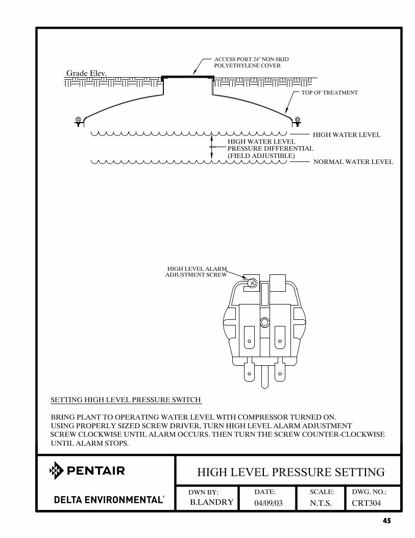
12. If using the CP22 panel, ignore #11. To set the high level pressure switch that detects high water level in the unit, follow the instructions below:
Bring plant to operating water level with compressor turned on. Using properly sized screwdriver, turn high-level alarm adjustment screw clockwise until alarm occurs. Then turn the screw counterclockwise until alarm stops. (See “high level pressure setting” drawing in this manual.)
13. Connect the pressure air tubing to the 1/8" barb-fitting directly to the 3/4" airline or directly to the compressor. Refer to illustrations in Appendix B for appropriate air tubing connections.
14. Install 3/4" schedule 40 PVC piping between air pump and treatment unit. A minimum of 12" ground cover is recommended.
15. Turn power on to control panel. Air pump should start.
16. Check air piping joints for leakage using a soapy water solution. Repair if necessary and then carefully backfill air line and inlet and discharge piping and cover plant to grade level.
17. Recheck water level in the tank.
18. Plant is ready to receive incoming sewage. No special start-up procedures are required. The process is naturally occurring and does not require any special additives.
19. Test alarm circuit by momentarily squeezing air tubing and allowing air pressure to decrease. This should take a few minutes. Alarm should occur. Release air tubing and alarm should stop. Lift float in tank to horizontal position. Alarm should occur. Release float. Alarm should stop. The audible alarm can be turned off by flipping the toggle switch on the panel front door to the left.
20. Close cover on control panel and lock if necessary.

16
21. In the event that a fuse blows, replace with time delay or slow blow, 125 volt minimum
voltage rating and the same amp rating as the existing fuse.
22. The distribution of air to all droplines must be uniform. If the airflow is not evenly distributed, check the air pump or the main air line.
23. Spend time with your customer whenever possible. Review operation instructions. Be sure that the customer has a manual to keep. This saves valuable time avoiding return visits.
24. Retain these instructions for future reference.
25. WARNING: Control panel contains high voltage and must be installed and serviced only by qualified personnel.
26. WARNING: UC series fiberglass construction is furnished with a 24" polyethylene cover with gasket that is securely fastened to the tank lid. The cover must be placed six inches above grade to prevent surface runoff.
27. WARNING: UC series concrete construction is furnished with a 20" Poly-Lok® riser and a cover. Risers are cast into the concrete lid to ensure water tightness. The covers have gaskets and are designed for self-sealing. The cover must be placed six inches above grade to prevent surface runoff.

17
®

18

19

20
®

21
The Basic Four Troubleshooting Guidelines for
Treatment Unit
Is the air pump operating? Is the air filter clean?
1. Visually inspect unit to ensure proper mechanical operation.
Visually examine inspection ports to determine if unit is receiving enough air. Is unit properly ventilated?
Is more water being used by the household than unit’s design?
2. Is system being overloaded hydraulically from the household or an outside source?
Is runoff or groundwater entering the unit, pretreatment tank, dosing tank, piping?
Are there more people using the system than designed for?
3. Is system being biologically overloaded?
Are there more households on unit than designed for?
Talk with homeowner about the correct household products to use.
4. Is a toxic substance being introduced to the unit?
Talk to homeowner about garbage disposal and what waste gets dumped into sinks and drains.
Call manufacturer for further
assistance.
22
TROUBLE SHOOTING GUIDE FOR DELTA ENVIRONMENTAL® ULTRA CLEAR™
AEROBIC TREATMENT UNITS AIR SUPPLY MALFUNCTION 1. Check to be sure all airdrops are working properly. They should be bubbling evenly and forcefully.
A septic (rotten egg) odor could mean that the system is not getting enough air. If the air system is not working, partially working or working very little (slight bubbles), check the following:
a. Check to be sure the air pump is working.
• check timer if one is used • bypass timer temporarily; connect directly to source • check the electrical source • if electrical source is OK – check service guide for pump unit
troubleshooting information • wash air filter on pump • consult manufacturer for servicing information
b. Check to be sure tank is not severely out of level. Air follows a path of least
resistance. The pressure differences at the bottom of drop lines can be enough to prevent or restrict air flow.
c. Check for broken or cracked air lines both outside and inside the tank.
d. Ants will destroy an air pump. Check to see if there is an ant nest around
the air pump.
e. Air pump should be protected from rising water.
f. Always check to see if inlet and outlet lines are correctly installed. INTERNAL ASSEMBLY MALFUNCTION 1. Raw, untreated sewage from the aeration chamber (bubble zone) should not enter the clarifier
(quiet zone) because of improperly installed, loose seals or gaskets where pipe goes through the clarifier wall. Check the size of holes to be sure that there is no clearance for matter to pass through the wall around the piping.
2. Check to be sure all internal piping and connections are tight. DESIGN OVERLOAD 1. The system could be hydraulically overloaded (there is too much water going through the system
for the size of the system). 2. The system could be biologically overloaded (there is too much waste for the size of
the system).

23
IMPROPER INSTALLATION OR SETTLING 1. You should follow the manufacturer’s installation procedures very carefully. 2. Where settling is common, approximately 2" of sand should be placed and tamped in the bottom of
the hole. 3. Proper installation is the first step in preventing callbacks for service problems. 4. Whenever possible, it is important to spend time with the homeowners. Be sure they have an
operations and maintenance manual. A few minutes invested in the beginning will avoid service calls later.
NO HARSH CHEMICALS SHOULD BE PUT INTO THE SYSTEM 1. Water in the aeration chamber (bubble zone) should be the color of chocolate milk. Blue or
gray/blue water indicates heavy use of detergents or other chemicals. If water appears sudsy, there is too much detergent being used.
2. Water in the clarifier (quiet zone) should be clear, but scum and debris may appear on the surface.
Water is discharged into the discharge tee at a minimum of 6–8 inches below water surface. You MAY not be able to see clear water by looking into the tank. Samples must be taken at the sample port.
3. Oils and grease should be kept to a minimum. Grease tends to form in white balls. TROUBLESHOOTING ELECTRICAL SYSTEM 1. Air pump does not run:
a. Check main service for power. b. Check and/or reset GFI receptacle or breaker.
2. Alarm does not occur when air pump is off:
a. Malfunctioning pressure switch – replace. b. Malfunctioning light or buzzer – replace.
3. Alarm occurs continuously even when air pump is running:
a. Air leak in main air system or air tubing to pressure switch – repair leak or replace air line. b. Malfunctioning pressure switch – replace. c. High water level in tank – inspect for cause. d. Short in float switch wire or float switch – repair or replace.
NOTE: All replacement parts are available from your local dealer. CAUTION: Electrical shock or hazard may occur if unit is not serviced properly. The
manufacturer recommends that a licensed electrician be called when electrical problems occur.

24
COMPONENT REPLACEMENT PROCEDURE
• Air Pump: Follow the same procedure as outlined in the “Installation Instructions”.
• Float Switch: Remove Aerobic Treatment Plant’s Riser or 24" cover. Locate float switch cable. Untie knot. Cut float switch cable. Slip float switch cable through rubber grommet into the plant. Replace with exact replacement float switch. Reinstall by reversing the procedure. Reconnect float switch wires using underground rated compound filled wire nuts. See Float Switch Mounting Details.
• Pressure Switch: Turn all power off to the control panel. Remove back plate. Remove screws
securing pressure switch as well as connectors and tubing. Reverse procedure to install new pressure switch.
• Buzzer: Turn all power off to the control panel. Remove screw attaching buzzer to back plate
as well as connectors. Reverse procedure to install new buzzer.
• Lamp Holder: Turn all power off to control power. Remove lock nut securing lamp holder to door as well as connectors. Remove lamp holder. Install new lamp holder with gaskets furnished. Continue with reverse procedure.
• Lamp: Turn all power off to control panel. Remove red lamp cover from front of control panel.
Remove and replace lamp, which is a push-in type. Replace lamp cover and cover gasket.
• Fuse: Turn all power off to control panel. Pull top of fuse holder outward. Remove and replace fuse. Push fuse back into place.
• Buzzer Switch: Turn all power off to control panel. Remove rubber boot on switch. Remove
hex nut from switch on panel front as well as connectors on switch. Reverse procedure to install new switch.

25
GENERAL COMMENTS
• Only factory approved equipment can be used for replacement on individual treatment systems.
• If the decision is made to pump out a system, be sure to contact a licensed waste-hauler.
• If a chronic problem develops and all items have been checked, consult with the factory.
• A properly operating unit will produce a clear, odorless discharge; the mixed liquor in
the aeration tank should be a medium brown color with good settling features and have an earthy smell.
• Keep good records.
Note: If the entire cover needs to be removed on any one of the various model treatment plants, the existing silicone or strip seal must be removed and replaced with a new one. This will provide a positive seal, which will not allow any infiltration into or out of the treatment plant.

26
APPENDIX A SPECIFICATIONS, DIMENSIONS AND
TREATMENT PLANT DRAWINGS

27

28
29

30
SPECIFICATIONS
TREATMENTPLANT
TREATMENTCAPACITY
(GPD)
TOTALVOLUME
(GAL)
AERATIONVOLUME
(GAL)
CLARIFIERVOLUME
(GAL)
BODLOADING(LBS/DAY)
NO. OF AIR
DROPS
UC50 500 764 596 168 1.25 3
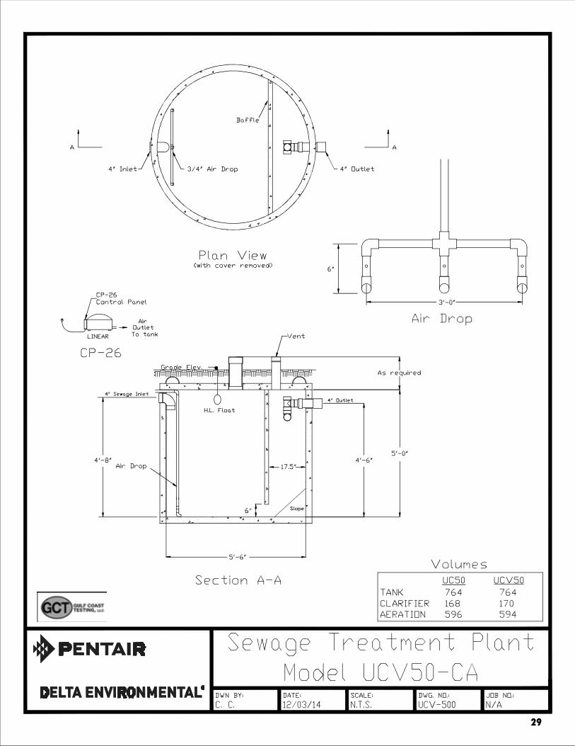
UCV50 500 764 594 170 1.25 3
UC50A 500 909 720 189 1.25 3
UC60A 600 951 750 201 1.5 3
UC60 600 1147 867 280 1.5 3
UC75 750 1438 1100 338 1.88 3
UC75A 750 1174 924 250 1.875 3
UC90 900 1428 1050 378 2.25 3
UC100A 1000 1926 1429 497 2.5 3
UC120 1200 2013 1493 520 3.0 3
UC150 1500 2882 2227 655 3.75 8
UC150A 1500 2358 1838 520 3.25 3
MATERIALS OF CONSTRUCTION Suffix M - Aeration Tank Steel
Cover Steel Clarifier Fiberglass
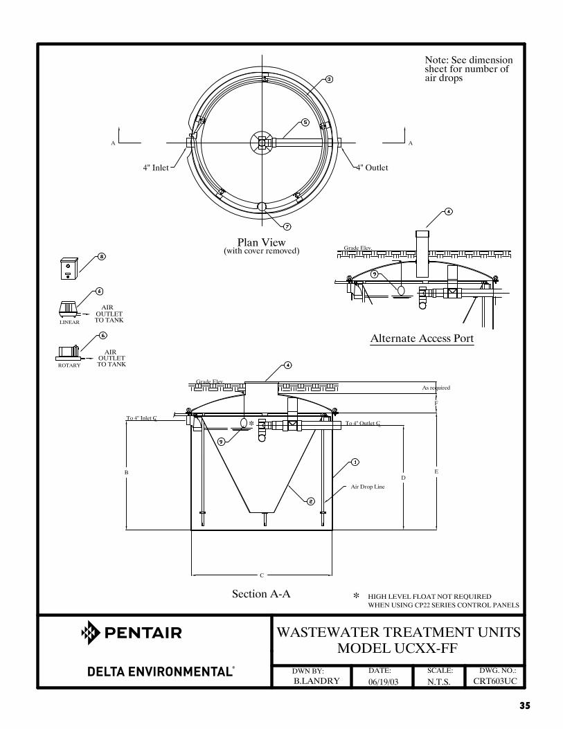
Suffix FF* - Aeration Tank Fiberglass Cover Fiberglass Clarifier Fiberglass
Suffix CA* - Aeration Tank Concrete Cover Concrete Clarifier Fiberglass
*Standard Production Units. Other configurations are available upon special request.
PARTS LIST: ITEM MATERIALS OF CONSTRUCTION Aeration Tank . . . . . . . . . . . . 1. . . . . . See Above Clarifier . . . . . . . . . . . . . . . . . 2. . . . . . See Above Air Distribution System . . . . . 3. . . . . . PVC Access Cover . . . . . . . . . . . . 4. . . . . . Polyethylene Discharge Piping Assembly. . 5. . . . . . PVC Air Pump Assembly . . . . . . . 6. . . . . . See Air Pump Parts List Sample Port . . . . . . . . . . . . . 7. . . . . . PVC Control Panel . . . . . . . . . . . . 8. . . . . . NEMA 3R Steel or NEMA 4X Fiberglass High Water Float Switch . . . . 9. . . . . . Polyethylene

31
Electrical Requirements
Model Compressor Motor fullload Amps
MeasuredOperating
Watts
Electrical Requirements
UC-50 5060A / D60 5078S / D80 HP60 / DM 60 HP80 / DM 80 HP60AAP-60AP-80AP-60-APAP-80-AP
1.752.11.752.11.751.752.11.752.1
63/85 watts 115 volt - single phase
UC-V50 5060A / D60 5078S / D80 HP60 / DM 60 HP80 / DM80 HP60AAP-60AP-80AP-60-APAP-80-AP
1.752.11.752.11.751.752.11.752.1
63/85 watts 115 volt - single phase
UC-50A 5060A / D60 5078S / D80 HP60 / DM 60 HP80 / DM80 HP60AAP-60AP-80AP-60-APAP-80-AP
1.752.11.752.11.751.752.11.752.1
63/85 watts 115 volt - single phase
UC-60A 5078S / D80 HP80 / DM 80 AP-80AP-80-AP5100 / D100
2.12.12.12.12.71
85 watts
110 watts
115 volt - single phase

32
UC-60 5078S / D100 HP80 / DM 80 AP-80AP-80-AP
2.12.12.12.1
85 watts 115 volt - single phase
UC-75 5100SHP100 / DM 100 HP120 / DM 120
2.71 110 watts 115 volt - single phase
UC-75A 5100SHP100 / DM 100
2.71 110 watts 115 volt - single phase
UC-90 5120S / D120 HP120 / DM120 QR-00800823AT05
2.8
10.410.4
157 watts
640 watts 640 watts
115 volt - single phase
UC-100A (2) 5078S / (2) D80 (2) HP80 / (2) DM 80 (1) QR-0080 (1) 0823 (1) AT05
(2) 2.1 (2) 2.1 (1) 10.4 (1) 10.4
(2) 85 watts (2) 85 watts (1) 640 watts (1) 640 watts
115 volt - single phase
UC-120 (2) 5100S / (2) D100 (2) HP100 / (2) DM 100 (1) QR-0080 (1) 0823 (1) AT05
(2) 2.71 (2) 2.71 (1) 10.4 (1) 10.4
(2) 107 watts (2) 107 watts (1) 640 watts (1) 640 watts
115 volt - single phase
UC-150 (3) 5100S / (3) D100 (3) HP100 / (3) DM 100 (2) 5120 / (2) D120 (2) HP120 / (2) DM120 (1) QR-0100 (1) 0823
(3) 2.71 (3) 2.71 (2) 2.71 (2) 2.71 (1) 10.4 (1) 10.4
(3) 110 watts (3) 110 watts (2) 107 watts (2) 107 watts (1) 850 watts(1) 640 watts
115 volt - single phase
UC-150A (2) 5100S / (2) D100 (2) HP100 / (2) DM 100 (1) QR-0080 (1) 0823
(2) 2.1 (2) 2.71 (1)10.4(1)10.4
(2) 157 watts (2) 110 watts (1) 640 watts(1) 640 watts
115 volt - single phase
33
DIMENSIONS
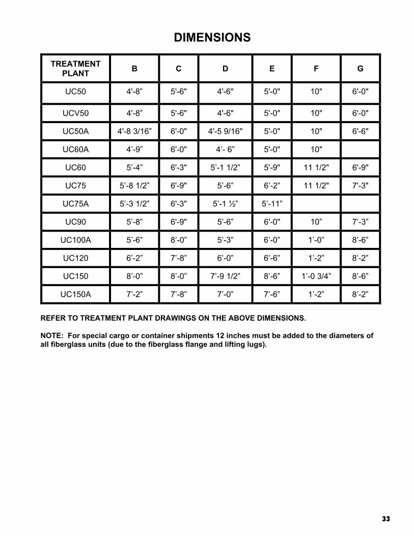
TREATMENTPLANT B C D E F G
UC50 4'-8” 5'-6" 4'-6" 5'-0" 10" 6'-0"
UCV50 4'-8” 5'-6" 4'-6" 5'-0" 10" 6'-0"
UC50A 4'-8 3/16” 6'-0" 4'-5 9/16" 5'-0" 10" 6'-6"
UC60A 4’-9” 6'-0" 4’- 6” 5'-0" 10"
UC60 5’-4” 6'-3" 5’-1 1/2” 5'-9" 11 1/2" 6'-9"
UC75 5’-8 1/2” 6'-9" 5’-6” 6’-2” 11 1/2" 7'-3"
UC75A 5’-3 1/2” 6'-3" 5’-1 ½” 5’-11”
UC90 5’-8” 6'-9" 5’-6” 6'-0" 10” 7’-3”
UC100A 5’-6” 8’-0” 5’-3” 6’-0” 1’-0” 8’-6”
UC120 6’-2” 7’-8” 6’-0” 6’-6” 1’-2” 8’-2”
UC150 8’-0” 8’-0” 7’-9 1/2” 8’-6” 1’-0 3/4” 8’-6”
UC150A 7’-2” 7’-8” 7’-0” 7’-6” 1’-2” 8’-2”
REFER TO TREATMENT PLANT DRAWINGS ON THE ABOVE DIMENSIONS.
NOTE: For special cargo or container shipments 12 inches must be added to the diameters of all fiberglass units (due to the fiberglass flange and lifting lugs).
34
APPENDIX B ELECTRICAL DRAWINGS
35

36

37

38

39

40

41

42

43

44
45

46
47
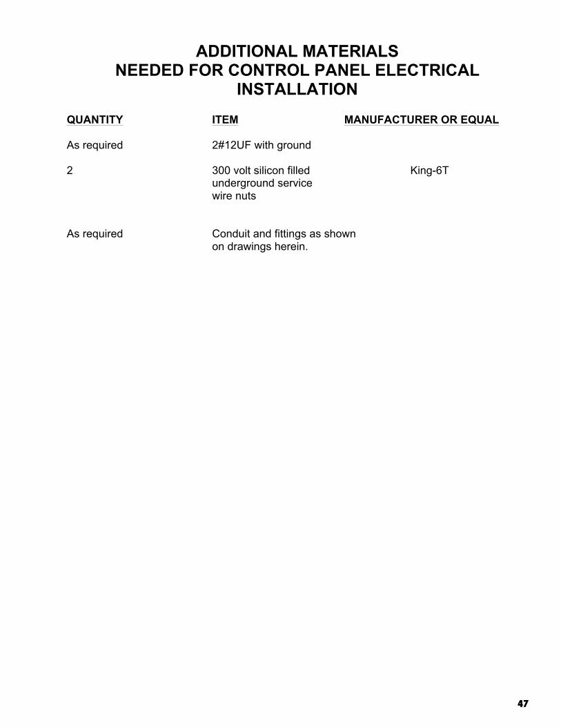
ADDITIONAL MATERIALS NEEDED FOR CONTROL PANEL ELECTRICAL
INSTALLATION QUANTITY ITEM MANUFACTURER OR EQUAL As required 2#12UF with ground 2 300 volt silicon filled King-6T
underground service wire nuts
As required Conduit and fittings as shown on drawings herein.

48
APPENDIX C AIR PUMP DRAWINGS AND PARTS LIST

49
DRAWINGS
5006, 5015, 5020 and V models
5030-A, 5040-A, 5060-A and V models5078S, 5100S-C, 5120S, 5150S, 5200S

50
PARTS LIST
Part Number Description ModelC50141 Shuttle assembly 5006, 5015, 5020 (Plus MO, SE and V models)C50279 Service kit (2 required) 5006, 5015, 5020 (Plus MO, SE and V models)C50144 L-tube (2 required) 5006, 5015, 5020 and V modelsC50283 Gasket, tank 5006, 5015, 5020 and V modelsC50151 Shuttle assembly 5030-A, 5040-A and V modelsC50401-P Service kit 5030-A, 5040-A and V modelsC50554 L-tube (2 required) 5030-A, 5040-A, 5060-A and V modelsC56008 Gasket, tank 5030-A, 5040-A, 5060-A and V modelsC56300 Air filter 5030-A, 5040-A, 5060-A and V modelsC50159 Shuttle assembly 5060-A and V modelsC50397-P Service kit 5060-A and V modelsC50272 Shuttle assembly 5078SC50284 Gasket, tank 5078S, 5100S-C, 5120SC50318 Air filter 5078S, 5100S-C, 5120SC53900 L-tube (2 required) 5078S, 5100S-C, 5120SC56002 Gasket, filter cover 5078S, 5100S-C, 5120SC50402-P Service kit 5078S, 5100S-C, 5120SC51600 Shuttle assembly 5100S-C, 5120SC50265 Shuttle assembly 5150S, 5200SC50285 Gasket, tank 5150S, 5200SC53903 L-tube (2 required) 5150S, 5200SC56005 Gasket, filter cover 5150S, 5200SC56302 Air filter 5150S, 5200SC50403-P Service kit 5150S, 5200S
Note: Service kits (except C50279) include base gasket, filter cover gasket (where appropriate), L-tubes (2), head and diaphragm assembly (2) and intake filter. Service kit C50279 includes head and diaphragm assembly (2) only.

51
PARTS LISTQR-0030QR-0050QR-0080QR-0100
REF.NO. DESCRIPTION
PARTQTY.
291305QR-0030
291306QR-0050
291303QR-0080
291304QR-0100
1 SILENCER 1 C60362 C60363-P
2 VANE KIT[(4) VANES, GASKET] 1 L32100-P L32103-P
3 ENDPLATE 1 L07163 L07166
4 SOUND CHAMBER 1 L07164 L07165
5 GASKET 1 L31058 L31059
6 SHROUD 1 L38230 L38231
7 FILTER KIT[(8) FELTS, (2) O-RINGS] 1 L84194-P L84195-P
8 MOTOR 1 L36236 L36235
– SHIM .0010 THICK A/R* L10556 L10569 (.0010)
– SHIM .0015 THICK A/R* L10557 L10570 (.0015)
– SHIM .0020 THICK A/R* L10558 L10571 (.0020)
*AS REQUIRED

52
EX
PLO
DE
D V
IEW
SC
R -
SO
H/S
S5/
16–1
8 X
3/8
" LG
.
SC
R -
SO
H/S
S1/
4–20
X 1
/4"
LG.
SC
R -
SO
H1/
4–20
X 1
1/2
" LG
.
SC
R -
SO
H1/
4–20
X 2
1/4
" LG
.
QR
-003
0
QR
-008
0
QR
-005
0
QR
-010
0
7
1
3
6
2
8
5
4
53
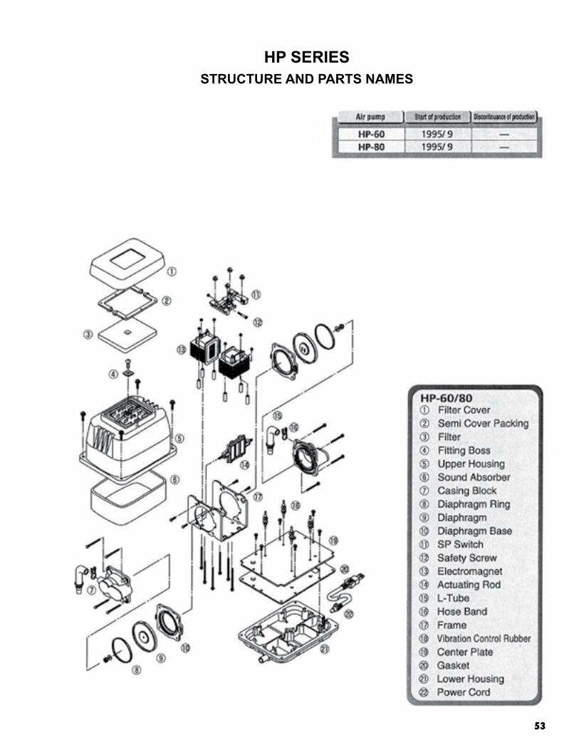
HP SERIESSTRUCTURE AND PARTS NAMES

54
HP SERIESSTRUCTURE AND PARTS NAMES

55

56

57
AP SERIESSTRUCTURE AND PARTS NAMES

58
APPENDIX D NAMEPLATES

59
4”
UC SeriesDelta Environmental™
8263 Florida Blvd. Denham Springs, LA 70726
Phone: 1-800-219-9183 Model UC XXX-X NSF/ANSI STD 40 XXX GPD Class I
Serial No. XX-XXXXX XX
2”
4”
ALARM MALFUNCTION ELECTRICAL PANEL UC Series
Delta Environmental™ 8263 Florida Blvd.
Denham Springs, LA 70726Phone: 1-800-219-9183
Model UC XXX-X NSF/ANSI STD 40 XXX GPD Class I
Serial No. XX-XXXXX XX
3”

60

61
APPENDIX E SERVICE POLICY, WARRANTIES

62
DELTA ENVIRONMENTAL® INDIVIDUAL MECHANICAL WASTEWATER TREATMENT SYSTEM SERVICE POLICY
INITIAL POLICY A two-year initial service policy shall be furnished to the user by the manufacturer or the distributor through the dealer. This policy is to be included in the purchase price from the seller of the system and shall provide the following:
1. An inspection/service call every six months, which includes inspection, adjustment and servicing of the mechanical and electrical component parts as necessary to ensure proper function.
2. An effluent quality inspection every six months consisting of a visual check for color, turbidity,
scum overflow and an examination for odors.
3. If any improper operation is observed that cannot be corrected at that time, the user shall be notified immediately in writing of the conditions and the estimated date of correction. THIS POLICY DOES NOT INCLUDE PUMPING SLUDGE FROM UNIT IF DEEMED NECESSARY.
CONTINUING SERVICE POLICY An annually renewable service policy affording the same coverage as the initial service policy is available. Consult your dealer for pricing information. PARTS Replacement parts or components may be obtained from your local distributor or contact Delta Environmental for information. COMPLAINTS In order for Delta Environmental to properly address complaints, we require that you put in writing the date and nature of the complaint as detailed as possible. This must include the serial number of your system. Send to: Delta Environmental
8263 Florida Blvd. Denham Springs, LA 70726

63
THIS PAGE INTENTIONALLY LEFT BLANK.
LIMITED WARRANTY
Delta Environmental® warrants the parts in each treatment system as follows: linear air pump: limited pro-rated five (5) years – first two (2) years 100%, third (3) year 75%, fourth (4) year 50%, fifth (5) year, 25%. The 3, 4, and 5 year pro-rated portion of this warranty is valid only with a continuing Service Policy in effect. Proof of this continuing Service Policy must be provided. Rotary compressor – limited two (2) years, fiberglass tanks: limited two (2) years, and concrete tanks: limited two (2) years. All warranty questions shall be resolved through Delta Environmental. The warranty on the treatment device is that the device is free from defects in material and workmanship from the date of installation treating household wastewater. Some states do not allow limitations on how long an implied warranty lasts, so the above limitation may not apply. Sole obligation under this warranty is as follows: Delta Environmental shall fulfill this warranty by repairing or exchanging any component part, F.O.B. factory that in Delta Environmental judgment shows evidence of defects, provided said component part has been paid for and is returned through an authorized dealer, transportation prepaid. The warrantee must also specify the nature of the defect to the manufacturer.
The warranty does not cover treatment processes/devices that have been flooded, by external means, or that
have been disassembled by unauthorized persons, improperly installed, subjected to external damage or damaged due to altered or improper wiring or overload protection.
This warranty applies only to the treatment process/device and does not include any of the house wiring,
plumbing, drainage, or disposal system. Delta Environmental is not responsible for any delay or damages caused by defective components or material, or for loss incurred because of interruption of service, or for any other special or consequential damages or incidental expenses arising from the manufacture, sale or use of this process/device.
Delta Environmental reserves the right to revise, change or modify the construction and design of the
treatment process/device for household wastewater or any component part or parts thereof without incurring any obligation to make such changes or modifications in previously sold equipment. Delta Environmental also reserves the right, in making replacements of component parts under this warranty, to furnish a component part which, in its judgment is equivalent to the part replaced.
Under no circumstances will Delta Environmental be responsible to the warrantee for any other direct or
consequential damages, including but not limited to lost profits, lost income, labor charges, delays in production, and/or idle production, which damages are caused by a defect in material and/or workmanship in its parts. Some states do not allow the exclusion of limitation of incidental or consequential damages, so the above limitation or exclusion may not apply to you.
This warranty is expressly in lieu of any other express or implied warranty, excluding any warranty of merchantability or fitness and of any other obligation on the part of Delta Environmental.
This warranty gives you specific legal rights, and you may also have other rights which vary from state to state. Rev. 5/2012
Delta Environmental 8263 Florida Blvd. Denham Springs, LA 70726 1-800-219-9183
DELTA ENVIRONMENTAL