Embed Size (px)
Citation preview

1
3.60 (91.4)(96.5)3.80
1.95(49.5)
(2.5).10
(104.1)4.10
(44.5)1.75
PAR91 32 4 5 6 7 8 10 1311 12 14 15
SEL RST
PS 1 PS 2�����������
AB
GENERAL DESCRIPTIONThe PAXLCR is a versatile meter that provides a single or dual counter with
rate indication, scaling and dual relay outputs. The 6-digit display has 0.56" high digits with adjustable display intensity. The display can be toggled manually or automatically between the selected counter and rate values.
The meter has two signal inputs and a choice of eight different count modes. These include bi-directional, quadrature and anti-coincidence counting, as well as a dual counter mode. When programmed as a Dual Counter, each counter has separate scaling and decimal point selection.
Rate indication is available in all count modes. The Rate Indicator has separate scaling and decimal point selection, along with programmable display update times. In addition to the signal inputs, the User Input can be programmed to perform a variety of meter control functions.
Two setpoint outputs are provided, each with a Form C relay. The outputs can activate based on either counter or rate setpoint values. An internal batch counter can be used to count setpoint output activations.
The PAXLCR can be powered from a wide range of AC or DC voltages. The meter has been specifically designed for harsh industrial environments. With a NEMA 4X/IP65 sealed bezel and extensive testing to meet CE requirements, the meter provides a tough yet reliable application solution.
MODEL NO. DESCRIPTION PART NUMBER
PAXLCR Dual Counter & Rate Meter with Dual Relay Output PAXLCR00
PAXLCRU UL Listed Dual Counter & Rate Meter with Dual Relay Output PAXLCRU0
SAFETY SUMMARYAll safety regulations, local codes and instructions that appear in this and
corresponding literature, or on equipment, must be observed to ensure personal safety and to prevent damage to either the instrument or equipment connected to it. If equipment is used in a manner not specified by the manufacturer, the protection provided by the equipment may be impaired. Do not use this meter to directly command motors, valves, or other actuators not equipped with safeguards. To do so can be potentially harmful to persons or equipment in the event of a fault to the meter
SPECIFICATIONS1. DISPLAY: 6 digit, 0.56" (14.2 mm) intensity adjustable Red LED2. POWER REQUIREMENTS:
AC POWER: 50 to 250 VAC 50/60 Hz, 12 VAIsolation: 2300 Vrms for 1 min. to all inputs and outputsDC POWER: 21.6 to 250 VDC, 6 WDC Out: +24 VDC @ 100 mA if input voltage is greater than 50 VAC/VDC
+24 VDC @ 50 mA if input voltage is less than 50 VDC3. COUNTER DISPLAYS:
Counter A: 6-digits, enabled in all count modesDisplay Designator: “A” to the left side of the displayDisplay Range: -99999 to 999999
Counter B: 6-digits, enabled in Dual Count mode or Batch CounterDisplay Designator: “B” to the left side of the displayDisplay Range: 0 to 999999 (positive count only)
Overflow Indication: Display “” alternates with overflowed count valueMaximum Count Rates: 50% duty cycle, count mode dependent.
With setpoints disabled: 25 KHz, all modes except Quadrature x4 (23 KHz).With setpoint(s) enabled: 20 KHz, all modes except Dual Counter (14 KHz),
Quadrature x2 (13 KHz) and Quadrature x4 (12 KHz).
6 DIGIT, 0.56" HIGH RED LED DISPLAY
PROGRAMMABLE SCALING FOR COUNT AND RATE
BI-DIRECTIONAL COUNTING, UP/DOWN CONTROL
QUADRATURE SENSING (UP TO 4 TIMES RESOLUTION)
BUILT-IN BATCH COUNTING CAPABILITY
PROGRAMMABLE USER INPUT
DUAL 5 AMP FORM C RELAYS
UNIVERSALLY POWERED
NEMA 4X/IP65 SEALED FRONT BEZEL
MODEL PAXLCR - PAX LITE DUAL COUNTER AND RATE METER
DIMENSIONS In inches (mm)
Bulletin No. PAXLCR- B
Drawing No. LP0749
Released 04/09
Tel +1 (717) 767-6511
Fax +1 (717) 764-0839
www.redlion.net
CAUTION: Risk of Danger.Read complete instructions prior to
installation and operation of the unit.
CAUTION: Risk of electric shock.
ORDERING INFORMATION
Note: Recommended minimum clearance (behind the panel) for mounting clip installation is 2.1" (53.4) H x 5.0" (127) W.
CC US LISTEDUS LISTEDULR
IND. CONT. EQ.51EB
For Model No. PAXLCRU0 Only

2
4. RATE DISPLAY: 6-digits, may be enabled or disabled in any count modeDisplay Range: 0 to 999999Over Range Display: “”Maximum Frequency: 25 KHzMinimum Frequency: 0.01 HzAccuracy: ±0.01%
5. COUNT/RATE SIGNAL INPUTS (INPUT A and INPUT B):See Section 2.0 Setting the DIP Switches for complete Input specifications. DIP switch selectable inputs accept pulses from a variety of sources. Both inputs allow selectable active low or active high logic, and selectable input filtering for low frequency signals or switch contact debounce.Input A: Logic level or magnetic pickup signals.
Trigger levels: VIL = 1.25 V max; VIH = 2.75 V min; VMAX = 28 VDCMag. pickup sensitivity: 200 mV peak, 100 mV hysteresis, 40 V peak max.
Input B: Logic level signals onlyTrigger levels: VIL = 1.0 V max; VIH = 2.4 V min; VMAX = 28 VDC
6. USER INPUT: ProgrammableSoftware selectable for active logic state: active low, pull-up (24.7 K to +5
VDC) or active high, pull-down resistor (20 K).Trigger levels: VIL = 1.0 V max; VIH = 2.4 V min; VMAX = 28 VDCResponse Time: 10 msec typ.; 50 msec debounce (activation and release)
7. MEMORY: Nonvolatile E2PROM retains all programming parameters and count values when power is removed.
8. OUTPUTS:Type: Dual Form C contactsIsolation to Input & User/Exc Commons: 1400 Vrms for 1 min.
Working Voltage: 150 VrmsContact Rating: 5 amps @ 120/240 VAC or 28 VDC (resistive load), 1/8
H.P. @ 120 VAC (inductive load)Life Expectancy: 100 K cycles min. at full load rating. External RC snubber
extends relay life for operation with inductive loads.Response Time: Turn On or Off: 4 msec max.
9. ENVIRONMENTAL CONDITIONS:Operating temperature: 0 to 50 °CStorage temperature: -40 to 70 °COperating and storage humidity: 0 to 85% max. RH (non-condensing)Vibration According to IEC 68-2-6: Operational 5 to 150 Hz, in X, Y, Z
direction for 1.5 hours, 2g’s.Shock According to IEC 68-2-27: Operational 30 g (10g relay), 11 msec in 3
directions.Altitude: Up to 2,000 meters
10. CONNECTIONS: High compression cage-clamp terminal blockWire Strip Length: 0.3" (7.5 mm)Wire Gage: 30-14 AWG copper wireTorque: 4.5 inch-lbs (0.51 N-m) max.
11. CONSTRUCTION: This unit is rated for NEMA 4X/IP65 outdoor use. IP20 Touch safe. Installation Category II, Pollution Degree 2. One piece bezel/case. Flame resistant. Synthetic rubber keypad. Panel gasket and mounting clip included.
12. CERTIFICATIONS AND COMPLIANCES:SAFETY
Type 4X Enclosure rating (Face only), UL50IEC 61010-1, EN 61010-1: Safety requirements for electrical equipment
for measurement, control, and laboratory use, Part 1.IP65 Enclosure rating (Face only), IEC 529IP20 Enclosure rating (Rear of unit), IEC 529For Model No. PAXLCRU0 Only: UL Listed, File # E137808, UL508,
CSA C22.2 No. 14-M95LISTED by Und. Lab. Inc. to U.S. and Canadian safety standards
ELECTROMAGNETIC COMPATIBILITYEmissions and Immunity to EN 61326: Electrical Equipment for Measurement,
Control and Laboratory use.
Notes: 1. Criterion A: Normal operation within specified limits.2. Criterion C: Temporary loss of function which requires operator intervention.
13. WEIGHT: 10.4 oz. (295 g)
1.0 INSTALLING THE METERInstallation
The PAX Lite meets NEMA 4X/IP65 requirements when properly installed. The unit is intended to be mounted into an enclosed panel. Prepare the panel cutout to the dimensions shown. Remove the panel latch from the unit. Slide the panel gasket over the rear of the unit to the back of the bezel. The unit should be installed fully assembled. Insert the unit into the panel cutout.
While holding the unit in place, push the panel latch over the rear of the unit so that the tabs of the panel latch engage in the slots on the case. The panel latch
should be engaged in the farthest forward slot possible. To achieve a proper seal, tighten the
latch screws evenly until the unit is snug in the panel (Torque to approximately
7 in-lbs [79N-cm]). Do not over-tighten the screws.
Installation EnvironmentThe unit should be installed in a location that does not exceed the maximum
operating temperature and provides good air circulation. Placing the unit near devices that generate excessive heat should be avoided.
The bezel should be cleaned only with a soft cloth and neutral soap product. Do NOT use solvents. Continuous exposure to direct sunlight may accelerate the aging process of the bezel.
Do not use tools of any kind (screwdrivers, pens, pencils, etc.) to operate the keypad of the unit.
-.00-.00
(92 )(92 )-.0-.0+.8+.8
3.623.62 +.03+.03
(45 )(45 )1.771.77
-.0-.0+.5+.5-.00-.00+.02+.02
PANEL CUT-OUT
PANEL GASKET
BEZEL
PANEL MOUNTING SCREWS
LATCHING SLOTS
PANEL
LATCHING TABS
PANEL LATCH
Immunity to Industrial Locations:
Emissions:
Electrostatic discharge EN 61000-4-2 Criterion A4 kV contact discharge8 kV air discharge
Electromagnetic RF fields EN 61000-4-3 Criterion A10 V/m
2 kV L&N-E power
Fast transients (burst) EN 61000-4-4 Criterion A2 kV power1 kV signal
Surge EN 61000-4-5 Criterion C1 kV L-L,
0.5 cycle
RF conducted interference EN 61000-4-6 Criterion A3 V/rms
Voltage dip/interruptions EN 61000-4-11 Criterion A
Emissions EN 55011 Class A

3
3.0 WIRING THE METERWIRING OVERVIEW
Electrical connections are made via screw-clamp terminals located on the back of the meter. All conductors should conform to the meter’s voltage and current ratings. All cabling should conform to appropriate standards of good installation, local codes and regulations. It is recommended that the power supplied to the meter (DC or AC) be protected by a fuse or circuit breaker.
When wiring the meter, compare the numbers embossed on the back of the meter case against those shown in wiring drawings for proper wire position. Strip the wire, leaving approximately 0.3" (7.5 mm) bare lead exposed (stranded wires should be tinned with solder.) Insert the lead under the correct screw-clamp terminal and tighten until the wire is secure. (Pull wire to verify tightness.)
EMC INSTALLATION GUIDELINESAlthough this meter is designed with a high degree of immunity to Electro-
Magnetic Interference (EMI), proper installation and wiring methods must be followed to ensure compatibility in each application. The type of the electrical noise, source or coupling method into the meter may be different for various installations. The meter becomes more immune to EMI with fewer I/O connections. Cable length, routing, and shield termination are very important and can mean the difference between a successful or troublesome installation. Listed below are some EMC guidelines for successful installation in an industrial environment.1. The meter should be properly connected to protective earth.2. Use shielded (screened) cables for all Signal and Control inputs. The shield
(screen) pigtail connection should be made as short as possible. The connection point for the shield depends somewhat upon the application. Listed below are the recommended methods of connecting the shield, in order of their effectiveness.a. Connect the shield only at the panel where the unit is mounted to earth
ground (protective earth).b. Connect the shield to earth ground at both ends of the cable, usually when
the noise source frequency is above 1 MHz.
c. Connect the shield to common of the meter and leave the other end of the shield unconnected and insulated from earth ground.
3. Never run Signal or Control cables in the same conduit or raceway with AC power lines, conductors feeding motors, solenoids, SCR controls, and heaters, etc. The cables should be ran in metal conduit that is properly grounded. This is especially useful in applications where cable runs are long and portable two-way radios are used in close proximity or if the installation is near a commercial radio transmitter.
4. Signal or Control cables within an enclosure should be routed as far as possible from contactors, control relays, transformers, and other noisy components.
5. In extremely high EMI environments, the use of external EMI suppression devices, such as ferrite suppression cores, is effective. Install them on Signal and Control cables as close to the unit as possible. Loop the cable through the core several times or use multiple cores on each cable for additional protection. Install line filters on the power input cable to the unit to suppress power line interference. Install them near the power entry point of the enclosure. The following EMI suppression devices (or equivalent) are recommended:
Ferrite Suppression Cores for signal and control cables:Fair-Rite # 0443167251 (RLC# FCOR0000)TDK # ZCAT3035-1330ASteward # 28B2029-0A0
Line Filters for input power cables:Schaffner # FN610-1/07 (RLC# LFIL0000)Schaffner # FN670-1.8/07Corcom # 1 VR3
Note: Reference manufacturer's instructions when installing a line filter.6. Long cable runs are more susceptible to EMI pickup than short cable runs.
Therefore, keep cable runs as short as possible.7. Switching of inductive loads produces high EMI. Use of snubbers across
inductive loads suppresses EMI.Snubber: RLC# SNUB0000.
2.0 SETTING THE DIP SWITCHESTo access the switches, remove the meter base from the case by firmly
squeezing and pulling back on the side rear finger tabs. This should lower the latch below the case slot (which is located just in front of the finger tabs). It is recommended to release the latch on one side, then start on the other side latch.
Warning: Exposed line voltage exists on the circuit boards.Remove all power to the meter and load circuits before accessing inside of the meter.
SWITCH 1 (Input A)LOGIC: Input A trigger levels VIL = 1.25 V max.; VIH = 2.75 V min.;
VMAX = 28 VDCMAG: 200 mV peak input sensitivity; 100 mV hysteresis; maximum voltage:
40 V peak (28 Vrms); Must also have Input A SRC switch ON. (Not recommended with counting applications.)
SWITCH 2 (Input A) {See Note 1}SNK.: Adds internal 7.8 K pull-up resistor to +5 VDC, IMAX = 0.7 mA.SRC.: Adds internal 3.9 K pull-down resistor, 7.2 mA max. @ 28 VDC max.
SWITCH 3 (Input A)HI Frequency: Removes damping capacitor and allows max. frequency.LO Frequency: Adds a damping capacitor for switch contact bounce. Limits
input frequency to 50 Hz and input pulse widths to 10 msec.
SWITCH 4 (Input B) {See Note 1}SNK.: Adds internal 7.8 K pull-up resistor to +5 VDC, IMAX = 0.7 mA.SRC.: Adds internal 3.9 K pull-down resistor, 7.2 mA max. @ 28 VDC max.
SWITCH 5 (Input B)HI Frequency: Removes damping capacitor and allows max. frequency.LO Frequency: Adds a damping capacitor for switch contact bounce. Limits
input frequency to 50 Hz and input pulse widths to 10 msec.
Note 1: When the DIP switch is in the SNK position (OFF), the signal input is configured as active low. When the switch is in the SRC position (ON), the signal input is configured as active high.
345
ON
SNK.HI FREQ.
HI FREQ.
SRC.LO FREQ.
LO FREQ.
Factory Setting
21
SNK.
LOGIC
SRC.
MAG.Input A
Input B
MainCircuitBoard
REAR TERMINALS
54321
FRONT DISPLAY
INPUT SET-UPDIP SWITCHES

4
3.3 USER INPUT WIRING
CAUTION: DC common (Terminal 4) is NOT isolated from Input common (Terminal 7) or User common (Terminal 9). In order to preserve the safety of the meter application, DC common must be suitably isolated from hazardous live earth referenced voltage; or Input common and User common must be at protective earth ground potential. If not, hazardous voltage may be present at the Signal or User Inputs, and Input or User common terminals. Appropriate considerations must then be given to the potential of the Input or User common with respect to earth ground.
Terminal 8: User InputTerminal 9: User Common
3.4 SETPOINT (OUTPUT) WIRING
Terminal 10: NC 1Terminal 11: NO 1Terminal 12: Relay 1 CommonTerminal 13: NC 2Terminal 14: NO 2Terminal 15: Relay 2 Common
USER INPUT8
USER COMMON9
USER INPUT
USER COMMMON9
8+
-
10 N.C. 1
COMM 112
11 N.O. 1
13
14
15
N.C. 2
N.O. 2
COMM 2
Current Sinking (Active Low Logic)
Current Sourcing (Active High Logic)
3.2 INPUT SIGNAL WIRING
3.1 POWER WIRING
COMMON
+ 24V EXC
4
3DC Out PowerTerminal 3: + 24 VDC OUTTerminal 4: Common
PowerTerminal 1: VAC/DC +Terminal 2: VAC/DC -
1
2
AC/DC
AC/DC
+
-
~~
21
ON
3 4*
MAGNETIC PICKUPINPUT B
COMMON
INPUT A
COMMON
4
5
6
7
*5
+24V EXC. 3
t 2 5 A MAXResistor to Limit Current
ON
1 2 3*
4*
AC
*5
INPUT A
INPUT B
COMMON 7
6
5
+24V EXC.
COMMON
3
4 1 2
ON
3 4* *
2.2 kΩ
*5
INPUT A
INPUT B
COMMON 7
6
5
+24V EXC.
COMMON
3
4
21
ON
3 4* *
O.C.NPN
*5
INPUT A
INPUT B
COMMON 7
6
5
+24V EXC.
COMMON
3
4 1 2 3
ON
*4*
O.C.PNP
*5
INPUT A
INPUT B
COMMON 7
6
5
+24V EXC.
COMMON
3
4 1 2 3 4
ON
*
COMMON
+5 V
*5
INPUT A
INPUT B
COMMON 7
6
5
+24V EXC.
COMMON
3
4
21
ON
* *3 4
*5
INPUT A
INPUT B
COMMON 7
6
5
+24V EXC.
COMMON
3
4*
1 2 3
ON
*4*5
INPUT A
INPUT B
COMMON 7
6
5
+24V EXC.
COMMON
3
4
AC Inputs From Tach Generators, Etc.Input A
Two Wire Proximity, Current SourceInput A
Magnetic PickupInput A
Current Sourcing OutputInput A
Interfacing With TTLInput A
Current Sinking OutputInput A
Switch or Isolated Transistor; Current SinkInput A
1 2 3 4
ON
5
INPUT A
INPUT B
COMMON 7
6
5
+24V EXC.
COMMON
3
4
Switch or Isolated Transistor; Current SourceInput A
* Switch position is application dependent.
Current Sink Output; Quad/Direction
Shaded areas not recommended for counting applications.
The meter provides a choice of eight different count modes using two signal inputs, A and B. The Count Mode selected determines the action of Inputs A and B. Section 5.1, Input Setup Parameters, provides details on count mode selection and input action.
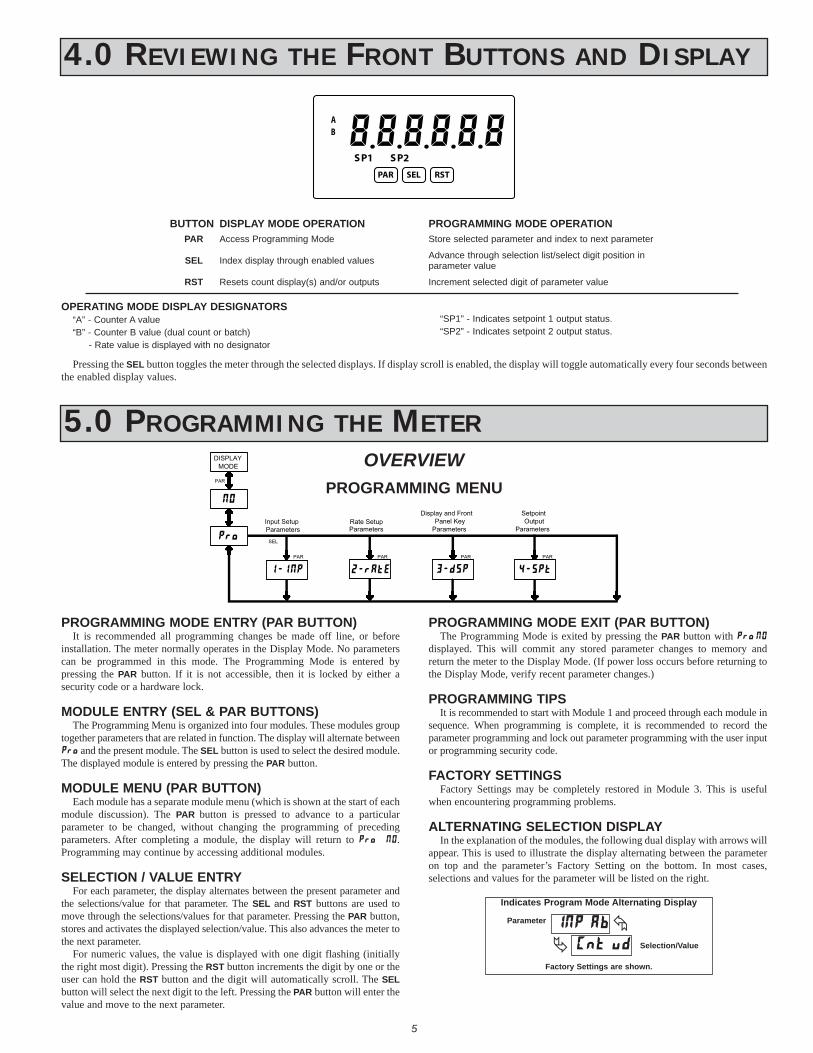
4.0 REVIEWING THE FRONT BUTTONS AND DISPLAY
�����������BA
RSTSELPAR
1SP 2SP
BUTTON DISPLAY MODE OPERATION PROGRAMMING MODE OPERATIONPAR Access Programming Mode Store selected parameter and index to next parameter
RST
SEL
Resets count display(s) and/or outputs
Index display through enabled values
OPERATING MODE DISPLAY DESIGNATORS“A” - Counter A value“B” - Counter B value (dual count or batch) - Rate value is displayed with no designator
“SP1” - Indicates setpoint 1 output status.“SP2” - Indicates setpoint 2 output status.
Pressing the SEL button toggles the meter through the selected displays. If display scroll is enabled, the display will toggle automatically every four seconds between the enabled display values.
Advance through selection list/select digit position in parameter value
Increment selected digit of parameter value
5
PROGRAMMING MODE ENTRY (PAR BUTTON)It is recommended all programming changes be made off line, or before
installation. The meter normally operates in the Display Mode. No parameters can be programmed in this mode. The Programming Mode is entered by pressing the PAR button. If it is not accessible, then it is locked by either a security code or a hardware lock.
MODULE ENTRY (SEL & PAR BUTTONS)The Programming Menu is organized into four modules. These modules group
together parameters that are related in function. The display will alternate between and the present module. The SEL button is used to select the desired module. The displayed module is entered by pressing the PAR button.
MODULE MENU (PAR BUTTON)Each module has a separate module menu (which is shown at the start of each
module discussion). The PAR button is pressed to advance to a particular parameter to be changed, without changing the programming of preceding parameters. After completing a module, the display will return to . Programming may continue by accessing additional modules.
SELECTION / VALUE ENTRYFor each parameter, the display alternates between the present parameter and
the selections/value for that parameter. The SEL and RST buttons are used to move through the selections/values for that parameter. Pressing the PAR button, stores and activates the displayed selection/value. This also advances the meter to the next parameter.
For numeric values, the value is displayed with one digit flashing (initially the right most digit). Pressing the RST button increments the digit by one or the user can hold the RST button and the digit will automatically scroll. The SEL button will select the next digit to the left. Pressing the PAR button will enter the value and move to the next parameter.
PROGRAMMING MODE EXIT (PAR BUTTON)The Programming Mode is exited by pressing the PAR button with
displayed. This will commit any stored parameter changes to memory and return the meter to the Display Mode. (If power loss occurs before returning to the Display Mode, verify recent parameter changes.)
PROGRAMMING TIPSIt is recommended to start with Module 1 and proceed through each module in
sequence. When programming is complete, it is recommended to record the parameter programming and lock out parameter programming with the user input or programming security code.
FACTORY SETTINGSFactory Settings may be completely restored in Module 3. This is useful
when encountering programming problems.
ALTERNATING SELECTION DISPLAYIn the explanation of the modules, the following dual display with arrows will
appear. This is used to illustrate the display alternating between the parameter on top and the parameter’s Factory Setting on the bottom. In most cases, selections and values for the parameter will be listed on the right.
Indicates Program Mode Alternating Display
Factory Settings are shown.
Parameter
Selection/Value
5.0 PROGRAMMING THE METER
ParametersOutput
Setpoint
ParametersInput Setup
���
DISPLAYMODE
Panel KeyParameters
�����
Parameters
Display and Front
PAR
SEL
PAR PAR PAR PAR
���� ����� ����
Rate Setup
OVERVIEWPROGRAMMING MENU

COUNTER A DECIMAL POSITION
This selects the decimal point position for Counter A. The selection will also affect Counter A scale factor calculations.
COUNTER A SCALE FACTOR
The number of input counts is multiplied by the scale factor to obtain the desired process value. A scale factor of 1.0000 will result in the display of the actual number of input counts. (Details on scaling calculations are explained at the end of this section.)*
to COUNTER B DECIMAL POSITION
This selects the decimal point position for Counter B. The selection will also affect Counter B scale factor calculations.
COUNTER A COUNT LOAD VALUE
Counter A resets to this value if Reset to Count Load action is selected. To enter a negative Count Load value, increment digit 6 to display a “-” sign.*
to
PAR
����� �
Dual Count or Batch Only
Counter B Scale Factor
Counter A Reset Action
��� �������� �� ����
Counter A Decimal Point
Count Mode
Counter B Decimal Point
Counter A Scale Factor
Dual Count or Batch Only
Counter B Batch Count
Enable
���� �� ������
�����
Counter A Count Direction
Counter Reset at Power-up
����
User Input Function
User Input Assignment
Counter A Count Load
Value
��������� �����
5.1 MODULE 1 - INPUT SETUP PARAMETERS ()PARAMETER MENU
COUNT MODE
Select the count mode that corresponds with your application. The input actions are shown in the boxes below. For simple counting applications, it is recommended to use Count with Direction for the count mode. Simply leave the direction input unconnected.
Shaded area selections only apply when Counter B is enabled (Dual Count mode or batch counter).
Counter A SubtractCounter A Add
Counter A AddCounter A Add
Quad ACount A
Quad ACount A
Quad ACount A
Counter B AddCounter A Add
Counter A AddRate only
Counter A DirectionCounter A
INPUT B ACTIONINPUT A ACTION
2 Input Add/Subtract
2 Input Add/Add
Quadrature x4
Quadrature x2
Quadrature x1
Dual Counter
Rate/Counter
Count with Direction
DISPLAY MODE
Note: The Rate indicator signal is derived from Input A in all count modes.
6
COUNTER A RESET ACTION
When Counter A is reset, it returns to Zero or Counter A Count Load value. This reset action applies to all Counter A resets, except a Setpoint generated Counter Auto Reset programmed in Module 4.
COUNTER B BATCH COUNT ENABLE
The Counter B Batch Count function internally counts the number of output activations of the selected setpoint(s). The count source for the batch counter can be SP1, SP2 or both. Batch counting is available in all count modes except Dual Counter, which uses an external input signal for Counter B.
COUNTER A COUNT DIRECTION
Reverse () switches the normal Counter A count direction shown in the Count Mode parameter chart.
*For value entry instructions, refer to selection/value entry in the Programming The Meter section.
COUNTER RESET AT POWER-UP
COUNTER B SCALE FACTOR
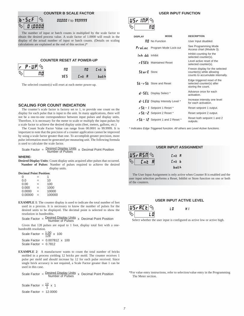
The number of input or batch counts is multiplied by the scale factor to obtain the desired process value. A scale factor of 1.0000 will result in the display of the actual number of input or batch counts. (Details on scaling calculations are explained at the end of this section.)*
to
SCALING FOR COUNT INDICATIONThe counter’s scale factor is factory set to 1, to provide one count on the
display for each pulse that is input to the unit. In many applications, there will not be a one-to-one correspondence between input pulses and display units. Therefore, it is necessary for the meter to scale or multiply the input pulses by a scale factor to achieve the desired display units (feet, meters, gallons, etc.)
The Count Scale Factor Value can range from 00.0001 to 99.9999. It is important to note that the precision of a counter application cannot be improved by using a scale factor greater than one. To accomplish greater precision, more pulse information must be generated per measuring unit. The following formula is used to calculate the scale factor.
Scale Factor = Desired Display Units x Decimal Point Position Number of Pulses
WHERE:Desired Display Units: Count display units acquired after pulses that occurred.
Number of Pulses: Number of pulses required to achieve the desired display units.
Decimal Point Position: 0 = 10.0 = 100.00 = 1000.000 = 10000.0000 = 100000.00000 = 100000
EXAMPLE 1: The counter display is used to indicate the total number of feet used in a process. It is necessary to know the number of pulses for the desired units to be displayed. The decimal point is selected to show the resolution in hundredths.Scale Factor = Desired Display Units x Decimal Point Position Number of PulsesGiven that 128 pulses are equal to 1 foot, display total feet with a one-
hundredth resolution. Scale Factor = 1.00 x 100 128Scale Factor = 0.007812 x 100Scale Factor = 0.7812
EXAMPLE 2: A manufacturer wants to count the total number of bricks molded in a process yielding 12 bricks per mold. The counter receives 1 pulse per mold and should increase by 12 for each pulse received. Since single brick accuracy is not required, a Scale Factor greater than 1 can be used in this case.
Scale Factor = Desired Display Units x Decimal Point Position Number of Pulses
Scale Factor = 12 x 1 1Scale Factor = 12.0000
*For value entry instructions, refer to selection/value entry in the Programming The Meter section.
USER INPUT ASSIGNMENT
The User Input Assignment is only active when Counter B is enabled and the user input selection performs a Reset, Inhibit or Store function on one or both of the counters.
USER INPUT FUNCTION
MODEDISPLAY
No Function
DESCRIPTION
User Input disabled.
Program Mode Lock-out
Maintained Reset
Inhibit
Level active reset of the selected counter(s).
Inhibit counting for the selected counter(s).
Store
Store and Reset
Edge triggered reset of the selected counter(s) after storing the count.
See Programming Mode Access chart (Module 3).
Setpoint 1 and 2 Reset *
Setpoint 2 Reset *
Setpoint 1 Reset *
Display Intensity Level *
Display Select *
Freeze display for the selected counter(s) while allowing counts to accumulate internally.
Reset both setpoint 1 and 2outputs.
Reset setpoint 2 output.
Reset setpoint 1 output.
Increase intensity one level for each activation.
Advance once for each activation.
7
USER INPUT ACTIVE LEVEL
Select whether the user input is configured as active low or active high.
The selected counter(s) will reset at each meter power-up.
* Indicates Edge Triggered function. All others are Level Active functions.

8
The Low Update Time is the minimum amount of time between display updates for the Rate display. Values of 0.1 and 0.2 seconds will update the display correctly but may cause the display to appear unsteady.
RATE LOW UPDATE TIME (DISPLAY UPDATE)
toseconds
The High Update Time is the maximum amount of time before the Rate display is forced to zero. (For more explanation, refer to Input Frequency Calculation.) The High Update Time must be higher than the Low Update Time and higher than the desired slowest readable speed (one divided by pulses per second). The factory setting of 2.0, will force the display to zero for speeds below 0.5 Hz or a pulse every 2 seconds.
RATE HIGH UPDATE TIME (DISPLAY ZERO)
toseconds
5.2 MODULE 2 - RATE SETUP PARAMETERS ()
PAR
��� � �
Rate Scaling Display Value
���� ���
Rate Decimal Point
����
Rate Enable
Rate Input Scaling Style
� ��� �����
Rate High Update Time
Rate Scaling Input Value
���� �����
Rate Low Update Time
PARAMETER MENU
RATE ENABLE
This parameter enables the Rate display. For maximum input frequency, Rate Enable should be set to when not in use. When set to , the remaining rate parameters are not accessible.
This selects the decimal point position for the rate display. This parameter does not affect rate scaling calculations.
RATE DECIMAL POINT
RATE SCALING INPUT VALUE
RATE SCALING DISPLAY VALUE
Enter the desired Rate Display value. This value is entered using the front panel buttons for either Scaling Style.*
Enter the corresponding Rate Input value using the Scaling Style selected.
to
to
*For value entry instructions, refer to selection/value entry in the Programming The Meter section.
RATE INPUT SCALING STYLE
If a Rate Input value (in Hz) and the corresponding Rate Display value are known, the Key-in () Scaling Style can be used. This allows rate scaling without the presence of a rate input signal.
If the Rate Input value has to be derived from the actual rate input signal, the Apply () Scaling Style should be used.
SCALING FOR RATE INDICATIONTo scale the Rate, enter a Scaling Display value with a corresponding Scaling
Input value. These values are internally plotted to a Display value of 0 and Input value of 0.0 Hz. A linear relationship is formed between these points to yield a rate display value that corresponds to the incoming input signal rate. The meter is capable of showing a rate display value for any positive slope linear process.
SCALING CALCULATION FOR KEY-IN STYLEIf a display value versus input signal (in pulses per second) is known, then
those values can be entered into Scaling Display () and Scaling Input (). No further calculations are needed.
If only the number of pulses per ‘single’ unit (i.e. # of pulses per foot) is known, then it can be entered as the Scaling Input value and the Scaling Display value will be entered as the following:
RATE PER DISPLAY () INPUT ()
Second 1 # of pulses per unit
Minute 60 # of pulses per unit
Hour 3600 # of pulses per unit
NOTES:1. If # of pulses per unit is less than 1, multiply both Input and Display values
by 10 or 100 as needed to obtain greater accuracy.2. If the Display value is raised or lowered, then Input value must be raised
or lowered by the same proportion (i.e. Display value for per hour is entered by a third less (1200) then Input value is a third less of # of pulses per unit). The same is true if the Input value is raised or lowered, then Display value must be raised or lowered by the same proportion.
3. Both values must be greater than 0.
EXAMPLE:1. With 15.1 pulses per foot, show feet per minute in tenths. Scaling Display
= 60.0 Scaling Input = 15.1.2. With 0.25 pulses per gallon, show whole gallons per hour. (To have greater
accuracy, multiply both Input and Display values by 10.) Scaling Display = 36000 Scaling Input = 2.5.
Key-in Style:Enter the Rate Input value using the front panel buttons. This value is always
in pulses per second (Hz).*
Apply Style:The meter initially shows the stored Rate Input value. To retain this value,
press PAR to advance to the next parameter. To enter a new value, apply the rate input signal to Input A. Press RST and the applied input frequency (in Hz) will appear on the display. To insure the correct reading, wait several rate sample periods (see Rate Low Update Time) or until a consistent reading is displayed. Press PAR to store the displayed value as the new Rate Input value.

9
The selection allows the SEL key to toggle through the enabled displays.
FRONT PANEL DISPLAY SELECT ENABLE (SEL)
5.3 MODULE 3 - DISPLAY AND FRONT PANEL KEY PARAMETERS ()
PAR
�
Front Panel Reset Enable
Display Scroll Enable
Programming Security
Code
Display Intensity
Level
�����
������ � ��� ���� �����
Display Select Enable
Factory Service
Operations
������
PARAMETER MENU
The selection allows the RST key to reset the selected counter(s). The shaded selections are only active when Counter B is enabled (Dual Count Mode or batch counter).
FRONT PANEL COUNTER RESET ENABLE (RST)
The selection allows the display to automatically scroll through the enabled displays. Each display is shown for 4 seconds.
DISPLAY SCROLL ENABLE
Enter the desired Display Intensity Level (1-5). The display will actively dim or brighten as levels are changed.
DISPLAY INTENSITY LEVEL
The Security Code determines the programming mode and the accessibility of programming parameters. This code can be used along with the Program Mode Lock-out () in the User Input Function parameter (Module 1).
Two programming modes are available. Full Programming mode allows all unit parameters to be viewed and modified. Quick Programming mode permits only user selected values to be modified, but allows direct access to these values without having to enter Full Programming mode.
Entering a Security Code from 1-99 enables Quick Programming mode, and displays a sublist to select which values appear in the Quick Programming menu. All of the values set to in the sublist are accessible in Quick Programming. The values include Setpoints (, ), Output Time-outs (, ), Count Load value () and Display Intensity ().
Programming any Security Code other than 0, requires this code to be entered at the prompt in order to access Full Programming mode. Quick Programming mode, if enabled, is accessed before the prompt appears.
PROGRAMMING SECURITY CODE
to
to
USER INPUT FUNCTION
USER INPUT STATE
SECURITY CODE
MODE WHEN “PAR” KEY IS PRESSED
FULL PROGRAMMING MODE ACCESS
0 Full Programming Immediate Access
not
______ 1-99 Quick Programming
After Quick Programming with correct code entry
at prompt *
100-999 prompt With correct code entry at prompt *
0 Programming Lock No Access
Active 1-99 Quick Programming No Access
100-999 prompt With correct code entry at prompt *
Not Active 0-999 Full Programming Immediate Access
* Entering Code 222 allows access regardless of security code.
INPUT FREQUENCY CALCULATIONThe meter determines the input frequency by summing the number of falling
edges received during a sample period of time. The sample period begins on the first falling edge. At this falling edge, the meter starts accumulating time towards Low Update and High Update values. Also, the meter starts accumulating the number of falling edges. When the time reaches the Low Update Time value, the meter looks for one more falling edge to end the sample period. If a falling edge occurs (before the High Update Time value is reached), the Rate display will update to the new value and the next sample period will start on the same edge. If the High Update Time value is reached (without receiving a falling edge after reaching Low Update Time), then the sample period will end but the Rate display will be forced to zero. The High Update Time value must be greater than the Low Update Time value. Both values must be greater than 0.0. The input frequency calculated during the sample period, is then shown as a Rate value determined by the scaling calculation.

10
5.4 MODULE 4 - SETPOINT OUTPUT PARAMETERS ()
PAR
����
�
� ����
Setpoint Standby Operation
�� ��
Setpoint Output Power-up
State
������ �����
Setpoint Boundary
Type
�����
Setpoint Enable
Setpoint Select
�� ���
Setpoint Assignment
�����
SP2 Output Off at SP1
Output
�� ��
Setpoint Output Logic
�� ���
Counter Auto Reset
SP1 Output Off at SP2
Output
Setpoint Output Action
Setpoint Output
Time-out
�� �� �� ��
Setpoint Value
Setpoint Output Reset with Manual
Reset
� ��
Setpoint Annunciator
�� ��
SP1 Only SP2 Only
������������
PARAMETER MENU
Select the Setpoint Output to be programmed, starting with Setpoint 1. The “” in the following parameters reflects the chosen Setpoint number. After the selected setpoint is completely programmed, the display returns to . Repeat steps for Setpoint 2 if both Setpoints are being used. Select to exit the Setpoint programming module.
SETPOINT SELECT
Select to enable the chosen setpoint and access the setup parameters. If is selected, the unit returns to and the setpoint is disabled.
SETPOINT ENABLE
Select to perform either of the Factory Service Operations shown below.
FACTORY SERVICE OPERATIONS
Entering Code 50 will display the model and version (x.x) of the meter. The display then returns to . Press the PAR button to exit the module.
VIEW MODEL AND VERSION DISPLAY
Select the display to which the Setpoint is assigned.
SETPOINT ASSIGNMENT
Entering Code 66 will overwrite all user settings with the factory default settings. The meter will display and then return to . Press the PAR button to exit the module.
RESTORE FACTORY DEFAULT SETTINGS
Some Setpoint parameters will not appear depending on the Setpoint Assignment and Setpoint Output Action selected. The Setpoint Parameter Availability chart below illustrates this.
COUNTER ASSIGNMENT (A or B)* RATE ASSIGNMENTDESCRIPTION TIMED OUT
BOUNDARY
LATCH
TIMED OUT
BOUNDARY
LATCH
Setpoint Output Time-out Value Yes No No Yes No No
Setpoint Value Yes Yes Yes Yes Yes Yes
Setpoint Output Logic Yes Yes Yes Yes Yes Yes
Setpoint Annunciator Yes Yes Yes Yes Yes Yes
Setpoint Output Power-up State No No Yes No No Yes
Setpoint Boundary Type No Yes No Yes Yes Yes
No Yes No Yes Yes Yes
Counter Auto Reset Yes No Yes No No No
SP1 Output Off at SP2 (SP1 only) Yes No Yes No No No
SP2 Output Off at SP1 (SP2 only) Yes No Yes No No No
Output Reset with Manual Reset Yes No Yes Yes No Yes
Standby Operation (Low ActingOnly)
PARAMETER
* BOUNDARY Setpoint Action not applicable for Counter B assignment.

11
will restore the output to the same state it was at before the meter was powered down. will activate the output at power up. will deactivate the output at power up.
SETPOINT OUTPUT POWER-UP STATE
Normal () turns the output “on” when activated and “off” when deactivated. Reverse () turns the output “off” when activated and “on” when deactivated.
SETPOINT OUTPUT LOGIC
SETPOINT VALUE
Enter the desired Setpoint value. To enter a negative setpoint value, increment digit 6 to display a “-” sign (Counter A only).
This parameter automatically resets the Setpoint Assigned Counter (A or B) each time the Setpoint value is reached. The automatic reset can occur at output start, or output end if the Setpoint Output Action is programmed for timed output mode. The Reset-to-Count Load selections (“”) only apply to Counter A assignment. This reset may be different from the Counter A Reset Action selected in Module 1.
COUNTER AUTO RESET
Selecting causes the Setpoint output to deactivate (reset) when the Setpoint Assigned Counter is reset. The counter reset can occur by the RST button, User Input or Counter Reset at Power-up.
This output reset will not occur when the Assigned Counter is reset by a Setpoint generated Counter Auto Reset.
SETPOINT OUTPUT RESET WITH MANUAL RESET
Count B: to Count A: to
Rate: to
This parameter will deactivate Setpoint 1 output at the Start or End of Setpoint 2 output (O1 off at O2). The “” setting only applies if Setpoint 2 Output Action is programmed for timed output.
SETPOINT 1 OUTPUT OFF AT SETPOINT 2 (SP1 Only)
This parameter will deactivate Setpoint 2 output at the Start or End of Setpoint 1 output (O2 off at O1). The “” setting only applies if Setpoint 1 Output Action is programmed for timed output.
SETPOINT 2 OUTPUT OFF AT SETPOINT 1 (SP2 Only)
High Acting Boundary Type activates the output when the assigned display value () equals or exceeds the Setpoint value. Low Acting activates the output when the assigned display value is less than or equal to the Setpoint.
SETPOINT BOUNDARY TYPE
This parameter only applies to Low Acting Boundary Type setpoints. Select to disable a Low Acting Setpoint at power-up, until the assigned display value crosses into the output “off” area. Once in the output “off” area, the Setpoint will then function per the description for Low Acting Boundary Type.
SETPOINT STANDBY OPERATION
Normal () displays the setpoint annunciator when the corresponding output is “on”. Reverse () displays the setpoint annunciator when the output is “off”.
SETPOINT ANNUNCIATOR
This parameter selects the action of the Setpoint output as described in the chart below. Boundary mode is not applicable for Counter B assignment.
SETPOINT OUTPUT ACTION
When Count > Setpoint
When Count < Setpoint
When Count Setpoint
When Count Setpoint
Boundary Mode(Low Acting)
Boundary Mode(High Acting)
After Setpoint Output Time-Out
When Count = SetpointTimed Output Mode
At Manual Reset (if =)
When Count = SetpointLatched Output Mode
OUTPUT DEACTIVATESOUTPUT ACTIVATESDESCRIPTIONSPT ACTION
SETPOINT OUTPUT TIME-OUT
This parameter is only active if the Setpoint Action is set to timed output mode (). Enter the value in seconds that the output will be active, once the Setpoint Value is reached.
toseconds
SELECTION ACTION
No Auto Reset
Reset to Zero at the Start of output activation
Reset to Count Load value at the Start of output activation
Reset to Zero at the End of output activation (timed out only)
Reset to Count Load at the End of output activation (timed out only)

���
Cou
nter
A
Res
et A
ctio
n
����
Cou
nter
A
Dec
imal
Poi
nt
��� ��
Cou
nt
Mod
e
�����
�����
Cou
nter
A
Sca
le F
acto
r
����
Cou
nter
B
Bat
ch C
ount
E
nabl
e
Cou
nter
A
Cou
nt D
irect
ion
����
Cou
nter
A
Cou
nt L
oad
Val
ue
�� ��
� ���
Rat
e In
put
Sca
ling
Sty
leR
ate
Dec
imal
P
oint
Rat
e E
nabl
e
����
���
��� �
����
Rat
e S
calin
g D
ispl
ay V
alue
Rat
e Lo
w
Upd
ate
Tim
e
�����
Rat
e H
igh
Upd
ate
Tim
e
�����
Dis
play
Scr
oll
Ena
ble
� ���
Fron
t Pan
el
Res
et E
nabl
eD
ispl
ay
Sel
ect
Ena
ble
������
����
�����
���
Pro
gram
min
g S
ecur
ity
Cod
e
�����
Dis
play
In
tens
ity
Leve
l
Fact
ory
Ser
vice
O
pera
tions
���
�� ���
Set
poin
t S
elec
t
�����
Set
poin
t A
ssig
nmen
tS
etpo
int
Ena
ble
�����
Set
poin
t O
utpu
t A
ctio
n
�� ��
�� ��
Set
poin
t A
nnun
ciat
or
SP
1 O
nly
Set
poin
t V
alue
Set
poin
t O
utpu
t Ti
me-
out
�� ��
�� ��
Set
poin
t O
utpu
t Log
ic
�� ��
����
Exi
t P
rogr
amm
ing
���
��
�
Cou
nter
A
uto
Res
et
�� ���
Set
poin
t B
ound
ary
Type
������
Set
poin
t Out
put
Pow
er-u
p S
tate
�����
Set
poin
t S
tand
by
Ope
ratio
n
� ����
SP
2 O
utpu
t O
ff at
SP
1 O
utpu
t
SP
1 O
utpu
t O
ff at
SP
2 O
utpu
t
SEL
SEL
SEL
SEL
SEL
PAR
PAR
PAR
PAR
PAR
Cou
nter
B
Sca
le F
acto
rC
ount
er B
D
ecim
al P
oint
Use
r Inp
ut
Func
tion
Dua
l Cou
nt o
r Bat
ch
Onl
y
����
Cou
nter
Res
et
at P
ower
-up
�����
Dua
l Cou
nt o
r B
atch
Onl
y
Use
r Inp
ut
Ass
ignm
ent
����
Use
r Inp
ut
Act
ive
Leve
l
Rat
e S
calin
g In
put V
alue
����
� ��
Set
poin
t O
utpu
t Res
et
with
Man
ual
Res
et
SP
2 O
nly
������
������
�����
�����
����
PAXLCR PROGRAMMING QUICK OVERVIEWP
ress
PA
R k
ey to
ent
er
Pro
gram
min
g M
ode.
Red Lion ControlsHeadquarters20 Willow Springs CircleYork PA 17406
Tel +1 (717) 767-6511Fax +1 (717) 764-0839
Red Lion ControlsChina
Unit 101, XinAn PlazaBuilding 13, No.99 Tianzhou Road
ShangHai, P.R. China 200223Tel +86 21 6113-3688
Fax +86 21 6113-3683
Red Lion ControlsEurope
Printerweg 10NL - 3821 AD Amersfoort
Tel +31 (0) 334 723 225Fax +31 (0) 334 893 793
Red Lion ControlsIndia
54, Vishvas TenementGST Road, New Ranip,
Ahmedabad-382480 Gujarat, IndiaTel +91 987 954 0503Fax +91 79 275 31 350