Embed Size (px)
Citation preview
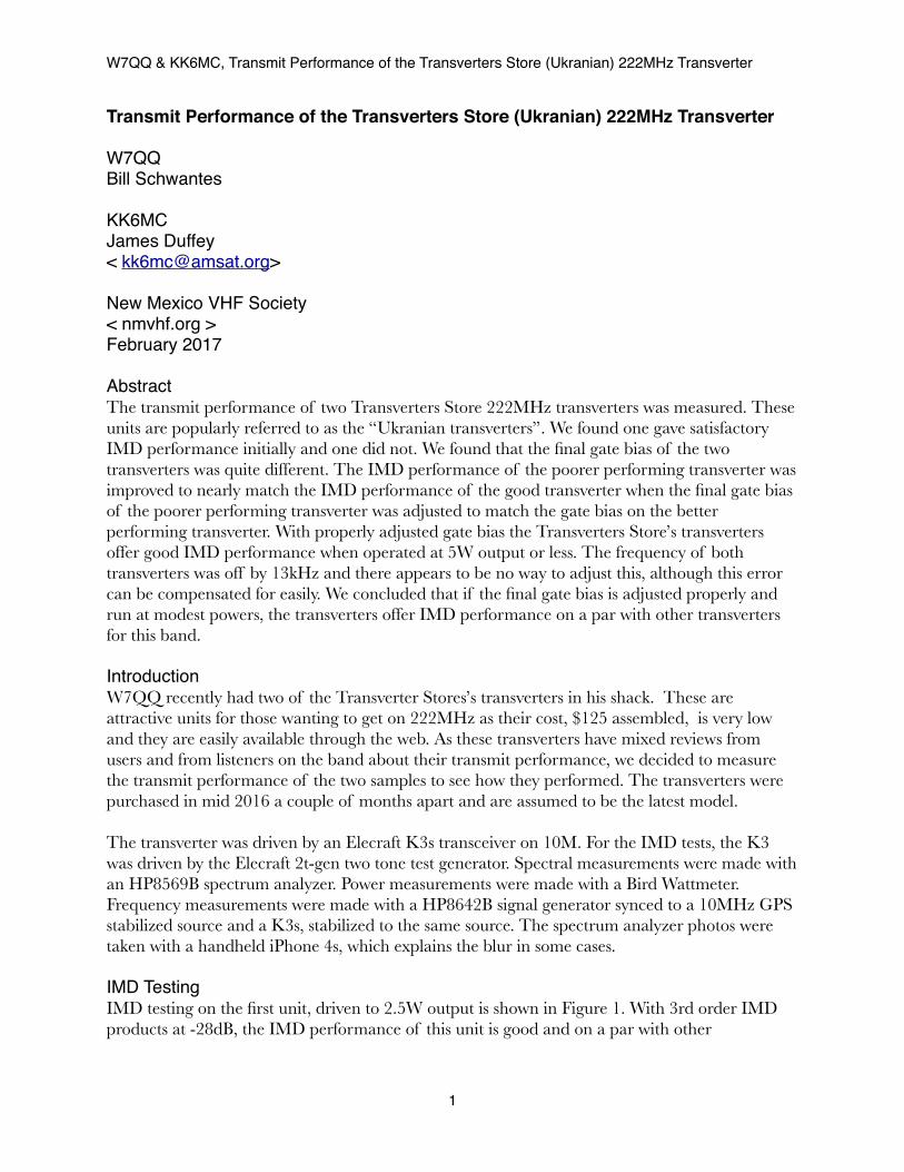
Transmit Performance of the Transverters Store (Ukranian) 222MHz Transverter
W7QQBill Schwantes
KK6MCJames Duffey< [email protected]>
New Mexico VHF Society< nmvhf.org >February 2017
AbstractThe transmit performance of two Transverters Store 222MHz transverters was measured. These units are popularly referred to as the “Ukranian transverters”. We found one gave satisfactory IMD performance initially and one did not. We found that the final gate bias of the two transverters was quite different. The IMD performance of the poorer performing transverter was improved to nearly match the IMD performance of the good transverter when the final gate bias of the poorer performing transverter was adjusted to match the gate bias on the better performing transverter. With properly adjusted gate bias the Transverters Store’s transverters offer good IMD performance when operated at 5W output or less. The frequency of both transverters was off by 13kHz and there appears to be no way to adjust this, although this error can be compensated for easily. We concluded that if the final gate bias is adjusted properly and run at modest powers, the transverters offer IMD performance on a par with other transverters for this band.
IntroductionW7QQ recently had two of the Transverter Stores’s transverters in his shack. These are attractive units for those wanting to get on 222MHz as their cost, $125 assembled, is very low and they are easily available through the web. As these transverters have mixed reviews from users and from listeners on the band about their transmit performance, we decided to measure the transmit performance of the two samples to see how they performed. The transverters were purchased in mid 2016 a couple of months apart and are assumed to be the latest model.
The transverter was driven by an Elecraft K3s transceiver on 10M. For the IMD tests, the K3 was driven by the Elecraft 2t-gen two tone test generator. Spectral measurements were made with an HP8569B spectrum analyzer. Power measurements were made with a Bird Wattmeter. Frequency measurements were made with a HP8642B signal generator synced to a 10MHz GPS stabilized source and a K3s, stabilized to the same source. The spectrum analyzer photos were taken with a handheld iPhone 4s, which explains the blur in some cases.
IMD TestingIMD testing on the first unit, driven to 2.5W output is shown in Figure 1. With 3rd order IMD products at -28dB, the IMD performance of this unit is good and on a par with other
W7QQ & KK6MC, Transmit Performance of the Transverters Store (Ukranian) 222MHz Transverter
1
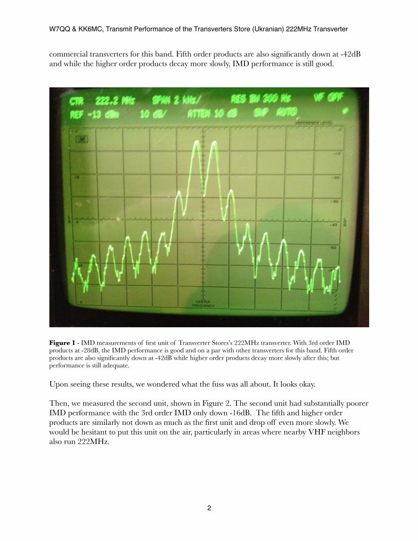
commercial transverters for this band. Fifth order products are also significantly down at -42dB and while the higher order products decay more slowly, IMD performance is still good.
Figure 1 - IMD measurements of first unit of Transverter Stores’s 222MHz transverter. With 3rd order IMD products at -28dB, the IMD performance is good and on a par with other transverters for this band. Fifth order products are also significantly down at -42dB while higher order products decay more slowly after this; but performance is still adequate.
Upon seeing these results, we wondered what the fuss was all about. It looks okay.
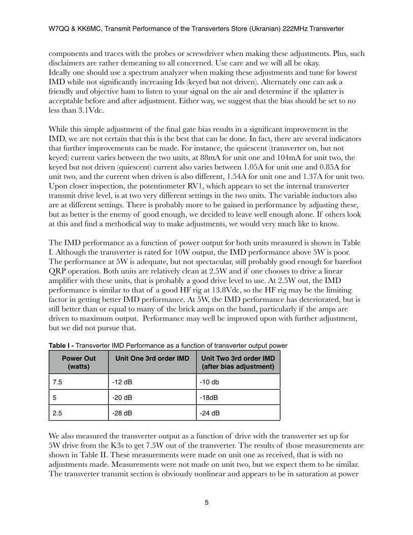
Then, we measured the second unit, shown in Figure 2. The second unit had substantially poorer IMD performance with the 3rd order IMD only down -16dB. The fifth and higher order products are similarly not down as much as the first unit and drop off even more slowly. We would be hesitant to put this unit on the air, particularly in areas where nearby VHF neighbors also run 222MHz.
W7QQ & KK6MC, Transmit Performance of the Transverters Store (Ukranian) 222MHz Transverter
2

Figure 2 - IMD measurements of the second unit of Transverter Stores’s 222MHz transverter. With 3rd order IMD products at -16 dB, the IMD performance is poor and one should think twice about putting this on the air. Fifth order products are only down -31dB and the higher order products are also substantially higher than the first unit measured and don’t drop off at all.
We set out to find out why these two units had such different IMD performance. The gate bias on the MOSFET final seemed like a good place to start looking, as with insufficient bias the final would not be operating in a linear mode. The RD15HVF1 MOSFET final has a good reputation for putting out clean signals, so we felt that the transverter transmit design itself was not responsible for the poor performance, particularly given the performance of unit one. Sure enough, the gate bias measured between the two units showed a significant difference--unit one, the good unit, was biased at 3.1Vdc and unit two, the poor unit, was biased at 2.8Vdc. When unit two was readjusted using RV2, the third order IMD dropped to -24dB, which is a significant improvement and can be put on the air without great concern for polluting the band. The RD15HVF1 data sheet shows the transition to linear behavior occurs above 3Vdc Vgs for 10Vdc Vds. With higher Vds the transition may well be higher, although no data is available. So, the behavior observed is not surprising.
W7QQ & KK6MC, Transmit Performance of the Transverters Store (Ukranian) 222MHz Transverter
3

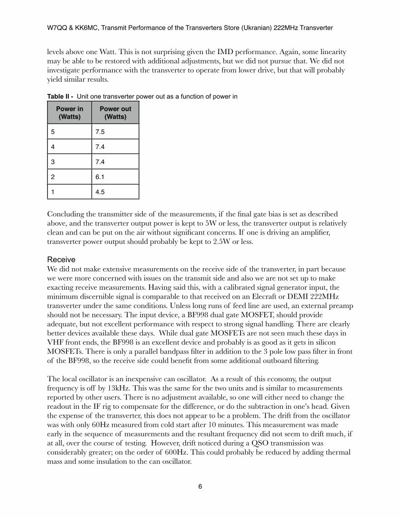
Measure Gate Voltage Here
Adjust Gate Voltage here. Start with 3.1VFigure 3 - The board layout for the 222MHz transverter, showing the locations where the gate voltage can be measured and the potentiometer used to set the bias adjusted. Caution should be used in making these measurements and adjustments, as the unit must be adjusted with the power on; but as long as normal care is used, there should be no problem in making this adjustment. Be careful that the probe used to measure the gate bias does not contact other PCB traces or components. Board layout from <http://transverters-store.com/222mhz/transverter%20222mhz1.jpg > with adjustment notations added. Although the PCB in the figure is labeled 144MHz, the board layout for the 222MHz transverter is nearly identical.
The final gate bias can be adjusted with a voltmeter, preferably a DMM or VTVM and a small screwdriver for the potentiometer. The locations of the pin on which to make the final gate bias is shown in Figure 3, as is the potentiometer which changes the voltage. The source of the RD15HVF1 is grounded, so any ground point will do for the negative meter lead. Normal caution should be used in making this measurement and adjustment, as the unit must be adjusted with the power on. As long as normal care is used, there should be no problem in making this adjustment by any reasonably capable ham who can use a meter to measure voltage and a screwdriver to adjust a potentiometer. Be careful that the probe used to measure the gate bias does not contact other PCB traces or components. Usually you would see a disclaimer here saying that we are not responsible for any damage that may occur if you perform this adjustment, but in reality, we don’t see how you can screw things up, as long as you don’t touch any
W7QQ & KK6MC, Transmit Performance of the Transverters Store (Ukranian) 222MHz Transverter
4
components and traces with the probes or screwdriver when making these adjustments. Plus, such disclaimers are rather demeaning to all concerned. Use care and we will all be okay. Ideally one should use a spectrum analyzer when making these adjustments and tune for lowest IMD while not significantly increasing Ids (keyed but not driven). Alternately one can ask a friendly and objective ham to listen to your signal on the air and determine if the splatter is acceptable before and after adjustment. Either way, we suggest that the bias should be set to no less than 3.1Vdc.
While this simple adjustment of the final gate bias results in a significant improvement in the IMD, we are not certain that this is the best that can be done. In fact, there are several indicators that further improvements can be made. For instance, the quiescent (transverter on, but not keyed) current varies between the two units, at 88mA for unit one and 104mA for unit two, the keyed but not driven (quiescent) current also varies between 1.05A for unit one and 0.85A for unit two, and the current when driven is also different, 1.54A for unit one and 1.37A for unit two. Upon closer inspection, the potentiometer RV1, which appears to set the internal transverter transmit drive level, is at two very different settings in the two units. The variable inductors also are at different settings. There is probably more to be gained in performance by adjusting these, but as better is the enemy of good enough, we decided to leave well enough alone. If others look at this and find a methodical way to make adjustments, we would very much like to know.
The IMD performance as a function of power output for both units measured is shown in Table I. Although the transverter is rated for 10W output, the IMD performance above 5W is poor. The performance at 5W is adequate, but not spectacular, still probably good enough for barefoot QRP operation. Both units are relatively clean at 2.5W and if one chooses to drive a linear amplifier with these units, that is probably a good drive level to use. At 2.5W out, the IMD performance is similar to that of a good HF rig at 13.8Vdc, so the HF rig may be the limiting factor in getting better IMD performance. At 5W, the IMD performance has deteriorated, but is still better than or equal to many of the brick amps on the band, particularly if the amps are driven to maximum output. Performance may well be improved upon with further adjustment, but we did not pursue that.
Table I - Transverter IMD Performance as a function of transverter output power
Power Out (watts)
Unit One 3rd order IMD Unit Two 3rd order IMD (after bias adjustment)
7.5 -12 dB -10 db
5 -20 dB -18dB
2.5 -28 dB -24 dB
We also measured the transverter output as a function of drive with the transverter set up for 5W drive from the K3s to get 7.5W out of the transverter. The results of those measurements are shown in Table II. These measurements were made on unit one as received, that is with no adjustments made. Measurements were not made on unit two, but we expect them to be similar. The transverter transmit section is obviously nonlinear and appears to be in saturation at power
W7QQ & KK6MC, Transmit Performance of the Transverters Store (Ukranian) 222MHz Transverter
5
levels above one Watt. This is not surprising given the IMD performance. Again, some linearity may be able to be restored with additional adjustments, but we did not pursue that. We did not investigate performance with the transverter to operate from lower drive, but that will probably yield similar results.
Table II - Unit one transverter power out as a function of power in
Power in (Watts)
Power out (Watts)
5 7.5
4 7.4
3 7.4
2 6.1
1 4.5
Concluding the transmitter side of the measurements, if the final gate bias is set as described above, and the transverter output power is kept to 5W or less, the transverter output is relatively clean and can be put on the air without significant concerns. If one is driving an amplifier, transverter power output should probably be kept to 2.5W or less.
ReceiveWe did not make extensive measurements on the receive side of the transverter, in part because we were more concerned with issues on the transmit side and also we are not set up to make exacting receive measurements. Having said this, with a calibrated signal generator input, the minimum discernible signal is comparable to that received on an Elecraft or DEMI 222MHz transverter under the same conditions. Unless long runs of feed line are used, an external preamp should not be necessary. The input device, a BF998 dual gate MOSFET, should provide adequate, but not excellent performance with respect to strong signal handling. There are clearly better devices available these days. While dual gate MOSFETs are not seen much these days in VHF front ends, the BF998 is an excellent device and probably is as good as it gets in silicon MOSFETs. There is only a parallel bandpass filter in addition to the 3 pole low pass filter in front of the BF998, so the receive side could benefit from some additional outboard filtering.
The local oscillator is an inexpensive can oscillator. As a result of this economy, the output frequency is off by 13kHz. This was the same for the two units and is similar to measurements reported by other users. There is no adjustment available, so one will either need to change the readout in the IF rig to compensate for the difference, or do the subtraction in one’s head. Given the expense of the transverter, this does not appear to be a problem. The drift from the oscillator was with only 60Hz measured from cold start after 10 minutes. This measurement was made early in the sequence of measurements and the resultant frequency did not seem to drift much, if at all, over the course of testing. However, drift noticed during a QSO transmission was considerably greater; on the order of 600Hz. This could probably be reduced by adding thermal mass and some insulation to the can oscillator.
W7QQ & KK6MC, Transmit Performance of the Transverters Store (Ukranian) 222MHz Transverter
6
The transverter did not get noticeably hot during the testing. The final is attached to the case for a heat sink, which appears to be more than adequate.
ConclusionsThese transverters offer good value for the money invested. Before putting one on the air, the final gate bias should be adjusted to 3.1Vdc or higher. We did not look extensively at harmonic or spurious emissions, and that is probably an area that we should revisit. Having said that, both transmit and receive performance could probably be improved by the use of external filtering, as the filtering included in the transverter is minimal.
The build quality of the printed circuit boards is very good. The assembly of the entire unit is of lower workmanship, but still acceptable. Given the disparities in potentiometer and variable inductor settings it appears that alignment is not consistent from unit to unit and this is an area for further investigation.
K5WO used unit two barefoot at 5W driven by an Icom 706 during the recent ARRL January VHF contest. His signal quality was good and not noticeably worse than other signals on the band. N5JEH also used one in the contest and it also sounded good. That is anecdotal information for sure, but if it had been bad, we would have noticed.
In short, these transverters are a good and inexpensive way to get on 222MHz. The DEMI and Elecraft transverters will still outperform them, in some areas by a great deal, but also at a greater expense. For the VHF operator who has never operated 222MHz before, these units provide a capability to get on the band with a minimum of effort. 222MHz offers many benefits: lower noise than 144MHz, more manageable high gain antennas, and less crowding. For the contester, adding 222MHz is a good way to boost the score, as there are more QSO points available on 222MHz than on two and six, and there is the opportunity for easily added multipliers. Also 222MHz is the base band for the UHF contest and is used to set up QSOes on other bands. Add a WA5VJB easy Yagi, < http://www.wa5vjb.com/yagi-pdf/cheapyagi.pdf >, and the investment to significantly increase one’s contest score is low.
The Transverters Store also sells transverters for 50MHz, 70MHz, 144MHz and 432MHz at similar prices. While we did not test transverters for those bands, the construction is similar for all of the units. Before using one of these transverters for another band, one should check the gate bias on the final.
Comments on this article are encouraged and should be directed to one or the other of the authors above. References and Notes1. A description of the transverters as well as the schematic and accompanying material is
available here: < http://transverters-store.com/222mhz.htm >2. These transverters can be purchased from the above web site or through eBay.
W7QQ & KK6MC, Transmit Performance of the Transverters Store (Ukranian) 222MHz Transverter
7
3. The data sheet for the RD15HVF1 is here: <https://www.mitsubishielectric-mesh.com/products/pdf/rd15hvf1.pdf >
4. These measurements have been taken with care but should not be considered gospel. We are trying to ascertain if these transverters could be put on the air with a relatively clean signal rather than trying to make exacting measurements. If anyone repeats these measurements, please share the results.
5. Our interest in these transverters is strictly technical. We want to see as many people as possible get on 222MHz, and this is an inexpensive way to invest in a new band. We receive no compensation from the Transverters Store and there are certainly better performing 222MHz transverters available on the market.
Appendix - What do these numbers mean with respect to others operating on 222MHz?We are writing this appendix to put the above numbers in perspective. The IMD numbers measured are in line with other VHF transverters, albeit most of those transverters operate at higher power levels and probably have better strong signal handling capabilities. See, for example, the QST product reviews of the DEMI 222-28 transverter in the July 2011 issue and the Elecraft XV144 in the October 2004 issue.
Brick amplifiers are often used on the VHF bands to increase the output power and coverage. As these brick amplifiers are easy to use, often just plug in and operate, many are operated at high levels of IMD, usually unknown to the operator. Sometimes this is the result of overdriving the amplifier and sometimes it is a result of poor amplifier design. The best of the brick amplifiers operate at an IMD level about the same as these transverters; the worst, and there are many of them out there, at 10dB worse than these transverters.
Given the above, the signal put out by these transverters will likely be no worse than most of the signals on 222MHz and better than many. Unless one has a very poor HF transceiver, the IMD of the transceiver will not limit the performance of these transverters.
W7QQ & KK6MC, Transmit Performance of the Transverters Store (Ukranian) 222MHz Transverter
8