Embed Size (px)
Citation preview

Title: PCSR – Sub-chapter 5.3 – Reactor Vessel
UKEPR-0002-053 Issue 06
Total number of pages: 43 Page No.: I / V
Chapter Pilot: F. GHESTEMME
Name/Initials
Date 23-11-2012
Approved for EDF by: A. MARECHAL Approved for AREVA by: G. CRAIG
Name/Initials
Date 23-11-2012 Name/Initials
Date 23-11-2012
REVISION HISTORY
Issue Description Date
00 First issue for INSA information 11-12-2007
01 Integration of technical and co-applicant comments 29-04-2008
02 PCSR June 2009 update including:
- Clarification of text
- Inclusion of references
- Technical additions related to material chemical composition (new section 4.3), worldwide forging capabilities, ageing effects beyond 60 years (new section 4.2), welding configurations and characteristics and pressure-temperature limits determination
29-06-2009
03 Consolidated Step 4 PCSR update: - Minor editorial changes - Update and addition of references - Introduction of High Integrity Component (HIC) safety case (§3) - Addition of a new §7 to address the HIC fast fracture methodology - Reorganisation of sub-chapter in line with the new §7 :
o Deletion of fast fracture mechanical analysis (previously §6.1) replaced by the new fast fracture analysis (§7.1)
o Inclusion of material irradiation monitoring part (previously §6.2.1) in the new fast fracture §7
o Inclusion of pressure and temperature limitation (previously §6.3) in the new fast fracture §7
o Deletion of fast fracture criteria related to appendix ZG of RCC-M code in §4.2; replaced by criteria given in §7
o Deletion of details on DMW (previously §7.3.2) o Inclusion of In-Service Inspection (previously §6.2.2) in the
manufacture and procurement section (§6.3) Continued on next page
31-03-2011

Title: PCSR – Sub-chapter 5.3 – Reactor Vessel
UKEPR-0002-053 Issue 06 Page No.:
II / V
REVISION HISTORY
Issue Description Date
03 cont’d
Consolidated Step 4 PCSR update: - Inclusion of information on calculations of anticipation factors,
based on dpa (§7.4) - Summary of Pressure-Temperature curve calculations added
(§7.5)
04 Consolidated PCSR update: - References listed under each numbered section or sub-section
heading numbered [Ref-1], [Ref-2], [Ref-3], etc - Minor editorial changes - Clarification of text (§3.1.2, §4.1, §6.1, §6.2, §6.3) - Update of references (§7) - Clarification of FMA scope (§7.1) - Update of avoidance of fracture demonstration of Dissimilar Metal
Weld (§7.2) - Update of text regarding implications of change in neutron energy
spectrum caused by the heavy reflector (§7.4)
27-06-2012
05 Consolidated PCSR update: - Update of references (§7.1, §7.5)
30-08-2012
06 Consolidated PCSR update: - Sub-chapter 5.3 - Figure 6 and section 7.5) updated consistent with
monophasic start-up
23-11-2012
Text within this document that is enclosed within curly brackets “{…}” is AREVA or EDF Commercially Confidential Information and has been removed.

Title: PCSR – Sub-chapter 5.3 – Reactor Vessel
UKEPR-0002-053 Issue 06 Page No.:
III / V
Copyright © 2012
AREVA NP & EDF All Rights Reserved
This document has been prepared by or on behalf of AREVA NP and EDF SA in connection with their request for generic design assessment of the EPRTM design by the UK nuclear regulatory authorities. This document is the property of AREVA NP and EDF SA. Although due care has been taken in compiling the content of this document, neither AREVA NP, EDF SA nor any of their respective affiliates accept any reliability in respect to any errors, omissions or inaccuracies contained or referred to in it. All intellectual property rights in the content of this document are owned by AREVA NP, EDF SA, their respective affiliates and their respective licensors. You are permitted to download and print content from this document solely for your own internal purposes and/or personal use. The document content must not be copied or reproduced, used or otherwise dealt with for any other reason. You are not entitled to modify or redistribute the content of this document without the express written permission of AREVA NP and EDF SA. This document and any copies that have been made of it must be returned to AREVA NP or EDF SA on their request. Trade marks, logos and brand names used in this document are owned by AREVA NP, EDF SA, their respective affiliates or other licensors. No rights are granted to use any of them without the prior written permission of the owner.
Trade Mark EPRTM is an AREVA Trade Mark.
For information address:
AREVA NP SAS
Tour AREVA 92084 Paris La Défense Cedex
France
EDF Division Ingénierie Nucléaire
Centre National d'Equipement Nucléaire 165-173, avenue Pierre Brossolette
BP900 92542 Montrouge
France

Title: PCSR – Sub-chapter 5.3 – Reactor Vessel
UKEPR-0002-053 Issue 06 Page No.:
IV / V
TABLE OF CONTENTS
1. DESCRIPTION
2. LIST OF OPERATING CONDITIONS
3. DESIGN PRINCIPLES AND OBJECTIVES
3.1. MAIN CHARACTERISTICS SELECTED
3.2. MAIN DIMENSIONS
3.3. MATERIALS
3.4. INSPECTION
3.5. DESIGN OF SUPPORTS
3.6. INTERFACES
4. MATERIALS
4.1. BASE METAL
4.2. MATERIAL AGEING
4.3. WELDS
4.4. OTHER RPV MATERIALS
5. MECHANICAL DESIGN
5.1. SIZING CALCULATIONS
5.2. DESIGN OF SUB-ASSEMBLIES
6. MANUFACTURE AND PROCUREMENT
6.1. COMPONENT PROCUREMENT
6.2. MANUFACTURING SEQUENCES
6.3. WELDING
7. FAST FRACTURE ANALYSIS
7.1. FRACTURE MECHANICS ANALYSIS
7.2. QUALIFIED NON-DESTRUCTIVE TESTING

Title: PCSR – Sub-chapter 5.3 – Reactor Vessel
UKEPR-0002-053 Issue 06 Page No.:
V / V
7.3 FRACTURE TOUGHNESS
7.4 MATERIALS IRRADIATION MONITORING
7.5. PRESSURE AND TEMPERATURE LIMITATIONS

PRE-CONSTRUCTION SAFETY REPORT CHAPTER 5: REACTOR COOLANT SYSTEM AND
ASSOCIATED SYSTEMS
SUB-CHAPTER: 5.3
PAGE : 1 / 38
Document ID.No. UKEPR-0002-053 Issue 06
SUB-CHAPTER 5.3 - REACTOR VESSEL
Sub-chapter 5.3 describes the reactor pressure vessel, including the design operating conditions, design requirements, materials used, and applicable mechanical design rules. A preliminary safety evaluation is given, including a description of the fracture mechanics analyses performed to assess the margins to fast fracture. In-service inspection requirements are given, together with manufacturing requirements.
1. DESCRIPTION
The Reactor Pressure Vessel (RPV) comprises two main components connected by closure components:
• The reactor vessel body,
• The vessel closure head.
The reactor vessel body consists of the following sections, welded together by circumferential welds:
The upper part is a single unit comprising a nozzle shell with an integral flange.
Upper part
The inner diameter of the flange is machined to form a support ledge for the reactor internal equipment. The flange is provided with threaded holes for the closure studs, and its upper surface is clad with stainless steel machined to provide a surface suitable for O-ring seals. The external seal ledge is welded to the external face of the flange. This piece is connected to the reactor cavity seal that ensures leak-tightness between the vessel flange and the bottom of the reactor cavity.
The nozzle shell includes eight penetrations to connect four loops of the reactor coolant system pipework. The wall of the shell is thickened to provide part-compensation for the nozzle openings. The nozzle shell is decreased in thickness at its lower end to match the core shell thickness thereby allowing a uniform butt weld. The nozzles are separate forgings welded onto the vessel using a set-on design. The whole of the RPV structure is supported by pads located on the bottom side of these eight nozzles. The support pads are integral with the nozzle forgings. These pads rest on a support ring, which is part of the RPV support structure.
The lower part of the reactor vessel body is made up of two core shells, a transition ring, and a lower head dome. These are all forged and are welded together by circumferential welds. The two cylindrical core shells encompass the active height of the core and are free from discontinuities. A forged transition ring provides the transition in thickness between the core shell and the lower head dome. It is welded to the lower shell of the core in an area of uniform cylindrical geometry, and to the lower head dome in an area of uniform thickness.
Lower part

PRE-CONSTRUCTION SAFETY REPORT CHAPTER 5: REACTOR COOLANT SYSTEM AND
ASSOCIATED SYSTEMS
SUB-CHAPTER: 5.3
PAGE : 2 / 38
Document ID.No. UKEPR-0002-053 Issue 06
Eight radial guides are welded to the inner face of the transition ring. Four of these guides ensure the alignment of the lower core internals. All eight provide a secondary support to the core in order to limit the consequences of a postulated failure of the lower internal support structures.
The vessel closure head is made up of two welded components:
Vessel closure head
• The vessel flange is a forged ring with holes for the closure studs. The lower face of the flange is clad with stainless steel which is grooved to form the recesses for two O-ring head seals.
• The head is a forged component, partially spherical in shape, penetrated by welded tubes which allow access to the RCCA drives and instrumentation, the sub-dome thermocouple guide tube and the venting tube.
Penetrations are shrink-fitted with adapter flanges for attachment of the CRDM housings. The same design is used for the instrumentation penetrations.
Four equally spaced lifting lugs are welded to the outer surface of the dome to enable handling.
The alignment and positioning of the RPV closure head and the internals on the RPV body is performed using a set of alignment pins located in notches in the RPV flange and in the RPV closure head flange.
All the internal surfaces of the RPV are clad with stainless steel.
Threaded fasteners provide the closure and integrity of the RPV by means of a number of stud-nut-washer sets. Studs are screwed into threaded holes in the RPV flange, and exert a pre-load on the vessel head using a nut-washer mechanism screwed onto them. The leak tightness between the vessel body and the vessel head is maintained by two O-rings located in the two circular recesses in the bottom face of the head flange.
Closure components
2. LIST OF OPERATING CONDITIONS
The transient conditions taken into account in the design of the reactor vessel are representative of the operating conditions occurring during operation of the plant. The RPV is designed for a 60-year operating life. The transients selected constitute a reference base for the evaluation of the reactor coolant system (RCP) [RCS] in order to ensure the integrity of the reactor coolant system equipment.
3. DESIGN PRINCIPLES AND OBJECTIVES
As stated in Sub-chapter 3.1, the Reactor Pressure Vessel (pressure boundary parts) is a High Integrity Component for which the specific measures described in section 0.3.6 of Sub-chapter 3.4 concerning prevention, surveillance and mitigation contribute to its high integrity demonstration.

PRE-CONSTRUCTION SAFETY REPORT CHAPTER 5: REACTOR COOLANT SYSTEM AND
ASSOCIATED SYSTEMS
SUB-CHAPTER: 5.3
PAGE : 3 / 38
Document ID.No. UKEPR-0002-053 Issue 06
Being a non-breakable component, the RPV satisfies the requirements described in section 6 of Sub-chapter 5.2.
3.1. MAIN CHARACTERISTICS SELECTED
A front elevation of the reactor pressure vessel is shown in Sub-chapter 5.3 - Figure 1.
3.1.1. Reactor Vessel body – Design of the core shells [Ref-1] [Ref-2]
The reactor pressure vessel core shell design is based on the dimensions of the core. The core comprises 241 fuel elements (in a 17x17 orthogonal grid with a pitch of 215.04 mm). The active height of the core is 4200 mm. The diameter of the core shells is designed to fulfil the design criterion for the core shell and the core shell weld such that the End of Life (EOL) transition temperature RTNDT EOL will be lower than 30°C. The inner diameter of the core shell is 4885 mm (without cladding). With this diameter, an end-of-life integrated flux of around 1.26 x 10¹⁹ n/cm2 (E > 1 MeV) is reached under the following conditions:
• 60-year operating life with a load factor of 0.9,
• An In-Out fuel management scheme, with U02 fuel assemblies,
• A core surrounded by a heavy reflector.
The design intent is achieved by verification that the EOL transition temperature RTNDT remains below 30°C.
The EOL fluence is lower for the German KONVOI RPV than for the EPR RPV: 0.5 x 10¹⁹ n/cm2 compared to 1.25 x 10¹⁹ n/cm2 for the EPR.
Comparison between KONVOI and EPR EOL fluences
Many characteristics vary significantly between the KONVOI and EPR RPVs. These differences have been examined in order to explain why it is not possible to achieve the same EOL fluence for neutrons with E > 1 MeV.
The comparison is made by firstly assuming that the flux levels (for neutrons having E > 1 MeV) are similar in both the KONVOI and EPR cores.
Based on a DORT propagation calculation, the neutron fast flux attenuation is greater in the KONVOI than in the EPR (by a factor about 2.3). This is due to the presence of a larger water gap in the KONVOI (+ 160 mm). The difference in neutron fast flux attenuation is not fully compensated for by the absorption of the EPR heavy reflector:
Comparison of Water Gap and Heavy Reflector effects
So, on the RPV inner wall, ϕK = ϕEPR/2.3
The KONVOI and EPR EOL fluence, Φ, are given for 40 and 60 years of operation: 32 and 55 EFPY, respectively.
Lifetime correction impact

PRE-CONSTRUCTION SAFETY REPORT CHAPTER 5: REACTOR COOLANT SYSTEM AND
ASSOCIATED SYSTEMS
SUB-CHAPTER: 5.3
PAGE : 4 / 38
Document ID.No. UKEPR-0002-053 Issue 06
The lifetime correction modifies the relationship between ΦK and ΦEPR as follows:
ΦK = 32/55*ΦEPR/2.3
The EPR core (4500 MWTH) is designed to produce a higher thermal power than the KONVOI (3765 MWTH). This difference in thermal power causes a proportional variation of EOL fluence between the two RPVs:
Power Level Correction
ΦK = 3765/4500*32/55*ΦEPR/2.3
ΦK = 0.2 ΦEPR
At the design phase, the calculated KONVOI EOL fluence was 0.5 x 10¹⁹ n/cm2. In this calculation, low leakage fuel management was assumed. The calculation of KONVOI EOL fluence has been reviewed and is now is expected to be closer to 2.4 x 10¹⁸ n/cm2.
Calculation of EOL fluence ratio
The EOL fluence ratio between the KONVOI and EPR can therefore be calculated as follows:
ΦK = 2.4/12.5 ΦEPR
ΦK = 0.2 ΦEPR
In conclusion, there is a good correlation between the calculated ratio of expected KONVOI to EPR EOL fluence, and the value (0.2) obtained from the corrections made to take into account design differences. This conclusion explains why it is not ALARP to achieve ΦK = ΦEPR.
3.1.2. Reactor Vessel body – Design of the upper part [Ref-1] [Ref-2]
The upper part of the RPV is designed as a single forged unit to reduce the number of circumferential welds. The extra thickness at the flange level required for the closure sizing is also used at the level of the nozzle shell openings as reinforcement situated in the vessel wall rather than in the nozzle wall (to minimise machining and off-cuts) and to allow the use of set-on type nozzles (to minimise the thickness of the welded joints).
The nozzles themselves are welded to machined radial cylindrical projections integral with the forged nozzle shell. This facilitates an automatic welding process and the non-destructive examination of the nozzle welds.
The pressure loss at the inlet nozzles is minimised by providing an internal conical profile.
The difference in level between the nozzles centre line and the top of the active core has been considered with the objective of mitigating the consequences of core uncovery following postulated intermediate breaks.
The distance between the centre line of the nozzles and the seal face is fixed at b to limit the total height of the vessel and to take into account the limitation in ingot size for manufacture of the upper part in one block.
{CCI}

PRE-CONSTRUCTION SAFETY REPORT CHAPTER 5: REACTOR COOLANT SYSTEM AND
ASSOCIATED SYSTEMS
SUB-CHAPTER: 5.3
PAGE : 5 / 38
Document ID.No. UKEPR-0002-053 Issue 06
3.1.3. Reactor Vessel body – Design of the lower part
The lower part made up of the following elements:
• Two core shells,
• The transition ring,
• Lower head dome.
The two core shells are sized to satisfy the end-of-life RTNDT requirements and the height required for the fuel elements (active height of the core). The two core shells cover the active height of the core and are free from discontinuities.
The size of the appropriate forging for a core region without a weld has been discussed with one of the largest worldwide manufacturers and includes:
Sizing Considerations for a Single Piece Core Region
• The top and bottom rings of the forging which are to be removed, as per the qualification program required by RCC-M,
• Extra length (equal to thickness) for the integral thermal shield to ensure protection of the radiation surveillance program specimens during the quenching operation (part of the final quality heat treatment), as per the current practice for the present core shells.
The dimensions needed for such an integral forging are 6 m height and 5.15 m diameter.
The following figure illustrates an example of the possible forging dimensions which can be achieved, and highlights that such a forging is currently outside of the capability of one of the largest worldwide manufacturers.
In all French RPVs, due to the high quality of the weld metal, the EOL RTNDT is always governed by the properties of the base metal. However, the weld metal is also included in the radiation surveillance program.

PRE-CONSTRUCTION SAFETY REPORT CHAPTER 5: REACTOR COOLANT SYSTEM AND
ASSOCIATED SYSTEMS
SUB-CHAPTER: 5.3
PAGE : 6 / 38
Document ID.No. UKEPR-0002-053 Issue 06
Integral Core Shell
Figure: Example of forging size capabilities of one of the largest worldwide manufacturers
Because of the size limitations during the forging processes, the presence of a weld in the core region is unavoidable. However, a number of points ensure that the weld in the sensitive area is safe:
• The EOL transition temperature RTNDT has been significantly lowered,
• Fast fracture design analysis shows there is no risk of fast fracture in this weld and in the core shells,
• Fabrication and control processes ensure high quality standards,
• Monitoring surveillance programme includes this weld.

PRE-CONSTRUCTION SAFETY REPORT CHAPTER 5: REACTOR COOLANT SYSTEM AND
ASSOCIATED SYSTEMS
SUB-CHAPTER: 5.3
PAGE : 7 / 38
Document ID.No. UKEPR-0002-053 Issue 06
The bottom head dome has a spherical shape, and is connected to the vessel body by means of the transition ring. The lower head is sized with the same inner radius as the upper head (for forging-related reasons). Because nothing penetrates the lower head, no openings are required. In addition, the height between the bottom of the core support plate and the bottom of the vessel has been reduced compared to the previous design (to limit the volume of the accumulators).
A forged transition ring provides the transition in thickness between the core shell and the lower head dome. Radial guides are welded on the inside face of the transition ring.
3.1.4. Design of RPV closure head [Ref-1] [Ref-2]
The thickness and the height of the head flange take into account the following:
• The maximum ingot size that can be procured,
• Limitation of the stresses at the junction with the upper head dome.
The closure head has the same inside spherical radius as the lower head of the RPV lower part. The opening angle is adjusted, taking into account:
• The size of the flange,
• The height of the closure head,
• The location of the CRDM, instrument and measurement adapters.
The thickness of the closure head was determined by the required reinforcement of the wall to compensate for the penetrations in the dome for the adapter assemblies for CRDMs, instrumentation, and measurements. The upper head wall thickness is b.
The closure head is provided with penetrations for:
• 89 adapters (CRDMs),
• 16 adapters for instrumentation (12 for neutron and thermal instruments, four for measurements of the reactor vessel water level),
• One special adaptor for RPV closure head dome temperature measurement probe,
• One vent pipe.
3.2. MAIN DIMENSIONS
The main dimensions of the RPV are given in Sub-chapter 5.3 - Figures 1 to 5 and repeated in Sub-chapter 5.3 - Table 1.
3.3. MATERIALS
The choice of the materials, their manufacture and their mechanical properties conforms to the RCC-M Code, Materials Section. The base metal used is the standard 16 MND 5 low alloy ferritic steel (French designation).
{CCI}

PRE-CONSTRUCTION SAFETY REPORT CHAPTER 5: REACTOR COOLANT SYSTEM AND
ASSOCIATED SYSTEMS
SUB-CHAPTER: 5.3
PAGE : 8 / 38
Document ID.No. UKEPR-0002-053 Issue 06
3.4. INSPECTION
During manufacture, the RPV joints can be inspected from both sides and the inspection will be performed in compliance with the RCC-M code requirements.
When the vessel is in service, the vessel body has to be inspected from the inside because insulation surrounds the outside surface of the vessel. All welds and other special areas to be monitored are accessible from inside the vessel.
3.5. DESIGN OF SUPPORTS
The RPV is supported on pads located under the eight RPV nozzles connected to the main reactor coolant system pipework. These support pads are integral with the nozzles and rest on a support ring (see section 9 of Sub-chapter 5.4). The nozzle thickness is sized taking into account both design conditions and severe accident conditions. Vertical motion of the RPV during a severe accident is restrained by the coolant system loops.
3.6. INTERFACES
The main interfaces between the RPV and other equipment are listed and described as follows:
3.6.1. Interface with RPV internals
• RPV flange and ledge (upper and lower internals flanges and alignment pins):
A support on the inner side of the RPV flange allows rapid positioning of both the lower and upper internals during refuelling operations. The ledge that provides this support is machined on the inner diameter of the flange. The RPV closure head is positioned on the RPV body by alignment pins located in notches in the RPV flange and in the RPV closure head flange.
• Interface with RPV core barrel outlet nozzles:
A pad machined on the inner contour of the RPV outlet nozzle ensures that at hot conditions the gap between the pad and the core barrel outlet nozzle limits the bypass flow to the required values. At cold conditions, the gap is large enough to allow the removal of the lower internals.
• Interface with lower radial guides (radial support keys and lower core support plate):
The lower internals are centred in the RPV by radial guides located on the transition ring of the RPV body. These guides allow radial and vertical differential thermal expansion. They also provide tangential restraints as well as secondary supports to prevent accidental motion of the RPV internals [Ref-1].
3.6.2. Control rod drive mechanism (CRDM) assemblies
• RPV CRDM adapter flange (for CRDM latch housing):
The 89 CRDM adapters [Ref-1] [Ref-2] consist of tubes welded into the RPV closure head spherical shell and flanges on which the CRDM latch housings are bolted. Circular metallic seals ensure the seal function between the flanges.

PRE-CONSTRUCTION SAFETY REPORT CHAPTER 5: REACTOR COOLANT SYSTEM AND
ASSOCIATED SYSTEMS
SUB-CHAPTER: 5.3
PAGE : 9 / 38
Document ID.No. UKEPR-0002-053 Issue 06
3.6.3. RPV instrumentation assembly
• RPV Aeroball and power density detectors (PDD) adapters,
• RPV water level measurement adapters.
Each of the 16 instrumentation [Ref-1] [Ref-2] adapters consists of a tube and a flange that is designed specifically for the connection to the Aeroball flux measuring system, a PDD core instrumentation column assembly, or a water level measurement probe. The inside contour of the adapter flange is threaded for connection to the instrumentation assembly. The seal arrangement at the upper end of these flange adapters consists of a welded Canopy seal. Removal of instruments occurs at the level of the instrumentation column.
Note: one specific penetration is foreseen for temperature measurements in the upper dome.
3.6.4. Vessel / concrete cavity connection
During unloading and reloading of the RPV core and internals, the reactor pool is filled with water. Provisions are made to ensure that the reactor cavity is leak-tight. Water tightness is ensured by the reactor cavity seal ring that is welded on the external seal ledge of the RPV flange on one side and on the pool liner on the other side.
3.6.5. Vessel / head equipment connection
The RPV closure head is provided with four lifting lugs for connection to the vertical rods of the RPV closure head-lifting device.
3.6.6. Vessel / multi-stud tensioning machine (MSTM)
Refuelling procedures require that the studs, nuts, and washers are removed from the reactor head using the MSTM. Use of the MSTM ensures that the reactor closure studs are never exposed to the borated water in the refuelling cavity.
The stud holes in the vessel flange are sealed using special plugs before the removal of the vessel head to prevent leakage of borated water into the threads.
4. MATERIALS
4.1. BASE METAL
16 MND 5 Low-alloy ferritic steel [Ref-1] is used for the shells, flanges, transition ring, nozzles, and hemispherical heads.

PRE-CONSTRUCTION SAFETY REPORT CHAPTER 5: REACTOR COOLANT SYSTEM AND
ASSOCIATED SYSTEMS
SUB-CHAPTER: 5.3
PAGE : 10 / 38
Document ID.No. UKEPR-0002-053 Issue 06
Volume II (materials) of the RCC-M contains a series of Part Procurement Specifications, each of which describes a specific material, for a given component and a given manufacturing process. In principle, a new Part Procurement Specification is introduced into the code every time a material or manufacturing process is changed. For cases where no specific Part Procurement Specification has been prepared, a more general Procurement Specification may apply. Part Procurement Specifications give the chemical composition, mechanical properties and heat treatment that are defined for the base metal. Some further restrictions or requirements may also be added in the Equipment Specifications, which are specific to a project.
Taking into account the requirements of RCC-M and of the Equipment Specifications of the EPR the chemical compositions defined differ from those of the ASTM standard in the following way [Ref-1]:
• Limitation of the upper carbon content threshold, for improved weldability and overall ductility,
• Reduction of the upper sulphur content limit to 0.005% for components not subject to irradiation (introduced in the Equipment Specification) as well as for components situated in the irradiated core area. This requirement limits the effects of anisotropy on the mechanical properties; the toughness of the upper shelf increases, in particular in the transverse direction (perpendicular to the main direction of deformation by hot working),
• In the active area of the core subject to high levels of irradiation (core shells), the copper and phosphorus contents are limited to 0.08% and 0.008% respectively. This requirement limits the effects of embrittlement by irradiation,
• Lowering of the phosphorus content limit to 0.008% for vessel components not subject to irradiation,
• Limitation of the upper limit for chromium and vanadium content. This requirement is related to reducing the risk of under-cladding cracking,
• Limitation of the cobalt content. This requirement is related to reducing the level of radiation on the vessel interior wall,
• A very low content of residual elements is also required in order to obtain the right properties for toughness and good weldability. Although no limit is explicitly defined in RCC-M, very low contents of Sb, As, Sn are obtained, through the selection of scrap material. B, Ti and Nb are not introduced into such steels and the limits of UK usage are not exceeded, although again they are not limited explicitly in RCC-M.
Notes:
(1) The upper limit on Si of UK usage is similar to the upper limit set by RCC-M.
(2) The Ca content is a consequence of the steelmaking practice and cannot be considered individually.
(3) The UK usage sets limits on carbon and chromium which are below those of ASME and RCC-M. The limits defined in RCC-M are necessary to ensure good hardenability and mechanical properties of the steel.

PRE-CONSTRUCTION SAFETY REPORT CHAPTER 5: REACTOR COOLANT SYSTEM AND
ASSOCIATED SYSTEMS
SUB-CHAPTER: 5.3
PAGE : 11 / 38
Document ID.No. UKEPR-0002-053 Issue 06
The manufacturing scheme is described in a Technical Manufacturing Programme. Precautions taken to avoid any risk of hydrogen defects are described in the Technical Manufacturing Programme. There is an upper limit of 1.5 ppm for hydrogen from either the ladle analysis or the part analysis. If the hydrogen analysis at this stage is above 0.8 ppm, a specific degassing treatment must be performed to bring the hydrogen value below this value.
After forging, the parts are subject to various heat treatments. The temperatures for the austenitising, tempering, and stress relieving processes are specified in each relevant Part Procurement Specification of RCC-M. More restrictive limitations can be introduced by the supplier in the Technical Manufacturing Programme, if required, to ensure that the correct properties are reached.
After the final heat treatment, the forgings are machined, and base material test specimens are taken. The tensile strength and toughness properties required are defined in the relevant Part Procurement Specifications of RCC-M. The general rule is to take specimens from the inner quarter thickness of shells and hemispherical heads. For other forgings with larger dimensions, the location of material test specimens depends on the particular component geometry and is specified in the relevant Part Procurement Specification.
Additional tests are required to determine the initial reference transition temperature. RTNDT, from the Nil Ductility Temperature (Pellini tests). An additional Charpy V-notch test serves as a benchmark to define the lower limit of the toughness curves.
For all forgings of the EPR RPV, the following values are required [Ref-1]:
• KV(0°C) ≥ 80 Joules average, 60 Joules individual value,
• Upper Shelf Energy ≥ 130 Joules,
• RTNDT ≤ -20°C.
The same requirements apply to the pressuriser, channel head, tubesheet and lower shell of the steam generators. For other parts of the steam generators, the values specified for KV (°C) and Upper Shelf Energy remain the same, but a value of -12°C is specified for RTNDT.
4.2. MATERIAL AGEING
The mechanisms for material ageing are identified. For the RPV beltline, the main ageing mechanism is from irradiation effects, which may generate point defects caused by displacement in the crystal lattice of atoms bombarded by incident neutrons.
The result for the RPV material is an increase in the yield strength, which raises the ductile to brittle transition temperature and thus entails an increased risk of fast fracture. The factors determining the amount of irradiation embrittlement have been well established for the low-alloy steel grades used for RPV construction and are covered by the RCC-M code. The maximum value of neutron fluence of 8 x 10¹⁹ neutrons/cm2 with E > 1 MeV used in determining irradiation embrittlement is far greater than the expected fluence for the EPR project, even in the case of life extension to 80 years.
During the RPV design stage, an analysis of the risk of fast fracture of the RPV is performed using material properties integrating ageing through formulas predicting irradiation embrittlement, and presented in section 7.1.

PRE-CONSTRUCTION SAFETY REPORT CHAPTER 5: REACTOR COOLANT SYSTEM AND
ASSOCIATED SYSTEMS
SUB-CHAPTER: 5.3
PAGE : 12 / 38
Document ID.No. UKEPR-0002-053 Issue 06
In addition, the actual embrittlement of the materials is measured periodically during service by mechanical tests carried out on test specimens inserted inside the RPV and subjected to a greater neutron flux than the vessel wall. The test specimens provide information on material ageing at an early stage, hence allowing the specified operating conditions to be updated if necessary. For example, increasing the safety injection water temperature in the unlikely case that the actual ageing is greater than anticipated at the design stage, and the safety margins listed above could no longer be achieved.
Although the transition between brittle behaviour and ductile behaviour is relatively steep, the evolution of the transition temperature RTNDT with time (i.e. with neutron fluence) is progressive. It is considered in RCC-M (ZG.6122) that the irradiation effect is proportional to the square root of the neutron fluence. The latest formulas expressed by EDF, based on results of surveillance programs give an envelope exponent of 0.59. The shift in transition temperature with time is thus very close to a square root law.
This means that an extension of the design life from 60 to 80 years would result in an increase of the transition shift by 15% of the calculated shift, which remains low compared to experience obtained on existing plants at the international level.
This, combined with the safety margins imposed at the design stage and the fact that the surveillance program will provide information on actual material ageing sufficiently in advance, guarantees that there are no unanticipated cliff edge effects which could impair vessel safety.
Moreover, toughness specimens are included in the surveillance program to obtain exactly the evolution of toughness properties with time, and an evaluation of the reference temperature RTT0 by applying the "Master Curve" concept according to ASTM E 1921 and the Code Case N 631 of the ASME Code. It has been proven that such a concept is useful for justifying life extension.
Other aspects are neglected when establishing design justifications, such as the Warm Pre-stress or constraint effect. Such effects are recognised in standards and could also be used in case of the need to justify life extension.
4.3. WELDS
Although limits set in RCC-M for residual elements in welding consumables are higher than those specified for base materials, and higher than those mentioned for UK usage, AREVA’s internal database shows that actual values are below the limits given for UK usage.
The following applies to the limit on nickel content in the beltline. The RCC-M formula for the prediction of irradiation embrittlement is calculated using base material data, and is over-conservative for the weld metal, up to a nickel content of 1.2% (hence the upper limit on Ni in welds in the beltline region). From AREVA records, the Ni content in RPV welds never exceeds 0.85%.
4.4. OTHER RPV MATERIALS
4.4.1. RPV cladding
The use of highly sensitised stainless steel as a material for manufacture of the pressure boundary is prohibited. Surface claddings in stainless steel are subject to sampling to ensure that the requirements relating to composition and delta ferrite are met.

PRE-CONSTRUCTION SAFETY REPORT CHAPTER 5: REACTOR COOLANT SYSTEM AND
ASSOCIATED SYSTEMS
SUB-CHAPTER: 5.3
PAGE : 13 / 38
Document ID.No. UKEPR-0002-053 Issue 06
A two layer stainless steel cladding is applied to the inner surface of the vessel wall. The first layer is 309L stainless steel grade and the second is 308L stainless steel grade.
The reason for applying a two layer cladding is to obtain a stainless steel surface with a low carbon content, which will not be sensitised during the stress relief treatment of the reactor vessel. To avoid hydrogen induced cracking in the Heat Affected Zone, all cladding operations are carried out with pre-heat maintained throughout the cladding process until a soaking treatment is carried out. In addition, overlap precautions are applied for the welding of the second layer to avoid any risk of reheat cracking during Post Weld Heat Treatments.
The thickness of the two layer deposit also allows the cladding surface to be ground to make the ultrasonic inspection of the interface between the base metal and the cladding easier.
4.4.2. RPV studs
The vessel studs are manufactured from high-strength bolting steel. Protection against the possible effects of corrosion is provided by the application of a manganese-based phosphate treatment. The mechanical properties of the steel 40NCDV7-03 are the following:
• Re min (20°C) = 900 MPa,
• Rm min (20°C) = 1000 MPa.
4.4.3. Vessel safe ends
Safe ends are welded to the RPV nozzles in the shop to avoid welding two dissimilar materials during the erection on site. The safe ends are manufactured from forged rings in Cr-Ni-Mo austenitic stainless steel and welded to the low alloy steel nozzle by a TIG narrow groove welding process using ER Ni-Cr-Fe 7 (Alloy 52) filler material, without any buttering. The inside surface of the low alloy steel nozzle is clad with stainless steel.
4.4.4. Vessel adapters and radial guides
Adapters and radial guides are both manufactured with a Ni-Cr-Fe alloy (NC30Fe, alloy 690). Alloy 690 grade is proposed because its thermal expansion coefficient is very close to that of the base material, its allowable stresses are near those of the base material (see Sub-Chapter 5.3 - Table 2) and because of its high resistance to stress corrosion cracking. These components are welded to the vessel using a Ni-Cr-Fe filler metal (Alloy 52).
5. MECHANICAL DESIGN
The mechanical design rules formulated in the RCC-M and the stress limits specified in Chapter B of the RCC-M are intended to prevent the following types of damage to the vessel [Ref-1]:
• Excessive deformation and plastic instability,
• Progressive deformation and fatigue cracking,
• Fast fracture.

PRE-CONSTRUCTION SAFETY REPORT CHAPTER 5: REACTOR COOLANT SYSTEM AND
ASSOCIATED SYSTEMS
SUB-CHAPTER: 5.3
PAGE : 14 / 38
Document ID.No. UKEPR-0002-053 Issue 06
The principle of analysis against the risk of fast fracture is presented in section 7 of this sub-chapter.
5.1. SIZING CALCULATIONS
The main objectives of the sizing calculations carried out during the EPR project design phase are to achieve a vessel design that ensures acceptance of the reference condition criteria (design pressure), relating to protection against the risk of excessive deformation and plastic instability.
This sizing includes the calculation of the minimum design thickness for all the main vessel sections and reinforcement calculations in the areas where openings are located (inlet and outlet nozzles and head dome penetrations). The design rules laid down in the RCC-M (Chapter I, Chapter B) are applied. The design pressure is 176 bar and the design temperature is 351°C [Ref-1].
b The studs are designed for the design pressure taking into account the hydrostatic force and seal reaction, as defined by RCC-M.
5.2. DESIGN OF SUB-ASSEMBLIES
5.2.1. RPV sub-assemblies involved in the analysis of accident loads
Vessel components, which may be additionally loaded in the event of accidents, are designed using criteria relating to the corresponding level conditions required by Chapter B, Part 1 of the RCC-M. The potentially affected RPV sub-assemblies concerned are:
• RPV nozzles and support pads,
• RPV radial guides located on the vessel transition ring,
• RPV adapters attached to the upper head dome.
The design thickness of the set-on nozzles is acceptable for accident situations (including Loss of Coolant Accidents (LOCA) or seismic loads).
{CCI Removed}

PRE-CONSTRUCTION SAFETY REPORT CHAPTER 5: REACTOR COOLANT SYSTEM AND
ASSOCIATED SYSTEMS
SUB-CHAPTER: 5.3
PAGE : 15 / 38
Document ID.No. UKEPR-0002-053 Issue 06
The radial guides are designed to take account of LOCA or seismic loads. Local stiffness at the level of the transition ring limits the stress levels in the vessel wall. The radial guides are also designed to resist an accidental drop of the RPV internals.
The design thickness of the adapters is acceptable under seismic loads.
5.2.2. Analyses of progressive deformation and fatigue cracking
Concerning prevention of progressive deformation and risk of fatigue cracking of the RPV, the approach is based on experience of conservative and known designs [Ref-1].
This is the case for all the main areas of the RPV where major discontinuities are encountered, except for the new design of the set-on nozzles that has required particular analyses.
Calculations have been performed to analyse the mechanical behaviour of the set-on nozzles. The analyses performed to evaluate the margins to the risk of progressive deformation and fatigue cracking demonstrate that the required criteria are fulfilled.
5.2.3. Assembly Drawings
Assembly drawings are given in Sub-chapter 5.3 - Figures 1 to 5.
6. MANUFACTURE AND PROCUREMENT
6.1. COMPONENT PROCUREMENT ([REF-1] TO [REF-7])
The main components of the RPV are produced by forging in accordance with the RCC-M requirements.
The RPV upper part can be manufactured from a 486 t ingot. The inside and outside profiles are machined from a single suitably shape piece. In this way, the reactor internals support ledge, the nozzle end face (inside), and the outside nozzle-connecting tab are all machined from a thick forged shell.
This upper section of the reactor pressure body has been subject to M140 qualification in accordance with RCC-M, the results of which provide assurance of the proper mechanical and metallurgical properties of the forging. These mechanical properties are partially conditioned by thermal treatment and quenching.
All the other vessel forgings need ingot weights less than 210 t. Conventional ingots (solid) are used to manufacture the vessel head flange, transition ring, and nozzles. Solid ingots will be used for the two core shells. Because of forging capabilities, two core shells are needed to cover the full core area. Directional solidification ingots can also be used for the manufacture of the hemispherical head forgings.
6.2. MANUFACTURING SEQUENCES [REF-1]
The manufacture of the vessel body is divided into two sub-assemblies:

PRE-CONSTRUCTION SAFETY REPORT CHAPTER 5: REACTOR COOLANT SYSTEM AND
ASSOCIATED SYSTEMS
SUB-CHAPTER: 5.3
PAGE : 16 / 38
Document ID.No. UKEPR-0002-053 Issue 06
The upper sub-assembly is made up of the upper part of the vessel and the eight safe ends and nozzles. An automatic submerged arc welding process (SAW) with a narrow groove weld edge preparation is used to weld each of the set-on type nozzles. Before assembly, each nozzle is provided with a stainless steel safe end. The safe-end welding operation is carried out by a narrow groove TIG welding process, using a Ni-Cr-Fe filler metal (690 alloy). The end of the nozzle and the safe end are not buttered before welding. This process provides good productivity and good ultrasonic test inspectability.
Upper sub-assembly
All the ferritic internal surfaces, the flange mating surface, and the flange upper surface, up to the seal ring location, are clad with high alloy stainless steel. Several processes are used for these cladding operations, such as automatic electro slag strip welding (ESW), hot-wire TIG welding and SMAW welding.
The lower sub-assembly is composed of the two core shells, the transition ring, and the hemispherical lower head. The two core shells are welded together using an automatic submerged arc welding process (SAW) with a narrow groove weld edge preparation. This assembly is completely clad (ESW) on the inside. In parallel, the radial guides are welded onto a buttering in Ni-Cr-Fe (690 alloy) filler metal made on the transition ring. Then the transition ring and the bottom head are clad and welded together, before the final weld between the lower core shell and the transition ring is made to complete the lower assembly.
Lower sub-assembly
The manufacturing of these two sub-assemblies is performed in parallel. Once completed, the two sub-assemblies are welded together.
The automatic SAW process is used for all full penetration girth welds and narrow groove is used for the weld preparation.
The RPV closure head is manufactured separately.
All the ferritic internal surfaces and the flange-mating surface are clad with stainless steel. Several processes are used for these cladding operations.
The head dome and the head flange are welded following an automatic submerged arc welding process (SAW) with a narrow groove weld edge preparation. The initial temperature RTNDT of this joint is specified to be less than -30°C.
Adapters are shrink fitted and welded (partial penetration weld type) on a Ni-Cr-Fe filler metal buttering (690 alloy).
6.3. WELDING
6.3.1. Main welding processes used in manufacturing [Ref-1]
The main welding processes used in manufacture are described below.

PRE-CONSTRUCTION SAFETY REPORT CHAPTER 5: REACTOR COOLANT SYSTEM AND
ASSOCIATED SYSTEMS
SUB-CHAPTER: 5.3
PAGE : 17 / 38
Document ID.No. UKEPR-0002-053 Issue 06
Circumferential welds for assembly are narrow groove full penetration welds and the submerged electro arc welding process with wire electrode is generally used. An automated welding process with accurate control of all parameters is implemented. The quality of the weld and the reliability of the equipment have been fully demonstrated by numerous examinations of circumferential welds performed in the past.
Narrow Groove Automatic Submerged Arc Welding (SAW)
For set-on nozzles, the welding process is qualified for ferritic welds manufactured for a thickness of around 180 mm and an angular joint of 10 degrees (angle between the weld axis and perpendicular to the nozzle wall). Based on the experience of the manufacturer and with a programme of qualification to be developed, this type of welding is performed to the same level of reliability as that currently expected for this type of joint.
Cladding process is provided using an automatic submerged arc welding process over the majority of the vessel inner surface using strip electrodes of given width (60 mm). This automated process is performed with manufacturing precautions in order to ensure:
Cladding process for stainless steel
• low dilution of the base material,
• high cleanliness and low hydrogen content of the stainless steel cladding.
The cladding process applied to the RPV cladding manufacture is fully qualified.
Narrow Gap Tungsten inert gas welding process
The bimetallic connection between the nozzle and the safe end is directly produced (without buttering) by a NGT in Ni-Cr-Fe (690 alloy). This type of connection is similar for all the bimetallic connections for the major components of the reactor coolant system of the EPR. Because of the absence of buttering and the small quantity of deposited metal, the narrow groove configuration provides significant operational simplicity, which reduces the risk of a technical welding defect.
(NGT)
The sketch below shows the welding configuration for the DMW (Dissimilar Metal Weld) in alloy 52 between the nozzle (low alloy steel with stainless steel cladding) and the safe-end (austenitic stainless steel).

PRE-CONSTRUCTION SAFETY REPORT CHAPTER 5: REACTOR COOLANT SYSTEM AND
ASSOCIATED SYSTEMS
SUB-CHAPTER: 5.3
PAGE : 18 / 38
Document ID.No. UKEPR-0002-053 Issue 06
Dimension X is approximately 10 mm.
The following DMW (Dissimilar Metal Weld) in alloy 52 are carried out:
• in the RPV: between the safe-end and the eight nozzles,
• in the steam generators: between the safe ends and the two primary nozzles,
• in the pressuriser:
o between the safe end and the vent nozzle,
o between the safe end and the surge nozzle,
o between the safe end and the safety valve nozzle,
o between the transition ring and the spray nozzle.
The differences between those DMW are the thickness of the nozzles:
Nozzle type RPV nozzles
SG nozzles
PZR vent nozzle
PZR surge nozzle
PZR safety valve
nozzle
PZR spray nozzle
Approximate thickness after
final machining
80 mm 100 mm 40 mm 50 mm 40 mm 30 mm

PRE-CONSTRUCTION SAFETY REPORT CHAPTER 5: REACTOR COOLANT SYSTEM AND
ASSOCIATED SYSTEMS
SUB-CHAPTER: 5.3
PAGE : 19 / 38
Document ID.No. UKEPR-0002-053 Issue 06
6.3.2. Heat treatments [Ref-1]
Welding and cladding operations on the base metal require special precautions relating to heat treatments. The sections to be assembled are preheated before and during the welding operation to a minimum temperature of 175°C to avoid cracking due to hydrogen in the HAZ (heat-affected zone).
After welding, the butt joints undergo one of the two following heat treatments:
• post heating (200°C minimum for at least 2 hours) allows the hydrogen to diffuse out of the heat-affected zone
• post weld heat treatment is performed in order to decrease the residual stresses, in particular related to weld contraction. This treatment also ensures hydrogen diffusion. It is performed at a temperature of 550±15°C for 1 to 5 hours depending on the wall thickness
In the final stage, the RPV is submitted to the final stress-relief heat treatment for 8 hours, at a temperature of between 595°C and 620°C. This treatment is performed at a lower temperature than the minimum tempering temperature (and allows for stress relaxation, without leading to a significant reduction in the mechanical properties).
6.3.3. Inspectability
6.3.3.1. Non-destructive testing during manufacturing
Several types of non-destructive tests are carried out during manufacturing.
Before welding, the weld edges will be subject to magnetic particle inspection. The same test is also applied on the inside surfaces of joint weld areas before cladding (examination by hot magnetic particle inspection). Liquid penetrant tests are also used on all other inner surfaces before cladding and for the weld preparations. These tests ensure that base material surface is free from defects, which could remain or which could develop due to their presence during the cladding operation. Liquid penetrant tests are also performed once the cladding is completed.
Examination of surface defects
The liquid penetrant test is also used for the final inspection of the adapter welds and for the radial guide welds.
According to the criteria defined in the RCC-M, Section S7000, any crack or linear indication type defects, detected by these two methods, will be subject to a repair procedure.
Once the stress-relief heat treatment is carried out, surfaces are inspected in accordance with the RCC-M (Section S7000).
It is required that all the full penetration girth welds are 100% inspected by ultrasonic tests (UT), before and after completion of the cladding.
Examination of volume defects
In addition to these inspections, the following areas are subject to ultrasonic inspections according to the RCC-M, after the final stress relief treatment is carried out:
PRE-CONSTRUCTION SAFETY REPORT CHAPTER 5: REACTOR COOLANT SYSTEM AND
ASSOCIATED SYSTEMS
SUB-CHAPTER: 5.3
PAGE : 20 / 38
Document ID.No. UKEPR-0002-053 Issue 06
• All full penetration ferritic pressure boundary welds,
• Cladding of the internal support ledge,
• Cladding of the head and vessel alignment pin location..
Ultrasonic examinations are performed with two types of scans:
• Scanning with transverse waves in a longitudinal direction along the weld, and in a transverse direction from both sides of the weld,
• Scanning with longitudinal waves, perpendicular to the surface of the complete weld area, from both sides, so that the heat-affected zone is covered by the examination.
The criteria applied are those of the RCC-M for all Class 1 components. Particular attention shall be paid to surface defects, which shall be repaired in all cases.
In addition to the ultrasonic examinations (UT), other methods of volume inspection (x-ray examinations or additional ultrasonic methods) may be required, as per the RCC-M.
For the RPV design, all the full penetration girth welds shall be 100% inspected by radiographic examination. Due to the wall thicknesses, a linear accelerator is used for the radiographic examinations.
The criteria applied are those of the RCC-M for all Class 1 components. Unacceptable defects are as follows:
• Cracking (including underclad cracking),
• Lack of penetration,
• Incomplete fusion,
• Undercutting,
• Gas cavity.
If any such defects are found, the manufacturer shall issue a non-conformity report and repair the defect in accordance with an approved repair procedure.
UK EPR specific inspections have been defined in the context of the safety demonstration of High Integrity Components, as described in section 7.2.
6.3.3.2. In-Service Inspection
The internal surface of the vessel may be inspected during the ten-yearly in-service inspections, using the In-Service Inspection Machine (MIS). The lower core support structure may be removed, making the entire internal surface of the vessel accessible.
The closure head is examined during each refuelling. Optical devices permit a selective inspection of the cladding and of the seal-seating surface.
The closure studs must be inspected periodically by visual examination, by dye penetrant tests and by eddy current tests.

PRE-CONSTRUCTION SAFETY REPORT CHAPTER 5: REACTOR COOLANT SYSTEM AND
ASSOCIATED SYSTEMS
SUB-CHAPTER: 5.3
PAGE : 21 / 38
Document ID.No. UKEPR-0002-053 Issue 06
During the detailed analysis, an « Initial Scheme of Maintenance » will be established for the in- service surveillance of the RPV and the closure head. This will allow a precise definition of the zones to be inspected and the types of NDE (non-destructive examination) to be used. All the following welds are accessible for in-service inspection:
• Vessel shells – from the inside surfaces,
• Reactor coolant nozzles – from the inside surfaces,
• Lower head – from the inside surfaces,
• Dissimilar welds between the reactor vessel nozzles and the reactor coolant pipework to examine the welds through the cladding from inside.
The design considerations that were incorporated into the system design to permit the above inspections are as follows:
• All reactor internals are completely removable,
• The closure head is stored dry on a stand during refuelling to facilitate direct visual inspection,
• All reactor vessel studs, nuts, and washers can be removed to dry storage during refuelling,
• The insulation covering the welds between nozzles and reactor coolant pipework may be removed.
The insulation of the bottom head has removable panels which provide access to enable visual inspection of the bottom head and can facilitate, if required, the installation on the outside of an automatic inspection device.
Access to the reactor vessel body is limited because of the radiation levels and remote underwater accessibility to this component. For these reasons, several steps have been incorporated in the design and manufacturing procedures to facilitate the periodic non-destructive tests, which the regulatory guides require. These are:
• In-shop ultrasonic examinations are performed on the most critical internally clad surfaces to assure an adequate cladding bond to allow later ultra-sonic testing of the base metal from the inside surface,
• The design of the reactor vessel core shell is an uncluttered cylindrical surface to allow future positioning of the test equipment without obstruction,
• The weld deposited clad surface on both sides of the welds to be inspected are specifically prepared to ensure the effectiveness of ultrasonic examinations,
• During fabrication, all full penetration ferritic pressure boundary welds are ultrasonically examined.
The vessel design and construction are intended to allow inspection as required by the regulations that apply to French nuclear power plants.

PRE-CONSTRUCTION SAFETY REPORT CHAPTER 5: REACTOR COOLANT SYSTEM AND
ASSOCIATED SYSTEMS
SUB-CHAPTER: 5.3
PAGE : 22 / 38
Document ID.No. UKEPR-0002-053 Issue 06
7. FAST FRACTURE ANALYSIS
As stated in Sub-chapter 3.1, the Reactor Pressure Vessel (pressure boundary parts) is a High Integrity Component for which the specific measures described in section 0.3.6 of Sub-chapter 3.4 concerning prevention, surveillance and mitigation contribute to its high integrity demonstration.
With regard to the fast fracture risk, the three-legged approach presented in Sub-chapter 3.4 section 1.6 has been applied to the RPV as follows:
• Use of fracture mechanics to determine the end of life limiting defect size and demonstration that the Defect Size Margin between this critical defect size and the detectable defect increased by fatigue crack propagation over the lifetime is larger than 2 as far as practicable.
This point is addressed in section 7.1.
• Use of suitable redundant and diverse inspections during manufacturing, supplemented by the use of qualified inspection(s) at the end of manufacturing.
This point is addressed in section 7.2.
• Verification of the lower bound fracture toughness values used to determine the critical defect size by measurements.
This point is addressed in section 7.3.
This methodology applies to the whole component, including welds and base metal. However, considering the higher probability of finding crack-like defects in welds than in forgings, and considering that the toughness of weld metal is lower, the majority of the locations assessed are likely to be the welds. Consequently the following sub-sections 7.1, 7.2 and 7.3 focus on welds, and the full demonstration including base metal (e.g. nozzle corners) will be provided in the detailed design stage.
The fracture toughness of the RPV core region material can be modified when submitted to irradiation. The monitoring of the RPV embrittlement materials performed to anticipate this damage is presented in section 7.4.
The verification that the UK EPR is operated within the limits of the RPV in terms of fast fracture is presented in section 7.5.
7.1. FRACTURE MECHANICS ANALYSIS
For the Reactor Pressure Vessel, the HIC methodology applies to the five circumferential welds, to the inlet and outlet set-on weld, and to the inlet and outlet Dissimilar Metal Weld (DMW) [Ref-1]. Four bounding or representative cases have been identified and fracture mechanics calculations have been performed on the most severe transients and mechanical loads:
• Core region circumferential weld,
• R/P closure head joint,
• Outlet set-on weld,
• Outlet Dissimilar Metal Weld.

PRE-CONSTRUCTION SAFETY REPORT CHAPTER 5: REACTOR COOLANT SYSTEM AND
ASSOCIATED SYSTEMS
SUB-CHAPTER: 5.3
PAGE : 23 / 38
Document ID.No. UKEPR-0002-053 Issue 06
For the homogeneous welds, the smallest End of Life Limiting Defect Size (ELLDS) is obtained for the core region weld and corresponds to an inner skin defect submitted to a main steam line break with loss of off-site power transient, which gives an ELLDS of 31 mm in the ductile range.
For the Dissimilar Metal weld, the bounding case corresponds to an inner skin defect submitted to a mechanical loading set including connected line break and earthquake, which gives an ELLDS of 23 mm in the ductile range.
The limiting defect size calculated ensures that the size of a critical defect that would lead to failure is above 20 mm. This defect size will be used for any of the RPV welds, DMW included, to define the requirements for inspections, which will be carried out at the end of manufacturing.
Fast fracture mechanics analyses will be performed in sensitive regions of the main forgings in the detailed design stage, to check whether these are limiting.
7.2. QUALIFIED NON DESTRUCTIVE TESTING
The NDT selected to be qualified for Reactor Pressure Vessel homogeneous welds are [Ref-1]:
Ferritic welds
• the pulse echo UT technique required by the RCC-M code supplemented with additional beam angles, and
• a UT specular reflection technique to detect near vertical defects.
The specular reflection tandem technique can be applied to all RPV ferritic welds – circumferential and set-on welds and is used to detect certain types of plausible defects such as near vertical defects, which may not be detected otherwise using conventional UT.
For the specific case of RPV thick welds which are cladded, qualified pulse echo UT will be applied before cladding from both faces and repeated after Stress Relieve Heat Treatment from the outside face only, as the control from the inside face cannot be performed with the cladding present.
The RT control required by the RCC-M code will continue to be applied extensively as stated above but as a non-qualified control before heat treatment on all RPV welds.
The sensitivity of the qualified pulse echo UT selected for RPV ferritic welds has been determined in the frame of In-Service Inspection (ISI) and enables detection of a flat bottom hole perpendicular to the beam axis with a diameter greater than 3.1 mm. The equivalent performance is the detection of a defect with a through wall extent of 3 mm and length 18 mm.
For circular welds, the qualified UT tandem technique increases the detection capability for smooth vertical defect through the whole thickness. Its sensitivity is based on a flat bottom hole of 6 mm and it has been demonstrated that this technique can detect and reject defects with 5 mm and 10 mm through wall extent.

PRE-CONSTRUCTION SAFETY REPORT CHAPTER 5: REACTOR COOLANT SYSTEM AND
ASSOCIATED SYSTEMS
SUB-CHAPTER: 5.3
PAGE : 24 / 38
Document ID.No. UKEPR-0002-053 Issue 06
The NDT selected to be qualified for the inspection of DMW is the manual pulse echo UT technique using longitudinal waves up to 70° refraction angle, deployed from inside the pipe for the detection of defects located on the inner half thickness of the weld and from outside the pipe for the detection of defects located on the outer half thickness of the weld, supplemented by a 0o LW reflexion technique from the pipe end [Ref-2]. These techniques can cover the volume of all welds and detect all defects of structural concern.
Dissimilar Metal Weld
The demonstration of performance of the UT selected for the inspection of dissimilar metal welds, and in particular their capability to detect the hypothetical narrow near-vertical planar weld defects, relies on the following evidence [Ref-2]:
• tests performed in the Sizewell qualification frame showing that defects embedded in a mock-up, including lack of fusion, could be detected using longitudinal waves up to 70° even when scanning only from the austenitic side of the weld – from ferritic side evidence presented in the previous section “ferritic HIC welds” are still valid.
• tests performed in the 1990’s and in 2011 on an AREVA DMW mock-up concluding that detection of the defects could be successfully achieved with the pulse echo technique, and that the detection of lack of fusion at the two fusion faces could be achieved when scanning with LW 0° from the end of the safe end; this inspection from the safe end provides a robust form of specular detection, and has been recognised as useful [Ref-2].
An ALARP analysis [Ref-3] summarised in section 3 of Sub-chapter 17.5 has been performed to support the adequacy of the UT proposal. The capability of this UT proposal to detect and reject defects whose Qualified Examination Defect Size (QEDS) derived from the fracture Mechanics Analyses is 10mm or greater can be achieved with a high level of reliability; smaller defects can also be detected with reasonable capability.
Finally a Defect Size Margin of 2 has been attained with Fracture Mechanics Calculations while considering that the fatigue crack growth for these worst case defects with regards to fast fracture is negligible, either for ferritic homogeneous weld or Dissimilar Metal Welds; this assumption will be verified during detailed design.
Conclusion
The UT techniques to be applied at the end of manufacturing will be qualified for any UK EPR project.
7.3. FRACTURE TOUGHNESS
The verification of the lower bound fracture toughness values used to determine the critical defect size will be performed [Ref-1]:
Base Metal - Ferritic welds
• for the base metal by measurements of the fracture toughness on the forgings of any UK EPR project, in the ductile range,
• for the weld material on a mock-up in the ductile range. The mock-up will be representative of the EPR material, either base metal (16MND5) or wire/flux.

PRE-CONSTRUCTION SAFETY REPORT CHAPTER 5: REACTOR COOLANT SYSTEM AND
ASSOCIATED SYSTEMS
SUB-CHAPTER: 5.3
PAGE : 25 / 38
Document ID.No. UKEPR-0002-053 Issue 06
The verification of the lower bound fracture toughness values used to determine the critical defect size will be performed by measurements of the fracture toughness on a mock-up representative of the EPR materials in the ductile range [Ref-1].
Dissimilar Metal Welds
7.4. MATERIALS IRRADIATION MONITORING
In the surveillance programme, the evaluation of radiation damage is based on pre-irradiation testing of Charpy V-notch and tensile and 1/2 T (thickness) compact (CTJ) specimens, and post-irradiation testing of Charpy V-notch, tensile, and 1/2 T (thickness) compact (CTJ) fracture mechanics test specimens. The programme is directed at evaluating the effect of irradiation on the fracture toughness of reactor vessel steels based on an approach combining transition temperature and fracture mechanics [Ref-1].
The vessel monitoring programme uses specimen capsules housed in holders attached to the outside of the internal vessel barrel, and positioned directly opposite the central section of the core. These capsules can be removed when the vessel head and the upper core support structure are removed. All capsules contain vessel steel specimens of the base metal of the two core shells of the reactor, of the core weld metal and of the associated heat-affected zone metal. Each capsule encloses tensile test specimens, Charpy V-notch specimens (which contain base metal, weld metal and metal from the heat-affected zone) and compact specimens. Archive materials are kept in sufficient quantities for additional capsules.
Activation and fission dosimeters are placed in drilled filler blocks. The dosimeters allow the evaluation of the fluence experienced by the specimens. In addition, thermal monitors made of low melting point alloys are included to monitor the maximum temperature of the specimens. The specimens are enclosed in a tight-fitting stainless steel sheath to prevent corrosion and ensure good thermal conductivity. The complete capsule is helium leak tested.
As part of the surveillance programme, a report presenting the chemical composition including residual elements will be provided for monitored materials and deposited weld metal.
The exposure of the specimens to neutrons occurs at a faster rate than that experienced by the vessel wall, as the specimens are located between the core and the vessel. Since these specimens experience accelerated irradiation and are actual samples from the materials used in the vessel, the transition temperature shift measurements between non-irradiated and irradiated specimens are representative of the vessel later in life. Data from CTJ compact specimens are expected to provide additional information to determine directly the fracture toughness of irradiated materials.
Correlations are established between the calculations of the integrated flux and the measurements of the irradiated samples in the surveillance capsules. The surveillance capsules are located within the reactor vessel so that the specimen irradiation history duplicates as far as possible, within the physical constraints of the system, the neutron spectrum, temperature history, and maximum neutron fluence experienced by the reactor vessel.
Due to the presence of the heavy reflector, the neutron energy spectrum is not strictly equivalent between the locations of the surveillance specimens and the RPV wall. The degree to which the heavy reflector and the specimen environment will induce a difference in neutron flux and energy spectrum between the two locations will be considered in the analysis of the surveillance specimen data.

PRE-CONSTRUCTION SAFETY REPORT CHAPTER 5: REACTOR COOLANT SYSTEM AND
ASSOCIATED SYSTEMS
SUB-CHAPTER: 5.3
PAGE : 26 / 38
Document ID.No. UKEPR-0002-053 Issue 06
A study has been performed [Ref-2], which presents calculations of anticipation factors based on dpa (displacements per atom), in addition to those based on the fast neutron flux (E > 1MeV). In this framework an approach to correlate the dpa and the damage measured on the irradiated samples has been proposed, in addition to that using fast neutron fluence as the dose parameter [Ref-3].
The schedule for the removal of the capsules for post-irradiation testing will account for the spectrum effect by considering the dpa as well as the fluence dose parameter. The detailed schedule will be given in the reactor vessel surveillance programme.
7.5. PRESSURE AND TEMPERATURE LIMITATIONS
Start-up and shutdown operating limits are based on the specified properties of the core region materials of the reactor pressure vessel.
The design operating curves are calculated assuming a period of reactor operation such that the beltline material will be limiting. Beltline material properties degrade with irradiation exposure, and this degradation is determined in terms of the adjusted reference nil-ductility temperature, which includes a reference nil-ductility temperature shift RTNDT
Predicted ΔRTNDT values are derived using two parameters, these being the effect of flux and the effect of copper and phosphorus contents on the shift of RTNDT for the materials located in the beltline region (base material and weld material).
Pressure / temperature curves are calculated according to RCC-M appendix ZG methodology, with a conventional quarter thickness defect located on the inner diameter of the core shells. The maximum fluence is determined for various selected time periods through the reactor life and the analysis is performed at the deepest point of the defect which covers the crack front intersection with the surface of the vessel wall.
A comparison between the operating domain and a Pressure-Temperature curve derived from a heat-up from 15°C to 303°C (with a gradient of 40°C/h) transient is given in Sub-chapter 5.3 - Figure 6 and shows that [Ref-1]:
• the P-T curve derived from fast fracture analysis does not result in a limitation for the operating domain, which arises from functional and fatigue aspects,
• there can be no interference between them even by pessimising the P-T curve by 10°C, 20°C or 30°C.

PRE-CONSTRUCTION SAFETY REPORT CHAPTER 5: REACTOR COOLANT SYSTEM AND
ASSOCIATED SYSTEMS
SUB-CHAPTER: 5.3
PAGE : 27 / 38
Document ID.No. UKEPR-0002-053 Issue 06
SUB-CHAPTER 5.3 - TABLE 1
Vessel Design Parameters [Ref-1]
General design - Type four loops - Number of control rod mechanism adapters 89 - Number of internal core instrumentation adapters 16 - Number of flange studs 52 Calculation and operating conditions - Design pressure 17.6 MPa abs. - Operating pressure 15.5 MPa abs. - Design temperature 351 °C - Temperature in the RCP [RCS] hot leg 328.1 °C - Temperature in the RCP [RCS] cold leg 295.5 °C Test conditions - Hydrostatic test pressure 25.1 MPa abs. - Hydrostatic test temperature RTNDT +30°C Sizes and weights - Inner diameter of the cylindrical vessel 4870 mm - Outer diameter of the flange 5750 mm - Largest diameter (for transport) 7470 mm - Total height of the lower section (from flange to bottom of dome) 10532.5 mm - Total height, head, control rod adapters and venting tube included 13722.5 mm - Core shells wall thickness b - Nominal Cladding thickness b - Vessel body weight 410 t - Vessel head weight 116 t - Weight of studs, bolts and washers 32 t
{CCI}
{CCI}
PRE-CONSTRUCTION SAFETY REPORT CHAPTER 5: REACTOR COOLANT SYSTEM AND
ASSOCIATED SYSTEMS
SUB-CHAPTER: 5.3
PAGE : 28 / 38
Document ID.No. UKEPR-0002-053 Issue 06
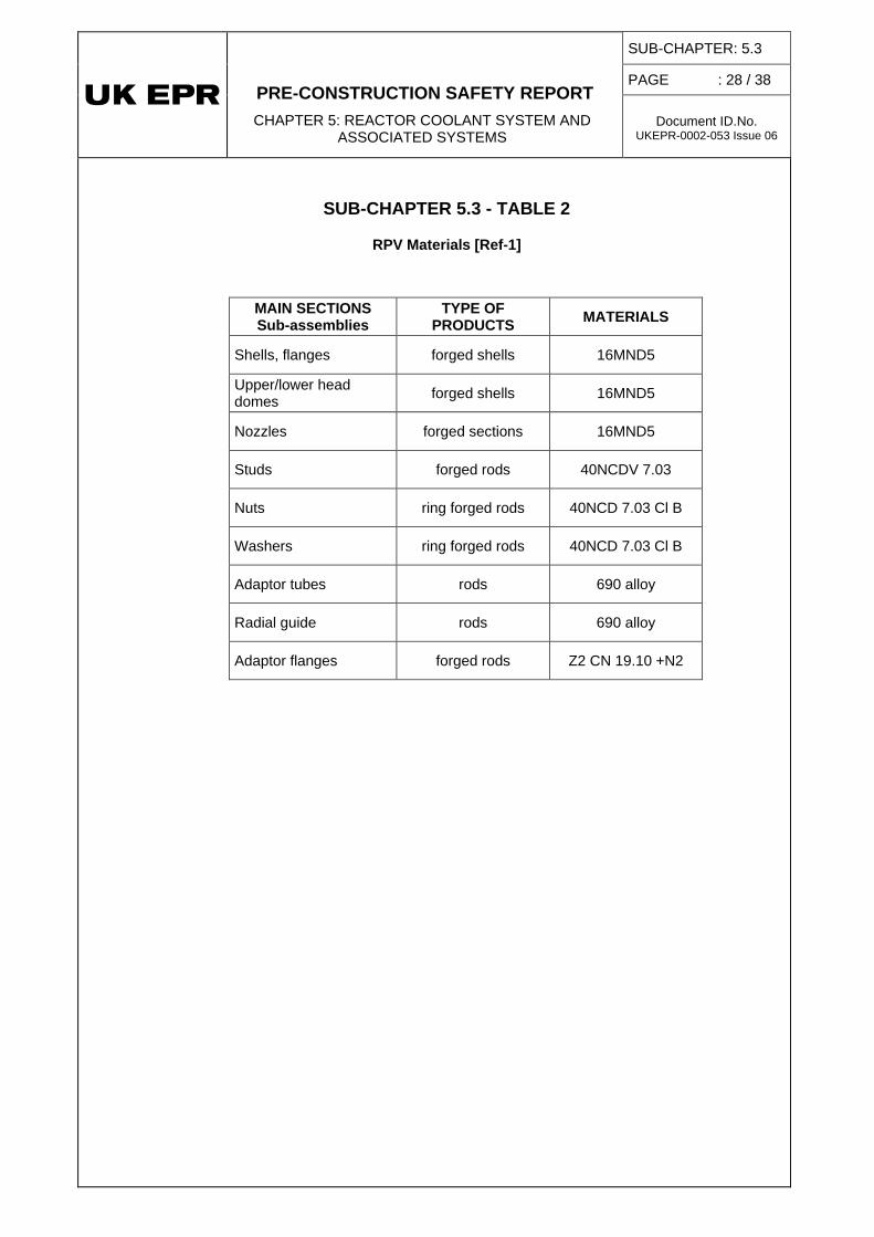
SUB-CHAPTER 5.3 - TABLE 2
RPV Materials [Ref-1]
MAIN SECTIONS Sub-assemblies
TYPE OF PRODUCTS MATERIALS
Shells, flanges forged shells 16MND5
Upper/lower head domes forged shells 16MND5
Nozzles forged sections 16MND5
Studs forged rods 40NCDV 7.03
Nuts ring forged rods 40NCD 7.03 Cl B
Washers ring forged rods 40NCD 7.03 Cl B
Adaptor tubes rods 690 alloy
Radial guide rods 690 alloy
Adaptor flanges forged rods Z2 CN 19.10 +N2

PRE-CONSTRUCTION SAFETY REPORT CHAPTER 5: REACTOR COOLANT SYSTEM AND
ASSOCIATED SYSTEMS
SUB-CHAPTER: 5.3
PAGE : 29 / 38
Document ID.No. UKEPR-0002-053 Issue 06
SUB-CHAPTER 5.3 - FIGURE 1 Front View of the RPV [Ref-1]

PRE-CONSTRUCTION SAFETY REPORT CHAPTER 5: REACTOR COOLANT SYSTEM AND
ASSOCIATED SYSTEMS
SUB-CHAPTER: 5.3
PAGE : 30 / 38
Document ID.No. UKEPR-0002-053 Issue 06
SUB-CHAPTER 5.3 - FIGURE 2 Top View of the RPV [Ref-1]

PRE-CONSTRUCTION SAFETY REPORT CHAPTER 5: REACTOR COOLANT SYSTEM AND
ASSOCIATED SYSTEMS
SUB-CHAPTER: 5.3
PAGE : 31 / 38
Document ID.No. UKEPR-0002-053 Issue 06
SUB-CHAPTER 5.3 - FIGURE 3 Nozzles Cross Section [Ref-1]

PRE-CONSTRUCTION SAFETY REPORT CHAPTER 5: REACTOR COOLANT SYSTEM AND
ASSOCIATED SYSTEMS
SUB-CHAPTER: 5.3
PAGE : 32 / 38
Document ID.No. UKEPR-0002-053 Issue 06
{CCI Removed}
b

PRE-CONSTRUCTION SAFETY REPORT CHAPTER 5: REACTOR COOLANT SYSTEM AND
ASSOCIATED SYSTEMS
SUB-CHAPTER: 5.3
PAGE : 33 / 38
Document ID.No. UKEPR-0002-053 Issue 06
SUB-CHAPTER 5.3 - FIGURE 5 Material List [Ref-1]
(For item definition, see Figure 1)

PRE-CONSTRUCTION SAFETY REPORT CHAPTER 5: REACTOR COOLANT SYSTEM AND
ASSOCIATED SYSTEMS
SUB-CHAPTER: 5.3
PAGE : 34 / 38
Document ID.No. UKEPR-0002-053 Issue 06
SUB-CHAPTER 5.3 - FIGURE 6 Pressure-Temperature Curve

PRE-CONSTRUCTION SAFETY REPORT
CHAPTER 5: REACTOR COOLANT SYSTEM AND
ASSOCIATED SYSTEMS
SUB-CHAPTER : 5.3
PAGE : 35 / 38
Document ID.No. UKEPR-0002-053 Issue 06
SUB-CHAPTER 5.3 – REFERENCES
External references are identified within this sub-chapter by the text [Ref-1], [Ref-2], etc at the appropriate point within the sub-chapter. These references are listed here under the heading of the section or sub-section in which they are quoted.
3. DESIGN PRINCIPLES AND OBJECTIVES
3.1. MAIN CHARACTERISTICS SELECTED
3.1.1. Reactor Vessel body – Design of the core shells
[Ref-1] EPR - RPV Mechanical dimensioning: NEER-F DC 19 Revision C. AREVA. May 2007. (E)
[Ref-2] FA3 RPV Equipment Specification. NFPMR DC 1145 Revision J. AREVA. March 2009. (E)
3.1.2. Reactor Vessel body – Design of the upper part
[Ref-1] EPR - RPV Mechanical dimensioning: NEER-F DC 19 Revision C. AREVA. May 2007. (E)
[Ref-2] FA3 RPV Equipment Specification. NFPMR DC 1145 Revision J. AREVA. March 2009. (E)
3.1.4. Design of RPV closure head
[Ref-1] EPR - RPV Mechanical dimensioning: NEER-F DC 19 Revision C. AREVA. May 2007. (E)
[Ref-2] FA3 RPV Equipment Specification. NFPMR DC 1145 Revision J. AREVA. March 2009. (E)
3.6. INTERFACES
3.6.1. Interface with RPV internals
[Ref-1] FA3 RPV Equipment drawing. NEER-F DB 1206 Revision D. AREVA. 2008. (E)
3.6.2. Control rod drive mechanism (CRDM) assemblies
[Ref-1] FA3 RPV Equipment Specification. NFPMR DC 1145 Revision J. AREVA. March 2009. (E)
[Ref-2] Reactor Pressure Vessel detailed drawing - CRDM and Instrumentation Adaptors. NEER-F DB 1204 Revision D. AREVA. September 2008. (E)

PRE-CONSTRUCTION SAFETY REPORT
CHAPTER 5: REACTOR COOLANT SYSTEM AND
ASSOCIATED SYSTEMS
SUB-CHAPTER : 5.3
PAGE : 36 / 38
Document ID.No. UKEPR-0002-053 Issue 06
3.6.3. RPV instrumentation assembly
[Ref-1] FA3 RPV Equipment Specification. NFPMR DC 1145 Revision J. AREVA. March 2009. (E)
[Ref-2] Reactor Pressure Vessel detailed drawing - CRDM and Instrumentation Adaptors. NEER-F DB 1204 Revision D. AREVA. September 2008. (E)
4. MATERIALS
4.1. BASE METAL
[Ref-1] FA3 RPV Equipment Specification. NFPMR DC 1145 Revision J. AREVA. March 2009. (E)
5. MECHANICAL DESIGN
[Ref-1] Definition of the hierarchy of the main reports relating to design and manufacture primary component. PEER-F 100134 Revision A. AREVA. March 2010. (E)
5.1. SIZING CALCULATIONS
[Ref-1] EPR - RPV Mechanical dimensioning: NEER-F DC 19 Revision C. AREVA. May 2007. (E)
5.2. DESIGN OF SUB-ASSEMBLIES
5.2.2. Analyses of progressive deformation and fatigue cracking
[Ref-1] FA3 - RPV Assessment of Sensitive Areas. NEER-F DC 77 Revision C. AREVA. April 2008. (E)
6. MANUFACTURE AND PROCUREMENT
6.1. COMPONENT PROCUREMENT
[Ref-1] FA3 RPV Equipment Specification. NFPMR DC 1145 Revision J. AREVA. March 2009. (E)
[Ref-2] Reactor Pressure Vessel: General Assembly. NFPMR-DB 1200 Revision G. AREVA. January 2009. (E)

PRE-CONSTRUCTION SAFETY REPORT
CHAPTER 5: REACTOR COOLANT SYSTEM AND
ASSOCIATED SYSTEMS
SUB-CHAPTER : 5.3
PAGE : 37 / 38
Document ID.No. UKEPR-0002-053 Issue 06
[Ref-3] Reactor Pressure Vessel detailed drawing - closure. NFPMR-DB 1201 Revision F. AREVA. November 2008. (E)
[Ref-4] Reactor Pressure Vessel: Inlet Nozzle - Outlet Nozzle. NFPMR-DB 1202 Revision G. AREVA. January 2009. (E)
[Ref-5] Reactor Pressure Vessel detailed drawing - radial guides. NEER-F DB 1203 Revision D. AREVA. September 2008. (E)
[Ref-6] Reactor Pressure Vessel detailed drawing - CRDM and Instrumentation Adaptors. NEER-F DB 1204 Revision D. AREVA. September 2008. (E)
[Ref-7] Reactor Pressure Vessel detailed drawing - vent pipe and dome thermocouple. NEER-F DB 1205 Revision D. AREVA. September 2008. (E)
6.2. MANUFACTURING SEQUENCES
[Ref-1] FA3 RPV Equipment Specification. NFPMR DC 1145 Revision J. AREVA. March 2009. (E)
6.3. WELDING AND NON-DESTRUCTIVE TESTING (NDT)
6.3.1. Main welding processes used in manufacturing
[Ref-1] FA3 RPV Equipment Specification. NFPMR DC 1145 Revision J. AREVA. March 2009. (E)
6.3.2. Heat Treatments
[Ref-1] FA3 RPV Equipment Specification. NFPMR DC 1145 Revision J. AREVA. March 2009. (E)
7. FAST FRACTURE ANALYSIS
7.1. FRACTURE MECHANICS ANALYSIS
[Ref-1] Demonstration of integrity of High Integrity Components against fast fracture. Fracture Mechanic Analyses – Non Destructive Testing – Fracture Toughness. NEER-F 10.2070 Revision D. AREVA. August 2012. (E)
7.2. QUALIFIED NON DESTRUCTIVE TESTING
[Ref-1] UK Technical report on the manufacturing non destructive testing to be qualified. PEEM-F.101134 Revision D. AREVA. December 2010. (E)
[Ref-2] Ultrasonic examination of MCL homogeneous and dissimilar metal welds. PEEM-F 11.0505 Revision C. AREVA. March 2012. (E)

PRE-CONSTRUCTION SAFETY REPORT
CHAPTER 5: REACTOR COOLANT SYSTEM AND
ASSOCIATED SYSTEMS
SUB-CHAPTER : 5.3
PAGE : 38 / 38
Document ID.No. UKEPR-0002-053 Issue 06
[Ref-3] UK EPR ALARP justification of manufacturing inspection techniques proposed for MCL welds of the UK EPR. PEER-F DC 78 Revision A. AREVA. March 2012. (E)
7.3. FRACTURE TOUGHNESS
[Ref-1] UK EPRTM Avoidance of Fracture- Fracture mechanics and minimum fracture toughness aspects: Materials Data. NEEM-F 10 0179 Revision E. AREVA. November 2010. (E)
7.4. MATERIALS IRRADIATION MONITORING
[Ref-1] RPV Irradiation surveillance program. NEER-F DC 25 Revision C. AREVA. 2008. (E)
[Ref-2] Evaluation of dpa rate on UK EPRTM RPV. PEPD-F 10.0428. AREVA. December 2010. (E)
[Ref-3] RPV irradiation surveillance programme (ISP) - Design Principles for UK. EPR H-T27-2012-00181 Revision 1.0. EDF. February 2012. (E)
7.5. PRESSURE AND TEMPERATURE LIMITATIONS
[Ref-1] Relation between operating domain and (P, T) curve issued from fast fracture analysis. NEER-F 100697 Revision A. AREVA. April 2010. (E)
SUB-CHAPTER 5.3 - TABLE 1
[Ref-1] EPR - RPV Mechanical dimensioning: NEER-F DC 19 Revision C. AREVA. May 2007. (E)
SUB-CHAPTER 5.3 - TABLE 2
[Ref-1] FA3 RPV Equipment Specification. NFPMR DC 1145 Revision J. AREVA. March 2009. (E)
SUB-CHAPTER 5.3 – FIGURES 1, 2, 3, 4 AND 5
[Ref-1] FA3 RPV Equipment Specification. NFPMR DC 1145 Revision J. AREVA March 2009. (E)


![PCSR – Sub-chapter 7.7 – I&C tools, development process ...epr-reactor.co.uk/ssmod/liblocal/docs/PCSR/Chapter 7...RRC-B SASand Process Information and Control System (MCP [PICS])](https://img.dokumen.tips/doc/110x75/6120260e89bb271b4759af47/pcsr-a-sub-chapter-77-a-ic-tools-development-process-epr-7-rrc-b.jpg)