Embed Size (px)
Citation preview

UK High Energy Physics developments for radiotherapy
Tony Price
University of Birmingham
PP Seminar
28th September 2016

Contents
Brief overview of radiotherapy
Motivation for proton therapy
The need for proton Computed Tomography (pCT)
The PRaVDA approach to pCT
SuperNEMO calorimeter for proton beam QA
CMOS MAPS for monitoring x-ray radiotherapy

UK Cancer Figures
Cancer is responsible for 1 in 8 deaths worldwide
In the UK alone there is 350,000 cases per year and 1 in 2 people will be affected by
cancer at some point in their lives
Most common cancers in the UK are Lung (22%), Colorectal (10%), Breast (8%),
Prostate (6%)
Overall survival rate in the UK is above 50%
Radiotherapy is used in 40% of all cancer treatment in the UK
In 2013 UK Gov. committed funds to build 2 proton therapy centres in the UK
London and Manchester NHS sites to open 2018/19
Also at least 5 private proton centres in the UK recently announced
06/11/2013 Proton Computed Tomography 3* http://www.planningforprotons.com/overview-of-radiotherapy/

What is Radiotherapy?
Radiotherapy uses radiation to kill the cancer cells
Energy is deposited in the cells which damages the DNA and stops the cells from
replicating
Surrounding healthy cells are also damaged so need to plan treatment to minimise the
dose to the healthy tissue and maximise to the cancer
High energy x-rays from linear accelerators to treat cancer deep inside a patient
Low energy x-rays and electrons to treat skin cancers
Proton/Ion beams which are accelerated using cyclotrons/synchrotrons
06/11/2013 Proton Computed Tomography 4

Radiotherapy: Treatment Planning
Whilst the survival rates associated with conventional radiotherapy are excellent there
is one major problem.
The interactions of photons within the body mean there is an unavoidable dose to the
healthy tissue whilst treating the tumour
Multiple beams and treatments are required in order to spare the healthy tissue and
maximise the dose to the tumour
This requires often complex treatment plans
To ensure that the radiotherapy is planned correctly it is essential to know
– where the tumour is located within the body?
– where are the essential organs which must be spared by the treatment?
– what is the distribution and amount of various tissues in the body?
06/11/2013 Proton Computed Tomography 5

Computed Tomography
Measure the flux of photons out of a patient as a function of position on a detector to
measure the linear attenuation coefficient along that path through patient (line integral)
Rotate the source and detectors around the patient and take another radiograph from
different angles.
Use a reconstruction algorithm to combine all of the line integrals as a function of
position in the patient
There are many ways to reconstruct the image from the line integrals
– Filtered back projection
– Taking Fourier transforms
– Iterative approaches
Many mathematicians still working on improving the CT algorithms but very good
images can be reconstructed currently.
06/11/2013 Proton Computed Tomography 6

Computed Tomography
06/11/2013 7

Proton Radiotherapy
A beam of photons will deposit energy all
along its path following an exponential
law
Charged particles lose energy via the
Bethe-Bloch formula and as such exhibit
a “Bragg Peak”
Position of BP set by initial particle energy
Most of the energy is deposited just
before a proton stops, leading to an
increased ratio of dose in the tumour to
dose in healthy tissue
Lower dose to healthy tissue reduces the
risk of complications in later life and
allows for treatment of cancers close to
critical organs
Proton Computed Tomography 806/11/2013

Compare proton and photon
06/11/2013 Proton Computed Tomography 9Medulloblastoma in a child

Blessing and a Curse
Whilst the Bragg peak is a blessing with
respect the sparing healthy tissue it can
also be a curse
Without accurately knowing the
materials which the protons traverse the
range can be set incorrectly
This could result in a huge dose to
healthy tissue or under dosing the
tumour
There are multiple sources of
uncertainty in the protons range
Proton Computed Tomography 1006/11/2013
Main uncertainty caused by imaging
the patient with x-rays but treating
with protons!

The need for pCT
Currently x-ray CT is
performed which is then
converted into stopping
powers using LUT
“The values recommended in this
study based on typical treatment sites
and a small group of patients roughly
agree with the commonly referenced
value (3.5%) used for margin design.”
M Yang et al PMB. 57 4095–4115 (2012)

The need for pCT
Current uncertainty in proton range is ~3.5%. If beam passes through 20cm
of tissue, then Bragg peak could be anywhere within +/- 7 mm
Aim to reduce proton range uncertainties to a ~1% – variation of +/- 2mm.
Simplified treatment plans – fewer beams; reduced probability of secondary
cancers induced; and treatments will be shorter

Methodology
“Proton radiography and tomography with application to proton therapy”,
Poludniowski et al, BJR 2015
Track proton in
Track proton out
Measure residual energy
Sounds easy right?
But…
Need information on all
protons
Require 10^9 protons per
image
Imaging time needs to be
of order minutes

Who are PRaVDA?
PRaVDA – Proton Radiotherapy Verification and Dosimetry Applications
Supported by the Wellcome Translation Award Scheme, Grant 098285.
Members from Academia, Industry, and the NHS

Silicon Strip Trackers
The PSDs in PRaVDA were developed
by University of Liverpool HEP Group
Manufactured by Micron Semiconductor
Strip Sensor Parameters:
• Active area of 93x96 mm2
• 150 um thick n-in-p silicon
• Strip pitch of 90.8 um
• Strip Length of 48 mm
• 2048 strips
• 1024 read out from each side
• 16 ASICs (8 for each strip half)
• Double threshold binary readout
Module construction and
wire bonding joint effort
between Liverpool and
new BILPA lab

x-u-v Orientation
Each tracking unit consists of 3 strip
sensors, rotated at 60 degrees to each
other
The x-u-v orientation reduces
ambiguities and allows for higher
occupancies in the trackers
Published Patent WO2015/189601

Range Telescope
Interweaved Si readout and PMMA
sheets
Final layer with a signal is used to
calculate range
CMOS or Strips option
CMOS with analogue readout would
allow interpolation between layers to
reconstruct BP
Strips readout at same speed as
trackers so reconstruction easier
PRaVDA constructed strip RT due to
constraints within project
x x x x xx
xx
x
x
x
Output Signal
Distance, xx

CMOS RT Measurements
Dynamite sensor measured at iThemba and UoB
Changing signal size in very good agreement with theory
Could use this to interpolate between final layers
Experimental data from Birmingham and IThemba, SA
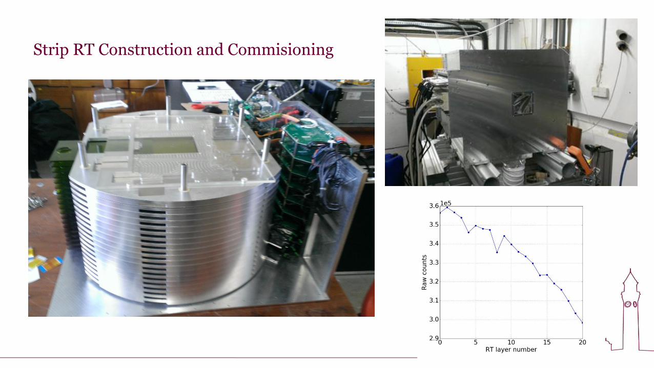
Strip RT Construction and Commisioning

Geant4 Simulations

iThemba Beamline
MC40 Beamline

Sensor Response
60 MeV p, PRaVDA strip sensor, ALiBaVa Readout 60 MeV p, PRaVDA CMOS sensor (Dynamite)

Cooling
Lot of heat to shift from boxes
Cooling system designed by
Chris Waltham at Lincoln.
Uses 5 air conditioning units
4 running at one time whilst
others defrost. Switch
determines which is running
To trackerTo RT
From AC

Phantoms
Phantom on rotation table Phantom with automated beam blocker
Close up showing material inserts

Installation in SA
“Proton radiography and tomography with application to proton therapy”,
Poludniowski et al, BJR 2015
PSD PSD RERD
PRaVDA Instrument installed at iThemba
LABS, SA May 2016

Scattering Power CT
In November 2015 a reduced PRaVDA
system went to beam test at iThemba
consisting of the four tracking, and
phantom.
Measured the mean-square scattering
angle of every proton
Performed a CT reconstruction using
novel “back-projection-then-filtering”
algorithm developed within PRaVDA
5 degree angluar steps
125 MeV degraded beam
15M events / angle
80% tracking efficiency in all layers Scattering power CT Cone beam CT

Stopping Power CT
May 2016 the complete PRaVDA setup
was used at iThemba for the first time
All 12 tracking layers and 21 range
telescope layers talked to each other!
125 MeV degraded beam
Compensator in place
180 rotations at 1 deg steps
~1M protons / rotation
Artifacts but also timing issues between
system mean only 10% useable data
Investigations since have fixed this and
second pCT run coming in November
2016

Stopping Power CT
First clinical CT in 1971

PRaVDA Overview
4 year project, conception, construction,
completion(?)
Not quite yet, few bugs have been
ironed out and then testing again to
increase stats and remove artefacts
Calibration of Range to Energy to be
further investigated.
Development of system for other
facilities
Still much work to be done!

Results shamelessly stolen (with permission) from recent poster
at PTCOG (Particle Therapy Co-Operative Group)

SuperNEMO
SuperNEMO is a next generation neutrinoless double beta decay experiment.
Will use 100kg of Se-82 as source
Requires a resolution of 3%/√E(MeV) to distinguish 0ᵥᵦᵦ over background
Calorimeter must be made of low Z material to minimise backscatter of low energy
electrons (in the MeV range).

SuperNEMO for proton QA
Daily QA usually at particle therapy centers use a combination of ionization
chambers to measure BP
Group at UCL are looking to adapt the SuperNEMO calorimeter scintillators to
allow rapid daily QA
+
PVT scintillator High QE PMT
• High light output
• ns response time
• Mountable on
beamline
• Cheap
• PVT is water
equivalent material

Testing at Clatterbridge Cancer Centre
Clatterbridge is a clinical facility offering
proton therapy for ocular cancers
First clinical proton therapy centre in the
world when opened in 1989
Capable of delivering 60 MeV protons
By the beginning of 2015 had treated
2625 patients from the UK and abroad
Pro
ton B
eam
30
cm
HV
CA
EN
DT
5751
Dig
itis
er
Optical M
odule
Housin
g
PV
T S
cin
tilla
tor
Blo
ck
PM
T
Pa
tch
Pa
ne
l

Testing at Clatterbridge Cancer Centre
adcEntries 20001Mean 9061RMS 168.3
/ ndf 2c 3683 / 644lWidth 0.05± 19.13 mean 0.1± 9123 lNorm 2.924e+03± 1.866e+06 sigma 0.12± 45.35 rWidth 0.25± 24.21 rNorm 2.317e+03± 2.409e+05
ADC Counts8000 8500 9000 9500
Nu
mb
er
of
ev
en
ts
0
2000
4000
6000
8000
10000
adcEntries 20001Mean 9061RMS 168.3
/ ndf 2c 3683 / 644lWidth 0.05± 19.13 mean 0.1± 9123 lNorm 2.924e+03± 1.866e+06 sigma 0.12± 45.35 rWidth 0.25± 24.21 rNorm 2.317e+03± 2.409e+05
60 MeV Clatterbridge Beam Test ADC Spectrum
ΔE/E:
1.17 ± 0.18 % FWHM
0.50 ± 0.07 % σ
Mirror Landau Tail
Fitting function:
Convolution of
Gaussian and mirror
Landau
+ Landau on the right

Testing at Clatterbridge Cancer Centre
Visible Energy, MeV10 15 20 25 30 35 40
sE
ne
rgy
Re
so
luti
on
, %
1
2
3
4
5
/ ndf 2
c 2.238 / 3
p0 1.901± 0.6058
p1 1.005± -1.661
p2 17.09± 69.85
p3 0.02118± 0.01489
/ ndf 2
c 2.238 / 3
p0 1.901± 0.6058
p1 1.005± -1.661
p2 17.09± 69.85
p3 0.02118± 0.01489
Proton Energy, MeV
30 35 40 45 50 55 60
/ ndf 2
c 1.828 / 3
p0 57.77± 3.175e-07
p1 1.258± -0.8416
p2 15.1± 57.24
p3 0.0234± -0.002884
/ ndf 2
c 1.828 / 3
p0 57.77± 3.175e-07
p1 1.258± -0.8416
p2 15.1± 57.24
p3 0.0234± -0.002884
Energy Resolution as a Function of Proton Energy: -950 V
200ns gate
100ns gate
y = p0 +p1
x+p2
x+ p3× x
dependence!E

Dr. Jaap Velthuis
An Intensity Modulated Radiotherapy
Beam Monitoring System using a
Monolithic Active Pixel Sensor
Jaap Velthuisa, Stephen Blakeb, Diane Crawfordb, Sally Fletcherb,
Richard Hugtenburgc, Ryan Pagea, Margaret Saundersb, Paul Stevensb
aUniversity of BristolbUniversity Hospital Bristol NHScSwansea University
The research presented here is funded by the National Institute for Health Research (NIHR)
Invention for Innovation (i4i) Programme and the Elizabeth Blackwell Institute for Health Research.
Slides shamelessly stolen (with permission)

IMRT System

Monolithic Active Pixel Sensors
MAPS ideal for upstream monitoring: thin, small
pixels, fast, cheap
Signal generation in thin epitaxial layer
Bulk for mechanical support; 30μm thick
detectors easily < 0.1 % attenuation for 2MeV
photons
Charge collected at photodiode
Each pixel has in-pixel amplification high S/N
Fast readout of the sensor
Using Achilles
• 14 μm thick epitaxial layer
• Pixel matrix dimensions 4096 x 4096
3T pixel architecture with 14.5μm pitch
Readout speed of up to ~100 fps
N. Guerrini, R.
Turchetta, and et al.
A High Frame Rate 16
million pixels radiation
hard CMOS sensor.
Journal of
Instrumentation,
Volume 6, March
2011.
Previously presented
at IWORID, 11-15th
July 2010.
~ 6cm

Prototype system
Specific MLC fields used to allow
field reconstruction to be tested
Elekta SL22 linac operated at
nominal working conditions of
400 MU/min (Pulse Repetition
Frequency ~400Hz)
Sensor running at 10 fps
Image processing
• Pedestal subtraction - Removes
dark fixed pattern noise
• Bad pixel averaging
• Image resizing
• Gaussian smoothing
Linac treatment head
Achilles
MatriXX
5cm deep at isocentre

Dose measurement
2D IMRT distributions
Anterior Head&Neck field
Dose measured with MatriXX
5 cm deep
Measured fluence and used
MC to determine dose at 5 cm
deep
Quantise reconstruction
quality using gamma factor –
97% pass rate at 3% and 3
mm
Excellent agreement
Good enough for treatment
verification!

Current Status in Birmingham
PRaVDA has been extended until May 2017 with involvement from B. Pheonix,D.
Parker, S. Green, P. Allport, T. Price, and J. Cotterill (new PhD student) all from
Birmingham
PRD funding to develop a radiation hard DMAPS and investigate Digital calorimetry for
future colliders (FCC-hh, ILC, CLIC) etc.
A radiation hard CMOS would have multiple uses in an ion beam environment
– Beam monitoring during treatment
– Beam QA
– 2D tracking in PRaVDA RT
Reviewers if the PRD liked the potential applications outside of HEP!

Conclusions
The use of proton radiotherapy to treat cancers is increasing rapidly around the world
To ensure we have optimal treatment plans we need to perform pCT
Groups around the work have been working on this, with varying success
PRaVDA have a fully Si device, using sensors based on HEP, which produces images
in 3 years!
But…. Still lots of work to do to refine this
Calorimeter from neutrinoless double beta decay experiments look very promising for
fast, accurate beam QA of proton beams
CMOS devices designed by RAL can monitor beams in IMRT to the same standard as
the industry leading monitors
There are a lot of things that we do that could benefit the medical community!

Acknowledgments

Any questions?