Embed Size (px)
Citation preview

®
®
LIFT CHAIR
*INFMANU3652*
SERIES
Pride Mobility Products Ltd.32 Wedgwood Road
Bicester, Oxon OX26 4ULUK
Pride Mobility Products Australia Pty. Ltd.21 Healey Road
Dandenong, 3175Victoria, Australia
www.pridemobility.com
Including Model: C1, C5, C6 and C11

SAFETY GUIDELINESLIFT CHAIR SERIES
NOTE: This owner’s manual is compiled from the latest specifications and product information avail-able at the time of publication. We reserve the right to make changes as they become necessary. Anychanges to our products may cause slight variations between the illustrations and explanations inthis manual and the product you have purchased. The latest/current version of this manual is avail-able on our website.
The symbols below are used throughout this owner's manual and on the product to identify warnings andimportant information. It is very important for you to read them and understand them completely.
WARNING! Indicates a potentially hazardous condition/situation. Failure to followdesignated procedures can cause either personal injury, component damage ormalfunction. On the product, this icon is represented as a black symbol on a yellowtriangle with a black border.
MANDATORY! These actions should be performed as specified. Failure to performmandatory actions can cause personal injury and/or equipment damage. On theproduct, this icon is represented as a white symbol on a blue dot with a whiteborder.
PROHIBITED! These actions are prohibited. These actions should not be performedat any time or in any circumstances. Performing a prohibited action can causepersonal injury and/or equipment damage. On the product, this icon is representedas a black symbol with a red circle and red slash.
Copyright © 2010Pride Mobility Products Ltd.INFMANU3652/Rev E/June 2010
Please fill out the following information for quick reference:
088 609 661
Pride Dealer:
Address:
Phone Number:
Purchase Date: Serial Number:

Lift Chair Series www.pridemobility.com 3
LIFT CHAIR SERIESLABEL INFORMATION
PRODUCT SAFETY SYMBOLSThe symbols below represent labels used on the product to identify warnings, mandatory actions and prohib-ited actions. It is very important for you to read and understand these symbols completely. Do not removethese labels from your product. Please note that not all of the symbols may be used on your lift chair model.
Pinch/Crush Points Hazard! Do not place objects or appendages in the pathof moving parts.
Read and follow the information in the owner’s manual.
Maximum weight capacity
Do not connect an extension lead to the AC/DC converter or the batterycharger.
Electrical Hazard
Removal of grounding prong can create electrical hazard. If necessary,properly install an approved 3-pronged adapter to an electrical outlet having2-pronged plug access.
Properly dispose of all electronic components, including the externaltransformer, hand control, batteries, actuator motors and wiring. Contactyour authorised Pride Dealer for more information.

4 www.pridemobility.com Lift Chair Series
LIFT CHAIR SERIES LABEL INFORMATION
Battery Door Location
Green LED indicates power to the unit is on. Not applicable to all models.
Indoor Use Only. Avoid exposure to rain, snow, ice, salt or standing water.Maintain and store in a clean and dry environment.
Class II Equipment
Do not place objects under the lift chair. Make sure the area is clear ofobstructions, including pets and small children during operation.
Degree of protection against electric shock.
This product has been tested and complies to IEC 60601-1-2.
Do not place objects under the footrest when the lift chair is in the fullyreclined position. Make sure area is clear of obstructions, including pets andsmall children during operation.
Do not cover or place the external transformer under the riser recliner. Keepin an open, well-ventilated area free from foreign material and away frompossible pinch points.

Lift Chair Series www.pridemobility.com 5
LIFT CHAIR SERIESTABLE OF CONTENTS
SAFETY GUIDELINES............................................................................................2
LABEL INFORMATION ......................................................................................... 3
I. INTRODUCTION................................................................................................ 6SAFETY ........................................................................................................................................................................6PURCHASER’S AGREEMENT.....................................................................................................................................6INFORMATION EXCHANGE........................................................................................................................................6
II. GENERAL GUIDELINES................................................................................... 7MODIFICATIONS .........................................................................................................................................................7WEIGHT LIMITATIONS ................................................................................................................................................7PINCH/CRUSH HAZARDS...........................................................................................................................................7DEGREE OF PROTECTION/MODE OF OPERATION ................................................................................................7STORAGE AND OPERATION TEMPERATURES .......................................................................................................7EMI/RFI .........................................................................................................................................................................8SHIPPING AND DELIVERY .........................................................................................................................................8MOTOR VEHICLE TRANSPORT .................................................................................................................................8
III. YOUR LIFT CHAIR.......................................................................................... 9BODY COMPONENTS .................................................................................................................................................9ELECTRICAL COMPONENTS ............................................................................................................................... ...10
IV. ASSEMBLY/DISASSEMBLY .......................................................................... 12LIFT CHAIR SET-UP ..................................................................................................................................................12LIFT CHAIR PLACEMENT .........................................................................................................................................14BATTERY INSTALLATION.........................................................................................................................................14LIFT CHAIR DISASSEMBLY ......................................................................................................................................15FABRIC REMOVAL/INSTALLATION..........................................................................................................................16
V. OPERATION................................................................................................... 19OPERATION PRECAUTIONS....................................................................................................................................19HAND CONTROL OPERATION .................................................................................................................................19
VI. TROUBLESHOOTING ................................................................................... 23FREQUENTLY ASKED QUESTIONS.........................................................................................................................23
VII. CARE AND MAINTENANCE......................................................................... 25FABRIC CARE............................................................................................................................................................25ELECTRONICS CARE ...............................................................................................................................................25DISPOSAL AND RECYCLING ...................................................................................................................................25
VIII. WARRANTY................................................................................................ 26
APPENDIX.......................................................................................................... 28

6 www.pridemobility.com Lift Chair Series
LIFT CHAIR SERIES
SAFETYWELCOME to Pride Mobility Products (Pride). The product you have purchased combines state-of-the-art components with safety, comfort and styling in mind. We are confident the design fea-tures will provide you with the conveniences you expect during your daily activities. Understand-ing how to safely operate and care for this product should bring you years of trouble-free opera-tion and service.
Read and follow all instructions, warnings and notes in this manual and all other accompanying literaturebefore attempting to operate this product for the first time. In addition, your safety depends upon you, as wellas your dealer, carer or healthcare professional in using good judgement.
If there is any information in this manual which you do not understand, or if you require additional assistancefor setup or operation, please contact your authorised Pride Dealer. Failure to follow the instructions,warnings and notes in this manual and those located on your Pride product can result in personalinjury or product damage and will void Pride’s product warranty.
PURCHASER’S AGREEMENT By accepting delivery of this product, you promise that you will not change, alter or modify this product orremove or render inoperable or unsafe any guards, shields or other safety features of this product; fail, refuseor neglect to install any retrofit kits from time to time provided by Pride to enhance or preserve the safe useof this product.
INFORMATION EXCHANGEWe want to hear your questions, comments and suggestions about this manual. We would also like to hearabout the safety and reliability of your new lift chair and about the service you received from your authorisedPride Dealer. Please notify us of any change of address, so we can keep you apprised of important informa-tion about safety, new products and new options that can increase your ability to use and enjoy your lift chair.Please feel free to contact us at the address below:
United Kingdom: Australia:Pride Mobility Products Ltd. Pride Mobility Products Australia Pty. Ltd.32 Wedgwood Road 21 Healey RoadBicester, Oxon OX26 4UL Dandenong, 3175UK Victoria, Australia
NOTE: If you ever lose or misplace your product registration card or your copy of this manual,contact us and we will be glad to send you a new one immediately.
I. INTRODUCTION

LIFT CHAIR SERIESII. GENERAL GUIDELINES
Your lift chair is a state-of-the-art life-enhancement device designed to increase mobility. Prideprovides an extensive variety of products to best fit your individual needs. Please be aware thatthe final selection and purchasing decision regarding the type of lift chair to be used is theresponsibility of you, the lift chair user, if capable of making such a decision, and/or your health-care professional (i.e., medical doctor, physical therapist, etc.).
MANDATORY! Read and follow the information provided in this owner’s manualbefore attempting to operate your lift chair for the first time.
There are certain situations, including some medical conditions, where you will need to practice operating thelift chair in the presence of a trained attendant. A trained attendant can be defined as a family member orhealthcare professional specially trained in assisting you with performing various daily living activities whilesafely operating a lift chair.
Below are some precautions, tips and other safety considerations that will help you become accustomed tooperating the lift chair in a safe manner.
MODIFICATIONSPride has designed and engineered your lift chair to provide maximum comfort and utility. However, to pre-vent personal injury and/or damage to your lift chair, you should not modify, add, remove or disable anyfeature, part or function of your lift chair. Unauthorised modifications may also void your product’s warranty.
NOTE: Use Pride parts only for all repairs and replacements.
WEIGHT LIMITATIONSYour lift chair is rated for a maximum weight capacity. Refer to “Appendix A” for more information.
MANDATORY! Stay within the specified weight capacity of your lift chair. Pride willnot be held responsible for injuries and/or product damage resulting from failure toobserve weight limitations.
PINCH/CRUSH HAZARDSThe scissor and lift mechanisms are labeled as pinch/crush point hazards on your lift chair. Keep clear ofthese areas and make sure the path of motion is unobstructed. See figure 3.1 for pinch/crush point locations.
WARNING! Do not place objects or appendages in the path of moving parts.
DEGREE OF PROTECTION/MODE OF OPERATIONClass II equipment/Type B protection against electric shockDegree of protection against the ingress of solid/liquids—IPX0Mode of operation—Maximum Duty Cycle: 2 min. ON/18 min. OFF
STORAGE AND OPERATION TEMPERATURESTransportation or storage: -75°C/-104°F to 70°C/158°FOperation: 10°C/50°F to 40°C/104°F
Lift Chair Series www.pridemobility.com 7

LIFT CHAIR SERIES II. GENERAL GUIDELINES
ELECTROMAGNETIC AND RADIO FREQUENCY INTERFERENCE (EMI/RFI)
WARNING! Laboratory tests have shown that electromagnetic and radio frequencywaves can have an adverse affect on the performance of electrically-powereddevices, such as lift chairs.
Electromagnetic and Radio Frequency Interference can come from sources such as cellular phones, mobiletwo-way radios (such as walkie-talkies), radio stations, TV stations, amateur radio (HAM) transmitters, wire-less computer links, microwave signals, paging transmitters and medium-range mobile transceivers used byemergency vehicles. In some cases, these waves can cause unintended movement or damage to the controlsystem of electrically-powered devices. The lift chair user can help prevent electromagnetic interference bymaintaining a minimum distance between portable and mobile RF communications equipment. It is recom-mended that at least 3 metres (9 feet) of distance be maintained between the lift chair and any handheldequipment emitting 10 W or more of output power. Refer to the manufacturer’s literature for the handhelddevice to determine the maximum output power of that device.
Every electrically-powered device has an immunity (or resistance) to EMI. The higher the immunity level, thegreater the protection against EMI. Per EMC standards, this product has passed immunity testing and is ratedas a Group 1, Class B product, meaning the lift chair uses RF energy only for its internal function. Therefore,its RF emissions are very low and are not likely to cause any interference in nearby electronic equipmentmaking the lift chair suitable for use in all establishments, including domestic establishments and hospitals.
WARNING! Be aware that cell phones, two-way radios, laptops and other types ofradio transmitters may cause unintended movement of your electrically-powereddevice due to EMI. Exercise caution when using any of these items while operatingyour lift chair.
WARNING! The addition of accessories or components to the lift chair can increasethe susceptibility of the chair to EMI. Do not modify your lift chair in any way notauthorised by Pride.
WARNING! Your lift chair itself can disturb the performance of other electricaldevices located nearby, such as alarm systems.
NOTE: If unintended motion occurs, discontinue use of the lift chair. Contact Pride to report theincident.
SHIPPING AND DELIVERYBefore using your lift chair, make sure your delivery is complete as some components may be packagedindividually. If you do not receive a complete delivery, please contact your authorised Pride Dealer immedi-ately. Where damage has occurred during transport, either to the packaging or content, please contact thedelivery company responsible.
MOTOR VEHICLE TRANSPORTIf you will be transporting your lift chair in a motor vehicle, individual components (external transformer, etc.)should be secured against slipping. The lift chair itself must also be secured against slipping (a possiblehazard during vehicle braking).
8 www.pridemobility.com Lift Chair Series

Lift Chair Series www.pridemobility.com 9
LIFT CHAIR SERIES
QUICK-RELEASECONNECTOR
QUICK-RELEASECONNECTOR
BODY COMPONENTSThis section describes the features of your lift chair. Carefully review the function and locationof each item described, and note that the illustrations and option locations shown in this manualmay not reflect the type of lift chair that you own.
III. YOUR LIFT CHAIR
Figure 3.1 Pride Lift Chair Main Components
EXTERNAL TRANSFORMER
LIFT MECHANISM (PINCH POINT)
LEG LEVELERS (FOUR TOTAL)
SCISSOR MECHANISMS (PINCH POINT)
POWER LEAD
LOW VOLTAGE CONNECTION CABLE
C1/C5/C11 HAND CONTROL*KEYLOCK
* UK Specific
C6 HAND CONTROL*KEYLOCK
HEAT AND MASSAGE HAND CONTROL

LIFT CHAIR SERIES III. YOUR LIFT CHAIR
Lift Mechanism: Responds to the hand control commands to position the chair in the sit, recline and standpositions.
Leg Levelers: Manually rotate up or down in order to stabilise the chair before use (Fig. 3.2).
Figure 3.2 Leg Levelers
Figure 3.3 Scissor Mechanism
ROTATE THE LEG LEVELERS TO RAISE OR LOWER THE CHAIR.
SCISSORMECHANISM(PINCH POINT)
Scissor Mechanisms: Extend or retract to take thechair through the various stages of recline (Fig. 3.3).
WARNING! Pinch/Crush PointsHazard! Be aware that the liftmechanism and scissormechanisms are a pinch point onthe lift chair. Keep the followingitems and similar objects clear ofthese points when operating thelift chair:
appendagessmall childrenpetswiresoxygen tubesloose items, including but notlimited to clothing and blanketselectrical power leads
10 www.pridemobility.com Lift Chair Series
ELECTRICAL COMPONENTSYour Pride Lift Chair is equipped with a low voltage DC motor system that reduces the standard householdalternating current of 90V AC - 264V AC to direct current (24/39V DC). The electrical components includethe external transformer, batteries and hand control. Keep these areas free from moisture at all times.
WARNING! Keep all electrical components free from moisture at all times toprevent shock and/or electrical hazard.
External Transformer: Connects to a standard electrical outlet to provide power to the lift chair. The trans-former may be equipped with an LED indicator, which shows green when power to the transformer is on.
The external transformer may also come equipped with mounting brackets that allow the transformer to bemounted to the wall directly under the standard electrical outlet. The screws must be mounted to the wall studfor security. Refer to “Appendix B” for a mounting diagram.
NOTE: Pride is not responsible for damage due to improper installation.

LIFT CHAIR SERIESIII. YOUR LIFT CHAIR
Batteries: Provide the power needed to return the lift chair to an upright or semi-upright position in the eventof a power failure. For those models equipped with a battery backup system, the batteries (not included) mustbe installed into the external transformer. See IV. “Assembly/Disassembly.”
NOTE: The batteries will provide power for only a short period of time after power is removed fromthe system, so it is important to act quickly in the event of a power failure. Engage and hold theup/down switch in the UP position as soon as possible. Maintain a steady pressure on the switchto avoid excessive draw from the battery and achieve the most amount of lift. Keep in mind thatthe amount of lift the batteries will be able to provide is affected by user weight and batterycondition.
Hand Control: Contains the controls needed to operate the various functions of the lift chair. Refer to V. “Operation”for more information. The hand control may be equipped with a quick-release connector, which enables the user todetach the hand control from the lift chair, disabling all functions of the hand control.
Lift Chair Series www.pridemobility.com 11

LIFT CHAIR SERIES IV. ASSEMBLY/DISASSEMBLY
Your lift chair may require some assembly before initial use. It may also require disassembly tomake servicing the chair more convenient. If your lift chair is a Knock-Down (KD) model, followthe instructions in “Lift Chair Set-up.” If your lift chair is not a KD model, proceed to “Lift ChairPlacement.”
LIFT CHAIR SET-UPKD models will arrive in the knock-down position (Fig. 4.1).
Figure 4.1 Knock-Down (KD) Position
Follow these steps to assemble the lift chair:
4.1.1 Remove the packaging from the back portionof the chair and check that the locking clip isin the vertical position. Reposition ifnecessary.
12 www.pridem
4.1.2 Slide the left and right KD sleeves of thechair-back onto the KD connections on thearms and seat of the chair.
obility.com Lift Chair Series
LIFT CHAIR SERIESIV. ASSEMBLY/DISASSEMBLY
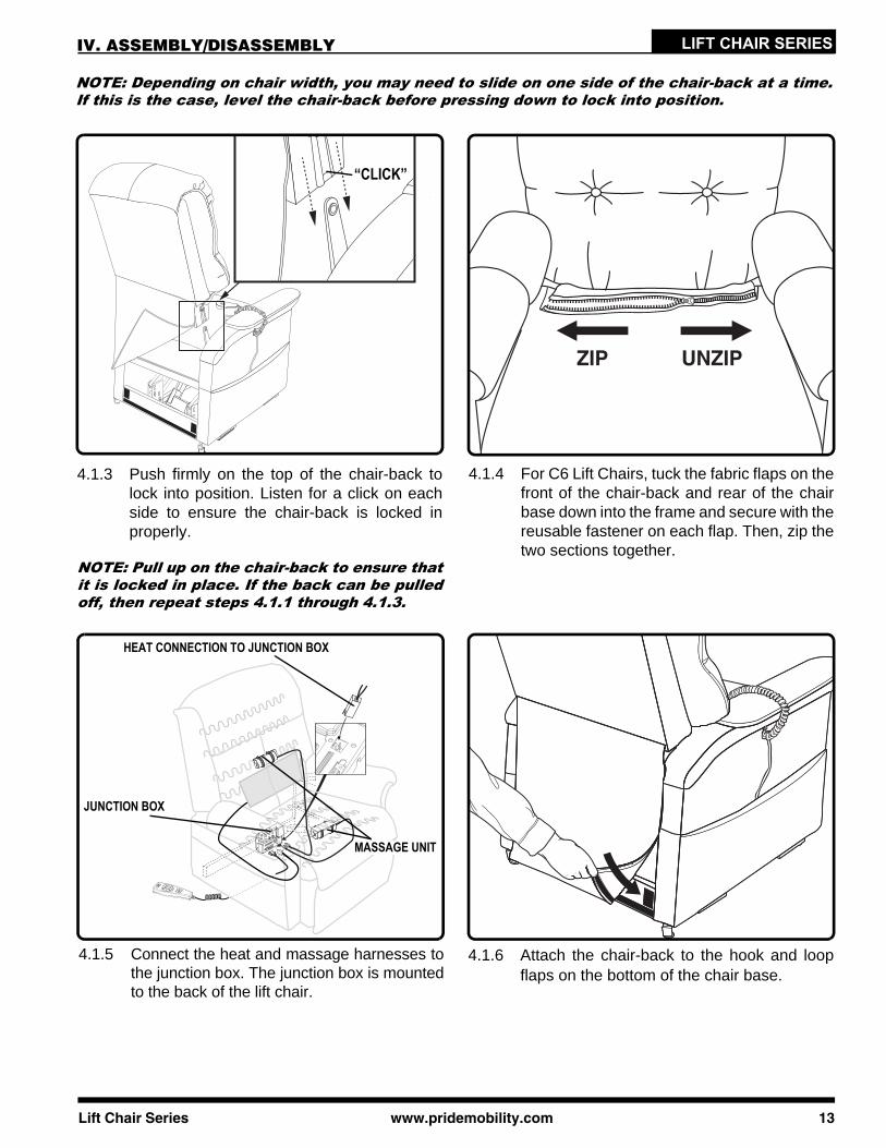
NOTE: Depending on chair width, you may need to slide on one side of the chair-back at a time.If this is the case, level the chair-back before pressing down to lock into position.
“CLICK”
4.1.3 Push firmly on the top of the chair-back tolock into position. Listen for a click on eachside to ensure the chair-back is locked inproperly.
NOTE: Pull up on the chair-back to ensure thatit is locked in place. If the back can be pulledoff, then repeat steps 4.1.1 through 4.1.3.
Lift Chair Series www.prid
4.1.5 Connect the heat and massage harnesses tothe junction box. The junction box is mountedto the back of the lift chair.
HEAT CONNECTION TO JUNCTION BOX
JUNCTION BOX
MASSAGE UNIT
4.1.4 For C6 Lift Chairs, tuck the fabric flaps on thefront of the chair-back and rear of the chairbase down into the frame and secure with thereusable fastener on each flap. Then, zip thetwo sections together.
4.1.6 Attach the chair-back to the hook and loopflaps on the bottom of the chair base.
emobility.com 13

LIFT CHAIR SERIES IV. ASSEMBLY/DISASSEMBLY
LIFT CHAIR PLACEMENTYour lift chair should be placed near a standard electrical outlet on dry, level ground where there is ampleroom to allow for proper operation. Pride recommends that you have the assistance of an attendant whenpositioning the lift chair to avoid the possibility of injury when lifting.
Follow these steps to position the lift chair in a safe manner:1. Place the back of the lift chair 76 cm (30 in.) from the nearest obstruction while the chair is in the seated
position. This measurement may vary depending on model.2. Adjust the leg levelers to stabilise the lift chair (Fig. 3.2).3. Install the batteries into the external transformer if applicable. Refer to “Battery Installation” for more
information.4. Position the external transformer on the floor in an open, well-ventilated area where it will not be an
obstruction, or if equipped, utilise the optional wall mount.5. Position the low voltage connection cable where it will not be pinched between the frame and the lift
mechanism.6. Connect the low voltage connection cable to the external transformer if it is not already connected.7. Plug the power lead directly into the electrical outlet. Do not use an extension lead!
NOTE: If you discover a problem at any point during the set-up and positioning of your lift chair,stop and contact your authorised Pride Dealer immediately. To avoid personal injury and/or prod-uct damage, do not plug the unit into the electrical outlet until the problem is corrected and donot attempt to fix electrical problems by yourself.
BATTERY INSTALLATIONYour lift chair may be equipped with a battery backup system that will activate during a power failure. The backupsystem is powered by two 9V batteries (not included) that need to be installed into the external transformer.
EXTERNAL TRANSFORMER(TOP AND BOTTOM VIEW)
BATTERY DOOR
POWER LEAD
Follow these steps to install the batteries:1. Unplug the external transformer power lead from
the electrical outlet.2. Open the marked battery door on the external
transformer.3. Install two 9V batteries into the external trans-
former (Fig. 4.2).4. Replace the battery door.
NOTE: Always make sure the external trans-former is equipped with two fresh 9V batteries,since the battery backup system does notrecharge itself. Fresh batteries are defined as9V alkaline batteries that are replaced everytime the battery backup system is activatedduring a power failure, or once a year if the bat-tery backup system has not been activated.
NOTE: If you unplug your lift chair for anextended period of time (more than one hour),remove the batteries from the external trans-former. The lift chair will draw power from thebatteries even when it is not in use.
14 www.pridemobility.com Lift Chair Series
Figure 4.2 Lift Chair Battery Backup Location

LIFT CHAIR SERIESIV. ASSEMBLY/DISASSEMBLY
LIFT CHAIR DISASSEMBLYThe back portion of KD Lift Chairs can be removed to make service and transport of the chair more convenient.
Follow these steps to disassemble the lift chair:
4.3.1 Remove the bottom of the back fabric fromthe hook and loop flaps on the chair base.
NOTE: If equipped with a heat and massageoption, be sure to disconnect the heat and mas-sage harnesses from the junction box.
Lift Chair Series www.prid
4.3.2 For C6 Lift Chairs, unzip the chair-back fromthe chair base, then disengage the reusablefastener securing the chair-back fabric to theframe.
4.3.3 Using a large flat-head screwdriver, lift theleft and right locking clips on the chair-backone side at a time to raise the back from theconnections on the chair base. As you lifteach locking clip, pull up on the chair-back tolift that side over the lock.
4.3.4 Lift the chair-back up and away from thechair base.
emobility.com 15

LIFT CHAIR SERIES IV. ASSEMBLY/DISASSEMBLY
FABRIC REMOVAL/INSTALLATIONThe fabric on some lift chairs can be removed to make cleaning and service of the chair more convenient. Ifyour chair is equipped with removable fabric, please see below.
Follow these steps to remove and install the lift chair fabric:
4.4.1 Disconnect the hand control from the quickrelease cable located in the lift chair sidepocket. Place the hand control in a safe loca-tion out of the way.
16 www.pridem
4.4.2 Push the quick release cable through the “V”cut hole in the side pocket of the lift chair.
4.4.3 Slide the left and right side arm covers off ofthe metal side arms.
4.4.4 For C6 Lift Chairs, unzip the chaise pad fromthe seat back cover.
obility.com Lift Chair Series

LIFT CHAIR SERIESIV. ASSEMBLY/DISASSEMBLY
4.4.5 Loosen the front portion of the chaise padfrom the footrest and remove the chaise padfrom the lift chair.
Lift Chair Series www.prid
4.4.6 Remove the footrest side covers.
NOTE: This feature does not apply to the C1Lift Chair.
4.4.7 Disengage the bottom flap of the seat backcover from the bottom seat rail.
4.4.8 Loosen the bottom seat back cover flapsfrom the bottom of the seat back.
emobility.com 17

LIFT CHAIR SERIES IV. ASSEMBLY/DISASSEMBLY
4.4.9 Remove the seat back cover.
18 www.pridem
4.4.10 Loosen the seat box cover from the left andright side of the seat box.
4.4.11 Remove the seat box cover.
NOTE: Follow the fabric removal steps in thereverse order to install the fabric componentsto the lift chair.
obility.com Lift Chair Series

LIFT CHAIR SERIESV. OPERATION
OPERATION PRECAUTIONSThere are certain precautions that should be taken during the operation of your lift chair. Read andfollow these precautions carefully in order to ensure safe lift chair operation and to prevent injuryand/or product damage.
Plug the power lead directly into the electrical outlet. Do not use an extension lead!Do not place anything (e.g., a drinking glass) on top of or near the external transformer.If the external transformer box or hand control requires cleaning, unplug the power lead from the electricaloutlet and use a clean, dry cloth or lightly dampened cloth. Allow ample drying time before plugging thepower lead back into the electrical outlet.Periodically check the hand control and all power leads for visible damage.Keep the hand control away from all heated surfaces.Ensure the hand control is out of the way before sitting in the chair.Keep children and pets away from all moving parts while operating the lift chair.Do not allow children to play on or operate the lift chair. Only the intended user should operate the lift chair.Keep the hand control locked or utilise the quick-disconnect feature when the lift chair is not in use toprevent unintended operation of the chair.Avoid pinch points, such as the lift and scissor mechanisms. Keep hands and feet clear of these areas.Always leave the lift chair in an upright and closed position when not in use.Do not sit or stand on the footrest.Do not “drop” into the lift chair when sitting if it is in a partially raised position.
PROHIBITED! Do not place objects under the lift chair. Make sure area is clear ofobstructions, including pets and small children during operation.
WARNING! Prevent the risk of electrical shock, fire, falls and/or being pinched.Follow all instructions and precautions provided.
WARNING! Prevent potential equipment damage! Do not place the externaltransformer under the lift chair.
WARNING! Do not cover the external transformer. Keep the transformer in an open,well-ventilated area free from foreign material/debris to ensure proper operation.
HAND CONTROL OPERATIONDepending on lift chair model, the hand control may be equipped with switches that control the movement of thechair-back, chair base and footrest (Fig. 5.1, 5.2 and 5.3).
WARNING! Do not lean on or apply downward force to the chair-back when the liftchair is in the fully reclined position. Doing so could cause the lift chair to tip,resulting in personal injury and/or product damage.
WARNING! Do not use the footrest as a seat, or for purposes outside its intendeduse. Doing so could cause instability in the lift chair and place undue stress on liftchair components, resulting in personal injury and/or product damage.
WARNING! Be sure to lock or disconnect the hand control when the lift chair is notin use.
Lift Chair Series www.pridemobility.com 19
LIFT CHAIR SERIES V. OPERATION
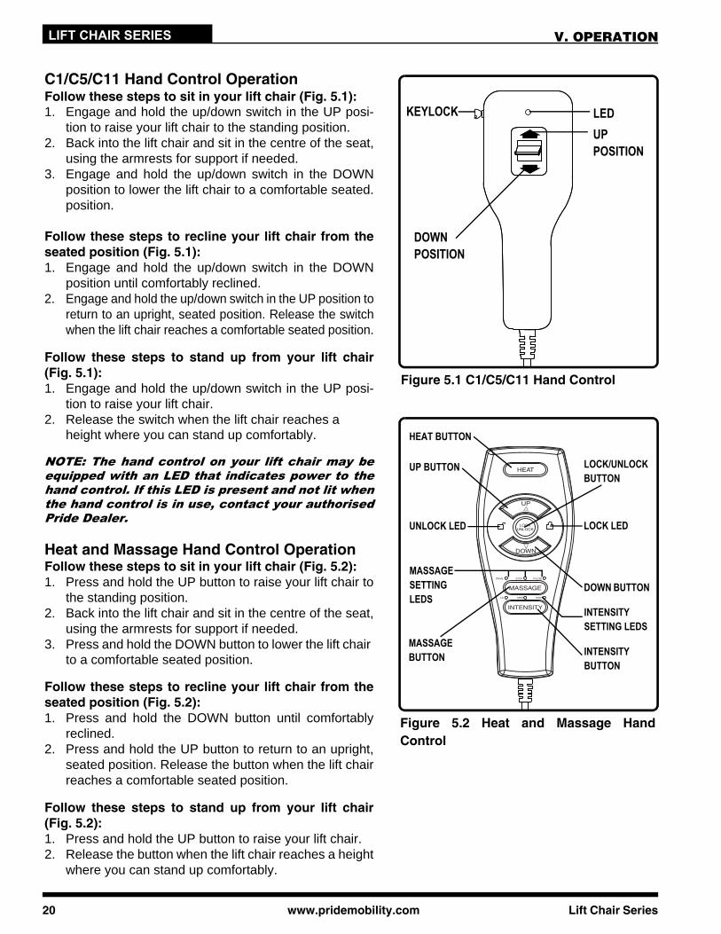
C1/C5/C11 Hand Control OperationFollow these steps to sit in your lift chair (Fig. 5.1):1. Engage and hold the up/down switch in the UP posi-
tion to raise your lift chair to the standing position.2. Back into the lift chair and sit in the centre of the seat,
using the armrests for support if needed.3. Engage and hold the up/down switch in the DOWN
position to lower the lift chair to a comfortable seated.position.
Follow these steps to recline your lift chair from theseated position (Fig. 5.1):1. Engage and hold the up/down switch in the DOWN
position until comfortably reclined.2. Engage and hold the up/down switch in the UP position to
return to an upright, seated position. Release the switchwhen the lift chair reaches a comfortable seated position.
Follow these steps to stand up from your lift chair(Fig. 5.1):1. Engage and hold the up/down switch in the UP posi-
tion to raise your lift chair.2. Release the switch when the lift chair reaches a
height where you can stand up comfortably.
NOTE: The hand control on your lift chair may beequipped with an LED that indicates power to thehand control. If this LED is present and not lit whenthe hand control is in use, contact your authorisedPride Dealer.
Figure 5.2 Heat and Massage HandControl
HEAT BUTTON
UP BUTTON
UNLOCK LED
LOCK/UNLOCK BUTTON
LOCK LED
DOWN BUTTONMASSAGE SETTING LEDS
MASSAGE BUTTON INTENSITY
BUTTON
INTENSITY SETTING LEDS
Figure 5.1 C1/C5/C11 Hand Control
UP POSITION
DOWN POSITION
KEYLOCK LED
Heat and Massage Hand Control OperationFollow these steps to sit in your lift chair (Fig. 5.2):1. Press and hold the UP button to raise your lift chair to
the standing position.2. Back into the lift chair and sit in the centre of the seat,
using the armrests for support if needed.3. Press and hold the DOWN button to lower the lift chair
to a comfortable seated position.
Follow these steps to recline your lift chair from theseated position (Fig. 5.2):1. Press and hold the DOWN button until comfortably
reclined.2. Press and hold the UP button to return to an upright,
seated position. Release the button when the lift chairreaches a comfortable seated position.
Follow these steps to stand up from your lift chair(Fig. 5.2):1. Press and hold the UP button to raise your lift chair.2. Release the button when the lift chair reaches a height
where you can stand up comfortably.
20 www.pridemobility.com Lift Chair Series

Lift Chair Series www.pridemobility.com 21
LIFT CHAIR SERIESV. OPERATION
Follow these steps to activate/deactivate the lock feature (Fig. 5.2):1. Press and hold the LOCK button for approximately 3 seconds to lock the hand control. The red LED to the
right of the button will light up to indicate the hand control has been locked.2. Press and hold the LOCK button for approximately 6 seconds to unlock the hand control. The green LED
to the left of the button will light up to indicate the hand control has been unlocked.
Follow these steps to operate the heat function (Fig. 5.2):1. Press the HEAT button once to activate the heat function. The heat function will shut off automatically after
20 minutes of continuous use.2. Press the HEAT button again to turn off the heat function.
Follow these steps to operate the massage option (Fig. 5.2):1. Press the MASSAGE button once to activate the massage function. This will automatically set the mas-
sage to the wave setting.2. Press the MASSAGE button again to go to the next of three available massage settings: wave, steady or
pulse. Each press of the button will take you to the next setting. Each setting is indicated by a colouredLED.
3. Press and hold the MASSAGE button for approximately 2 seconds to shut off the massage function,otherwise this function will shut off automatically after 20 minutes of continuous use.
Follow these steps to adjust the intensity of the massage function (Fig. 5.2):1. Press the INTENSITY button once to set the massage option to low.2. Press the INTENSITY button again to set the massage option to the next of three available settings: low,
medium or high. Each press of the button will take you to the next setting. Each setting is indicated by acoloured LED.
NOTE: All heat units are designed with an auto-shutoff mechanism that turns off the heat after 20minutes of use. Pride recommends that the heat and massage units not be used for more than 20minutes at a time. However, you should consult your physician about how often you should usethe heat and massage options on your lift chair.
Figure 5.3 C6 Hand Control
UP POSITION
DOWN POSITION
INHIBIT SWITCH
KEYLOCK
C6 Hand Control OperationFollow these steps to sit in your lift chair (Fig. 5.3):1. Slide the inhibit switch to the left. 2. Engage and hold the up/down switch in the UP position
to raise your lift chair from the seated position to the standing position.
3. Back into the lift chair and sit in the centre of the seat, using the armrests for support if needed.
4. Engage and hold the up/down switch in the DOWN position to lower the lift chair to a comfortable seated position.
Follow these steps to recline your lift chair from theseated position (Fig. 5.3):1. Slide the inhibit switch to the right.2. Engage and hold the up/down switch in the DOWN
position until comfortably reclined.3. Engage and hold the up/down switch in the UP position
to return to an upright, seated position. Release theswitch when the lift chair reaches a comfortable seatedposition.

22 www.pridemobility.com Lift Chair Series
LIFT CHAIR SERIES V. OPERATION
Follow these steps to raise or lower the footrest while in the seated or reclined position (Fig. 5.3):1. Slide the inhibit switch to the left.2. Engage and hold the up/down switch in the DOWN position until the footrest reaches a comfortable
height.3. Engage and hold the up/down switch in the UP position to lower the footrest.
Follow these steps to stand up from your lift chair from the seated position (Fig. 5.3):1. Slide the inhibit switch to the left.2. Engage and hold the up/down switch in the UP position to raise your lift chair.3. Release the switch when the lift chair reaches a height where you can stand up comfortably.
KeylockYour hand control may be equipped with a keylock feature. The keylock feature is intended to disable allfunctions of the hand control to prevent unintended movement when the lift chair is occupied, but stationary,as well as when the lift chair is left unattended. The key should only be inserted into the hand control whenthe position of the lift chair needs to be adjusted by the user.
Follow these steps to operate the keylock:1. Remove the key from the side of the hand control to disable all functions of the hand control. 2. Reinsert the key to restore hand control function.
WARNING! Prevent unintended movement and/or injury! Remove the key to lockthe hand control once the lift chair is positioned to the desired setting by the userand any time the lift chair is left unattended.
NOTE: As an added safety measure, Pride recommends that you utilise the quick disconnect toremove the hand control from the lift chair and store the hand control out of the reach of chil-dren when not in use.

Lift Chair Series www.pridemobility.com 23
LIFT CHAIR SERIESVI. TROUBLESHOOTING
Your Pride Lift Chair is a state-of-the-art product designed to enhance your mobility. Your lift chairshould bring you years of trouble-free service, however, it may require occasional troubleshoot-ing. The following troubleshooting tips and FAQs should summarise what you need to know aboutyour lift chair. If at any time you do not feel comfortable performing the troubleshooting steps listedin this manual, contact your authorised Pride Dealer for service. Please have the model number,serial number and nature of the problem when calling.
FREQUENTLY ASKED QUESTIONS
What if my lift chair does not operate at all?Ensure the external transformer is plugged into a properly wired electrical outlet.Check the circuit breaker box connected to the electrical outlet to ensure the outlet is receiving power.Ensure the low voltage connection cable is plugged into the external transformer.Ensure that all cables are connected properly.
What if my lift chair operates in one direction only?Check the up and down buttons or toggle switch on the hand control to make sure they do not stick. Ifthe buttons or switch are sticking in either position, the hand control may need to be replaced.Contact your authorised Pride Dealer for further assistance.
What if my lift chair stops during a lifting cycle?Your lift chair is equipped with an internal thermal shutoff switch located inside the external transformerthat prevents the motor control box from overheating. If the thermal shutoff activates, allow the lift chairto remain in a stationary position for 10 minutes to allow the motor to cool, then resume normal operation.If you notice the motors overheating frequently, contact your authorised Pride Dealer.There may have been a power failure and/or there are no batteries in the external transformer or thebatteries have no charge. Always make sure there are fresh 9V batteries in the external transformer ifequipped with battery backup.Check the circuit breaker box connected to the electrical oulet.
What if my lift chair is rocking from corner to corner after I position the chair?The floor may be uneven or the carpet may be affecting chair position. Adjust the leg levelers in the areawhere the chair is rocking. See III. “Your Lift Chair” for instructions on leveling your chair.
What if the heat and massage options on my lift chair do not function?Ensure the junction box is connected properly to the external transformer and that there is power to thetransformer. A green LED will light on the transformer to indicate power.Ensure the heat and massage units are connected properly to the junction box and that the junction boxis connected properly to the actuator, both at the rear of the lift chair. Ensure the hand control is connected properly to the junction box. If connected properly, the LEDs on thehand control will be lit. If any of the LEDs do not light, contact your authorised Pride Dealer for further assistance.
Where can I place the external transformer box?On the floor away from heat sources in an open, well-ventilated area where it will not be an obstruction.On the wall away from heat sources utilising the optional external transformer wall mount. Refer to“Appendix B.”

24 www.pridemobility.com Lift Chair Series
LIFT CHAIR SERIES VI. TROUBLESHOOTING
Where do I find the serial number on my lift chair?You can find the serial number in two locations—one is near the rear of the motor on the steel lift mechanism,and the second is attached to the frame below the scissor mechanisms. The model number for your lift chairis printed below the serial number bar code.
Who do I call for service?Contact your authorised Pride Dealer for service.

Lift Chair Series www.pridemobility.com 25
LIFT CHAIR SERIES
Your Pride Lift Chair will require routine maintenance checks. You can perform some of thesechecks, but others may require assistance from an authorised Pride Dealer. By following themaintenance checks in this section as scheduled, you can help ensure your lift chair gives youyears of trouble-free operation. If you have any questions regarding your lift chair’s care, contactyour authorised Pride Dealer.
FABRIC CAREInspect the fabric on a regular basis for any pulls, tears or gaps.Your lift chair fabric is made of 100% polyester and falls under cleaning code W. Frequent vacuuming andlight brushing to remove dust and grime is the recommended cleaning method for your lift chair. If spotcleaning is required, you should use the foam from water-based cleaning agents such as mild detergentor non-solvent upholstery shampoo. Apply the foam with a soft brush in a circular motion and vacuumwhen dry. Pretest a small area of the fabric with the cleaning agent before using this method. If your liftchair fabric is in an overall soiled condition, use a professional furniture cleaning service.
WARNING! Fabric should not be allowed to come in direct contact with any type ofheat source (e.g., a space heater or cigarette). Personal injury or fire damage mayoccur.
WARNING! Pride strongly recommends that you do not smoke cigarettes whileseated in or using your lift chair, although the lift chair has passed the necessarytesting requirements for cigarette smoking. You must adhere to the followingsafety guidelines if you decide to smoke cigarettes while seated in or using yourlift chair.
Do not leave lit cigarettes unattended.Keep ashtrays a safe distance from the lift chair.Always make sure cigarettes are completely extinguished before disposal.
NOTE: Do not use solvent-type cleaners to spot clean. Do not saturate the fabric. Prevent dam-age to the fabric; do not expose the lift chair to direct sunlight.
ELECTRONICS CAREInspect all wiring harnesses to make sure they are not damaged or frayed.If damage is present, unplug the lift chair and contact your authorised Pride Dealer for service.Keep all electronics free from moisture and temperature extremes. Pride Lift Chairs are intended forindoor use only!
WARNING! Even though the lift chair has passed the necessary testingrequirements for ingress of liquids, you should keep electrical connections awayfrom sources of dampness, including direct exposure to water or bodily fluids andincontinence. Check electrical components frequently for signs of corrosion andreplace as necessary.
DISPOSAL AND RECYCLINGYour lift chair must be disposed of according to applicable local and national statutory regulations. Contactyour local waste disposal agency or authorised Pride Dealer for information on proper disposal of lift chairpackaging, metal frame components, fabric, electronic components and batteries.
WARNING! Plastic bags are a suffocation hazard. Dispose of plastic bags properlyand do not allow children to play with them.
VII. CARE AND MAINTENANCE

26 www.pridemobility.com Lift Chair Series
LIFT CHAIR SERIES VIII. WARRANTY
TWO-YEAR LIMITED WARRANTYFor two (2) years from the date of purchase, Pride will repair or replace at our option to the originalpurchaser any of the following parts found upon examination by an authorised representative ofPride to be defective in material and/or workmanship:
Steel Frame Motor Hand Control Scissor Mechanisms Steel Lift Mechanism
NOTE: Pride reserves the right to replace only the part of the steel lift mechanism that may bedefective.
NOT COVERED UNDER WARRANTYThe following parts are classed as wear items, which may under normal wear and tear require replacing.These items are not therefore covered under warranty: all fabric. Warranty will also be refused if damage isdeemed to have been caused through misuse or accident for which Pride Mobility Products cannot bedeemed responsible.
NOTE: Pride Mobility Products provides parts only under warranty. Your Pride Dealer is respon-sible for labour and service. Please contact your Pride Dealer for information about these ser-vices and for any applicable charges.

Lift Chair Series www.pridemobility.com 27
LIFT CHAIR SERIESNOTES

28 www.pridemobility.com Lift Chair Series
LIFT CHAIR SERIES APPENDIX A
MANDATORY! Stay within the specified weight capacity of your lift chair.Exceeding the weight capacity voids your Pride Lift Chair warranty.
LIFT CHAIR WEIGHT CAPACITY Model Number Rated Weight Capacity
C1, C11 113 kg (250 lbs., 18 Stone)
C5 170 kg (375 lbs., 27 Stone)
C6 136 kg (300 lbs., 21 Stone)

Lift Chair Series www.pridemobility.com 29
LIFT CHAIR SERIES
EXTERNAL TRANSFORMER OPTIONAL WALL MOUNT DIAGRAMCut out this diagram (1:1 scale) and use to mark area of placement for the external transformer used with thehand control.
APPENDIX B
Drill

(This page intentionally left blank.)

SAFETY GUIDELINESLIFT CHAIR SERIES
NOTE: This owner’s manual is compiled from the latest specifications and product information avail-able at the time of publication. We reserve the right to make changes as they become necessary. Anychanges to our products may cause slight variations between the illustrations and explanations inthis manual and the product you have purchased. The latest/current version of this manual is avail-able on our website.
The symbols below are used throughout this owner's manual and on the product to identify warnings andimportant information. It is very important for you to read them and understand them completely.
WARNING! Indicates a potentially hazardous condition/situation. Failure to followdesignated procedures can cause either personal injury, component damage ormalfunction. On the product, this icon is represented as a black symbol on a yellowtriangle with a black border.
MANDATORY! These actions should be performed as specified. Failure to performmandatory actions can cause personal injury and/or equipment damage. On theproduct, this icon is represented as a white symbol on a blue dot with a whiteborder.
PROHIBITED! These actions are prohibited. These actions should not be performedat any time or in any circumstances. Performing a prohibited action can causepersonal injury and/or equipment damage. On the product, this icon is representedas a black symbol with a red circle and red slash.
Copyright © 2010Pride Mobility Products Ltd.INFMANU3652/Rev E/June 2010
Please fill out the following information for quick reference:
088 609 661
Pride Dealer:
Address:
Phone Number:
Purchase Date: Serial Number:

®
®
LIFT CHAIR
*INFMANU3652*
SERIES
Pride Mobility Products Ltd.32 Wedgwood Road
Bicester, Oxon OX26 4ULUK
Pride Mobility Products Australia Pty. Ltd.21 Healey Road
Dandenong, 3175Victoria, Australia
www.pridemobility.com
Including Model: C1, C5, C6 and C11