Embed Size (px)
Citation preview

UG154: EFM32 Pearl Gecko Starter KitUser's Guide
The SLSTK3401A Starter Kit is an excellent starting point to getfamiliar with the EFM32™ Pearl Gecko Microcontroller.The Starter Kit contains sensors and peripherals demonstrating some of the PearlGecko's many capabilities. The kit provides all necessary tools for developing an EFM32Pearl Gecko application.
TARGET DEVICE
• EFM32 Pearl Gecko Microcontroller(EFM32PG1B200F256GM48)
• CPU: 32-bit ARM® Cortex-M4® with FPU• Memory: 256 kB flash and 32 kB RAM
KIT FEATURES
• USB connectivity• Advanced Energy Monitor• SEGGER J-Link on-board debugger• Debug Multiplexer supporting external
hardware as well as on-board board MCU• Silicon Labs' Si7021 Relative Humidity and
Temperature sensor• Ultra low power 128x128 pixel Memory
LCD• User LEDs / Pushbuttons• 20-pin 2.54 mm header for expansion
boards• Breakout pads for direct access to I/O pins• Power sources includes USB and CR2032
coin cell battery.
SOFTWARE SUPPORT
• Simplicity Studio™• Energy Profiler
silabs.com | Smart. Connected. Energy-friendly. Rev. 1.01

1. Introduction
1.1 Description
The SLSTK3401A is an excellent starting point to get familiar with the EFM32 Pearl Gecko Microcontrollers. The kit contains sensorsand peripherals demonstrating some of the MCU's many capabilities. The kit can also serve as a starting point for application develop-ment.
In additon to supporting application development on the starter kit itself, the board is also a fully featured debugger and energy monitor-ing tool that can be used with external applications.
1.2 Features
• EFM32PG1B200F256GM48 MCU with 256 kB Flash and 32 kB RAM.• Advanced Energy Monitoring system for precise current tracking.• Integrated Segger J-Link USB debugger/emulator with the possiblity to debug external Silicon Labs devices.• 20 pin expansion header.• Breakout pads for easy access to I/O pins.• Power sources including USB and CR2032 battery.• Silicon Labs Si7021 Relative Humidity and Temperature Sensor• Ultra low power 128x128 pixel Memory-LCD• 2 push buttons and 2 LEDs connected to EFM32 for user interaction.• Crystals for LFXO and HFXO: 32.768 kHz and 40.000 MHz.
1.3 Getting Started
Hardware
To set up the hardware for the SLSTK3401A kit:1. Provide power to the board by connecting the DBG USB connector to the PC using the provided mini-USB cable.2. Ensure that the power selector switch is in the AEM position.
Software
The first step to get started with your new SLSTK3401A is to go to
http://www.silabs.com/simplicity
The Simplicity Studio software package contains all the tools, drivers, software examples and documentation needed to use the EFM32Pearl Gecko Starter Kit. The board comes pre-loaded with a default application, Blinky, to play with while the software downloads.
After downloading the latest version of Simplicity Studio and installing using the [Full] or [EFM32] options:
1. Click the [Refresh detected hardware] button and select the EFM32 Pearl Gecko Starter Kit under [Detected Hardware].2. Click the [Demos] tile under [Tools] to load the available demos.3. Click the Blinky demo and click [Start] to download and run the demo.
Additional demos showcasing the various features of the Pearl Gecko are also available under the same tile in Simplicity Studio.
UG154: EFM32 Pearl Gecko Starter Kit User's GuideIntroduction
silabs.com | Smart. Connected. Energy-friendly. Rev. 1.01 | 1
2. Kit Block Diagram
An overview of the EFM32 Pearl Gecko Starter Kit is shown in the figure below.
EFM32 Pearl Gecko MCU
128 x 128 pixelMemory LCD
SP
I
Si7021
Temperature& Humidity
Sensor
EXP HeaderGPIO
I2C
GP
IO
User Buttons& LEDs Capacitive Touchpads
AC
MP
BoardController
USB Mini-BConnector
DEBUG
UART
Figure 2.1. Kit Block Diagram
UG154: EFM32 Pearl Gecko Starter Kit User's GuideKit Block Diagram
silabs.com | Smart. Connected. Energy-friendly. Rev. 1.01 | 2
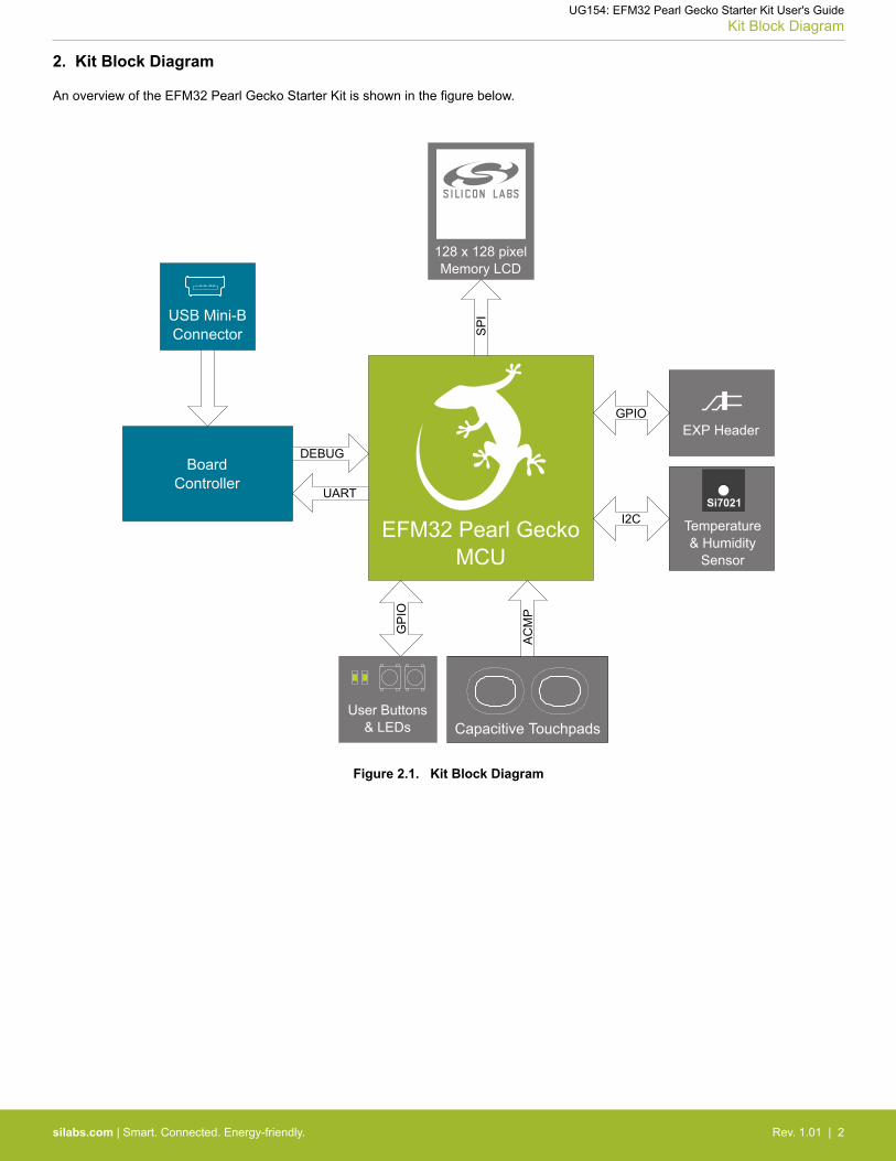
3. Kit Hardware Layout
The layout of the EFM32 Pearl Gecko Starter Kit is shown below.
Kit "Debug" USBConnector
CR2032Battery Holder
128x128 PixelMemory LCD
Debug Connector
Simplicity Connector
Relative Humidity &Temperature Sensor
EFM32 PG MCU
Expansion Header
EFM32 Reset Button
Capacitive Touch PadsUser LEDsUser PushButtonsPower Source Select
Figure 3.1. SLSTK3401A Hardware Layout
UG154: EFM32 Pearl Gecko Starter Kit User's GuideKit Hardware Layout
silabs.com | Smart. Connected. Energy-friendly. Rev. 1.01 | 3
4. Connectors
4.1 Breakout Pads
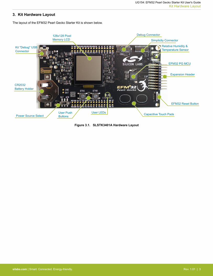
Most of the EFM32's GPIO pins are available on two pin header rows at the top and bottom edges of the board. These have a standard2.54 mm pitch, and pin headers can be soldered in if required. In addition to the I/O pins, connections to the different power rails andground are also provided. Note that some of the pins are used for kit peripherals or features, and may not be available for a customapplication without trade-offs.
The figure below shows the pinout of these "breakout pads", as well as the pinout of the "Expansion Header" situated on the right-handside of the board. The expansion header is further explained in the next section. The breakout pad connections are also printed in silkscreen next to each pin for easy reference.
GN
DVM
CU
NC
NC
NC
NC
GN
D
NC
NC
PC11
PC10
PC9
PC8
PC7
PC6
3V3
GN
DVM
CU
NC
NC
PB13NC
GN
D
NC
NC
PA5
PA4
PA3
PA2
PA1
PA0
3V3
J101
J102
GN
D5V N
CN
CN
CN
C
GN
D
NC
PD15
PD14
PD13
PD12
PD11
PD10
PD9
3V3
GN
D5V NC
NC
NC
NC
GN
D
PF7
PF6
PF5
PF4
PF3
PF2
PF1
PF0
3V3
PA2PA3PA4PD10
GND
PD11PB13PC11
5V
PC6PC7PC8PC9PA0PA1
PC10
VMCU
3V3 Board ID SDABoard ID SCL
EXP Header
DebugConnector
SimplicityConnector
Figure 4.1. Breakout Pads and Expansion Header
The table below shows the connections of each pin of the breakout pads. They also show which kit peripherals or features are connec-ted to the different pins.
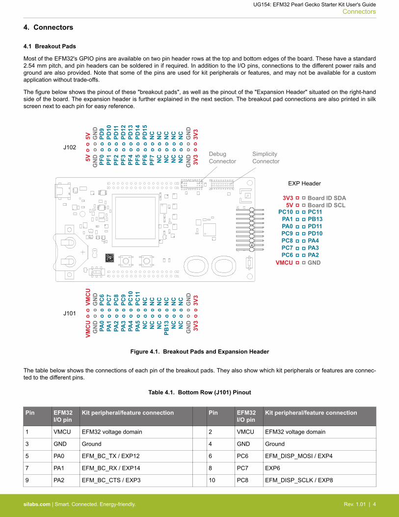
Table 4.1. Bottom Row (J101) Pinout
Pin EFM32I/O pin
Kit peripheral/feature connection Pin EFM32I/O pin
Kit peripheral/feature connection
1 VMCU EFM32 voltage domain 2 VMCU EFM32 voltage domain
3 GND Ground 4 GND Ground
5 PA0 EFM_BC_TX / EXP12 6 PC6 EFM_DISP_MOSI / EXP4
7 PA1 EFM_BC_RX / EXP14 8 PC7 EXP6
9 PA2 EFM_BC_CTS / EXP3 10 PC8 EFM_DISP_SCLK / EXP8
UG154: EFM32 Pearl Gecko Starter Kit User's GuideConnectors
silabs.com | Smart. Connected. Energy-friendly. Rev. 1.01 | 4
Pin EFM32I/O pin
Kit peripheral/feature connection Pin EFM32I/O pin
Kit peripheral/feature connection
11 PA3 EFM_BC_RTS / EXP5 12 PC9 EXP10
13 PA4 EXP7 14 PC10 SENSOR_I2C_SDA / EXP16
15 PA5 EFM_BC_EN 16 PC11 SENSOR_I2C_SCL / EXP15
17 - Not connected 18 - Not connected
19 - Not connected 20 - Not connected
21 - Not connected 22 - Not connected
23 PB13 EXP13 24 - Not connected
25 - Not connected 26 - Not connected
27 - Not connected 28 - Not connected
29 GND Ground 30 GND Ground
31 3V3 Board controller supply 32 3V3 Board controller supply
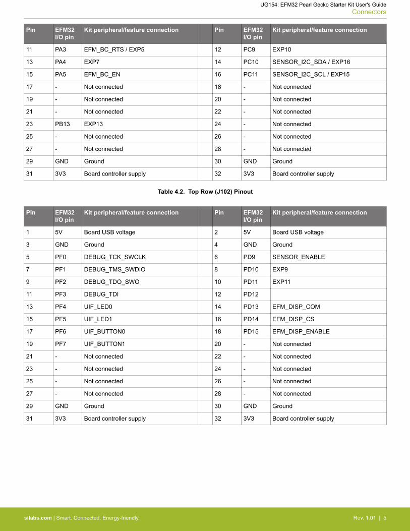
Table 4.2. Top Row (J102) Pinout
Pin EFM32I/O pin
Kit peripheral/feature connection Pin EFM32I/O pin
Kit peripheral/feature connection
1 5V Board USB voltage 2 5V Board USB voltage
3 GND Ground 4 GND Ground
5 PF0 DEBUG_TCK_SWCLK 6 PD9 SENSOR_ENABLE
7 PF1 DEBUG_TMS_SWDIO 8 PD10 EXP9
9 PF2 DEBUG_TDO_SWO 10 PD11 EXP11
11 PF3 DEBUG_TDI 12 PD12
13 PF4 UIF_LED0 14 PD13 EFM_DISP_COM
15 PF5 UIF_LED1 16 PD14 EFM_DISP_CS
17 PF6 UIF_BUTTON0 18 PD15 EFM_DISP_ENABLE
19 PF7 UIF_BUTTON1 20 - Not connected
21 - Not connected 22 - Not connected
23 - Not connected 24 - Not connected
25 - Not connected 26 - Not connected
27 - Not connected 28 - Not connected
29 GND Ground 30 GND Ground
31 3V3 Board controller supply 32 3V3 Board controller supply
UG154: EFM32 Pearl Gecko Starter Kit User's GuideConnectors
silabs.com | Smart. Connected. Energy-friendly. Rev. 1.01 | 5

4.2 Expansion Header
On the right hand side of the board an angled 20 pin expansion header is provided to allow connection of peripherals or plugin boards.The connector contains a number of I/O pins that can be used with most of the EFM32 Pearl Gecko's features. Additionally, the VMCU,3V3 and 5V power rails are also exported.
The connector follows a standard which ensures that commonly used peripherals such as an SPI, a UART and an I2C bus are availableon fixed locations in the connector. The rest of the pins are used for general purpose I/O. This allows the definition of expansion boardsthat can plug into a number of different Silicon Labs starter kits.
The figure below shows the pin assignment of the expansion header for the EFM32 Pearl Gecko Starter Kit. Because of limitations inthe number of available GPIO pins, some of the expansion header pins are shared with kit features.
124
86
10
35
97
12131411
15161718
20 19
VMCUPC6PC7PC8PC9PA0PA1
PC105V
3V3
GNDPA2PA3PA4PD10PD11PB13PC11
Board ID SDABoard ID SCL
Reserved (Board Identification)
TARGET I/O Pin
Figure 4.2. Expansion Header
Table 4.3. EXP Header Pinout
Pin Connection EXP Header function Primary function Shared feature
20 3V3 Board controller supply
18 5V Board USB voltage
16 PC10 I2C_SDA I2C0_SDA #15 SENSOR_I2C_SDA
14 PA1 UART_RX USART0_RX #0 VCOM_RX
12 PA0 UART_TX USART0_TX #0 VCOM_TX
10 PC9 SPI_CS USART1_CS #11
8 PC8 SPI_SCLK USART1_CLK #11 DISP_SCLK
6 PC7 SPI_MISO USART1_RX #11
4 PC6 SPI_MOSI USART1_TX #11 DISP_MOSI
2 VMCU EFM32 voltage domain, included in AEM measurements.
19 BOARD_ID_SDA Connected to Board Controller for identification of add-on boards.
17 BOARD_ID_SCL Connected to Board Controller for identification of add-on boards.
15 PC11 I2C_SCL I2C0_SCL #15 SENSOR_I2C_SCL
13 PB13 GPIO
11 PD11 GPIO
UG154: EFM32 Pearl Gecko Starter Kit User's GuideConnectors
silabs.com | Smart. Connected. Energy-friendly. Rev. 1.01 | 6
Pin Connection EXP Header function Primary function Shared feature
9 PD10 GPIO
7 PA4 GPIO
5 PA3 GPIO VCOM_RTS
3 PA2 GPIO VCOM_CTS
1 GND Ground
4.3 Debug Connector (DBG)
The Debug Connector serves a dual purpose. Based on the "debug mode", which can be set up using Simplicity Studio. In the "DebugIN" mode this connector allows an external debug emulator to be used with the on-board EFM32. In the "Debug OUT" mode this con-nector allows the kit to be used as a debugger towards an external target. In the "Debug MCU" (default) mode this connector is isolatedfrom the debug interface of both the Board Controller and the on-board target device.
Because this connector is automatically switched to support the different operating modes, it is only available when the Board Controlleris powered (J-Link USB cable connected). If debug access to the target device is required when the Board Controller is unpowered, thisshould be done by connecting directly to the appropriate breakout pins.
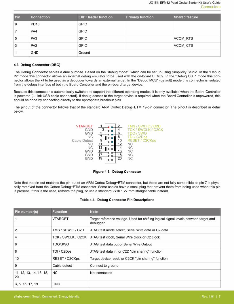
The pinout of the connector follows that of the standard ARM Cortex Debug+ETM 19-pin connector. The pinout is described in detailbelow.
1 24
86
10
35
912
13 1411
15 1617 18
2019
TMS / SWDIO / C2DTCK / SWCLK / C2CKTDO / SWOTDI / C2DpsRESET / C2CKps
GNDNC
NC
GND
GNDGND
7
GNDVTARGET
Cable Detect
NC
NCNCNCNCNC
Figure 4.3. Debug Connector
Note that the pin-out matches the pin-out of an ARM Cortex Debug+ETM connector, but these are not fully compatible as pin 7 is physi-cally removed from the Cortex Debug+ETM connector. Some cables have a small plug that prevent them from being used when this pinis present. If this is the case, remove the plug, or use a standard 2x10 1.27 mm straight cable instead.
Table 4.4. Debug Connector Pin Descriptions
Pin number(s) Function Note
1 VTARGET Target reference voltage. Used for shifting logical signal levels between target anddebugger.
2 TMS / SDWIO / C2D JTAG test mode select, Serial Wire data or C2 data
4 TCK / SWCLK / C2CK JTAG test clock, Serial Wire clock or C2 clock
6 TDO/SWO JTAG test data out or Serial Wire Output
8 TDI / C2Dps JTAG test data in, or C2D "pin sharing" function
10 RESET / C2CKps Target device reset, or C2CK "pin sharing" function
9 Cable detect Connect to ground
11, 12, 13, 14, 16, 18,20
NC Not connected
3, 5, 15, 17, 19 GND
UG154: EFM32 Pearl Gecko Starter Kit User's GuideConnectors
silabs.com | Smart. Connected. Energy-friendly. Rev. 1.01 | 7

4.4 Simplicity Connector
The Simplicity Connector featured on the Starter Kit enables advanced debugging features such as the AEM and the Virtual COM portto be used towards an external target. The pinout is illustrated in the figure below.
VMCU 133V355V
15GND13GND11GND9GND7GND
17Board ID SCL19Board ID SDA
2 Virtual COM TX / MOSI4 Virtual COM RX / MISO6 Virtual COM CTS / SCLK8 Virtual COM RTS / CS10 NC12 NC14 NC16 NC18 NC20 NC
Figure 4.4. Simplicity Connector
Note: Current drawn from the VMCU voltage pin is included in the AEM measurements, while the 3V3 and 5V voltage pins are not. Tomonitor the current consumption of an external target with the AEM, put the on-board MCU in its lowest energy mode to minimize itsimpact on the measurements.
Table 4.5. Simplicity Connector Pin Descriptions
Pin number(s) Function Description
1 VMCU 3.3 V power rail, monitored by the AEM
3 3V3 3.3 V power rail
5 5V 5 V power rail
2 VCOM_TX_MOSI Virtual COM Tx/MOSI
4 VCOM_RX_MISO Virtual COM Rx/MISO
6 VCOM_CTS_SCLK Virtual COM CTS/SCLK
8 VCOM_RTS_CS Virtual COM RTS/CS
17 EXT_ID_SCL Board ID SCL
19 EXT_ID_SDA Board ID SDA
10, 12, 14, 16, 18, 20 NC Not connected
7, 9, 11, 13, 15 GND Ground
UG154: EFM32 Pearl Gecko Starter Kit User's GuideConnectors
silabs.com | Smart. Connected. Energy-friendly. Rev. 1.01 | 8
5. Power Supply and Reset
5.1 MCU Power Selection
The EFM32 on the Starter Kit can be powered by one of these sources:
• The debug USB cable; or• a 3 V coin cell battery.
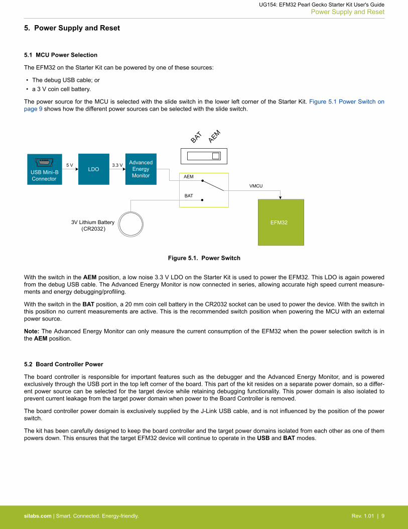
The power source for the MCU is selected with the slide switch in the lower left corner of the Starter Kit. Figure 5.1 Power Switch onpage 9 shows how the different power sources can be selected with the slide switch.
3.3 V
VMCU
AEM
BAT
USB Mini-BConnector
Advanced Energy Monitor
5 V
3V Lithium Battery (CR2032)
EFM32
BATAEM
LDO
Figure 5.1. Power Switch
With the switch in the AEM position, a low noise 3.3 V LDO on the Starter Kit is used to power the EFM32. This LDO is again poweredfrom the debug USB cable. The Advanced Energy Monitor is now connected in series, allowing accurate high speed current measure-ments and energy debugging/profiling.
With the switch in the BAT position, a 20 mm coin cell battery in the CR2032 socket can be used to power the device. With the switch inthis position no current measurements are active. This is the recommended switch position when powering the MCU with an externalpower source.
Note: The Advanced Energy Monitor can only measure the current consumption of the EFM32 when the power selection switch is inthe AEM position.
5.2 Board Controller Power
The board controller is responsible for important features such as the debugger and the Advanced Energy Monitor, and is poweredexclusively through the USB port in the top left corner of the board. This part of the kit resides on a separate power domain, so a differ-ent power source can be selected for the target device while retaining debugging functionality. This power domain is also isolated toprevent current leakage from the target power domain when power to the Board Controller is removed.
The board controller power domain is exclusively supplied by the J-Link USB cable, and is not influenced by the position of the powerswitch.
The kit has been carefully designed to keep the board controller and the target power domains isolated from each other as one of thempowers down. This ensures that the target EFM32 device will continue to operate in the USB and BAT modes.
UG154: EFM32 Pearl Gecko Starter Kit User's GuidePower Supply and Reset
silabs.com | Smart. Connected. Energy-friendly. Rev. 1.01 | 9

5.3 EFM32 Reset
The EFM32 MCU can be reset by a few different sources:• A user pressing the RESET button.• The on-board debugger pulling the #RESET pin low.• An external debugger pulling the #RESET pin low.
In addition to the reset sources mentioned above, the Board Controller will also issue a reset to the EFM32 when booting up. Thismeans that removing power to the Board Controller (plugging out the J-Link USB cable) will not generate a reset, but plugging the cableback in will, as the Board Controller boots up.
UG154: EFM32 Pearl Gecko Starter Kit User's GuidePower Supply and Reset
silabs.com | Smart. Connected. Energy-friendly. Rev. 1.01 | 10

6. Peripherals
The starter kit has a set of peripherals that showcase some of the features of the EFM32.
Be aware that most EFM32 I/O routed to peripherals are also routed to the breakout pads. This must be taken into consideration whenusing the breakout pads for your application.
6.1 Push Buttons and LEDs
The kit has two user push buttons marked PB0 and PB1. They are connected directly to the EFM32, and are debounced by RC filterswith a time constant of 1 ms. The buttons are connected to pins PF6 and PF7.
The kit also features two yellow LEDs marked LED0 and LED1, that are controlled by GPIO pins on the EFM32. The LEDs are connec-ted to pins PF4 and PF5 in an active-high configuration.
PF5 (GPIO)User Buttons
& LEDs
UIF_LED0
UIF_LED1
UIF_PB0
UIF_PB1PF6 (GPIO)
PF7 (GPIO)
PF4 (GPIO)
EFM32
Figure 6.1. Buttons and LEDs
UG154: EFM32 Pearl Gecko Starter Kit User's GuidePeripherals
silabs.com | Smart. Connected. Energy-friendly. Rev. 1.01 | 11

6.2 Memory LCD-TFT Display
A 1.28-inch SHARP Memory LCD-TFT has been added to the board to enable interactive applications to be developed. The display hasa high resolution of 128 by 128 pixels, and consumes very little power. It is a reflective monochrome display, so each pixel can only belight or dark, and no backlight is needed in normal daylight conditions. Data sent to the display is stored in the pixels on the glass, whichmeans no continous refreshing is required to maintain a static image.
The display interface consists of an SPI-compatible serial interface and some extra control signals. Pixels are not individually addressa-ble, instead data is sent to the display one line (128 bits) at a time.
The Memory LCD-TFT display is shared with the kit Board Controller, allowing the Board Controller application to display useful infor-mation when the user application is not using the display. The user application always controls ownership of the display with theEFM_DISP_ENABLE line:• 0: The Board Controller has control of the display• 1: The user application (EFM32) has control of the display
Power to the display is sourced from the target application power domain when the EFM32 controls the display, and from the BoardController's power domain when the EFM_DISP_ENABLE line is low. Data is clocked in on EFM_DISP_MOSI when EFM_DISP_CS ishigh, and the clock is sent on EFM_DISP_SCLK. The maximum supported clock speed is 1.1 MHz.
EFM_DISP_COM is the "COM Inversion" line. It must be pulsed periodically to prevent static build-up in the display itself. Please referto the display application information for details on driving the display:
http://www.sharpmemorylcd.com/1-28-inch-memory-lcd.html
PC8 (US1_CLK#11)
PC6 (US1_TX#11)
PD14 (GPIO)
PD13 (GPIO)
PD15 (GPIO)
EFM32
0: Board Controller controls display1: EFM32 controls display
Figure 6.2. 128x128 pixel Memory LCD
UG154: EFM32 Pearl Gecko Starter Kit User's GuidePeripherals
silabs.com | Smart. Connected. Energy-friendly. Rev. 1.01 | 12

6.3 Capacitive Touch Pads
Two touch pads, T1 and T2, utilizing the capacitive touch capability of the EFM32 are available. They are located on the lower right sideof the board, beneath the EFM32. The pads are connected to PB11 and PB12.
PB11 (ACMP0 BUS 3Y/4X CH27)
PB12 (ACMP0 BUS 3X/4Y CH28)
UIF_TOUCH0
UIF_TOUCH1
EFM32
Capacitive Touch Pads
Figure 6.3. Touch Pads
The capacitive touch pads work by sensing changes in the capacitance of the pads when touched by a human finger. Sensing thechanges in capacitance is done by setting up the touch pad as part of an RC relaxation oscillator using the EFM32's analog compara-tor, and then counting the number of oscillations during a fixed period of time.
6.4 Si7021 Relative Humidity and Temperature Sensor
The Si7021 I2C relative humidity and temperature sensor is a monolithic CMOS IC integrating humidity and temperature sensor ele-ments, an analog-to-digital converter, signal processing, calibration data, and an I2C Interface. The patented use of industry-standard,low-K polymeric dielectrics for sensing humidity enables the construction of low-power, monolithic CMOS Sensor ICs with low drift andhysteresis, and excellent long term stability.
The humidity and temperature sensors are factory-calibrated and the calibration data is stored in the on-chip non-volatile memory. Thisensures that the sensors are fully interchangeable, with no recalibration or software changes required.
The Si7021 is available in a 3x3 mm DFN package and is reflow solderable. It can be used as a hardware- and software-compatibledrop-in upgrade for existing RH/ temperature sensors in 3x3 mm DFN-6 packages, featuring precision sensing over a wider range andlower power consumption. The optional factory-installed cover offers a low profile, convenient means of protecting the sensor duringassembly (e.g., reflow soldering) and throughout the life of the product, excluding liquids (hydrophobic/oleophobic) and particulates.
The Si7021 offers an accurate, low-power, factory-calibrated digital solution ideal for measuring humidity, dew-point, and temperature,in applications ranging from HVAC/R and asset tracking to industrial and consumer platforms.
The I2C bus used for the Si7021 is shared with the Expansion Header. The temperature sensor is normally isolated from the I2C line. Touse the sensor, PD9 must be set high. When enabled, the sensor's current consumption is included in the AEM measurements.
SENSOR_ENABLE0: I2C lines are isolated, sensor is not powered1: Sensor is powered and connected
PC11 (I2C0_SCL#15)
PC10 (I2C0_SDA#15)
PD9 (GPIO)
SENSOR_I2C_SDA
SENSOR_I2C_SCL
VMCU
VDD
SCL
SDA Temperature& Humidity
Sensor
EFM32
Si7021
Figure 6.4. Si7021 Relative Humidity and Temperature Sensor
Please refer to the Silicon Labs web pages for more information: http://www.silabs.com/humidity-sensors
UG154: EFM32 Pearl Gecko Starter Kit User's GuidePeripherals
silabs.com | Smart. Connected. Energy-friendly. Rev. 1.01 | 13

6.5 USB to UART Bridge
The board controller on the kit provides a virtual com port (CDC) interface when plugged into a computer. The target EFM32 can con-nect to this serial port interface and communicate directly with the host computer.
The interface is enabled by setting the EFM_BC_EN (PA5) line high, and the UART peripheral used is USART0, Location 0 (TX pinPA0, RX pin PA1). The default baud rate is 115200.
EFM_BC_EN
PA0 (US0_TX#0)
PA1 (US0_RX#0)
PA5 (GPIO)
EFM_BC_RX
EFM_BC_TXBoard
Controller
EFM32
USB HostComputer
IsolationSwitch
Figure 6.5. Virtual COM Port Interface
UG154: EFM32 Pearl Gecko Starter Kit User's GuidePeripherals
silabs.com | Smart. Connected. Energy-friendly. Rev. 1.01 | 14
7. Advanced Energy Monitor
7.1 Usage
The AEM (Advanced Energy Monitor) data is collected by the board controller and can be displayed by the Energy Profiler, availablethrough Simplicity Studio. By using the Energy Profiler, current consumption and voltage can be measured and linked to the actual coderunning on the EFM32 in realtime.
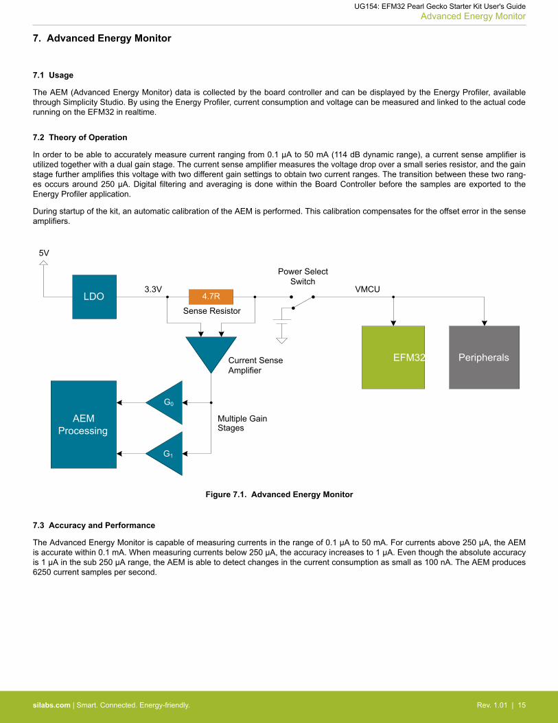
7.2 Theory of Operation
In order to be able to accurately measure current ranging from 0.1 µA to 50 mA (114 dB dynamic range), a current sense amplifier isutilized together with a dual gain stage. The current sense amplifier measures the voltage drop over a small series resistor, and the gainstage further amplifies this voltage with two different gain settings to obtain two current ranges. The transition between these two rang-es occurs around 250 µA. Digital filtering and averaging is done within the Board Controller before the samples are exported to theEnergy Profiler application.
During startup of the kit, an automatic calibration of the AEM is performed. This calibration compensates for the offset error in the senseamplifiers.
4.7R
Sense ResistorLDO
3.3V VMCU
Current Sense Amplifier
AEM Processing
Multiple GainStages
EFM32 Peripherals
Power Select Switch
5V
G0
G1
Figure 7.1. Advanced Energy Monitor
7.3 Accuracy and Performance
The Advanced Energy Monitor is capable of measuring currents in the range of 0.1 µA to 50 mA. For currents above 250 µA, the AEMis accurate within 0.1 mA. When measuring currents below 250 µA, the accuracy increases to 1 µA. Even though the absolute accuracyis 1 µA in the sub 250 µA range, the AEM is able to detect changes in the current consumption as small as 100 nA. The AEM produces6250 current samples per second.
UG154: EFM32 Pearl Gecko Starter Kit User's GuideAdvanced Energy Monitor
silabs.com | Smart. Connected. Energy-friendly. Rev. 1.01 | 15

8. On-Board Debugger
The SLSTK3401A contains an integrated debugger, which can be used to download code and debug the EFM32. In addition to pro-gramming the EFM32 on the kit, the debugger can also be used to program and debug external Silicon Labs EFM32, EFM8, EZR32and EFR32 devices.
The debugger supports three different debug interfaces used with Silicon Labs devices:• Serial Wire Debug, is used with all EFM32, EFR32 and EZR32 devices• JTAG, which can be used with some newer EFR32 and EFM32 devices• C2 Debug, which is used with EFM8 devices
In order for debugging to work properly, make sure you have the approriate debug interface selected that works with your device. Thedebug connector on the board supports all three of these modes.
UG154: EFM32 Pearl Gecko Starter Kit User's GuideOn-Board Debugger
silabs.com | Smart. Connected. Energy-friendly. Rev. 1.01 | 16
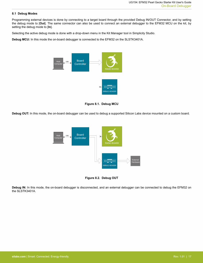
8.1 Debug Modes
Programming external devices is done by connecting to a target board through the provided Debug IN/OUT Connector, and by settingthe debug mode to [Out]. The same connector can also be used to connect an external debugger to the EFM32 MCU on the kit, bysetting the debug mode to [In].
Selecting the active debug mode is done with a drop-down menu in the Kit Manager tool in Simplicity Studio.
Debug MCU: In this mode the on-board debugger is connected to the EFM32 on the SLSTK3401A.
RADIO BOARD
BoardController
USBHostComputer
DEBUG HEADER
External Hardware
Figure 8.1. Debug MCU
Debug OUT: In this mode, the on-board debugger can be used to debug a supported Silicon Labs device mounted on a custom board.
BoardController
USBHostComputer
DEBUG HEADER
External Hardware
RADIO BOARD
Figure 8.2. Debug OUT
Debug IN: In this mode, the on-board debugger is disconnected, and an external debugger can be connected to debug the EFM32 onthe SLSTK3401A.
UG154: EFM32 Pearl Gecko Starter Kit User's GuideOn-Board Debugger
silabs.com | Smart. Connected. Energy-friendly. Rev. 1.01 | 17

BoardController
USBHostComputer
DEBUG HEADER
External Debug Probe
RADIO BOARD
Figure 8.3. Debug IN
Note: For "Debug IN" to work, the board controller on the kit must be powered throught the USB connector.
8.2 Debugging During Battery Operation
When the EFM32 is powered by battery and the J-Link USB is still connected, the on-board debug functionality is available. If the USBpower is disconnected, the Debug In mode will stop working.
If debug access is required when the target is running of another energy source, such as a battery, and the board controller is powereddown, the user should make direct connections to the GPIO used for debugging. This can be done by connecting to the appropriatepins of the breakout pads. Some Silicon Labs kits provide a dedicated pin header for this purpose.
UG154: EFM32 Pearl Gecko Starter Kit User's GuideOn-Board Debugger
silabs.com | Smart. Connected. Energy-friendly. Rev. 1.01 | 18

9. Board Support Package
The Board Support Package (BSP) is a set of C source and header files that enables easy access to, and control over some board-specific features. Using the BSP is not required, and the EFM32 is fully usable without the BSP.
The BSP uses EFM32 peripheral USART0, Location 0 (TX pin PA0, RX pin PA1) on baudrate 115200-8-N-1 to communicate with theboard controller.
Note:
The BSP functionality is only available when the Starter Kit is USB-powered. Using these function calls with USB disconnected will giveunpredictable results.
9.1 Application Programming Interface
To use the BSP, include the Starter Kit header file, like this:
#include "bsp.h"
All functions in the BSP are prefixed with BSP_. Some functions to control the user LEDs might look like:
int BSP_LedClear (int ledNo)
Turn off a single LED.
int BSP_LedSet (int ledNo)
Turn on a single LED.
9.2 Example Applications
Under the kits/SLSTK3401A/examples folder in your base Simplicity installation directory, you will find example programs using theBSP, with corresponding project/Makefiles for supported IDEs.
The examples folder also contains examples showing how to use the different peripherals on the SLSTK3401A.
9.3 How To Include In Your Own Applications
The easiest way to include the BSP in your application is to create it using the Simplicity IDE.
Alternatively, base your work on an example application that uses the BSP. The following items are recommended for correct configura-tion:
1. Make sure you define the correct part number (i.e., EFM32PG1B200F256GM48) as a preprocessor defined symbol2. Make sure you define the correct part number (i.e., EFM32PG1B200F256GM48) for your project file3. Add and include the EFM32 CMSIS-files (startup_efm32.s, system_efm32.c, core_cm3.c) to your project.4. Add and include all BSP package .c-files, with the bsp-prefix to your project5. Configure include paths to point at the CMSIS/CM3/CoreSupport and CMSIS/CM3/DeviceSupport/EnergyMicro/EFM32 directories6. Configure include paths to point to the kits/SLSTK3401A/bsp directory
Make sure you call "BSP_Init()" early at startup, and you should be all set.
UG154: EFM32 Pearl Gecko Starter Kit User's GuideBoard Support Package
silabs.com | Smart. Connected. Energy-friendly. Rev. 1.01 | 19
10. Integrated Development Environments
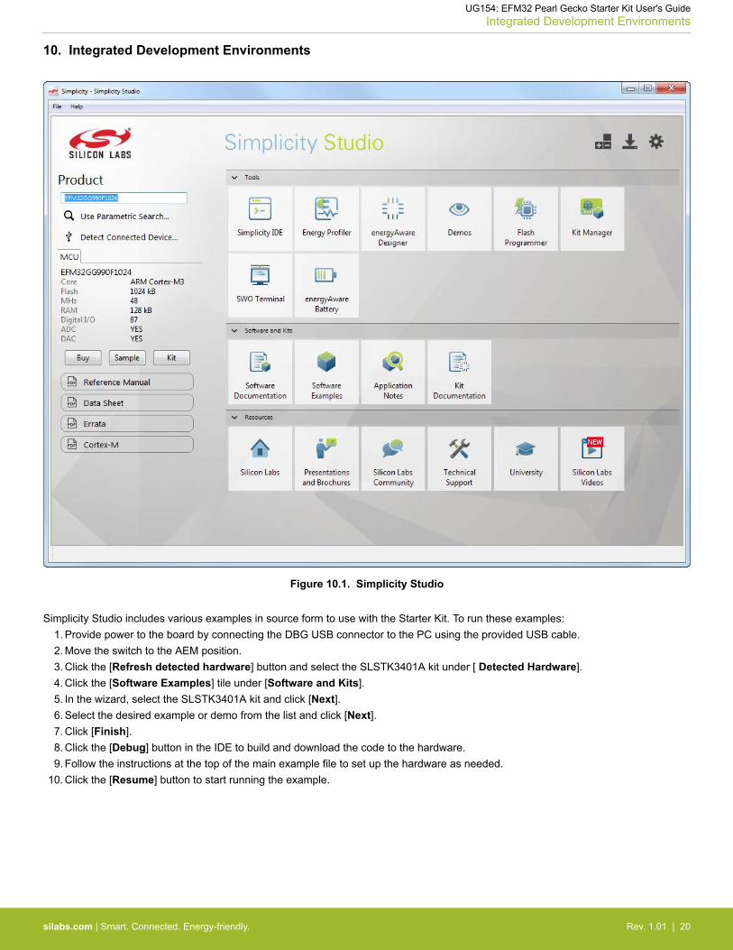
Figure 10.1. Simplicity Studio
Simplicity Studio includes various examples in source form to use with the Starter Kit. To run these examples:1. Provide power to the board by connecting the DBG USB connector to the PC using the provided USB cable.2. Move the switch to the AEM position.3. Click the [Refresh detected hardware] button and select the SLSTK3401A kit under [ Detected Hardware].4. Click the [Software Examples] tile under [Software and Kits].5. In the wizard, select the SLSTK3401A kit and click [Next].6. Select the desired example or demo from the list and click [Next].7. Click [Finish].8. Click the [Debug] button in the IDE to build and download the code to the hardware.9. Follow the instructions at the top of the main example file to set up the hardware as needed.
10. Click the [Resume] button to start running the example.
UG154: EFM32 Pearl Gecko Starter Kit User's GuideIntegrated Development Environments
silabs.com | Smart. Connected. Energy-friendly. Rev. 1.01 | 20

10.1 Third Party IDEs
The software examples in Simplicity Studio also include project files for several third party IDEs:• Atollic TrueSTUDIO® for ARM.• IAR Embedded Workbench® for ARM• Keil® MDK (µVision®)• Rowley CrossWorks™ for ARM• Makefile for GNU ARM Embedded Toolchain
These project files are located in separate subfolders in each example folder.
UG154: EFM32 Pearl Gecko Starter Kit User's GuideIntegrated Development Environments
silabs.com | Smart. Connected. Energy-friendly. Rev. 1.01 | 21
11. Kit Manager and Upgrades
The Kit Manager is a program that comes with Simplicity Studio. It can perform various kit- and EFM32-specific tasks.
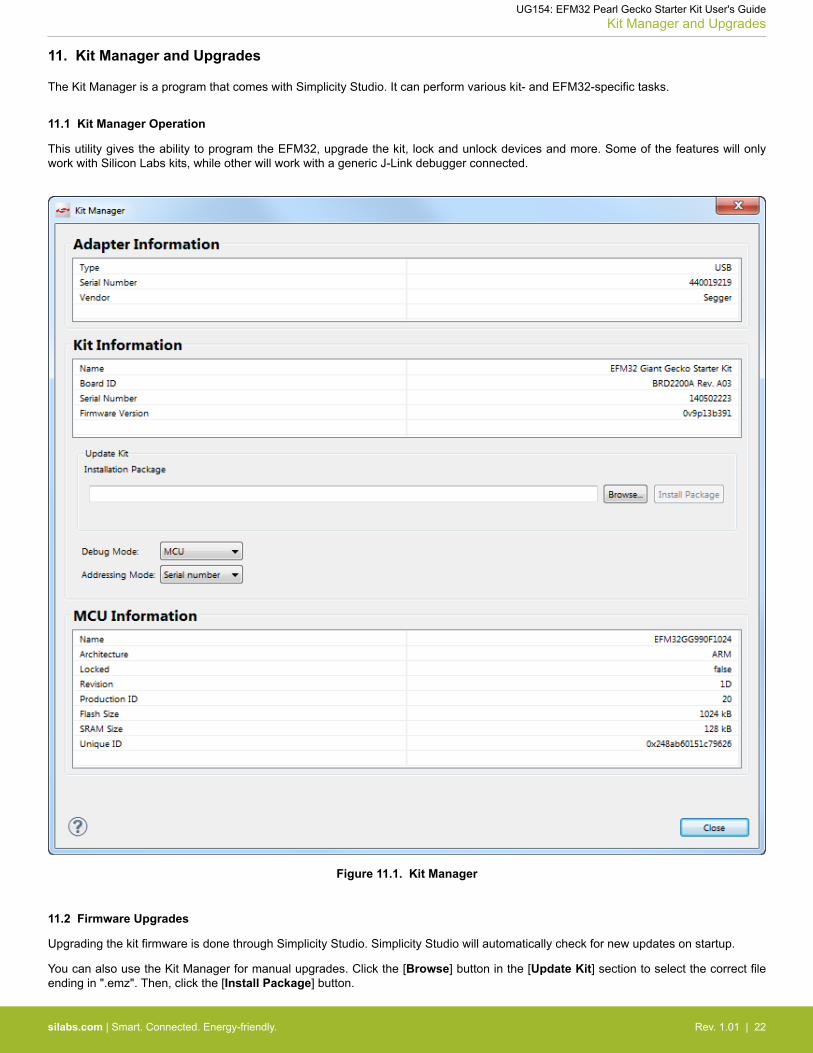
11.1 Kit Manager Operation
This utility gives the ability to program the EFM32, upgrade the kit, lock and unlock devices and more. Some of the features will onlywork with Silicon Labs kits, while other will work with a generic J-Link debugger connected.
Figure 11.1. Kit Manager
11.2 Firmware Upgrades
Upgrading the kit firmware is done through Simplicity Studio. Simplicity Studio will automatically check for new updates on startup.
You can also use the Kit Manager for manual upgrades. Click the [Browse] button in the [Update Kit] section to select the correct fileending in ".emz". Then, click the [Install Package] button.
UG154: EFM32 Pearl Gecko Starter Kit User's GuideKit Manager and Upgrades
silabs.com | Smart. Connected. Energy-friendly. Rev. 1.01 | 22

12. Schematics, Assembly Drawings and BOM
The schematics, assembly drawings and bill of materials (BOM) for the hardware included in the EFM32 Pearl Gecko Starter Kit areavailable through Simplicity Studio when the kit documentation package has been installed.
UG154: EFM32 Pearl Gecko Starter Kit User's GuideSchematics, Assembly Drawings and BOM
silabs.com | Smart. Connected. Energy-friendly. Rev. 1.01 | 23

13. Kit Revision History and Errata
13.1 Revision History
The kit revision can be found printed on the box label of the kit, as outlined in the figure below.
SLSTK3401AEFM32 Pearl Gecko Starter Kit
115100140
30-09-15
A00
Figure 13.1. Revision Info
Table 13.1. Kit Revision History
Kit Revision Released Description
B00 2016-09-28 Coin-cell battery no longer included with kit due to shipping restrictions.
A01 2016-07-04 Updated board revision to A01 - Updated EFM32 Pearl Gecko to revision C0.
A00 2015-09-30 Initial Kit Revision.
13.2 Errata
There are no known errata at present.
UG154: EFM32 Pearl Gecko Starter Kit User's GuideKit Revision History and Errata
silabs.com | Smart. Connected. Energy-friendly. Rev. 1.01 | 24

14. Document Revision History
1.01
2016-11-21
Corrected references to radio board.
1.00
2015-10-30
Initial document version.
UG154: EFM32 Pearl Gecko Starter Kit User's GuideDocument Revision History
silabs.com | Smart. Connected. Energy-friendly. Rev. 1.01 | 25

Table of Contents1. Introduction . . . . . . . . . . . . . . . . . . . . . . . . . . . . . . . . 1
1.1 Description . . . . . . . . . . . . . . . . . . . . . . . . . . . . . . . 1
1.2 Features. . . . . . . . . . . . . . . . . . . . . . . . . . . . . . . . 1
1.3 Getting Started . . . . . . . . . . . . . . . . . . . . . . . . . . . . . 1
2. Kit Block Diagram . . . . . . . . . . . . . . . . . . . . . . . . . . . . . 2
3. Kit Hardware Layout . . . . . . . . . . . . . . . . . . . . . . . . . . . . 3
4. Connectors . . . . . . . . . . . . . . . . . . . . . . . . . . . . . . . . 44.1 Breakout Pads . . . . . . . . . . . . . . . . . . . . . . . . . . . . . 4
4.2 Expansion Header . . . . . . . . . . . . . . . . . . . . . . . . . . . . 6
4.3 Debug Connector (DBG) . . . . . . . . . . . . . . . . . . . . . . . . . . 7
4.4 Simplicity Connector. . . . . . . . . . . . . . . . . . . . . . . . . . . . 8
5. Power Supply and Reset . . . . . . . . . . . . . . . . . . . . . . . . . . . 95.1 MCU Power Selection . . . . . . . . . . . . . . . . . . . . . . . . . . . 9
5.2 Board Controller Power. . . . . . . . . . . . . . . . . . . . . . . . . . . 9
5.3 EFM32 Reset . . . . . . . . . . . . . . . . . . . . . . . . . . . . . .10
6. Peripherals . . . . . . . . . . . . . . . . . . . . . . . . . . . . . . . .116.1 Push Buttons and LEDs . . . . . . . . . . . . . . . . . . . . . . . . . .11
6.2 Memory LCD-TFT Display. . . . . . . . . . . . . . . . . . . . . . . . . .12
6.3 Capacitive Touch Pads . . . . . . . . . . . . . . . . . . . . . . . . . . .13
6.4 Si7021 Relative Humidity and Temperature Sensor . . . . . . . . . . . . . . . . .13
6.5 USB to UART Bridge . . . . . . . . . . . . . . . . . . . . . . . . . . .14
7. Advanced Energy Monitor . . . . . . . . . . . . . . . . . . . . . . . . . 157.1 Usage . . . . . . . . . . . . . . . . . . . . . . . . . . . . . . . .15
7.2 Theory of Operation . . . . . . . . . . . . . . . . . . . . . . . . . . . .15
7.3 Accuracy and Performance . . . . . . . . . . . . . . . . . . . . . . . . .15
8. On-Board Debugger . . . . . . . . . . . . . . . . . . . . . . . . . . . . 168.1 Debug Modes . . . . . . . . . . . . . . . . . . . . . . . . . . . . . .17
8.2 Debugging During Battery Operation . . . . . . . . . . . . . . . . . . . . . .18
9. Board Support Package . . . . . . . . . . . . . . . . . . . . . . . . . . 199.1 Application Programming Interface . . . . . . . . . . . . . . . . . . . . . . .19
9.2 Example Applications . . . . . . . . . . . . . . . . . . . . . . . . . . .19
9.3 How To Include In Your Own Applications . . . . . . . . . . . . . . . . . . . .19
10. Integrated Development Environments . . . . . . . . . . . . . . . . . . . . 2010.1 Third Party IDEs . . . . . . . . . . . . . . . . . . . . . . . . . . . .21
Table of Contents 26

11. Kit Manager and Upgrades . . . . . . . . . . . . . . . . . . . . . . . . . 2211.1 Kit Manager Operation . . . . . . . . . . . . . . . . . . . . . . . . . .22
11.2 Firmware Upgrades . . . . . . . . . . . . . . . . . . . . . . . . . . .22
12. Schematics, Assembly Drawings and BOM . . . . . . . . . . . . . . . . . . 23
13. Kit Revision History and Errata . . . . . . . . . . . . . . . . . . . . . . . 2413.1 Revision History. . . . . . . . . . . . . . . . . . . . . . . . . . . . .24
13.2 Errata . . . . . . . . . . . . . . . . . . . . . . . . . . . . . . . .24
14. Document Revision History . . . . . . . . . . . . . . . . . . . . . . . . 25
Table of Contents . . . . . . . . . . . . . . . . . . . . . . . . . . . . . . 26
Table of Contents 27

http://www.silabs.com
Silicon Laboratories Inc.400 West Cesar ChavezAustin, TX 78701USA
Simplicity StudioOne-click access to MCU and wireless tools, documentation, software, source code libraries & more. Available for Windows, Mac and Linux!
IoT Portfoliowww.silabs.com/IoT
SW/HWwww.silabs.com/simplicity
Qualitywww.silabs.com/quality
Support and Communitycommunity.silabs.com
DisclaimerSilicon Labs intends to provide customers with the latest, accurate, and in-depth documentation of all peripherals and modules available for system and software implementers using or intending to use the Silicon Labs products. Characterization data, available modules and peripherals, memory sizes and memory addresses refer to each specific device, and "Typical" parameters provided can and do vary in different applications. Application examples described herein are for illustrative purposes only. Silicon Labs reserves the right to make changes without further notice and limitation to product information, specifications, and descriptions herein, and does not give warranties as to the accuracy or completeness of the included information. Silicon Labs shall have no liability for the consequences of use of the information supplied herein. This document does not imply or express copyright licenses granted hereunder to design or fabricate any integrated circuits. The products are not designed or authorized to be used within any Life Support System without the specific written consent of Silicon Labs. A "Life Support System" is any product or system intended to support or sustain life and/or health, which, if it fails, can be reasonably expected to result in significant personal injury or death. Silicon Labs products are not designed or authorized for military applications. Silicon Labs products shall under no circumstances be used in weapons of mass destruction including (but not limited to) nuclear, biological or chemical weapons, or missiles capable of delivering such weapons.
Trademark InformationSilicon Laboratories Inc.® , Silicon Laboratories®, Silicon Labs®, SiLabs® and the Silicon Labs logo®, Bluegiga®, Bluegiga Logo®, Clockbuilder®, CMEMS®, DSPLL®, EFM®, EFM32®, EFR, Ember®, Energy Micro, Energy Micro logo and combinations thereof, "the world’s most energy friendly microcontrollers", Ember®, EZLink®, EZRadio®, EZRadioPRO®, Gecko®, ISOmodem®, Precision32®, ProSLIC®, Simplicity Studio®, SiPHY®, Telegesis, the Telegesis Logo®, USBXpress® and others are trademarks or registered trademarks of Silicon Labs. ARM, CORTEX, Cortex-M3 and THUMB are trademarks or registered trademarks of ARM Holdings. Keil is a registered trademark of ARM Limited. All other products or brand names mentioned herein are trademarks of their respective holders.